WO2024142217A1 - 転がり軸受装置 - Google Patents
転がり軸受装置 Download PDFInfo
- Publication number
- WO2024142217A1 WO2024142217A1 PCT/JP2022/048140 JP2022048140W WO2024142217A1 WO 2024142217 A1 WO2024142217 A1 WO 2024142217A1 JP 2022048140 W JP2022048140 W JP 2022048140W WO 2024142217 A1 WO2024142217 A1 WO 2024142217A1
- Authority
- WO
- WIPO (PCT)
- Prior art keywords
- shaft portion
- inner ring
- shaft
- convex
- circumferential side
- Prior art date
- Legal status (The legal status is an assumption and is not a legal conclusion. Google has not performed a legal analysis and makes no representation as to the accuracy of the status listed.)
- Ceased
Links
Images


Classifications
-
- F—MECHANICAL ENGINEERING; LIGHTING; HEATING; WEAPONS; BLASTING
- F16—ENGINEERING ELEMENTS AND UNITS; GENERAL MEASURES FOR PRODUCING AND MAINTAINING EFFECTIVE FUNCTIONING OF MACHINES OR INSTALLATIONS; THERMAL INSULATION IN GENERAL
- F16C—SHAFTS; FLEXIBLE SHAFTS; ELEMENTS OR CRANKSHAFT MECHANISMS; ROTARY BODIES OTHER THAN GEARING ELEMENTS; BEARINGS
- F16C19/00—Bearings with rolling contact, for exclusively rotary movement
- F16C19/02—Bearings with rolling contact, for exclusively rotary movement with bearing balls essentially of the same size in one or more circular rows
- F16C19/14—Bearings with rolling contact, for exclusively rotary movement with bearing balls essentially of the same size in one or more circular rows for both radial and axial load
- F16C19/18—Bearings with rolling contact, for exclusively rotary movement with bearing balls essentially of the same size in one or more circular rows for both radial and axial load with two or more rows of balls
-
- F—MECHANICAL ENGINEERING; LIGHTING; HEATING; WEAPONS; BLASTING
- F16—ENGINEERING ELEMENTS AND UNITS; GENERAL MEASURES FOR PRODUCING AND MAINTAINING EFFECTIVE FUNCTIONING OF MACHINES OR INSTALLATIONS; THERMAL INSULATION IN GENERAL
- F16C—SHAFTS; FLEXIBLE SHAFTS; ELEMENTS OR CRANKSHAFT MECHANISMS; ROTARY BODIES OTHER THAN GEARING ELEMENTS; BEARINGS
- F16C33/00—Parts of bearings; Special methods for making bearings or parts thereof
- F16C33/30—Parts of ball or roller bearings
- F16C33/58—Raceways; Race rings
Definitions
- the present invention relates to a rolling bearing device.
- a rolling bearing device for supporting the driving wheels of an automobile has an outer ring 91 fixed to the vehicle body, an inner member 92 to which a wheel 90 is attached, and two rows of rolling elements 93 arranged between the outer ring 91 and the inner member 92.
- the inner member 92 is connected to a rotating shaft 99 of a constant velocity joint. The torque of the rotating shaft 99 is transmitted to the inner member 92.
- the inner member 92 has an inner shaft 94, and a first inner ring 95a and a second inner ring 95b attached to the inner shaft 94.
- the rotating shaft 99 has a small diameter shaft portion 98 that passes through the inner shaft 94, a large diameter shaft portion 97, and a step portion 96 located between the small diameter shaft portion 98 and the large diameter shaft portion 97.
- the small diameter shaft portion 98 has a male thread portion 98a on the vehicle outer side.
- a nut 101 is attached to the male thread portion 98a. When the nut 101 is tightened, a large axial force is applied to the small diameter shaft portion 98. As a result, the step portion 96 and the first inner ring 95a are pressed against each other in the axial direction.
- Patent Document 1 discloses that the abnormal noise is caused by stick-slip (microscopic slippage) between the step 96 and the first inner ring 95a, and discloses a lubrication ring member 100 for suppressing the abnormal noise.
- the rolling bearing device disclosed in Patent Document 1 has a lubrication ring member 100 interposed between the step portion 96 and the first inner ring 95.
- the lubrication ring 100 intentionally facilitates sliding between the step portion 96 and the first inner ring 95. This is thought to allow the energy caused by the torsion to be released early, suppressing the generation of abnormal noise.
- it is very difficult to set the degree of slippage caused by the lubrication ring member 100, and there are cases in which the effect of the lubrication ring member 100 in suppressing abnormal noise is low.
- the present disclosure therefore aims to provide a rolling bearing device that has new technical means for suppressing abnormal noise caused by stick-slip.
- the rolling bearing for a wheel is an outer ring, a first inner ring, a first rolling element arranged to be able to roll between the outer ring and the first inner ring, and a rotating shaft having a step portion located adjacent to the first inner ring in the axial direction,
- a rolling bearing device in which the first inner ring and the step portion are pressed against each other in an axial direction, The step portion has a flat contact surface facing a first axial direction side, the first inner ring has a back surface facing a second axial side and in contact with the contact surface,
- the back surface is the first inner ring has arc-shaped convex surface regions and arc-shaped flat surface regions alternately in a circumferential direction, the convex surface regions and the flat surface regions being centered on a point on the central axis of the first inner ring,
- the convex surface region has a flat surface and a plurality of convex portions protruding from the flat surface in the axial direction, The flat area does not
- the rolling bearing device can suppress abnormal noise caused by stick-slip.
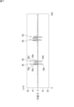
- FIG. 1 is a cross-sectional view showing a rolling bearing device according to a first embodiment of the present invention.
- FIG. 2 is an enlarged cross-sectional view showing a portion of the rolling bearing device shown in FIG.
- FIG. 3 is a sectional view showing a second embodiment of the rolling bearing device of the present invention.
- FIG. 4 is an enlarged cross-sectional view showing a part of the rolling bearing device shown in FIG.
- FIG. 5 is an explanatory diagram showing an example of the back surface of the first inner ring.
- FIG. 6 is an explanatory diagram showing the letter "O" which becomes a convex portion.
- FIG. 7 is an explanatory diagram showing a cross section of a part of a character or the like.
- FIG. 8 is a cross-sectional view showing a conventional rolling bearing device.
- a rolling bearing device is an outer ring, a first inner ring, a first rolling element arranged to be able to roll between the outer ring and the first inner ring, and a rotating shaft having a step portion located adjacent to the first inner ring in the axial direction,
- the step portion has a flat contact surface facing a first axial direction side
- the first inner ring has a back surface facing a second axial side and in contact with the contact surface
- the back surface is the first inner ring has arc-shaped convex surface regions and arc-shaped flat surface regions alternately in a circumferential direction, the convex surface regions and the flat surface regions being centered on a point on the central axis of the first inner ring
- the convex surface region has a flat surface and a plurality of
- the flat area of the first inner ring comes into surface contact with the contact surface of the rotating shaft. This positions the first inner ring and the rotating shaft, improving the assembly precision between the first inner ring and the rotating shaft.
- the convex portion of the convex area of the first inner ring can bite into the contact surface of the rotating shaft. This restricts the relative rotation between the first inner ring and the rotating shaft, making it possible to suppress abnormal noise caused by stick-slip.
- the rolling bearing device of (1) further comprises: A second inner ring; A second rolling element that is rollably disposed between the outer ring and the second inner ring;
- An inner shaft The inner shaft is a first shaft portion having a small diameter on which the first inner ring and the second inner ring are fitted; A second shaft portion located on a first axial side of the first shaft portion and having an outer diameter larger than that of the first shaft portion; a first step portion located between the first shaft portion and the second shaft portion; an axial through hole provided in the first shaft portion and the second shaft portion;
- the rotation shaft is a third shaft portion having a small diameter and located within the through hole; a fourth shaft portion located on a second axial side of the third shaft portion and having an outer diameter larger than that of the third shaft portion; a second step portion as the step portion located between the third shaft portion and the fourth shaft portion,
- the back surface of the second inner ring contacts the first step portion, a front surface of the second inner ring contacts a front surface of the first inner ring;
- the rolling bearing device further comprises: The inner axis and a second rolling element disposed between the outer ring and a portion of the inner shaft so as to be capable of rolling;
- the inner shaft is a first shaft portion having a small diameter on which the first inner ring is fitted;
- a second shaft portion located on a first axial side of the first shaft portion and having an outer diameter larger than that of the first shaft portion;
- a first step portion located between the first shaft portion and the second shaft portion; an axial through hole provided in the first shaft portion and the second shaft portion;
- the second shaft portion has an inner ring raceway with which the second rolling element rolls
- the rotation shaft is a third shaft portion having a small diameter and located within the through hole; a fourth shaft portion located on a second axial side of the third shaft portion and having an outer diameter larger than that of the third shaft portion; a second step portion as the step portion located between the third shaft portion and the fourth shaft portion,
- a front surface of the first inner ring contacts the first step portion,
- the height of the protrusion in a direction perpendicular to the plane is not less than 5 ⁇ m and not more than 30 ⁇ m. This configuration enhances the effect of the protrusion biting into the contact surface.
- the protrusion is not too high, and the flat area of the first inner ring can come into surface contact with the contact surface of the rotating shaft.
- the hub unit 11 is coaxial with the rotating shaft 51 of the joint 50. In other words, the hub unit 11 and the rotating shaft 51 share a common central axis C.
- the direction along this central axis C is defined as the "axial direction”.
- This axial direction also includes a direction parallel to the central axis C.
- the first axial side (left side in FIG. 1) is the vehicle outer side, and the opposite second axial side (right side in FIG. 1) is the vehicle inner side.
- the direction perpendicular to the central axis C is defined as the "radial direction”.
- the direction along a circle centered on the central axis C is defined as the "circumferential direction”.
- the hub unit 11 is attached to a suspension system of the vehicle body and rotatably supports a wheel and a disc rotor (not shown) of a brake system.
- the hub unit 11 has a cylindrical outer ring 15, an inner member 12 having a portion located radially inward of the outer ring 15, a plurality of balls (rolling elements) 13 arranged in two rows between the outer ring 15 and the inner member 12, and two annular retainers 14 which each hold the two rows of balls 13.
- FIG. 2 is an enlarged cross-sectional view showing a portion of the rolling bearing device 10 shown in FIG.
- the outer ring 15 has a fixing flange 16 on its outer periphery, which is fixed to a part of the suspension device.
- the outer ring 15 has a first outer ring raceway 17a and a second outer ring raceway 17b on its inner periphery.
- the inner member 12 has an inner shaft 20 and a first inner ring 21 attached to the vehicle inner side of the inner shaft 20.
- the inner shaft 20 has a first shaft portion 23, a second shaft portion 24 having an outer diameter larger than that of the first shaft portion 23, and a first step portion 33 located between the small diameter first shaft portion 23 and the large diameter second shaft portion 24.
- the large diameter second shaft portion 24 is located on the vehicle outer side of the small diameter first shaft portion 23.
- the large diameter second shaft portion 24 has a flange 25 for mounting a wheel or the like.
- the large diameter second shaft portion 24 has a second inner ring raceway 26b with which the balls 13 roll and come into contact.
- the first inner ring 21 has a first inner ring raceway 26a with which the balls 13 roll and make contact.
- the first inner ring 21 has a back surface 31 facing the vehicle inner side.
- the back surface 31 is the side surface of the first inner ring 21 on the vehicle inner side.
- the first inner ring 21 has a front surface 32 facing the vehicle outer side.
- the front surface 32 is the side surface of the first inner ring 21 on the vehicle outer side.
- the first inner ring 21 fits around a small-diameter first shaft portion 23.
- the first inner ring 21 is attached to the first shaft portion 23 with a tightening margin.
- the front surface 32 of the first inner ring 21 comes into contact with a first step portion 33.
- the rotating shaft 51 of the joint 50 is a shaft that transmits torque to the inner member 12 of the hub unit 11.
- the rotating shaft 51 has a small-diameter third shaft portion 53, a fourth shaft portion (cup portion) 52 having an outer diameter larger than that of the third shaft portion 53, and a second step portion 58 located between the small-diameter third shaft portion 53 and the large-diameter fourth shaft portion 52.
- the second step portion 58 and the fourth shaft portion 52 are located on the vehicle inner side of the third shaft portion 53.
- the fourth shaft portion 52 has a bottomed cylindrical shape that opens toward the vehicle inner side.
- the small-diameter third shaft portion 53 is located within the through hole 27 of the inner shaft 20.
- the second step portion 58 has an annular, flat contact surface 54 facing the vehicle outer side.
- the small-diameter third shaft portion 53 has a splined shaft portion 55 that is splined and fitted into the splined hole portion 28 of the inner shaft 20, and a non-splined shaft portion 56 that is not splined and fitted into the inner shaft 20.
- the non-splined shaft portion 56 and the non-splined hole portion 29 face each other in the radial direction.
- the small-diameter third shaft portion 53 has a male thread portion 57 on the vehicle outer side.
- the rolling bearing device 10 has a fastening member 60 for connecting the joint 50 and the inner member 12.
- the fastening member 60 is a nut and has a female thread portion 60a.
- the fastening member 60 is in close contact with the vehicle outer side surface of the inner shaft 20 by tightening the female thread portion 60a to the male thread portion 57.
- a large axial force axial force
- the second step portion 58 of the joint 50 and the first inner ring 21 are in a state of being pressed against each other in the axial direction.
- the first step portion 33 of the inner shaft 20 and the first inner ring 21 are in a state of being pressed against each other in the axial direction.
- the rolling bearing device 10 shown in FIG. 1 has the hub unit 11 and the rotating shaft 51 of the joint 50 .
- the hub unit 11 has an outer ring 15, an inner shaft 20, a first inner ring 21, balls 13 as first rolling bodies arranged to be rollable between the outer ring 15 and the first inner ring 21, and balls 13 as second rolling bodies arranged to be rollable between the outer ring 15 and a portion of the inner shaft 20.
- Fig. 3 is a cross-sectional view showing a second embodiment of the rolling bearing device of the present invention.
- the rolling bearing device 10 shown in Fig. 3 is a bearing device for supporting the driving wheels of an automobile.
- the rolling bearing device 10 has a hub unit 11 and a constant velocity universal joint 50 (hereinafter referred to as "joint 50") connected to the hub unit 11.
- Fig. 3 shows a rotating shaft 51 which is a part of the joint 50.
- the inner member 12 has an inner shaft 20, a first inner ring 21, and a second inner ring 22.
- the first inner ring 21 is attached to the vehicle inner side of the inner shaft 20.
- the second inner ring 22 is located on the vehicle outer side of the first inner ring 21.
- the inner shaft 20 has a first shaft portion 23, a second shaft portion 24 having an outer diameter larger than that of the first shaft portion 23, and a first step portion 33 located between the small diameter first shaft portion 23 and the large diameter second shaft portion 24.
- the large diameter second shaft portion 24 is located on the vehicle outer side of the small diameter first shaft portion 23.
- the large diameter second shaft portion 24 has a flange 25 to which a wheel or the like is attached.
- the first inner ring 21 has a first inner ring raceway 26a with which the balls 13 roll.
- the first inner ring 21 has a back surface 31 facing the vehicle inner side.
- the back surface 31 is the side surface of the first inner ring 21 on the vehicle inner side.
- the first inner ring 21 has a front surface 32 facing the vehicle outer side.
- the front surface 32 is the side surface of the first inner ring 21 on the vehicle outer side.
- the first inner ring 21 fits onto the small-diameter first shaft portion 23.
- the first inner ring 21 is attached to the first shaft portion 23 with a tightening margin.
- the back surface 31 of the first inner ring 21 contacts the second step portion 58 of the rotating shaft 51 of the joint 50.
- the second inner ring 22 has a second inner ring raceway 26b with which the balls 13 roll.
- the second inner ring 22 has a front surface 37 facing the vehicle inner side.
- the front surface 37 is the side surface of the second inner ring 22 facing the vehicle inner side.
- the second inner ring 22 has a back surface 36 facing the vehicle outer side.
- the back surface 36 is the side surface of the second inner ring 22 facing the vehicle outer side.
- the second inner ring 22 fits onto the small diameter first shaft portion 23.
- the second inner ring 22 is attached to the first shaft portion 23 with a tightening margin.
- the front surface 37 of the second inner ring 22 contacts the front surface 32 of the first inner ring 21.
- the back surface 36 of the second inner ring 22 contacts the first step portion 33.
- the small-diameter third shaft portion 53 has a splined shaft portion 55 that is splined and fitted into the splined hole portion 28 of the inner shaft 20, and a non-splined shaft portion 56 that is not splined and fitted into the inner shaft 20.
- the non-splined shaft portion 56 and the non-splined hole portion 29 face each other in the radial direction.
- the small-diameter third shaft portion 53 has a male thread portion 57 on the vehicle outer side.
- the rolling bearing device 10 has a fastening member 60 for connecting the joint 50 and the inner member 12.
- the fastening member 60 is a nut and has a female thread portion 60a.
- the fastening member 60 is in close contact with the vehicle outer side surface of the inner shaft 20 by tightening the female thread portion 60a to the male thread portion 57.
- a large axial force axial force
- the second step portion 58 of the joint 50 and the first inner ring 21 are in a state of being pressed against each other in the axial direction.
- the first step portion 33 of the inner shaft 20 and the second inner ring 22 are in a state of being pressed against each other in the axial direction.
- the first inner ring 21 and the second inner ring 22 are in a state of being pressed against each other in the axial direction.
- the contact surface 54 of the second step 58 of the joint 50 is positioned axially opposite the back surface 31 of the first inner ring 21. As described above, the second step 58 and the first inner ring 21 press against each other in the axial direction. Therefore, the contact surface 54 of the second step 58 and the back surface 31 of the first inner ring 21 press against each other.
- the back surface 31 has a number of protrusions 73.
- the multiple protrusions 73 are positioned along the circumferential direction of the annular back surface 31.
- Each of the protrusions 73 is made up of a letter, a number, a symbol, or a pattern.
- the back surface 31 has, as protrusions 73, the letters “A” to “Z”, the numbers “1", “2", and “3", and the symbol " ⁇ ”. Additionally, the back surface 31 may have a pattern such as a wavy line as the protrusions 73.
- letters, numbers, symbols, or patterns are referred to as "letters, etc.”.
- FIG. 6 is an explanatory diagram showing the alphabet "O" which becomes the convex portion 73.
- the laser processed portion of the back surface 31 becomes a groove 89.
- the letters and the like are written by the groove 89.
- the letters and the like are written by a double line having two grooves 89 recessed from the flat surface 72 of the back surface 31.
- the alphabet "O” is written by an inner groove 89 and an outer groove 89. Numbers, symbols, and patterns other than letters are also written by a double line having two grooves 89 recessed from the flat surface 72.
- Each groove 89 is carved by laser processing.
- each of both edges 89a of one groove 89 a portion protruding from the flat surface 72 is generated as a burr, and each of both edges 89a has a shape protruding from the flat surface 72 and having a pointed tip.
- the convex portion 73 is formed by a collection of such portions (pointed portions) having a pointed tip.
- the back surface 31 has letters, numbers, symbols or patterns as the protrusions 73.
- the letters, numbers, symbols or patterns are written by a double line having two grooves 89 recessed from the flat surface 72.
- the edges 89a of each of the grooves 89 of the double line protrude from the flat surface 72 and have a pointed tip.
- each convex surface region 71 will be described from the convex portion 73 located closest to the first circumferential side to the convex portion 73 located closest to the second circumferential side.
- the range from the letter "U”, which is one convex portion 73 included in one convex surface region 71 located on the left side of Figure 5, to the symbol " ⁇ " will be described.
Landscapes
- Engineering & Computer Science (AREA)
- General Engineering & Computer Science (AREA)
- Mechanical Engineering (AREA)
- Rolling Contact Bearings (AREA)
Priority Applications (2)
| Application Number | Priority Date | Filing Date | Title |
|---|---|---|---|
| JP2024567000A JPWO2024142217A1 (https=) | 2022-12-27 | 2022-12-27 | |
| PCT/JP2022/048140 WO2024142217A1 (ja) | 2022-12-27 | 2022-12-27 | 転がり軸受装置 |
Applications Claiming Priority (1)
| Application Number | Priority Date | Filing Date | Title |
|---|---|---|---|
| PCT/JP2022/048140 WO2024142217A1 (ja) | 2022-12-27 | 2022-12-27 | 転がり軸受装置 |
Publications (1)
| Publication Number | Publication Date |
|---|---|
| WO2024142217A1 true WO2024142217A1 (ja) | 2024-07-04 |
Family
ID=91716659
Family Applications (1)
| Application Number | Title | Priority Date | Filing Date |
|---|---|---|---|
| PCT/JP2022/048140 Ceased WO2024142217A1 (ja) | 2022-12-27 | 2022-12-27 | 転がり軸受装置 |
Country Status (2)
| Country | Link |
|---|---|
| JP (1) | JPWO2024142217A1 (https=) |
| WO (1) | WO2024142217A1 (https=) |
Citations (2)
| Publication number | Priority date | Publication date | Assignee | Title |
|---|---|---|---|---|
| JP2011196456A (ja) * | 2010-03-19 | 2011-10-06 | Ntn Corp | 車輪用軸受装置 |
| JP2011240857A (ja) * | 2010-05-20 | 2011-12-01 | Ntn Corp | 車輪用軸受装置 |
-
2022
- 2022-12-27 WO PCT/JP2022/048140 patent/WO2024142217A1/ja not_active Ceased
- 2022-12-27 JP JP2024567000A patent/JPWO2024142217A1/ja active Pending
Patent Citations (2)
| Publication number | Priority date | Publication date | Assignee | Title |
|---|---|---|---|---|
| JP2011196456A (ja) * | 2010-03-19 | 2011-10-06 | Ntn Corp | 車輪用軸受装置 |
| JP2011240857A (ja) * | 2010-05-20 | 2011-12-01 | Ntn Corp | 車輪用軸受装置 |
Also Published As
| Publication number | Publication date |
|---|---|
| JPWO2024142217A1 (https=) | 2024-07-04 |
Similar Documents
| Publication | Publication Date | Title |
|---|---|---|
| EP1311771B1 (en) | Wheel drive unit | |
| WO2008059615A1 (en) | Bearing device for vehicle | |
| WO2010147135A1 (ja) | 車輪用軸受 | |
| US8684878B2 (en) | Speed reducer | |
| JP4489672B2 (ja) | 車輪用軸受装置 | |
| EP3546777B1 (en) | Hub unit bearing, method for manufacturing same, motor vehicle, and method for manufacturing same | |
| WO2007091408A1 (ja) | 車輪用軸受装置 | |
| JP6366233B2 (ja) | 車輪用軸受装置 | |
| JP2005042894A (ja) | 複列転がり軸受装置 | |
| WO2024142217A1 (ja) | 転がり軸受装置 | |
| JP2004019731A (ja) | 自動調心ころ軸受 | |
| JP2005212713A (ja) | 車輪用軸受装置 | |
| KR20200031901A (ko) | 허브 조립체 및 휠 베어링 조립체 | |
| US20220341467A1 (en) | Bearing with integrated axial preload and method thereof | |
| US20090046973A1 (en) | Bearing retention method and apparatus | |
| JP2021167647A (ja) | 転がり軸受 | |
| JPS5855362B2 (ja) | 二方向荷重型玉軸受 | |
| US12590607B2 (en) | Bearing | |
| KR102925608B1 (ko) | 센터볼트 체결 구조를 가지는 자동차용 휠 허브 베어링 유닛 | |
| JP2025072052A (ja) | 車輪用軸受装置 | |
| CN119435578A (zh) | 车轮用轴承装置 | |
| JP2025072047A (ja) | 車輪用軸受装置 | |
| JP2025033576A (ja) | 車輪用軸受装置 | |
| JP2004308716A (ja) | 軸受ユニット | |
| JP2022154868A (ja) | ハブユニット軸受 |
Legal Events
| Date | Code | Title | Description |
|---|---|---|---|
| 121 | Ep: the epo has been informed by wipo that ep was designated in this application |
Ref document number: 22970011 Country of ref document: EP Kind code of ref document: A1 |
|
| WWE | Wipo information: entry into national phase |
Ref document number: 2024567000 Country of ref document: JP |
|
| NENP | Non-entry into the national phase |
Ref country code: DE |
|
| 122 | Ep: pct application non-entry in european phase |
Ref document number: 22970011 Country of ref document: EP Kind code of ref document: A1 |