WO2024142155A1 - エレベータ装置 - Google Patents
エレベータ装置 Download PDFInfo
- Publication number
- WO2024142155A1 WO2024142155A1 PCT/JP2022/047906 JP2022047906W WO2024142155A1 WO 2024142155 A1 WO2024142155 A1 WO 2024142155A1 JP 2022047906 W JP2022047906 W JP 2022047906W WO 2024142155 A1 WO2024142155 A1 WO 2024142155A1
- Authority
- WO
- WIPO (PCT)
- Prior art keywords
- control device
- car
- elevator
- power
- state
- Prior art date
- Legal status (The legal status is an assumption and is not a legal conclusion. Google has not performed a legal analysis and makes no representation as to the accuracy of the status listed.)
- Ceased
Links
Images



Classifications
-
- B—PERFORMING OPERATIONS; TRANSPORTING
- B66—HOISTING; LIFTING; HAULING
- B66B—ELEVATORS; ESCALATORS OR MOVING WALKWAYS
- B66B5/00—Applications of checking, fault-correcting, or safety devices in elevators
- B66B5/02—Applications of checking, fault-correcting, or safety devices in elevators responsive to abnormal operating conditions
-
- B—PERFORMING OPERATIONS; TRANSPORTING
- B66—HOISTING; LIFTING; HAULING
- B66B—ELEVATORS; ESCALATORS OR MOVING WALKWAYS
- B66B5/00—Applications of checking, fault-correcting, or safety devices in elevators
- B66B5/02—Applications of checking, fault-correcting, or safety devices in elevators responsive to abnormal operating conditions
- B66B5/16—Braking or catch devices operating between cars, cages, or skips and fixed guide elements or surfaces in hoistway or well
- B66B5/18—Braking or catch devices operating between cars, cages, or skips and fixed guide elements or surfaces in hoistway or well and applying frictional retarding forces
- B66B5/22—Braking or catch devices operating between cars, cages, or skips and fixed guide elements or surfaces in hoistway or well and applying frictional retarding forces by means of linearly-movable wedges
Definitions
- Elevator systems are equipped with a governor and an emergency stop device to constantly monitor the ascending and descending speed of the car and bring the car to an emergency stop if it becomes overspeeding to a certain extent.
- the car and the governor are connected by a governor rope, and when an overspeeding state is detected, the governor restrains the governor rope, activating the emergency stop device on the car side and bringing the car to an emergency stop.
- the elevator system of the present invention comprises a car, an emergency stop device provided in the car, and an electric actuator that activates the emergency stop device, and also comprises a first control device that detects and stores the running state of the car during a power outage, and a second control device that returns the electric actuator that was activated in response to the power outage to a standby state based on the running state stored by the first control device.
- elevator equipment equipped with an electric emergency stop device can be smoothly restored when power is restored.
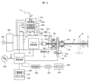
- FIG. 1 is a schematic configuration diagram of an elevator system according to an embodiment of the present invention
- FIG. 2 is a plan view showing a mechanism of the electric actuator according to the embodiment.
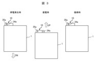
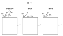
- 1 is an operational state diagram showing an example of the operation of an elevator car of an embodiment during a power outage and upon power restoration.
- 4 is a flowchart showing a processing operation of the safety control device in the embodiment at the time of a power outage. 4 is a flowchart showing a processing operation for returning an electric operating device to a normal state in the elevator control device according to the embodiment.
- an image sensor may be used as the speed sensor.
- the position and speed of the car 1 are detected based on image information of the surface condition of the guide rail 4 acquired by the image sensor. For example, the speed is calculated from the moving distance of the image feature in a given time.
- the drive shaft 12 is driven by the biasing force of the drive spring 13 (Fig. 1) in the direction from the fixed part 14 (Fig. 1) to the pressing member (Fig. 1) received by the pressing member 15 (Fig. 1) of the drive shaft 12.
- the first link member (operating lever 11 and first operating piece 16: Fig. 1) connected to the drive shaft 12 rotates around the first operating shaft 19 (Fig. 1).
- the second link member (connecting piece 17 and second operating piece 18: Fig. 1) connected to the drive shaft 12 rotates around the second operating shaft 20 (Fig. 1). This causes the lifting rod 21 (Fig. 1) connected to the second operating piece 18 to be pulled up.
- the motor control device 112 has a drive circuit for the motor 37 and controls the rotation of the motor 37 in response to a control command from the elevator control device 7.
- the motor 37 may be either a DC motor or an AC motor.
- the monitoring device 600 monitors the operating status of the elevator equipment based on information held by the elevator control device 7. When an abnormality occurs in the elevator equipment, the monitoring device 600 transmits an abnormality alert signal and information on the operating status indicating the abnormality via the communication network 700 to a monitoring server 801 installed in a control center 800 located geographically away from the installation location of the elevator equipment.
- the electric actuator 10 When the emergency stop device 2 is deactivated, the electric actuator 10 returns to the standby state by driving the electromagnet 35a to return the movable element to the standby position.
- the elevator control device 7 is equipped with a computer system such as a microcomputer, independent of the safety control device 103. This computer system executes a specific program, causing the elevator control device 7 to execute the recovery process for the electric actuator 10.
- step S402 the elevator control device 7 determines whether data related to the running state of the car 1 during a power outage, i.e., data on the running direction, speed, and position, is stored in the non-volatile memory device 130 in the safety control device 103. Therefore, in step S402, the elevator control device 7 determines whether the safety control device 103 has executed the power outage processing described above (FIG. 5).
- step S405 the elevator control device 7 uses the monitoring device 600 to report an abnormality to the monitoring server 801 installed in the control center 800, and puts the elevator device into a pause state.
- step S403 If the elevator control device 7 determines that the travel direction, speed, and position data are stored (YES in step S402), it then executes step S403.
- step S406 determines that the traveling direction is not a downward direction, that is, that the traveling direction is an upward direction or the car 1 is stopped and the return operation of the electric operator 10 is possible (NO in step S403), it then executes step S406.
- step S404 determines that the speed of the car 1 is equal to or greater than the threshold value (YES in step S404), i.e., that it is difficult to restore the electric actuator 10, it next executes step S405.
- the elevator control device 7 uses the monitoring device 600 to report an abnormality to the monitoring server 801 installed in the control center 800, and puts the elevator device into a paused state.
- step S404 determines that the speed of the car 1 is not equal to or greater than the threshold (NO in step S404), that is, that the return operation of the electric actuator 10 is possible, it then executes step S406.
- step S406 the elevator control device 7 determines whether the current position of the car 1 is lower than the position of the car 1 before it stopped at the time of the power outage, which is stored in the non-volatile memory device 130, based on data regarding the running state of the car 1 obtained from the non-volatile memory device 130 provided in the safety control device 103.
- the elevator control device 7 regards the stopping position of the car 1 at the time of the power outage, which is stored in the non-volatile memory device 130, as the current position of the car 1. Furthermore, if there are multiple pieces of position data before the car 1 stops at the time of the power outage, the position before the car 1 stops at the time of the power outage is the position indicated by any one of the multiple pieces of data. Therefore, in step S406, the elevator control device 7 determines whether the car descended during the power outage.
- step S407 the elevator control device 7 operates the car 1 in the upward (UP) direction. At this time, the elevator control device 7 controls the upward operation of the car 1 based on the position of the car 1 stored in the non-volatile memory device 130.
- step S408 the elevator control device 7 uses the motor control device 112 to rotate the return motor (motor 37 in FIG. 2) forward and reverse, as described above, to return the electric operator 10 to the standby state.
- the safety control device 103 which controls the electric operator 10 to activate the emergency stop device 2, detects and stores the running state of the car 1 during a power outage, and when power is restored, the elevator control device 7 returns the electric operator 10 to a standby state according to the running state of the car 1 stored by the safety control device 103.
- the elevator control device 7 returns the electric operator 10 to a standby state according to the running state of the car 1 stored by the safety control device 103.
- the safety control device 103 detects and stores the running state of the car 1 during a power outage, but a control device for detecting the running state during a power outage may be provided independent of the safety control device 103. Since the safety control device 103 has a function for emergency stopping the car 1 according to the running state of the car 1, even if it further has a function for executing the power outage processing as shown in FIG. 5, the number of parts such as microcomputers does not increase.
- the elevator system may have a machine room, or it may be a so-called machine room-less elevator that does not have a machine room.
Landscapes
- Engineering & Computer Science (AREA)
- Mechanical Engineering (AREA)
- Maintenance And Inspection Apparatuses For Elevators (AREA)
- Elevator Control (AREA)
Abstract
Description
エレベータ制御装置7は、走行方向が下降方向であり、電動操作器10の復帰動作が難しくなり得ると判定すると(ステップS403のYES)、次に、ステップS404を実行する。また、エレベータ制御装置7は、走行方向が下降方向ではない、すなわち上昇方向もしくは乗りかご1が停止であり、電動操作器10の復帰動作が可能であると判定すると(ステップS403のNO)、次に、ステップS406を実行する。
Claims (10)
- 乗りかごと、
前記乗りかごに設けられる非常止め装置と、
前記非常止め装置を作動させる電動操作器と、
を備えるエレベータ装置において、
停電の間に、前記乗りかごの走行状態を検出して記憶する第1制御装置と、
前記第1制御装置が記憶する前記走行状態に応じて、前記停電に伴い作動した前記電動操作器を待機状態に復帰させる第2制御装置と、
を備えることを特徴とするエレベータ装置。 - 請求項1に記載のエレベータ装置において、
前記第2制御装置は、前記走行状態に応じて、前記電動操作器を前記待機状態に復帰させる前に、前記乗りかごを上昇方向に運転することを特徴とするエレベータ装置。 - 請求項1に記載のエレベータ装置において、
前記走行状態には、前記乗りかごの走行方向および速度が含まれ、
前記第2制御装置は、前記走行方向および前記速度に応じて、前記電動操作器を前記待機状態に復帰させることを特徴とするエレベータ装置。 - 請求項3に記載のエレベータ装置において、
前記第2制御装置は、前記走行方向が下降方向ではない場合、ならびに、前記走行方向が前記下降方向でありかつ前記速度が所定の閾値よりも小さい場合に、前記電動操作器を前記待機状態に復帰させることを特徴とするエレベータ装置。 - 請求項2に記載のエレベータ装置において、
前記走行状態には、前記乗りかごの位置が含まれ、
前記第2制御装置は、前記位置に応じて、前記電動操作器を前記待機状態に復帰させる前に、前記乗りかごを前記上昇方向に運転することを特徴とするエレベータ装置。 - 請求項5に記載のエレベータ装置において、
前記第2制御装置は、前記乗りかごの現在の位置が、前記停電の間における一位置よりも下である場合、前記乗りかごを前記上昇方向に運転することを特徴とするエレベータ装置。 - 請求項2に記載のエレベータ装置において、
前記走行状態には、前記乗りかごの走行方向および速度ならびに位置が含まれ、
前記第2制御装置は、前記走行方向および前記速度に応じて、前記電動操作器を前記待機状態に復帰させ、
前記第2制御装置は、前記位置に応じて、前記電動操作器を前記待機状態に復帰させる前に、前記乗りかごを前記上昇方向に運転することを特徴とするエレベータ装置。 - 請求項1に記載のエレベータ装置において、
前記第1制御装置には、前記停電の間、バッテリからの電力が供給されることを特徴とするエレベータ装置。 - 請求項8に記載のエレベータ装置において、
前記電動操作器には、前記バッテリからの前記電力が供給され、
前記第1制御装置は、前記停電の時、前記電動操作器への電力供給を遮断して、前記電動操作器を作動させることを特徴とするエレベータ装置。 - 請求項1に記載のエレベータ装置において、
前記電動操作器は、電磁石を備え、前記電磁石が消磁されると作動することを特徴とするエレベータ装置。
Priority Applications (3)
| Application Number | Priority Date | Filing Date | Title |
|---|---|---|---|
| PCT/JP2022/047906 WO2024142155A1 (ja) | 2022-12-26 | 2022-12-26 | エレベータ装置 |
| JP2024566945A JPWO2024142155A1 (ja) | 2022-12-26 | 2022-12-26 | |
| CN202280101946.XA CN120239680A (zh) | 2022-12-26 | 2022-12-26 | 电梯装置 |
Applications Claiming Priority (1)
| Application Number | Priority Date | Filing Date | Title |
|---|---|---|---|
| PCT/JP2022/047906 WO2024142155A1 (ja) | 2022-12-26 | 2022-12-26 | エレベータ装置 |
Publications (1)
| Publication Number | Publication Date |
|---|---|
| WO2024142155A1 true WO2024142155A1 (ja) | 2024-07-04 |
Family
ID=91716955
Family Applications (1)
| Application Number | Title | Priority Date | Filing Date |
|---|---|---|---|
| PCT/JP2022/047906 Ceased WO2024142155A1 (ja) | 2022-12-26 | 2022-12-26 | エレベータ装置 |
Country Status (3)
| Country | Link |
|---|---|
| JP (1) | JPWO2024142155A1 (ja) |
| CN (1) | CN120239680A (ja) |
| WO (1) | WO2024142155A1 (ja) |
Cited By (1)
| Publication number | Priority date | Publication date | Assignee | Title |
|---|---|---|---|---|
| JP7799800B1 (ja) * | 2024-12-05 | 2026-01-15 | 東芝エレベータ株式会社 | エレベータ |
Citations (4)
| Publication number | Priority date | Publication date | Assignee | Title |
|---|---|---|---|---|
| JP2014084194A (ja) * | 2012-10-23 | 2014-05-12 | Hitachi Ltd | エレベーターの非常止め装置 |
| JP2018167914A (ja) * | 2017-03-29 | 2018-11-01 | 株式会社日立製作所 | エレベーター装置 |
| WO2021044662A1 (ja) * | 2019-09-06 | 2021-03-11 | 株式会社日立製作所 | 非常止め装置及びエレベーター |
| WO2021166144A1 (ja) * | 2020-02-20 | 2021-08-26 | 株式会社日立製作所 | エレベータ装置 |
-
2022
- 2022-12-26 WO PCT/JP2022/047906 patent/WO2024142155A1/ja not_active Ceased
- 2022-12-26 JP JP2024566945A patent/JPWO2024142155A1/ja active Pending
- 2022-12-26 CN CN202280101946.XA patent/CN120239680A/zh active Pending
Patent Citations (4)
| Publication number | Priority date | Publication date | Assignee | Title |
|---|---|---|---|---|
| JP2014084194A (ja) * | 2012-10-23 | 2014-05-12 | Hitachi Ltd | エレベーターの非常止め装置 |
| JP2018167914A (ja) * | 2017-03-29 | 2018-11-01 | 株式会社日立製作所 | エレベーター装置 |
| WO2021044662A1 (ja) * | 2019-09-06 | 2021-03-11 | 株式会社日立製作所 | 非常止め装置及びエレベーター |
| WO2021166144A1 (ja) * | 2020-02-20 | 2021-08-26 | 株式会社日立製作所 | エレベータ装置 |
Cited By (1)
| Publication number | Priority date | Publication date | Assignee | Title |
|---|---|---|---|---|
| JP7799800B1 (ja) * | 2024-12-05 | 2026-01-15 | 東芝エレベータ株式会社 | エレベータ |
Also Published As
| Publication number | Publication date |
|---|---|
| JPWO2024142155A1 (ja) | 2024-07-04 |
| CN120239680A (zh) | 2025-07-01 |
Similar Documents
| Publication | Publication Date | Title |
|---|---|---|
| JP7212201B2 (ja) | エレベータ装置 | |
| JP7524487B2 (ja) | 非常止め装置用電動作動器の故障検出装置および故障検出方法 | |
| CN110872041B (zh) | 电梯电气安全致动器控制 | |
| JP4500449B2 (ja) | エレベータかごのロープレスガバナ機構 | |
| JP3629207B2 (ja) | エスカレータまたは動く歩道の制動方法ならびにエスカレータまたは動く歩道の制動装置 | |
| JP7554945B2 (ja) | 非常止め装置用電動作動器の動作確認装置および動作確認方法 | |
| JP7319473B2 (ja) | エレベータ装置 | |
| WO2024142155A1 (ja) | エレベータ装置 | |
| JP7522325B2 (ja) | エレベータ装置 | |
| JP7545007B2 (ja) | エレベータ装置 | |
| JP7575623B2 (ja) | 非常止め装置用電動作動器の点検装置 | |
| JP5220126B2 (ja) | エレベータの安全回路装置 | |
| WO2025120747A1 (ja) | エレベータ装置、並びにエレベータ装置の制御方法 | |
| WO2021014559A1 (ja) | エレベータ装置 | |
| EP4549359A1 (en) | Elevator device | |
| WO2025120740A1 (ja) | エレベータ装置、並びにエレベータ装置の制御方法 | |
| WO2024252606A1 (ja) | エレベータ装置 | |
| WO2025115097A1 (ja) | エレベータ装置およびエレベータ制御方法 | |
| WO2025238800A1 (ja) | エレベータ装置、並びにエレベータ装置の制御方法 | |
| JP7556160B2 (ja) | エレベータ装置 | |
| CN120229627A (zh) | 电梯的安全系统以及电梯 |
Legal Events
| Date | Code | Title | Description |
|---|---|---|---|
| 121 | Ep: the epo has been informed by wipo that ep was designated in this application |
Ref document number: 22969949 Country of ref document: EP Kind code of ref document: A1 |
|
| WWE | Wipo information: entry into national phase |
Ref document number: 2024566945 Country of ref document: JP |
|
| WWE | Wipo information: entry into national phase |
Ref document number: 202280101946.X Country of ref document: CN |
|
| WWP | Wipo information: published in national office |
Ref document number: 202280101946.X Country of ref document: CN |
|
| NENP | Non-entry into the national phase |
Ref country code: DE |
|
| 122 | Ep: pct application non-entry in european phase |
Ref document number: 22969949 Country of ref document: EP Kind code of ref document: A1 |