WO2024135783A1 - プリフォーム、樹脂製容器の製造方法、および樹脂製容器の製造装置 - Google Patents
プリフォーム、樹脂製容器の製造方法、および樹脂製容器の製造装置 Download PDFInfo
- Publication number
- WO2024135783A1 WO2024135783A1 PCT/JP2023/045973 JP2023045973W WO2024135783A1 WO 2024135783 A1 WO2024135783 A1 WO 2024135783A1 JP 2023045973 W JP2023045973 W JP 2023045973W WO 2024135783 A1 WO2024135783 A1 WO 2024135783A1
- Authority
- WO
- WIPO (PCT)
- Prior art keywords
- preform
- container
- neck
- resin container
- temperature control
- Prior art date
- Legal status (The legal status is an assumption and is not a legal conclusion. Google has not performed a legal analysis and makes no representation as to the accuracy of the status listed.)
- Ceased
Links
Images


Classifications
-
- B—PERFORMING OPERATIONS; TRANSPORTING
- B29—WORKING OF PLASTICS; WORKING OF SUBSTANCES IN A PLASTIC STATE IN GENERAL
- B29C—SHAPING OR JOINING OF PLASTICS; SHAPING OF MATERIAL IN A PLASTIC STATE, NOT OTHERWISE PROVIDED FOR; AFTER-TREATMENT OF THE SHAPED PRODUCTS, e.g. REPAIRING
- B29C49/00—Blow-moulding, i.e. blowing a preform or parison to a desired shape within a mould; Apparatus therefor
- B29C49/071—Preforms or parisons characterised by their configuration, e.g. geometry, dimensions or physical properties
-
- B—PERFORMING OPERATIONS; TRANSPORTING
- B29—WORKING OF PLASTICS; WORKING OF SUBSTANCES IN A PLASTIC STATE IN GENERAL
- B29B—PREPARATION OR PRETREATMENT OF THE MATERIAL TO BE SHAPED; MAKING GRANULES OR PREFORMS; RECOVERY OF PLASTICS OR OTHER CONSTITUENTS OF WASTE MATERIAL CONTAINING PLASTICS
- B29B11/00—Making preforms
- B29B11/06—Making preforms by moulding the material
- B29B11/08—Injection moulding
-
- B—PERFORMING OPERATIONS; TRANSPORTING
- B29—WORKING OF PLASTICS; WORKING OF SUBSTANCES IN A PLASTIC STATE IN GENERAL
- B29B—PREPARATION OR PRETREATMENT OF THE MATERIAL TO BE SHAPED; MAKING GRANULES OR PREFORMS; RECOVERY OF PLASTICS OR OTHER CONSTITUENTS OF WASTE MATERIAL CONTAINING PLASTICS
- B29B11/00—Making preforms
- B29B11/14—Making preforms characterised by structure or composition
-
- B—PERFORMING OPERATIONS; TRANSPORTING
- B29—WORKING OF PLASTICS; WORKING OF SUBSTANCES IN A PLASTIC STATE IN GENERAL
- B29C—SHAPING OR JOINING OF PLASTICS; SHAPING OF MATERIAL IN A PLASTIC STATE, NOT OTHERWISE PROVIDED FOR; AFTER-TREATMENT OF THE SHAPED PRODUCTS, e.g. REPAIRING
- B29C49/00—Blow-moulding, i.e. blowing a preform or parison to a desired shape within a mould; Apparatus therefor
- B29C49/02—Combined blow-moulding and manufacture of the preform or the parison
- B29C49/06—Injection blow-moulding
-
- B—PERFORMING OPERATIONS; TRANSPORTING
- B29—WORKING OF PLASTICS; WORKING OF SUBSTANCES IN A PLASTIC STATE IN GENERAL
- B29C—SHAPING OR JOINING OF PLASTICS; SHAPING OF MATERIAL IN A PLASTIC STATE, NOT OTHERWISE PROVIDED FOR; AFTER-TREATMENT OF THE SHAPED PRODUCTS, e.g. REPAIRING
- B29C49/00—Blow-moulding, i.e. blowing a preform or parison to a desired shape within a mould; Apparatus therefor
- B29C49/08—Biaxial stretching during blow-moulding
- B29C49/10—Biaxial stretching during blow-moulding using mechanical means for prestretching
- B29C49/12—Stretching rods
- B29C49/1202—Means for fixing the stretching rod to the driving means, e.g. clamping means or bayonet connections
-
- B—PERFORMING OPERATIONS; TRANSPORTING
- B29—WORKING OF PLASTICS; WORKING OF SUBSTANCES IN A PLASTIC STATE IN GENERAL
- B29C—SHAPING OR JOINING OF PLASTICS; SHAPING OF MATERIAL IN A PLASTIC STATE, NOT OTHERWISE PROVIDED FOR; AFTER-TREATMENT OF THE SHAPED PRODUCTS, e.g. REPAIRING
- B29C49/00—Blow-moulding, i.e. blowing a preform or parison to a desired shape within a mould; Apparatus therefor
- B29C49/08—Biaxial stretching during blow-moulding
- B29C49/10—Biaxial stretching during blow-moulding using mechanical means for prestretching
- B29C49/12—Stretching rods
- B29C49/121—Stretching rod configuration, e.g. geometry; Stretching rod material
- B29C49/1215—Geometry of the stretching rod, e.g. specific stretching rod end shape
-
- B—PERFORMING OPERATIONS; TRANSPORTING
- B29—WORKING OF PLASTICS; WORKING OF SUBSTANCES IN A PLASTIC STATE IN GENERAL
- B29C—SHAPING OR JOINING OF PLASTICS; SHAPING OF MATERIAL IN A PLASTIC STATE, NOT OTHERWISE PROVIDED FOR; AFTER-TREATMENT OF THE SHAPED PRODUCTS, e.g. REPAIRING
- B29C49/00—Blow-moulding, i.e. blowing a preform or parison to a desired shape within a mould; Apparatus therefor
- B29C49/18—Blow-moulding, i.e. blowing a preform or parison to a desired shape within a mould; Apparatus therefor using several blowing steps
-
- B—PERFORMING OPERATIONS; TRANSPORTING
- B29—WORKING OF PLASTICS; WORKING OF SUBSTANCES IN A PLASTIC STATE IN GENERAL
- B29C—SHAPING OR JOINING OF PLASTICS; SHAPING OF MATERIAL IN A PLASTIC STATE, NOT OTHERWISE PROVIDED FOR; AFTER-TREATMENT OF THE SHAPED PRODUCTS, e.g. REPAIRING
- B29C49/00—Blow-moulding, i.e. blowing a preform or parison to a desired shape within a mould; Apparatus therefor
- B29C49/42—Component parts, details or accessories; Auxiliary operations
- B29C49/48—Moulds
-
- B—PERFORMING OPERATIONS; TRANSPORTING
- B29—WORKING OF PLASTICS; WORKING OF SUBSTANCES IN A PLASTIC STATE IN GENERAL
- B29C—SHAPING OR JOINING OF PLASTICS; SHAPING OF MATERIAL IN A PLASTIC STATE, NOT OTHERWISE PROVIDED FOR; AFTER-TREATMENT OF THE SHAPED PRODUCTS, e.g. REPAIRING
- B29C49/00—Blow-moulding, i.e. blowing a preform or parison to a desired shape within a mould; Apparatus therefor
- B29C49/42—Component parts, details or accessories; Auxiliary operations
- B29C49/78—Measuring, controlling or regulating
- B29C49/786—Temperature
-
- B—PERFORMING OPERATIONS; TRANSPORTING
- B29—WORKING OF PLASTICS; WORKING OF SUBSTANCES IN A PLASTIC STATE IN GENERAL
- B29C—SHAPING OR JOINING OF PLASTICS; SHAPING OF MATERIAL IN A PLASTIC STATE, NOT OTHERWISE PROVIDED FOR; AFTER-TREATMENT OF THE SHAPED PRODUCTS, e.g. REPAIRING
- B29C51/00—Shaping by thermoforming, i.e. shaping sheets or sheet like preforms after heating, e.g. shaping sheets in matched moulds or by deep-drawing; Apparatus therefor
- B29C51/02—Combined thermoforming and manufacture of the preform
-
- B—PERFORMING OPERATIONS; TRANSPORTING
- B29—WORKING OF PLASTICS; WORKING OF SUBSTANCES IN A PLASTIC STATE IN GENERAL
- B29C—SHAPING OR JOINING OF PLASTICS; SHAPING OF MATERIAL IN A PLASTIC STATE, NOT OTHERWISE PROVIDED FOR; AFTER-TREATMENT OF THE SHAPED PRODUCTS, e.g. REPAIRING
- B29C51/00—Shaping by thermoforming, i.e. shaping sheets or sheet like preforms after heating, e.g. shaping sheets in matched moulds or by deep-drawing; Apparatus therefor
- B29C51/04—Combined thermoforming and prestretching, e.g. biaxial stretching
-
- B—PERFORMING OPERATIONS; TRANSPORTING
- B29—WORKING OF PLASTICS; WORKING OF SUBSTANCES IN A PLASTIC STATE IN GENERAL
- B29C—SHAPING OR JOINING OF PLASTICS; SHAPING OF MATERIAL IN A PLASTIC STATE, NOT OTHERWISE PROVIDED FOR; AFTER-TREATMENT OF THE SHAPED PRODUCTS, e.g. REPAIRING
- B29C51/00—Shaping by thermoforming, i.e. shaping sheets or sheet like preforms after heating, e.g. shaping sheets in matched moulds or by deep-drawing; Apparatus therefor
- B29C51/26—Component parts, details or accessories; Auxiliary operations
- B29C51/261—Handling means, e.g. transfer means, feeding means
- B29C51/262—Clamping means for the sheets, e.g. clamping frames
-
- B—PERFORMING OPERATIONS; TRANSPORTING
- B29—WORKING OF PLASTICS; WORKING OF SUBSTANCES IN A PLASTIC STATE IN GENERAL
- B29C—SHAPING OR JOINING OF PLASTICS; SHAPING OF MATERIAL IN A PLASTIC STATE, NOT OTHERWISE PROVIDED FOR; AFTER-TREATMENT OF THE SHAPED PRODUCTS, e.g. REPAIRING
- B29C49/00—Blow-moulding, i.e. blowing a preform or parison to a desired shape within a mould; Apparatus therefor
- B29C49/02—Combined blow-moulding and manufacture of the preform or the parison
- B29C2049/023—Combined blow-moulding and manufacture of the preform or the parison using inherent heat of the preform, i.e. 1 step blow moulding
-
- B—PERFORMING OPERATIONS; TRANSPORTING
- B29—WORKING OF PLASTICS; WORKING OF SUBSTANCES IN A PLASTIC STATE IN GENERAL
- B29C—SHAPING OR JOINING OF PLASTICS; SHAPING OF MATERIAL IN A PLASTIC STATE, NOT OTHERWISE PROVIDED FOR; AFTER-TREATMENT OF THE SHAPED PRODUCTS, e.g. REPAIRING
- B29C49/00—Blow-moulding, i.e. blowing a preform or parison to a desired shape within a mould; Apparatus therefor
- B29C49/42—Component parts, details or accessories; Auxiliary operations
- B29C49/48—Moulds
- B29C2049/4879—Moulds characterised by mould configurations
- B29C2049/4882—Mould cavity geometry
-
- B—PERFORMING OPERATIONS; TRANSPORTING
- B29—WORKING OF PLASTICS; WORKING OF SUBSTANCES IN A PLASTIC STATE IN GENERAL
- B29C—SHAPING OR JOINING OF PLASTICS; SHAPING OF MATERIAL IN A PLASTIC STATE, NOT OTHERWISE PROVIDED FOR; AFTER-TREATMENT OF THE SHAPED PRODUCTS, e.g. REPAIRING
- B29C49/00—Blow-moulding, i.e. blowing a preform or parison to a desired shape within a mould; Apparatus therefor
- B29C49/42—Component parts, details or accessories; Auxiliary operations
- B29C49/78—Measuring, controlling or regulating
- B29C49/786—Temperature
- B29C2049/7861—Temperature of the preform
-
- B—PERFORMING OPERATIONS; TRANSPORTING
- B29—WORKING OF PLASTICS; WORKING OF SUBSTANCES IN A PLASTIC STATE IN GENERAL
- B29C—SHAPING OR JOINING OF PLASTICS; SHAPING OF MATERIAL IN A PLASTIC STATE, NOT OTHERWISE PROVIDED FOR; AFTER-TREATMENT OF THE SHAPED PRODUCTS, e.g. REPAIRING
- B29C2949/00—Indexing scheme relating to blow-moulding
- B29C2949/07—Preforms or parisons characterised by their configuration
- B29C2949/0715—Preforms or parisons characterised by their configuration the preform having one end closed
-
- B—PERFORMING OPERATIONS; TRANSPORTING
- B29—WORKING OF PLASTICS; WORKING OF SUBSTANCES IN A PLASTIC STATE IN GENERAL
- B29C—SHAPING OR JOINING OF PLASTICS; SHAPING OF MATERIAL IN A PLASTIC STATE, NOT OTHERWISE PROVIDED FOR; AFTER-TREATMENT OF THE SHAPED PRODUCTS, e.g. REPAIRING
- B29C2949/00—Indexing scheme relating to blow-moulding
- B29C2949/07—Preforms or parisons characterised by their configuration
- B29C2949/076—Preforms or parisons characterised by their configuration characterised by the shape
- B29C2949/0768—Preforms or parisons characterised by their configuration characterised by the shape characterised by the shape of specific parts of preform
- B29C2949/0769—Preforms or parisons characterised by their configuration characterised by the shape characterised by the shape of specific parts of preform characterised by the lip, i.e. very top of preform neck
-
- B—PERFORMING OPERATIONS; TRANSPORTING
- B29—WORKING OF PLASTICS; WORKING OF SUBSTANCES IN A PLASTIC STATE IN GENERAL
- B29C—SHAPING OR JOINING OF PLASTICS; SHAPING OF MATERIAL IN A PLASTIC STATE, NOT OTHERWISE PROVIDED FOR; AFTER-TREATMENT OF THE SHAPED PRODUCTS, e.g. REPAIRING
- B29C2949/00—Indexing scheme relating to blow-moulding
- B29C2949/07—Preforms or parisons characterised by their configuration
- B29C2949/076—Preforms or parisons characterised by their configuration characterised by the shape
- B29C2949/0768—Preforms or parisons characterised by their configuration characterised by the shape characterised by the shape of specific parts of preform
- B29C2949/077—Preforms or parisons characterised by their configuration characterised by the shape characterised by the shape of specific parts of preform characterised by the neck
- B29C2949/0771—Wide-mouth
-
- B—PERFORMING OPERATIONS; TRANSPORTING
- B29—WORKING OF PLASTICS; WORKING OF SUBSTANCES IN A PLASTIC STATE IN GENERAL
- B29C—SHAPING OR JOINING OF PLASTICS; SHAPING OF MATERIAL IN A PLASTIC STATE, NOT OTHERWISE PROVIDED FOR; AFTER-TREATMENT OF THE SHAPED PRODUCTS, e.g. REPAIRING
- B29C2949/00—Indexing scheme relating to blow-moulding
- B29C2949/07—Preforms or parisons characterised by their configuration
- B29C2949/076—Preforms or parisons characterised by their configuration characterised by the shape
- B29C2949/0768—Preforms or parisons characterised by their configuration characterised by the shape characterised by the shape of specific parts of preform
- B29C2949/0778—Preforms or parisons characterised by their configuration characterised by the shape characterised by the shape of specific parts of preform characterised by the flange
-
- B—PERFORMING OPERATIONS; TRANSPORTING
- B29—WORKING OF PLASTICS; WORKING OF SUBSTANCES IN A PLASTIC STATE IN GENERAL
- B29C—SHAPING OR JOINING OF PLASTICS; SHAPING OF MATERIAL IN A PLASTIC STATE, NOT OTHERWISE PROVIDED FOR; AFTER-TREATMENT OF THE SHAPED PRODUCTS, e.g. REPAIRING
- B29C2949/00—Indexing scheme relating to blow-moulding
- B29C2949/07—Preforms or parisons characterised by their configuration
- B29C2949/076—Preforms or parisons characterised by their configuration characterised by the shape
- B29C2949/0768—Preforms or parisons characterised by their configuration characterised by the shape characterised by the shape of specific parts of preform
- B29C2949/078—Preforms or parisons characterised by their configuration characterised by the shape characterised by the shape of specific parts of preform characterised by the bottom
- B29C2949/0781—Preforms or parisons characterised by their configuration characterised by the shape characterised by the shape of specific parts of preform characterised by the bottom characterised by the sprue, i.e. injection mark
-
- B—PERFORMING OPERATIONS; TRANSPORTING
- B29—WORKING OF PLASTICS; WORKING OF SUBSTANCES IN A PLASTIC STATE IN GENERAL
- B29C—SHAPING OR JOINING OF PLASTICS; SHAPING OF MATERIAL IN A PLASTIC STATE, NOT OTHERWISE PROVIDED FOR; AFTER-TREATMENT OF THE SHAPED PRODUCTS, e.g. REPAIRING
- B29C2949/00—Indexing scheme relating to blow-moulding
- B29C2949/07—Preforms or parisons characterised by their configuration
- B29C2949/081—Specified dimensions, e.g. values or ranges
- B29C2949/0829—Height, length
- B29C2949/0835—Height, length of the body
-
- B—PERFORMING OPERATIONS; TRANSPORTING
- B29—WORKING OF PLASTICS; WORKING OF SUBSTANCES IN A PLASTIC STATE IN GENERAL
- B29C—SHAPING OR JOINING OF PLASTICS; SHAPING OF MATERIAL IN A PLASTIC STATE, NOT OTHERWISE PROVIDED FOR; AFTER-TREATMENT OF THE SHAPED PRODUCTS, e.g. REPAIRING
- B29C2949/00—Indexing scheme relating to blow-moulding
- B29C2949/20—Preforms or parisons whereby a specific part is made of only one component, e.g. only one layer
- B29C2949/22—Preforms or parisons whereby a specific part is made of only one component, e.g. only one layer at neck portion
-
- B—PERFORMING OPERATIONS; TRANSPORTING
- B29—WORKING OF PLASTICS; WORKING OF SUBSTANCES IN A PLASTIC STATE IN GENERAL
- B29C—SHAPING OR JOINING OF PLASTICS; SHAPING OF MATERIAL IN A PLASTIC STATE, NOT OTHERWISE PROVIDED FOR; AFTER-TREATMENT OF THE SHAPED PRODUCTS, e.g. REPAIRING
- B29C2949/00—Indexing scheme relating to blow-moulding
- B29C2949/20—Preforms or parisons whereby a specific part is made of only one component, e.g. only one layer
- B29C2949/24—Preforms or parisons whereby a specific part is made of only one component, e.g. only one layer at flange portion
-
- B—PERFORMING OPERATIONS; TRANSPORTING
- B29—WORKING OF PLASTICS; WORKING OF SUBSTANCES IN A PLASTIC STATE IN GENERAL
- B29C—SHAPING OR JOINING OF PLASTICS; SHAPING OF MATERIAL IN A PLASTIC STATE, NOT OTHERWISE PROVIDED FOR; AFTER-TREATMENT OF THE SHAPED PRODUCTS, e.g. REPAIRING
- B29C2949/00—Indexing scheme relating to blow-moulding
- B29C2949/20—Preforms or parisons whereby a specific part is made of only one component, e.g. only one layer
- B29C2949/26—Preforms or parisons whereby a specific part is made of only one component, e.g. only one layer at body portion
-
- B—PERFORMING OPERATIONS; TRANSPORTING
- B29—WORKING OF PLASTICS; WORKING OF SUBSTANCES IN A PLASTIC STATE IN GENERAL
- B29C—SHAPING OR JOINING OF PLASTICS; SHAPING OF MATERIAL IN A PLASTIC STATE, NOT OTHERWISE PROVIDED FOR; AFTER-TREATMENT OF THE SHAPED PRODUCTS, e.g. REPAIRING
- B29C2949/00—Indexing scheme relating to blow-moulding
- B29C2949/20—Preforms or parisons whereby a specific part is made of only one component, e.g. only one layer
- B29C2949/28—Preforms or parisons whereby a specific part is made of only one component, e.g. only one layer at bottom portion
-
- B—PERFORMING OPERATIONS; TRANSPORTING
- B29—WORKING OF PLASTICS; WORKING OF SUBSTANCES IN A PLASTIC STATE IN GENERAL
- B29C—SHAPING OR JOINING OF PLASTICS; SHAPING OF MATERIAL IN A PLASTIC STATE, NOT OTHERWISE PROVIDED FOR; AFTER-TREATMENT OF THE SHAPED PRODUCTS, e.g. REPAIRING
- B29C49/00—Blow-moulding, i.e. blowing a preform or parison to a desired shape within a mould; Apparatus therefor
- B29C49/02—Combined blow-moulding and manufacture of the preform or the parison
- B29C49/06—Injection blow-moulding
- B29C49/061—Injection blow-moulding with parison holding means displaceable between injection and blow stations
- B29C49/062—Injection blow-moulding with parison holding means displaceable between injection and blow stations following an arcuate path, e.g. rotary or oscillating-type
-
- B—PERFORMING OPERATIONS; TRANSPORTING
- B29—WORKING OF PLASTICS; WORKING OF SUBSTANCES IN A PLASTIC STATE IN GENERAL
- B29C—SHAPING OR JOINING OF PLASTICS; SHAPING OF MATERIAL IN A PLASTIC STATE, NOT OTHERWISE PROVIDED FOR; AFTER-TREATMENT OF THE SHAPED PRODUCTS, e.g. REPAIRING
- B29C49/00—Blow-moulding, i.e. blowing a preform or parison to a desired shape within a mould; Apparatus therefor
- B29C49/42—Component parts, details or accessories; Auxiliary operations
- B29C49/64—Heating or cooling preforms, parisons or blown articles
- B29C49/6409—Thermal conditioning of preforms
-
- B—PERFORMING OPERATIONS; TRANSPORTING
- B29—WORKING OF PLASTICS; WORKING OF SUBSTANCES IN A PLASTIC STATE IN GENERAL
- B29L—INDEXING SCHEME ASSOCIATED WITH SUBCLASS B29C, RELATING TO PARTICULAR ARTICLES
- B29L2031/00—Other particular articles
- B29L2031/712—Containers; Packaging elements or accessories, Packages
- B29L2031/7132—Bowls, Cups, Glasses
-
- B—PERFORMING OPERATIONS; TRANSPORTING
- B29—WORKING OF PLASTICS; WORKING OF SUBSTANCES IN A PLASTIC STATE IN GENERAL
- B29L—INDEXING SCHEME ASSOCIATED WITH SUBCLASS B29C, RELATING TO PARTICULAR ARTICLES
- B29L2031/00—Other particular articles
- B29L2031/712—Containers; Packaging elements or accessories, Packages
- B29L2031/7158—Bottles
- B29L2031/716—Bottles of the wide mouth type, i.e. the diameters of the bottle opening and its body are substantially identical
Definitions
- This disclosure relates to a preform, a method for manufacturing a resin container, and an apparatus for manufacturing a resin container.
- Patent Document 1 discloses a method for manufacturing a resin container.
- the resin container is manufactured by adjusting the temperature of a preform manufactured by an injection molding section to a temperature suitable for blow molding, and then blow molding the preform.
- the present disclosure aims to provide a preform, a manufacturing device for resin containers, and a manufacturing method for resin containers that achieve both weight reduction and suppression of manufacturing defects for resin containers.
- a preform according to one aspect of the present disclosure is a preform for producing a resin container having a container neck portion, a container body portion, and a container bottom portion, a ring-shaped neck portion constituting the container neck, and a body portion constituting the container body portion and the container bottom portion,
- the angle between the central axis of the neck portion and the body portion is 80° to 100°.
- a method for producing a resin container is a method for producing a resin container having a container neck, a container body, and a container bottom, the method comprising the steps of: an injection molding step of forming a first preform by injecting a molten resin into an injection cavity formed by an injection molding die; a temperature control step of controlling the temperature to a temperature suitable for blow molding while deforming the first preform into a second preform; a blow molding step of producing a resin container by blow molding the second preform; Equipped with The temperature control step includes: The method includes forming the second preform by stretching the first preform and bringing it into contact with an inner wall surface of a temperature-controlled cavity formed by a temperature-controlled mold; The first preform is The container has an annular neck portion constituting the container neck, and a body portion constituting the container body portion and the container bottom portion, The angle between the central axis of the neck portion and the body portion is 80° to 100°.
- a resin container manufacturing apparatus is an apparatus for manufacturing a resin container having a container neck portion, a container body portion, and a container bottom portion, the apparatus comprising: an injection molding section including an injection mold forming an injection cavity for producing a first preform; A temperature control unit including a deformation unit that deforms the first preform into a second preform and a temperature control mold that forms a temperature control cavity; a blow molding section including a blow molding die that defines the shape of the resin container produced by blow molding the second preform; an inner wall surface of the temperature control cavity is configured to cool the first preform by contacting the first preform and to define a shape of the second preform; The inner wall surface of the injection cavity is The first preform defines an annular neck portion constituting the container neck portion, and a body portion constituting the container body portion and the container bottom portion, The angle between the central axis of the neck portion and the body portion is configured to be 80° to 100°.
- FIG. 1 is a block diagram of a resin container manufacturing apparatus according to the present embodiment.
- FIG. 2 is a diagram illustrating a resin container manufactured by the manufacturing apparatus of this embodiment.
- FIG. 3 is a diagram illustrating the first preform.
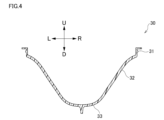
- FIG. 4 is a diagram illustrating the second preform.
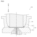
- FIG. 5 is a diagram illustrating an injection molding section.
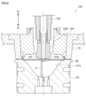
- FIG. 6 is a diagram illustrating the temperature adjustment unit.
- FIG. 7 is a diagram illustrating the temperature adjustment unit.
- FIG. 8 is a diagram illustrating the blow molding section.
- FIG. 9 is a diagram illustrating a method for manufacturing a resin container.
- the "upward and downward directions” and “leftward and rightward directions” will be mentioned as appropriate.
- the “upward and downward directions” are directions that include the “upward and downward directions.”
- the “leftward and rightward directions” are directions that include the “leftward and rightward directions.”
- the symbol U indicates the upward direction.
- the symbol D indicates the downward direction.
- the symbol L indicates the leftward direction.
- the symbol R indicates the rightward direction. Unless otherwise specified, the direction in which the openings of the first preform, the second preform, and the resin container are provided will be described as the upward direction.
- the manufacturing apparatus 100 is a blow molding apparatus that uses a hot parison method (one-stage blow molding method, injection stretch blow molding method), and includes an injection molding section 110, a temperature adjustment section 120, a blow molding section 130, and a removal section 140.
- the injection molding section 110 manufactures a first preform 20 (see FIG. 3) described below by injecting molten resin from an injection device 111.
- the temperature adjustment section 120 transforms the first preform 20 into a second preform 30 (see FIG. 4) described below, while adjusting the temperature of the second preform 30 to a temperature suitable for blow molding.
- the blow molding section 130 manufactures a resin container 10 by blow molding the second preform 30.
- the removal section 140 removes the resin container 10 manufactured by the blow molding section 130.
- the injection molding section 110, the temperature adjustment section 120, the blow molding section 130, and the removal section 140 are located at positions rotated a predetermined angle around the conveying means 150.
- the predetermined angle is 90 degrees.
- the conveying means 150 has a rotating plate (not shown).
- a neck mold 151 (see FIG. 5), which will be described later, is attached to the rotating plate.
- the neck mold 151 is configured to convey the first preform 20 and the second preform 30 to each of the injection molding section 110, the temperature adjustment section 120, the blow molding section 130, and the removal section 140 by rotating the rotating plate while holding the first preform 20 and the second preform 30.
- FIG. 2 illustrates a resin container 10 manufactured by the manufacturing apparatus 100 of this embodiment.
- the resin container 10 includes a container neck 11, a container body 12, and a container bottom 13.
- the container neck 11 forms the opening of the resin container 10.
- the container body 12 is connected to the container neck 11 and forms the side of the resin container 10.
- the container bottom 13 is connected to the container body 12 and closes one end of the container body 12.
- the first preform 20 includes an annular neck portion 21 and a body portion 22.
- the neck portion 21 includes at least one annular flange portion 211 that protrudes in the outer diameter direction from its outer circumferential surface.
- the flange portion 211 includes at least a first flange portion 211a that is disposed between the upper end of the neck portion 21 and the body portion 22, and, if necessary, a second flange portion 211b that is disposed at the upper end of the neck portion 21 and protrudes in the outer diameter direction.
- the first flange portion 211a is a portion that is supported by the neck mold 151 during manufacturing.
- the first flange portion 211a is a portion to which a lid or a seal member is fixed. It is desirable that the diameter of the second flange portion 211b is formed to be larger than the diameter of the first flange portion 211a.
- the body portion 22 is connected to the lower portion of the neck portion 21 and has a circular, approximately flat shape.
- the body 22 has at least a side portion 221 extending flush downward from the outer circumferential surface of the neck portion 21, a corner portion 222 located at the lower end of the side portion 221 and bending toward the inner diameter side, and a plate-shaped portion (flat portion) 223 extending horizontally from the corner portion 222.
- a gate portion which is a trace of a resin introduction hole of the injection cavity mold 114, may be provided at the center of the outer surface of the plate-shaped portion 223 of the body 22.
- the outer surface of the body 22 (more specifically, the plate-shaped portion 223) is preferably substantially horizontal, but may be curved (curved) in a shape that gently protrudes downward toward the gate portion.
- the inner surface of the body 22 is preferably substantially horizontal, but may be curved (curved) in a shape that gently protrudes downward toward the gate portion.
- the outer surface shape of the body 22 is approximately horizontal, it is desirable that the outer and inner surfaces of the body 22 are formed approximately parallel.
- the neck portion 21 constitutes the container neck portion 11 that forms the opening of the resin container 10.
- the body portion 22 constitutes the container body portion 12 and container bottom portion 13 of the resin container 10 by being blow molded.
- the first preform 20 is an example of a preform.
- the angle ⁇ between the central axis X of the neck portion 21 and the body portion 22 (or the outer surface or inner surface of the body portion 22 (more specifically, the plate-shaped portion 223)) is approximately 90° (the outer surface of the body portion 22 is regarded as a horizontal plane with no gate portion). In this case, the angle of the corners of the body portion 22 is also approximately 90°.
- the body portion 22 may be formed at an angle with respect to the central axis X. It is desirable that the angle between the central axis X of the neck portion 21 and the body portion 22 (or the outer surface or inner surface of the body portion 22) is 80° to 100°. In this case, it is desirable that the angle of the corners of the body portion 22 is also 80° to 100°.
- the shape of the first preform 20 is flat in the direction of the central axis X.
- the thickness of the body portion 22 (more specifically, the plate-shaped portion 223) of the first preform 20, excluding the gate portion is 2.0 mm or more and 6.0 mm or less, and furthermore, 3.0 mm or more and 5 mm or less.
- FIG. 4 illustrates the second preform 30.
- the second preform 30 is different from the first preform 20 in that the body 22 of the first preform 20 protrudes downward.
- the second preform 30 is substantially conical in shape.
- the second preform 30 may have a different shape from the second preform 30 in this embodiment as long as the shape is suitable for blow molding in the blow molding section 130.
- the second preform 30 is substantially conical in shape, and the thickness of the body wall 32 and the bottom wall 33 is smaller (thinner) than the thickness of the body 22 of the first preform 20.
- the shape and thickness of the neck 31 of the second preform 30 are the same as those of the neck 21 of the first preform 20.
- the material constituting the first preform 20, the second preform 30 and the resin container 10 is a thermoplastic synthetic resin, and can be appropriately selected according to the required specifications.
- Specific types of materials include, for example, PET (polyethylene terephthalate), PEN (polyethylene naphthalate), PCTA (polycyclohexane dimethylene terephthalate), Tritan (Tritan (registered trademark): a copolyester manufactured by Eastman Chemical Co.), PP (polypropylene), PE (polyethylene), PC (polycarbonate), PES (polyethersulfone), PPSU (polyphenylsulfone), PS (polystyrene), COP/COC (cyclic olefin polymer), PMMA (polymethyl methacrylate: acrylic), PLA (polylactic acid), and the like.
- additives such as coloring agents may be added to the materials.
- PET is the most preferable material for the first preform 20, the second preform 30 and the
- FIG. 5 illustrates an example of the injection molding section 110.
- the injection molding section 110 includes an injection molding die 112.
- the injection molding die 112 forms an injection cavity (molding space).
- the injection molding die 112 includes at least an injection molding core 113 and an injection cavity type 114.
- the injection molding die 112 may also include a neck type 151 that is also part of the conveying means 150 during molding (temporarily).
- the injection molding core 113 defines an injection cavity that mainly corresponds to the inner wall surface of the first preform 20.
- the injection cavity type 114, together with the neck type 151, defines an injection cavity that corresponds to the outer wall surface of the first preform 20.
- the neck mold 151 defines an injection cavity corresponding to the outer wall surface of the neck portion 21 of the first preform 20, and the injection cavity mold 114 defines an injection cavity corresponding to the outer wall surface of the body portion 22 of the first preform 20.
- the neck mold 151 defines an injection cavity corresponding to the flange portion 211 of the neck portion 21. More specifically, the neck mold 151 defines an injection cavity corresponding to the first flange portion 211a of the neck portion 21.
- the neck mold 151 and the injection molding core 113 define an injection cavity mold corresponding to the second flange portion 211b.
- the temperature control unit 120 includes a temperature control mold (temperature control pot type) 121, a cooling rod (first hollow rod member, temperature control rod) 122, and a fitting core (second hollow rod member) 124 that is in airtight contact with the neck portions 21 and 31 as temperature control mold members.
- the temperature control mold member may also include a neck mold 151 that is also part of the conveying means 150 during molding (temporarily).
- the temperature control mold 121 forms a temperature control cavity.
- the temperature control cavity corresponds to the shape of the outer wall surface of the second preform 30.
- the cooling rod 122 is configured to be displaceable in the vertical direction.
- the fitting core 124 is configured to contact the neck portions 21 and 31 of the first and second preforms 20 and 30 and introduce (supply) or extract (exhaust) compressed air of a predetermined pressure into the first preform 20 or the second preform 30.
- the cooling rod 122 includes a contact portion 123.
- the contact portion 123 is configured to contact at least a part of the inner wall surface of the first preform 20 and the second preform 30.
- the contact portion 123 is formed of a metal material with good heat conductivity, such as aluminum or an aluminum alloy.
- a first vent 123a is formed in the contact portion 123 of the cooling rod 122.
- the first vent 123a is configured to introduce (supply) compressed air of a predetermined pressure through the inside of the cooling rod 122 to the first preform 20 or the second preform 30.
- a second vent 123b is formed between the cooling rod 122 and the fitting core 124.
- the second vent 123b is configured to lead (exhaust) the compressed air from the first preform 20 or the second preform 30.
- the cooling rod 122 is an example of a deformation portion.
- the temperature adjustment unit 120 may be configured to introduce compressed air at a predetermined pressure into the first preform 20 or the second preform 30 through the second ventilation port 123b and exhaust the air through the first ventilation port 123a.
- the blow molding section 130 includes a blow molding die (blow die) 131, a stretch rod 132, and a blow core die (blow nozzle) 133 for introducing and discharging blow air as blow molding die members.
- the blow molding die members may also include a neck die 151 that is also part of the conveying means 150 during molding (temporarily).
- the blow molding die 131 is configured to determine the shape of the resin container 10.
- the blow molding die 131 includes a pair of openable and closable blow cavity dies 131a that determine the shape of the container body 12 of the resin container 10, and a bottom die 131b that determines the shape of the container bottom 13 of the resin container 10.
- the stretch rod 132 is configured to be displaceable in the vertical direction.
- the stretch rod 132 is configured to come into contact with the second preform 30 transported to the blow molding section 130 and stretch the second preform 30 downward.
- the blow core 133 abuts against the neck portion 31 and is responsible for introducing (supplying) and discharging (exhausting) blow air into the second preform 30.
- FIG. 9 illustrates an example of the method for manufacturing a resin container.
- the method for manufacturing a resin container is a method that uses a hot parison method, and includes at least an injection molding process S1, a temperature control process S2, and a blow molding process S3.
- the manufacturing method of this embodiment further includes a container removal process S4.
- the injection molding process S1 includes injecting molten resin into an injection cavity formed by an injection mold 112 to form a first preform 20.
- the molten resin injected into the injection cavity by the injection device 111 of the injection mold 112 is cooled by the injection mold 112 to form the first preform 20.
- the first preform 20 may be released from the injection mold 112 at a high temperature.
- the cooling time is set to 1/2 or less of the filling time, preferably 1/3 or less, and more preferably 0 seconds, and the first preform 20 is released from the injection mold 112 in a state where the heat retention is high.
- the first preform 20 released from the injection mold 112 is transported to the temperature adjustment unit 120 while being held by the neck mold 151.
- the temperature control step S2 includes adjusting the temperature to a temperature suitable for blow molding while deforming the first preform 20 into the second preform 30.
- the temperature control step S2 further includes forming the second preform 30 by stretching the first preform 20 and contacting it with the inner wall surface 121a of the temperature control cavity formed by the temperature control mold 121.
- the temperature control step S2 includes a step (pre-blow step) of contacting the first preform 20 with the inner wall surface 121a of the temperature control cavity by displacing (lowering) the cooling rod 122 in contact with the body portion 22 of the first preform 20 and ejecting compressed air from the first air vent 123a or the second air vent 123b.
- the temperature control process S2 of this embodiment includes a process of cooling the second preform 30 after the second preform 30 is formed, in which compressed air for cooling is introduced into the second preform 30 through the second vent 123b or the first vent 123a while being exhausted from the first vent 123a or the second vent 123b (cooling blow process).
- the directions of the compressed air flow in the preliminary blow process and the cooling blow process may be set to be opposite to each other.
- the first preform 20 transported from the injection molding section 110 to the temperature control section 120 comes into contact with the abutment section 123, and is stretched by the cooling rod 122 displacing downward.
- the stretching of the first preform 20 by the cooling rod 122 is sometimes called preliminary stretching.
- the downward displacement (descent) of the cooling rod 122 is performed until the first preform 20 reaches a position near the bottom end of the inner wall surface 121a of the temperature control cavity defined by the temperature control mold 121 (to the extent that it does not come into contact with the inner wall surface 121a) (white arrow A).
- the preliminary stretching causes the first preform 20 to be significantly stretched in the vertical axis direction, and the first preform 20 is deformed into a shape similar to that of the second preform 30.
- the cooling rod 122 stops displacing (descent). At this time, a gap is formed between the outer surface (bottom) of the lower side of the drawn first preform 20 and the inner wall surface 121a.
- the vicinity of the gate of the first preform 20 is cooled from the inside by contact with the abutment portion 123.
- the body portion 22 of the first preform 20 becomes thinner while dissipating heat due to the preliminary drawing, so the temperature drops (it is cooled).
- compressed air is introduced from the first vent 123a formed in the abutment portion 123 of the cooling rod 122.
- the second vent 123b is closed.
- the pre-stretched first preform 20 further expands and comes into contact with the temperature-controlling die 121 to take the shape of the second preform 30 (pre-blow process).
- the second vent 123b is opened, and the compressed air continues to flow, and the introduced compressed air passes through the outside of the cooling rod 122 and is discharged from the second vent 123b. Therefore, the outside of the second preform 30 is cooled by contacting the temperature-controlling die 121, and the inside of the second preform 30 is cooled by the continued flow of compressed air (cooling blow process).
- the first preform 20 can be cooled at high speed when it is deformed into the shape of the second preform 30.
- the second preform 30 cooled to a temperature suitable for blow molding in the temperature control section 120 is transported to the blow molding section 130 while being held by the neck mold 151.
- the blow molding process S3 includes blow molding the second preform 30 to produce the resin container 10.
- the blow molding process S3 of this embodiment further includes stretching the second preform 30 by displacing the stretch rod 132.
- the second preform 30 transported from the temperature adjustment section 120 is housed in a blow molding die 131 and stretched downward by contact with a stretch rod 132.
- the second preform 30 is then blow molded by introducing blow air (compressed air) into the interior of the second preform 30 from the neck portion 21 of the second preform 30 via a blow core 133.
- the second preform 30 is deformed by blow molding into a shape corresponding to the inner wall surface of the blow cavity defined by the blow molding die 131, and becomes a resin container 10.
- the manufactured resin container is transported to the removal section 140 while being held by the neck mold, and is removed from the manufacturing apparatus 100 in a container removal process S4.
- the blow air is set to a higher pressure than the compressed air used in the temperature adjustment process S2 in order to improve shaping properties.
- the preform is designed to have an optimal shape, taking into consideration the size, shape, specifications, degree of stretching, etc. of the resin container. If the stretch ratio of the preform is excessively high when blow molded, defects may occur in which the container cannot be molded into the desired shape and thickness distribution even after blow molding. For this reason, in the case of the container of this embodiment, the preform is conventionally designed to be approximately conical (similar in shape to the second preform), for example.
- the angle ⁇ between the central axis X of the neck portion 21 and the body portion 22 (or the angle of the corner portion 222) is 80° to 100°, and the body portion 22 is thick enough to ensure that injection molding is not hindered and that the heat reserve required for blow molding is secured.
- the amount of resin (volume) of the entire preform can be suppressed while providing a thickness suitable for injection molding and securing the heat reserve required for blow molding.
- the first preform 20 is manufactured so that the angle between the central axis X of the neck portion 21 and the body portion 22 (angle of the corner portion 222) is 80° to 100°. While such a flattened first preform 20 has the necessary thickness for injection molding, the amount of resin (volume) of the entire first preform 20 is suppressed.
- a lightweight resin container 10 is provided by manufacturing the first preform 20 from such a first preform 20. Since the first preform 20 does not have a shape suitable for the resin container 10 that is finally manufactured, simply blow molding the first preform 20 may result in an excessively high stretch ratio, and the resin container 10 may not be molded well.
- the first preform 20 is stretched to become the second preform 30. Therefore, compared to when the resin container 10 is manufactured from the first preform 20, the stretching ratio is reduced when the resin container 10 is manufactured from the second preform 30, and the resin container 10 is easily manufactured satisfactorily.
- This provides a manufacturing method and manufacturing device 100 for the resin container 10 that achieves both weight reduction and suppression of manufacturing defects of the resin container 10.
- the body 22 is manufactured to have a thickness of 5 mm or less.
- the resin container 10 manufactured from such a preform is lighter. Furthermore, according to the manufacturing method and manufacturing device 100 for the resin container 10 configured as described above, the resin container 10 can be manufactured well from the lightweight preform as described above.
- the first preform 20 is released from the injection molding die 112 at a high temperature.
- the cooling time for the molten resin in the injection molding step S1 is shortened, and the cycle time for manufacturing the resin container 10 is also shortened.
- the transformation from the first preform 20 to the second preform 30 can be performed with a simple configuration.
- the temperature adjustment step S2 includes introducing cooling air into the interior of the second preform 30 through the first ventilation hole 123a formed in the cooling rod 122. Therefore, in the temperature adjustment step S2, compressed air can be introduced into the interior of the second preform 30 through the first ventilation hole 123a formed in the cooling rod 122. If the preform is slowly cooled in the temperature adjustment step S2, poor appearance such as whitening may occur. The exterior of the second preform 30 is cooled by contact with the inner wall surface 121a of the temperature adjustment cavity, and the interior of the second preform 30 is cooled by the introduction of compressed air and convection, so the cooling speed of the second preform 30 is improved.
- the first preform 20 has been described in which the angle ⁇ between the central axis X of the neck portion 21 and the body portion 22 is approximately 90°, but the shape of the first preform 20 is not limited to the example of this embodiment, and the angle ⁇ between the central axis X of the neck portion 21 and the body portion 22 may be appropriately selected in the range of 80° to 100°.
- the angle ⁇ between the central axis X of the neck portion 21 and the body portion 22 is 100°
- the body portion 22 of the first preform 20 has a shape that protrudes downward from the lower end of the neck portion 21.
- the angle ⁇ between the central axis X of the neck portion 21 and the body portion 22 is 80°
- the body portion 22 of the first preform 20 has a shape that protrudes upward from the lower end of the neck portion 21.
- the thickness of the body 22 of the first preform 20 does not have to be uniform.
- the thickness of the body 22 near the neck 21 may be greater than the thickness near the center of the body 22. This makes it easier to retain heat in the body near the neck 21, which is particularly prone to cooling in the first preform 20.
Landscapes
- Engineering & Computer Science (AREA)
- Mechanical Engineering (AREA)
- Manufacturing & Machinery (AREA)
- Physics & Mathematics (AREA)
- Geometry (AREA)
- Thermal Sciences (AREA)
- Blow-Moulding Or Thermoforming Of Plastics Or The Like (AREA)
Priority Applications (4)
| Application Number | Priority Date | Filing Date | Title |
|---|---|---|---|
| JP2024566136A JPWO2024135783A1 (https=) | 2022-12-21 | 2023-12-21 | |
| KR1020257023836A KR20250124343A (ko) | 2022-12-21 | 2023-12-21 | 프리폼, 수지제 용기의 제조 방법, 및 수지제 용기의 제조 장치 |
| CN202380091651.3A CN120530007A (zh) | 2022-12-21 | 2023-12-21 | 预成型坯、树脂制容器的制造方法以及树脂制容器的制造装置 |
| EP23907143.4A EP4640406A1 (en) | 2022-12-21 | 2023-12-21 | Preform, method for producing resin container, and device for producing resin container |
Applications Claiming Priority (2)
| Application Number | Priority Date | Filing Date | Title |
|---|---|---|---|
| JP2022-204775 | 2022-12-21 | ||
| JP2022204775 | 2022-12-21 |
Publications (1)
| Publication Number | Publication Date |
|---|---|
| WO2024135783A1 true WO2024135783A1 (ja) | 2024-06-27 |
Family
ID=91588975
Family Applications (1)
| Application Number | Title | Priority Date | Filing Date |
|---|---|---|---|
| PCT/JP2023/045973 Ceased WO2024135783A1 (ja) | 2022-12-21 | 2023-12-21 | プリフォーム、樹脂製容器の製造方法、および樹脂製容器の製造装置 |
Country Status (5)
| Country | Link |
|---|---|
| EP (1) | EP4640406A1 (https=) |
| JP (1) | JPWO2024135783A1 (https=) |
| KR (1) | KR20250124343A (https=) |
| CN (1) | CN120530007A (https=) |
| WO (1) | WO2024135783A1 (https=) |
Citations (5)
| Publication number | Priority date | Publication date | Assignee | Title |
|---|---|---|---|---|
| JPH11240064A (ja) * | 1997-11-28 | 1999-09-07 | Aoki Katashi Kenkyusho:Kk | 射出延伸ブロー成形によるペイント容器等の広口容器 |
| JP2003001697A (ja) * | 2001-06-27 | 2003-01-08 | Tachibana Yoki Kk | 射出ブロー成形容器の製造方法及び射出ブロー成形容器 |
| JP2006062353A (ja) * | 2004-07-27 | 2006-03-09 | Toyo Seikan Kaisha Ltd | フランジ部の加熱処理方法、フランジ部の加熱処理装置及びフランジ付き樹脂製容器の製造方法 |
| JP2010188711A (ja) * | 2009-02-20 | 2010-09-02 | Frontier:Kk | 底付き筒状容器の製造方法 |
| WO2021221024A1 (ja) | 2020-04-27 | 2021-11-04 | 日精エー・エス・ビー機械株式会社 | 樹脂製広口容器の製造方法、製造装置および樹脂製広口容器 |
-
2023
- 2023-12-21 CN CN202380091651.3A patent/CN120530007A/zh active Pending
- 2023-12-21 EP EP23907143.4A patent/EP4640406A1/en active Pending
- 2023-12-21 WO PCT/JP2023/045973 patent/WO2024135783A1/ja not_active Ceased
- 2023-12-21 KR KR1020257023836A patent/KR20250124343A/ko active Pending
- 2023-12-21 JP JP2024566136A patent/JPWO2024135783A1/ja active Pending
Patent Citations (5)
| Publication number | Priority date | Publication date | Assignee | Title |
|---|---|---|---|---|
| JPH11240064A (ja) * | 1997-11-28 | 1999-09-07 | Aoki Katashi Kenkyusho:Kk | 射出延伸ブロー成形によるペイント容器等の広口容器 |
| JP2003001697A (ja) * | 2001-06-27 | 2003-01-08 | Tachibana Yoki Kk | 射出ブロー成形容器の製造方法及び射出ブロー成形容器 |
| JP2006062353A (ja) * | 2004-07-27 | 2006-03-09 | Toyo Seikan Kaisha Ltd | フランジ部の加熱処理方法、フランジ部の加熱処理装置及びフランジ付き樹脂製容器の製造方法 |
| JP2010188711A (ja) * | 2009-02-20 | 2010-09-02 | Frontier:Kk | 底付き筒状容器の製造方法 |
| WO2021221024A1 (ja) | 2020-04-27 | 2021-11-04 | 日精エー・エス・ビー機械株式会社 | 樹脂製広口容器の製造方法、製造装置および樹脂製広口容器 |
Non-Patent Citations (1)
| Title |
|---|
| See also references of EP4640406A1 |
Also Published As
| Publication number | Publication date |
|---|---|
| EP4640406A1 (en) | 2025-10-29 |
| CN120530007A (zh) | 2025-08-22 |
| KR20250124343A (ko) | 2025-08-19 |
| JPWO2024135783A1 (https=) | 2024-06-27 |
Similar Documents
| Publication | Publication Date | Title |
|---|---|---|
| KR102398863B1 (ko) | 수지제 용기의 제조방법, 금형 유닛 및 성형기 | |
| JP6679060B2 (ja) | 射出延伸ブロー成形機の射出成形型とプリフォームの成形方法、及び容器の成形方法 | |
| EP3919254A1 (en) | Production device and production method for resin containers | |
| US11958230B2 (en) | Method for producing resin container and device for producing resin container | |
| CN112088081A (zh) | 吹塑方法、吹塑模具以及吹塑设备 | |
| JP2024164288A (ja) | 樹脂製容器の製造装置、樹脂製容器の製造方法、および金型 | |
| US20220134629A1 (en) | Off-center container manufacturing method and temperature adjustment mold | |
| KR101975682B1 (ko) | 중공 용기의 사출 블로우 성형 방법 및 사출 블로우 성형 장치 | |
| US12318989B2 (en) | Method for manufacturing resin wide-mouthed container, manufacturing device, and resin wide-mouthed container | |
| WO2024135783A1 (ja) | プリフォーム、樹脂製容器の製造方法、および樹脂製容器の製造装置 | |
| JP5789556B2 (ja) | 二重容器の製造方法 | |
| JP7673093B2 (ja) | 樹脂製容器の製造方法および製造装置 | |
| EP4640407A1 (en) | Preform, injection molding mold, temperature controlling mold, resin container manufacturing method, and resin container manufacturing device | |
| EP4324620A1 (en) | Production method and production device for resin container | |
| EP4470751A1 (en) | Temperature regulating mold and method for producing resin container | |
| WO2024143537A1 (ja) | 樹脂製容器の製造装置、樹脂製容器の製造方法、および温度調整用金型 | |
| JPWO2024135783A5 (https=) | ||
| CN119704628A (zh) | 一种塑料瓶吹塑成型设备及方法 |
Legal Events
| Date | Code | Title | Description |
|---|---|---|---|
| 121 | Ep: the epo has been informed by wipo that ep was designated in this application |
Ref document number: 23907143 Country of ref document: EP Kind code of ref document: A1 |
|
| WWE | Wipo information: entry into national phase |
Ref document number: 2024566136 Country of ref document: JP |
|
| ENP | Entry into the national phase |
Ref document number: 1020257023836 Country of ref document: KR Free format text: ST27 STATUS EVENT CODE: A-0-1-A10-A15-NAP-PA0105 (AS PROVIDED BY THE NATIONAL OFFICE) |
|
| WWE | Wipo information: entry into national phase |
Ref document number: 1020257023836 Country of ref document: KR Ref document number: 202517067873 Country of ref document: IN Ref document number: 202380091651.3 Country of ref document: CN |
|
| WWE | Wipo information: entry into national phase |
Ref document number: 2023907143 Country of ref document: EP |
|
| NENP | Non-entry into the national phase |
Ref country code: DE |
|
| ENP | Entry into the national phase |
Ref document number: 2023907143 Country of ref document: EP Effective date: 20250721 |
|
| WWP | Wipo information: published in national office |
Ref document number: 202517067873 Country of ref document: IN |
|
| ENP | Entry into the national phase |
Ref document number: 2023907143 Country of ref document: EP Effective date: 20250721 |
|
| ENP | Entry into the national phase |
Ref document number: 2023907143 Country of ref document: EP Effective date: 20250721 |
|
| WWP | Wipo information: published in national office |
Ref document number: 1020257023836 Country of ref document: KR |
|
| WWP | Wipo information: published in national office |
Ref document number: 202380091651.3 Country of ref document: CN |
|
| WWP | Wipo information: published in national office |
Ref document number: 2023907143 Country of ref document: EP |