WO2024135731A1 - 電磁弁及び電磁弁付き膨張弁 - Google Patents
電磁弁及び電磁弁付き膨張弁 Download PDFInfo
- Publication number
- WO2024135731A1 WO2024135731A1 PCT/JP2023/045716 JP2023045716W WO2024135731A1 WO 2024135731 A1 WO2024135731 A1 WO 2024135731A1 JP 2023045716 W JP2023045716 W JP 2023045716W WO 2024135731 A1 WO2024135731 A1 WO 2024135731A1
- Authority
- WO
- WIPO (PCT)
- Prior art keywords
- valve
- solenoid valve
- solenoid
- valve body
- chamber
- Prior art date
- Legal status (The legal status is an assumption and is not a legal conclusion. Google has not performed a legal analysis and makes no representation as to the accuracy of the status listed.)
- Ceased
Links
Images


Classifications
-
- F—MECHANICAL ENGINEERING; LIGHTING; HEATING; WEAPONS; BLASTING
- F16—ENGINEERING ELEMENTS AND UNITS; GENERAL MEASURES FOR PRODUCING AND MAINTAINING EFFECTIVE FUNCTIONING OF MACHINES OR INSTALLATIONS; THERMAL INSULATION IN GENERAL
- F16K—VALVES; TAPS; COCKS; ACTUATING-FLOATS; DEVICES FOR VENTING OR AERATING
- F16K31/00—Actuating devices; Operating means; Releasing devices
- F16K31/001—Actuating devices; Operating means; Releasing devices actuated by volume variations caused by an element soluble in a fluid or swelling in contact with a fluid
-
- F—MECHANICAL ENGINEERING; LIGHTING; HEATING; WEAPONS; BLASTING
- F16—ENGINEERING ELEMENTS AND UNITS; GENERAL MEASURES FOR PRODUCING AND MAINTAINING EFFECTIVE FUNCTIONING OF MACHINES OR INSTALLATIONS; THERMAL INSULATION IN GENERAL
- F16K—VALVES; TAPS; COCKS; ACTUATING-FLOATS; DEVICES FOR VENTING OR AERATING
- F16K31/00—Actuating devices; Operating means; Releasing devices
- F16K31/02—Actuating devices; Operating means; Releasing devices electric; magnetic
- F16K31/06—Actuating devices; Operating means; Releasing devices electric; magnetic using a magnet, e.g. diaphragm valves, cutting off by means of a liquid
Definitions
- the present invention relates to a solenoid valve and an expansion valve with a solenoid valve.
- An expansion valve with a solenoid valve which is one type of valve device, is used, for example, in a refrigeration cycle having multiple evaporators connected in parallel, and has a function to control the degree of superheat of the refrigerant on the outlet side of the evaporator as well as a function to shut off the circuit in the refrigeration cycle.
- Patent Document 1 discloses a configuration in which an expansion valve has a valve port in a communication passage that connects a primary passage through which high-pressure refrigerant flows and an expansion valve chamber, and a solenoid valve is attached to open or close the valve port.
- the valve part fixed to the tip of the plunger abuts against or separates from the valve orifice that protrudes in a cylindrical shape from the valve body side, thereby opening or closing the valve orifice.
- the disk-shaped valve part is inserted into a recess at the tip of the plunger, and the valve part is fixed to the plunger by bending the crimped part that protrudes from the plunger toward the valve orifice side toward the valve part (see Figure 4 of Patent Document 1).
- the crimped part acts as a resistance to the flow and may generate turbulence, reducing the flow rate of the refrigerant passing through the valve orifice.
- the present invention was made in consideration of the above problems, and aims to provide a solenoid valve and an expansion valve with a solenoid valve that can ensure a smooth flow of fluid when the valve is open.
- the solenoid valve of the present invention comprises: a valve body including a solenoid valve chamber, an inlet side flow passage communicating with the solenoid valve chamber, a recess, and an outlet side flow passage formed on a bottom surface of the recess; a first valve portion including a valve hole connecting the outlet side flow path and the solenoid valve chamber, the first valve portion being attached to the recess of the valve body by any one of press-fitting, bonding, screw fixing, and snap-fitting; a second valve portion that is seated against the first valve portion to block the valve hole and that is separated from the first valve portion to open the valve hole, the first valve portion and the second valve portion are made of materials having different Young's moduli; a surface of the second valve portion facing the first valve portion is formed of a single member; when an end of the first valve portion is projected toward the second valve portion along an axial direction of the valve hole at least between the inlet side flow path and the outlet side flow path in the solenoid valve chamber, the projected image does not overlap with the
- the solenoid valve of the present invention further comprises: a valve body including a solenoid valve chamber, an inlet side flow passage connecting a flow passage on a downstream side of the valve chamber and the solenoid valve chamber, a recess, and an outlet side flow passage formed on a bottom surface of the recess; a first valve portion including a valve hole connecting the outlet side flow path and the solenoid valve chamber, the first valve portion being attached to the recess of the valve body by any one of press-fitting, bonding, screw fixing, and snap-fitting; a second valve portion that is seated against the first valve portion to block the valve hole and that is separated from the first valve portion to open the valve hole, the first valve portion and the second valve portion are made of materials having different Young's moduli; a surface of the second valve portion facing the first valve portion is formed of a single member;
- the present invention is characterized in that, when an end of the first valve portion is projected toward the second valve portion along the axial direction of the valve hole
- the present invention provides a solenoid valve and an expansion valve with a solenoid valve that ensures a smooth flow of fluid when the valve is open.
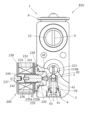
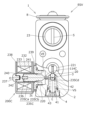
- FIG. 1 is a schematic cross-sectional view showing a solenoid-valve-equipped expansion valve according to a first embodiment.
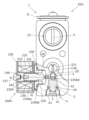
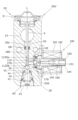
- FIG. 2 is a vertical cross-sectional view of the solenoid-valve-equipped expansion valve in a cross section shifted in phase by 90 degrees around the axis L from FIG.
- FIG. 3 is a bottom view of the configuration of FIG. 2 cut along line AA.
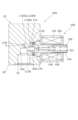
- FIG. 4 is an enlarged cross-sectional view showing the vicinity of the solenoid valve chamber.
- FIG. 5 is a schematic cross-sectional view similar to FIG. 2, showing an expansion valve with a solenoid valve according to a second embodiment.
- FIG. 6 is an enlarged cross-sectional view similar to FIG. 4 of a solenoid-valve-equipped expansion valve according to the second embodiment.
- FIG. 7 is a schematic cross-sectional view similar to FIG. 2, showing an expansion valve with a solenoid valve according to a third embodiment.
- FIG. 8 is an enlarged cross-sectional view similar to FIG. 4 of a solenoid-valve-equipped expansion valve according to a third embodiment.
- FIG. 9 is a schematic cross-sectional view similar to FIG. 2, showing an expansion valve with a solenoid valve according to a fourth embodiment.
- FIG. 10 is an enlarged cross-sectional view similar to FIG. 4 of a solenoid-valve-equipped expansion valve according to the fourth embodiment.
- FIG. 11 is a schematic cross-sectional view similar to FIG. 2, showing an expansion valve with a solenoid valve according to the fifth embodiment.
- FIG. 12 is an enlarged cross-sectional view similar to FIG. 4 of a solenoid-valve-equipped expansion valve according to the fifth embodiment.
- FIG. 13 is a schematic cross-sectional view similar to FIG. 2, showing an expansion valve with a solenoid valve according to the sixth embodiment.
- FIG. 14 is an enlarged cross-sectional view similar to FIG. 4 of a solenoid-valve-equipped expansion valve according to the sixth embodiment.
- FIG. 15 is a schematic cross-sectional view similar to FIG. 2, showing an expansion valve with a solenoid valve according to the seventh embodiment.
- FIG. 16 is an enlarged cross-sectional view similar to FIG. 4 of a solenoid-valve-equipped expansion valve according to the seventh embodiment.
- FIG. 17 is a schematic cross-sectional view similar to FIG.
- FIG. 18 is an enlarged cross-sectional view similar to FIG. 4 of a solenoid-valve-equipped expansion valve according to the eighth embodiment.
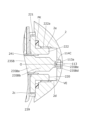
- FIG. 19 is an enlarged cross-sectional view similar to FIG. 1 of a solenoid-valve-equipped expansion valve according to the ninth embodiment.
- FIG. 20 is a side view of the configuration of FIG. 19 , cut along line BB except for the solenoid valve and its vicinity, and cut along line CC of the solenoid valve and its vicinity.
- FIG. 21 is a bottom view of the configuration of FIG. 19 taken along line DD.
- the solenoid valve-equipped expansion valve ESV comprises an expansion valve unit (also called an expansion valve) 1 and a solenoid valve unit (also called a solenoid valve) 100, but uses a valve body 2 in common.
- FIG. 1 is a schematic cross-sectional view showing a solenoid valve-equipped expansion valve ESV according to the present embodiment.
- FIG. 1 is a schematic cross-sectional view showing a solenoid valve-equipped expansion valve ESV according to the present embodiment.
- the expansion valve unit 1 comprises a valve body 2 having an expansion valve chamber VS, a valve body 3, a biasing device 4, an actuating rod 5, a ring spring 6, and a power element 8.
- the axis of the expansion valve unit 1 is L.
- the valve body 2 includes a first flow path 21, a second flow path 22, and a return flow path 23 in addition to the expansion valve chamber VS.
- the first flow path 21 is a supply side flow path, and a refrigerant (also called a fluid) is supplied to the expansion valve chamber VS via the supply side flow path.
- the second flow path 22 is a discharge side flow path, and the fluid in the expansion valve chamber VS is discharged to the outside of the expansion valve via the working rod insertion hole 27, the intermediate passage 22a, and the discharge side flow path.
- the first flow path 21 and the expansion valve chamber VS are connected via an inlet side flow path 112 and an outlet side flow path 113 ( Figure 3) described later.
- the spherical valve element 3 is disposed within the expansion valve chamber VS.
- the valve element 3 When the valve element 3 is seated on the annular valve seat 20 of the valve body 2, the expansion valve chamber VS and the second flow path 22 are not in communication with each other.
- the valve element 3 when the valve element 3 is separated from the valve seat 20, the expansion valve chamber VS and the second flow path 22 are in communication with each other.
- the actuating rod 5 can also press the valve body 3 in the valve opening direction against the biasing force of the biasing device 4.
- the actuating rod 5 extends along the axis L from the valve body 3 to the power element 8 through the actuating rod insertion hole 27, the central hole 28, the annular portion 26, the return flow passage 23, and the communication passage 2b, which are formed coaxially in the valve body 2.
- the inner diameter of the annular portion 26 is larger than the inner diameter of the central hole 28, which slidably holds the actuating rod 5.
- An actuating rod vibration isolation spring 6, which has a vibration isolation function for the actuating rod 5, is arranged in the annular portion 26.
- the actuating rod vibration-proof spring 6 is described in detail in, for example, JP 2018-25332 A, so a detailed description will be omitted here.
- the power element 8 is attached to a recess 2a provided at the top of the valve body 2.
- the recess 2a is connected via a communication passage 2b to a return flow path 23 through which the refrigerant from the evaporator passes.
- the power element 8 has a plug 81, an upper cover member 82, a diaphragm 83, a stopper member 84, and a receiving member 86.
- a hole 82a is formed at the top of the upper cover member 82, which can be sealed with a plug 81.
- the diaphragm 83 is made of a thin plate material with multiple concentric circular projections and recesses.
- the stopper member 84 has a disk portion and a cylindrical portion that is coaxially connected to the underside of the disk portion, and a fitting hole 84c is formed in the center of the lower end of the cylindrical portion.
- the receiving member 86 has a flange portion with an outer diameter approximately the same as the outer diameter of the top cover member 82, and a hollow cylindrical portion connected to the lower end of the flange portion, and a male thread 86c is formed on the outer periphery of the hollow cylindrical portion.
- the outer peripheries of the upper cover member 82, the diaphragm 83, and the flange portion of the receiving member 86 are overlapped, and then the outer peripheries are circumferentially welded together by, for example, TIG welding, laser welding, plasma welding, etc.
- the working gas is injected into the space surrounded by the top cover member 82 and the diaphragm 83 (called the pressure actuated chamber PA) through the hole 82a formed in the top cover member 82, and the hole 82a is then sealed with a plug 81, which is then fixed to the top cover member 82 using projection welding or the like.
- the diaphragm 83 is pressurized by the working gas sealed in the pressure actuated chamber PA in such a way that it bulges towards the receiving member 86, and is supported by abutting against the upper surface of the stopper member 84, which is disposed in the lower space LS surrounded by the diaphragm 83 and the receiving member 86.
- the stopper member 84 since the disk portion of the stopper member 84 is held by the receiving member 86, the stopper member 84 will not come out of the power element 8.
- the actuating rod 5 When assembling the power element 8 to the valve body 2, with the upper end of the actuating rod 5 fitted into the fitting hole 84c of the stopper member 84, the actuating rod 5 is inserted into the valve body 2 while passing through the actuating rod vibration-proof spring 6 attached to the valve body 2. Furthermore, the male thread 86c of the receiving member 86 is screwed into the female thread of the recess 2a of the valve body 2, and the power element 8 is fixed to the valve body 2 by screwing it in. The gap between the valve body 2 and the power element 8 is sealed by a packing PK. In this state, the lower space LS of the power element 8 communicates with the return flow path 23, i.e., they have the same internal pressure.
- the biasing device 4 has a coil spring 41 made of circular wire wound in a spiral shape, a valve body support 42 attached to the upper end of the coil spring 41 and supporting the valve body 3, and a spring receiving member 43 that supports the lower end of the coil spring 41 and is attached to the valve body 2.
- the spring receiving member 43 has the function of sealing the expansion valve chamber VS of the valve body 2, and supporting the end of the coil spring 41 that biases the valve body 3 toward the valve seat 20.
- the spherical valve body 3 is welded to the top surface of the valve body support 42, and the two are integrated.
- the solenoid valve unit 100 of this embodiment is a so-called pilot type solenoid valve unit.
- FIG. 2 is a longitudinal cross-sectional view of the solenoid valve-equipped expansion valve ESV in a cross section shifted in phase by 90 degrees around the axis L from FIG. 1.
- FIG. 3 is a bottom view of the configuration of FIG. 1 cut along line A-A.
- the axis of the solenoid valve unit 100 is O.
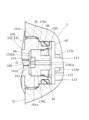
- FIG. 4 is an enlarged cross-sectional view showing the vicinity of the solenoid valve chamber VE.
- the solenoid valve unit 100 has a valve body 2, an attractor 140, a plunger 150, a pilot valve body 160, a main valve body 170, and a coil unit 180.
- the attractor 140 and the coil unit 180 form the drive unit.
- the axis of the solenoid valve unit 100 is O.
- valve body 2 Inside the valve body 2, there is an inlet side flow passage 112 ( Figure 3) connected to the first flow passage 21, an outlet side flow passage 113 connected to the expansion valve chamber VS, and a cylindrical solenoid valve chamber VE communicating with the inlet side flow passage 112 and the outlet side flow passage 113.
- inlet side flow passage 112 Figure 3
- outlet side flow passage 113 connected to the expansion valve chamber VS
- cylindrical solenoid valve chamber VE communicating with the inlet side flow passage 112 and the outlet side flow passage 113.
- an annular recess 113a is formed at the end of the outlet side flow passage 113 on the solenoid valve chamber VE side.
- the outlet side flow passage 113 is formed on the bottom surface of the recess 113a (similar to the embodiment described later).
- a circular tube member 114 made of PTFE or rubber is attached to the recess 113a by press-fitting or bonding. The inside of the circular tube member 114 becomes a valve hole connecting the solenoid valve chamber VE and the outlet side flow passage 113.
- the outer diameter of the end of the circular tube member 114 on the recess 113a side is equal to the inner diameter of the recess 113a, and the total length of the circular tube member 114 is longer than the depth of the recess 113a. Therefore, when attached to the recess 113, the tip of the circular tube member 114 protrudes into the solenoid valve chamber VE.
- the inner diameter of the circular tube member 114 is uniform and equal to the inner diameter of the outlet side flow passage 113. It is preferable that the inner diameter at the tip side is smaller than the outer diameter of the end of the recess 113a side of the circular pipe member 114.
- the tip shape of the circular pipe member 114 is gradually reduced in diameter on the outer side toward the tip, and gradually expanded in diameter on the inner diameter side toward the tip.
- the cross section of the outer wall tip has an arc shape.
- the circular pipe member 114 becomes the first valve portion having a tip that abuts in line contact with the flat end surface of the main valve body 170.
- the mounting surface 2c which forms the side surface of the valve body 2, is a plane perpendicular to the axis O.
- a circular recess 2d opens into the mounting surface 2c coaxially with the axis O.
- the circular recess 2d is a stepped opening, and a female thread 2e is formed on the mounting surface side, and a solenoid valve chamber VE is formed at the back of the circular recess 2d.
- the suction element 140 is composed of a disk-shaped base 141 and a shaft portion 142 that is smaller in diameter than the base 141 and is coaxially connected to the base 141.
- the base 141 has a circular opening 141a formed in the center of the end portion on the valve body side.
- a guide hole 141b that penetrates in the direction of the axis O is formed between the base 141 and the shaft portion 142 so as to communicate with the center of the opening 141a.
- a disk-shaped main valve body 170 is arranged so as to be slidable along the axis O.
- a pilot valve hole 170a is formed penetrating the center of the main valve body 170 made of brass in the direction of the axis O, and an annular recess 170b is formed at the end of the pilot valve hole 170a on the guide hole 141b side.
- An annular member 171 made of PTFE or rubber is attached by press-fitting or bonding to the recess 170b. In other words, the annular member 171 is not fixed to the main valve body 170 by crimping.
- the projected image does not overlap with the main valve body 170.
- the outer diameter of the annular member 171 is equal to the inner diameter of the recess 170b, and the thickness of the annular member 171 is approximately equal to the depth of the recess 170b.
- the inner diameter of the annular member 171 is approximately equal to the inner diameter of the pilot valve hole 170a.
- the surface of the main valve body 170 facing the circular pipe member 114 is composed of a single member (as in the embodiment described below).
- the end surface of the main valve body (second valve portion) 170 facing the valve body is flat and can be seated on the tip of the circular pipe member 114.
- a pressure equalizing passage (not shown) that penetrates along the axis O is formed adjacent to the pilot valve hole 170a, but the pressure equalizing passage does not necessarily have to be formed.
- the main valve body 170 is biased toward the shaft portion 142 side against the edge of the base portion 141 of the suction element 140 by a partial conical spring 173.
- the suction element 140 By screwing the male thread 141c formed on the outer periphery of the base 141 into the female thread 2e formed on the inner periphery of the circular recess 2d, the suction element 140 is fixed to the valve body 2 while its outer periphery abuts against the inner periphery step of the circular recess 2d, thereby forming a solenoid valve chamber VE inside the circular recess 2d.
- an O-ring OR is placed between the base 141 and the circular recess 2d to prevent refrigerant from leaking from the solenoid valve chamber VE through the gap between them.
- the shaft 142 protrudes in a direction perpendicular to the attachment surface 2c.
- the end of a thin-walled, closed-top cylindrical can member 144 is fitted onto the outer periphery of the shaft 142 and joined coaxially by welding or brazing.
- a plunger 150 is disposed inside the can member 144.
- the plunger 150 which has a hollow cylindrical shape, is arranged so that it can slide in the axial direction O relative to the can member 144.
- the cylindrical pilot valve body 160 which is made of brass, for example, is made up of a head 161, a body 162 that is smaller in diameter than the head 161, and a tapered portion 163 ( Figure 3) formed at the end of the body 162.
- the pilot valve body 160 is held relative to the plunger 150 with the head 161 engaged with the reduced diameter portion of the inner circumference of the end of the plunger 150.
- the body 162 of the pilot valve body 160 protrudes from the plunger 150 toward the valve body and is inserted into the guide hole 141b of the shaft 142 of the suction element 140, and a part of the tapered portion 163 protrudes into the opening 141a and faces the center of the annular member 171 attached to the main valve body 170.
- a spring 151 is disposed between the top of the can member 144 and the head 161 of the pilot valve body 160, and biases the pilot valve body 160 toward the valve body 2.
- an intermediate spring 152 is disposed between the shaft portion 142 and the inner end of the plunger 150, and biases the plunger 150 away from the valve body 2.
- the coil unit 180 has a hollow cylindrical electromagnetic coil 181 and a housing 182 that holds the electromagnetic coil 181.
- the solenoid coil 181 is located radially outside the plunger 150, sandwiching the can member 144.
- the expansion valve unit 1 is supplied with high-pressure refrigerant from the condenser. More specifically, the high-pressure refrigerant from the condenser is supplied to the first flow path 21.
- the solenoid valve unit 100 is in an open state. In this case, the refrigerant supplied to the first flow path 21 reaches the expansion valve chamber VS via the inlet side flow path 112, the solenoid valve chamber VE, and the outlet side flow path 113.
- the first flow path 21 on the upstream side of the expansion valve chamber VS and the second flow path 22 on the downstream side of the expansion valve chamber VS are not in communication.
- the valve body 3 is separated from the valve seat 20, the refrigerant supplied to the expansion valve chamber VS is sent to the evaporator through the actuating rod insertion hole 27 and the second flow path 22.
- the expansion valve unit 1 is switched between the closed state and the open state by the actuating rod 5 connected to the power element 8.
- the power element 8 is provided with a pressure actuated chamber PA and a lower space LS separated by a diaphragm 83. Therefore, when the working gas in the pressure actuated chamber PA is liquefied, the working rod 5 moves toward the diaphragm, and when the liquefied working gas is vaporized, the working rod 5 moves toward the valve body. In this way, the expansion valve unit 1 is switched between the open and closed states.
- the lower space LS of the power element 8 is connected to the return flow path 23. Therefore, the phase (gas phase, liquid phase, etc.) of the working gas in the pressure actuated chamber PA changes depending on the temperature and pressure of the refrigerant flowing through the return flow path 23, and the actuating rod 5 is driven.
- the amount of refrigerant supplied from the expansion valve unit 1 to the evaporator is automatically adjusted depending on the temperature and pressure of the refrigerant returning from the evaporator to the expansion valve unit 1.
- the pressed main valve body 170 moves toward the valve body 2 against the biasing force of the spring 173, and its end face seats on the end of the circular pipe member 114.
- the pressure in the pilot space PS which communicates with the inlet side flow path 112 via the pressure equalizing passage (or the gap between the opening 141a and the main valve body 170), is greater than the internal pressure of the circular pipe member 114, which communicates with the outlet side flow path 113.
- the solenoid valve unit 100 is in a closed valve state, and the flow of refrigerant from the inlet side flow path 112 to the outlet side flow path 113 is blocked.
- the pilot space PS communicates with the inside of the circular pipe member 114 via the pilot valve hole 170a (the valve hole is opened), so that fluid flows from the pilot space PS to the outlet side flow path 113, and the internal pressure of the circular pipe member 114 rises, causing the pressures of the spaces in the axial O direction to be counterbalanced across the main valve body 170.
- the main valve body 170 moves away from the valve body 2 due to the biasing force of the spring 173 and enters an open state, and a gap is created between the main valve body 170 and the end of the circular pipe member 114, so that refrigerant flows from the inlet side flow path 112 to the outlet side flow path 113 through this gap.
- the end of the circular pipe member (first valve portion) 114 facing the main valve body (second valve portion) 170 is projected along the axis O direction at least between the inlet side flow path 112 and the outlet side flow path 113 in the solenoid valve chamber VE onto the main valve body 170, the projected image does not overlap with the valve body 2. Therefore, when the solenoid valve unit 100 is open, the refrigerant passing through the solenoid valve chamber VE from the inlet side flow path 112 to the outlet side flow path 113 is not obstructed, and a smooth flow can be ensured. Furthermore, when the solenoid valve unit 100 is in operation, the circular pipe member 114 is only biased from the main valve body 170 toward the valve body 2, and is not subjected to a force to move it out of the recess 113a.
- Fig. 5 is a schematic cross-sectional view similar to Fig. 2 showing a solenoid valve-equipped expansion valve ESV in the second embodiment.
- Fig. 6 is an enlarged cross-sectional view similar to Fig. 4 of the solenoid valve-equipped expansion valve ESV in the second embodiment.
- the configurations of the main valve body 170A of the solenoid valve unit 100A and the circular pipe member 114A are different from those of the first embodiment.
- the other configurations and operations are the same as those of the first embodiment, so that repeated explanations will be omitted.
- the main valve body 170A is disposed within the opening 141a of the base 141 of the suction element 140 so as to be able to slide along the axis O.
- the main valve body 170A which is made of brass, for example, is composed of a large diameter cylindrical portion 175A and a small diameter cylindrical portion 176A that are coaxially connected.
- a tubular portion 177A having the same outer diameter is formed at the end of the small diameter cylindrical portion 176A facing the valve body 2.
- the cross section of the tip of the outer wall has an arc shape.
- the tip of the tubular portion 177A becomes the second valve portion that abuts in line contact with the flat end surface of the circular tube member 114A.
- a pilot valve hole 170Aa is formed penetrating the center of the main valve body 170A in the axial direction O, and an annular recess 170Ab is formed at the end of the pilot valve hole 170Aa.
- a ring-shaped member 171 made of PTFE or rubber is attached to the recess 170Ab by press-fitting or bonding.
- the outer diameter of the ring-shaped member 171 is equal to the inner diameter of the recess 170Ab, and the thickness of the ring-shaped member 171 is approximately equal to the depth of the recess 170Ab.
- the inner diameter of the ring-shaped member 171 is approximately equal to the inner diameter of the pilot valve hole 170Aa.
- An annular recess 113a is formed at the end of the outlet-side flow passage 113 communicating with the solenoid valve chamber VE on the side of the solenoid valve chamber VE.
- a circular pipe member 114A made of PTFE or rubber is attached to the recess 113a by press-fitting or gluing, and deformation is suppressed by being held in the recess 113a all around.
- the inner diameter of the circular pipe member 114A is equal to the inner diameter of the outlet-side flow passage 113.
- the outer diameter of the circular pipe member 114A is equal to the inner diameter of the recess 113a, and the overall length of the circular pipe member 114A is equal to the depth of the recess 113a.
- the tip of the circular pipe member 114A when attached to the recess 113a, the tip of the circular pipe member 114A does not protrude into the solenoid valve chamber VE and generally coincides with the surrounding surface of the recess 113a.
- the exposed flat end surface of the circular pipe member 114A becomes the first valve portion, and the tip of the tubular portion 177A abuts and makes line contact to close the valve.
- the projected image does not overlap with the valve body 2.
- the circular pipe member 114A is not fixed to the valve body 2 by crimping, when the solenoid valve unit 100A is opened, the refrigerant flowing from the inlet side flow path 112 through the solenoid valve chamber VE to the outlet side flow path 113 is not obstructed, and a smooth flow can be ensured.
- the distance of the flow path can be shortened, and pressure loss and a decrease in flow rate can be suppressed.
- Fig. 7 is a schematic cross-sectional view similar to Fig. 2 showing a solenoid valve-equipped expansion valve ESV in a third embodiment, but only the lower side of the expansion valve unit is shown in cross section.
- Fig. 8 is an enlarged cross-sectional view similar to Fig. 4 of the solenoid valve-equipped expansion valve ESV in the third embodiment.
- the configuration of the main valve body 170B of the solenoid valve unit 100B is different from that of the second embodiment, and other configurations and operations are the same as those of the second embodiment, so repeated explanations will be omitted.
- the main valve body 170B is disposed within the opening 141a of the base 141 of the suction element 140 so as to be able to slide along the axis O.
- the main valve body 170B which is made of brass for example, is composed of a large diameter cylindrical portion 175B and a small diameter cylindrical portion 176B that are coaxially connected.
- a tubular portion 177B having the same outer diameter is formed at the end of the small diameter cylindrical portion 176B facing the valve body 2.
- the cross section of the tip of the outer wall has an arc shape.
- the tip of the tubular portion 177B becomes the second valve portion that abuts in line contact with the flat end surface of the circular tube member 114A.
- a guide tube portion 178B is formed coaxially with the tubular portion 177B and protrudes from the end of the small diameter cylindrical portion 176B toward the valve body 2.
- a pilot valve hole 170Ba is formed, penetrating the center of the main valve body 170B in the axial O direction and extending to the end of the guide tube portion 178B.
- An annular recess 170Bb is formed at the end of the pilot valve hole 170Ba opposite the guide tube portion 178B.
- a ring-shaped member 171 made of PTFE or rubber is attached to the recess 170Bb by press-fitting or bonding.
- the outer diameter of the ring member 171 is equal to the inner diameter of the recess 170Bb, and the thickness of the ring member 171 is approximately equal to the depth of the recess 170Bb.
- the inner diameter of the ring member 171 is approximately equal to the inner diameter of the pilot valve hole 170Ba.
- the projected image does not overlap with the valve body 2.
- the circular pipe member 114A is not crimped to the valve body 2, when the solenoid valve unit 100B is open, it does not impede the refrigerant flowing from the inlet side flow path 112 through the solenoid valve chamber VE to the outlet side flow path 113, ensuring a smooth flow.
- the guide tube portion 178B enters the inside of the circular pipe member 114A with a gap. Therefore, immediately after the solenoid valve unit starts to open, the guide tube portion 178B is located inside the circular pipe member 114A, and the flow of refrigerant entering the outer inner circumference of the circular pipe member 114A from the solenoid valve chamber VE and the flow of refrigerant toward the inner inner circumference of the circular pipe member 114A from the pilot space PS through the pilot valve hole 170Ba are mixed, thereby ensuring a smoother flow of refrigerant.
- Fig. 9 is a schematic cross-sectional view similar to Fig. 2 showing a solenoid valve-equipped expansion valve ESV in the fourth embodiment, but only the lower side of the expansion valve unit is shown in cross section.
- Fig. 10 is an enlarged cross-sectional view similar to Fig. 4 of the solenoid valve-equipped expansion valve ESV in the fourth embodiment.
- the configuration of the main valve body 170C of the solenoid valve unit 100C is different from that of the second embodiment, and other configurations and operations are the same as those of the second embodiment, so duplicated explanations will be omitted.
- the main valve body 170C is disposed within the opening 141a of the base 141 of the suction element 140 so as to be able to slide along the axis O.
- the main valve body 170C which is made of brass, for example, is composed of a large diameter cylindrical portion 175C and a small diameter cylindrical portion 176C that are coaxially connected together.
- the end face of the small diameter cylindrical portion 176C facing the valve body 2 is flat.
- the end face of the small diameter cylindrical portion 176C forms the second valve portion that abuts in surface contact with the flat end face of the circular tube member 114A.
- a pilot valve hole 170Ca is formed through the center of the main valve body 170C in the axial direction O, opening at the end of the small diameter cylindrical portion 176C.
- An annular recess 170Cb is formed at the end of the pilot valve hole 170Ca on the large diameter cylindrical portion 175C side.
- a ring-shaped member 171 made of PTFE or rubber is attached to the recess 170Cb by press-fitting or bonding.
- the outer diameter of the ring member 171 is equal to the inner diameter of the recess 170Cb, and the thickness of the ring member 171 is approximately equal to the depth of the recess 170Cb.
- the inner diameter of the ring member 171 is approximately equal to the inner diameter of the pilot valve hole 170Ca.
- the projected image does not overlap with the valve body 2.
- the circular pipe member 114A is not crimped to the valve body 2, when the solenoid valve unit 100C is open, it does not impede the refrigerant flowing from the inlet side flow path 112 through the solenoid valve chamber VE to the outlet side flow path 113, ensuring a smooth flow.
- Fig. 11 is a schematic cross-sectional view similar to Fig. 2 showing a solenoid valve-equipped expansion valve ESV of the fifth embodiment, but only the lower side of the expansion valve unit is shown in cross section.
- Fig. 12 is an enlarged cross-sectional view similar to Fig. 4 of the solenoid valve-equipped expansion valve ESV of the fifth embodiment.
- the structure of the expansion valve unit 1 is similar to that of the above embodiments, but the solenoid valve unit 200 differs from the above embodiments in that it is a so-called direct-acting solenoid valve unit.
- the axis of the solenoid valve unit 200 is O.
- annular recess 113a is formed at the end of the outlet-side flow passage 113 communicating with the solenoid valve chamber VE on the solenoid valve chamber VE side.
- a circular tube member 114B made of PTFE or rubber is attached to the recess 113a by press-fitting or gluing, and protrudes into the solenoid valve chamber VE.
- the circular tube member 114B is formed by connecting an inner end portion 114Ba on the recess 113a side, an intermediate portion 114Bb having a smaller outer diameter than the inner end portion 114Ba, and a tip portion 114Bc having a smaller outer diameter than the intermediate portion 114Bb.
- the cross section of the outer wall tip has an arc shape.
- the tip of the circular tube member 114B becomes the first valve portion that abuts in line contact with the flat end surface of the plunger 235.
- the solenoid valve unit 200 comprises a base 220, a coil 232 for energizing, a yoke 233, an attractor 240 having a pipe 241 arranged on the inner periphery of the yoke 233 and extending in the direction of axis O, a plunger (second valve portion) 235 arranged on the inner periphery of the pipe 241 so as to be freely slidable in the direction of axis O, and a housing 238 arranged to cover these.
- the base 220 is formed by connecting a circular flange portion 221 and a circular pipe portion 222, and the end of the pipe 241 is fixed to its inner circumference by press-fitting or brazing.
- the base 220 is fixed to the valve body 2 by screwing the male thread 222a formed on the outer circumference of the circular pipe portion 222 into the female thread 2e formed on the inner circumference of the circular recess 2d of the valve body 2, thereby forming a solenoid valve chamber VE in the circular recess 2d.
- a packing PK is placed between the flange portion 221, which contacts the mounting surface 2c of the valve body 2, and the valve body 2, to prevent refrigerant from leaking from the solenoid valve chamber VE through the gap between them.
- a female threaded portion 242 is formed on the end face of the suction element 240 opposite the pipe 241.
- the suction element 240 and the housing 238 are joined by screwing the mounting bolt 237 into the female threaded portion 242 with the housing 238 interposed therebetween.
- the housing 238 is fixed to the flange portion 221 of the base 220 via a spacer 239.
- the cylindrical plunger 235 is made of metal (e.g., brass) and has an enlarged diameter portion 235a and a reduced diameter portion 235b connected together.
- the plunger 235 is biased in the valve closing direction (toward the circular pipe member 114B) by a compression coil spring 236 that is compressed between the plunger 235 and the suction element 240.
- the solenoid valve unit 200 configured in this way, when power is not supplied to the solenoid section (drive section) consisting of the coil 232 and the attractor 240, the force of the compression coil spring 236 causes the plunger 235 to approach the circular tube member 114B, and the plunger 235 is maintained in a state in which its end face is seated on the tip end 114Bc of the circular tube member 114B, i.e., the solenoid valve unit 200 is in a closed state, and the flow of refrigerant from the solenoid valve chamber VE connected to the inlet side flow path (not shown) to the outlet side flow path 113 is blocked.
- the force of the compression coil spring 236 urges the plunger 235 in a direction away from the circular pipe member 114B, and the end face of the plunger 235 moves away from the tip end 114Bc of the circular pipe member 114B, opening the valve hole of the circular pipe member 114B.
- Fig. 13 is a schematic cross-sectional view similar to Fig. 2 showing a solenoid valve-equipped expansion valve ESV in the sixth embodiment, but only the lower side of the expansion valve unit is shown in cross section.
- Fig. 14 is an enlarged cross-sectional view similar to Fig. 4 of the solenoid valve-equipped expansion valve ESV in the sixth embodiment.
- the configurations of the plunger 235A of the solenoid valve unit 200A and the circular pipe member 114C are different from those of the fifth embodiment, and the other configurations and operations are the same as those of the fifth embodiment, so duplicated explanations will be omitted.
- the cylindrical plunger 235A is formed by connecting an enlarged diameter section 235Aa and a reduced diameter section 235Ab.
- a tubular section 235Ad with an outer diameter smaller than that of the reduced diameter section 235Ab is formed at the end of the plunger 235A facing the valve body 2.
- the cross section of the tip of the outer wall has an arc shape.
- the tip of the tubular section 235Ad becomes the second valve section that abuts in line contact with the flat end surface of the circular pipe member 114C.
- An annular recess 113a is formed at the end of the outlet-side flow passage 113 that communicates with the solenoid valve chamber VE on the side of the solenoid valve chamber VE.
- a circular pipe member 114C made of PTFE or rubber is attached to the recess 113a by press-fitting or gluing.
- the inside of the circular pipe member 114C forms a valve hole that connects the solenoid valve chamber VE and the outlet-side flow passage 113.
- the outer diameter of the circular pipe member 114C is equal to the inner diameter of the recess 113a, and the overall length of the circular pipe member 114C is equal to the depth of the recess 113a.
- the tip of the circular pipe member 114C when attached to the recess 113a, the tip of the circular pipe member 114C does not protrude into the solenoid valve chamber VE, but is approximately flush with the surrounding surface of the recess 113a.
- the tip surface of the circular pipe member 114C forms the first valve portion.
- the projected image does not overlap with the valve body 2.
- the circular pipe member 114C is not crimped to the valve body 2
- the solenoid valve unit 200A is opened, the refrigerant flowing from the inlet-side flow path through the solenoid valve chamber VE to the outlet-side flow path 113 is not obstructed, ensuring a smooth flow.
- Fig. 15 is a schematic cross-sectional view similar to Fig. 2 showing a solenoid valve-equipped expansion valve ESV in the seventh embodiment, but only the lower side of the expansion valve unit is shown in cross section.
- Fig. 16 is an enlarged cross-sectional view similar to Fig. 4 of the solenoid valve-equipped expansion valve ESV in the seventh embodiment.
- the configuration of the plunger 235B of the solenoid valve unit 200B is different from the fifth embodiment, and the other configurations and operations are the same as those of the sixth embodiment, so duplicated explanations will be omitted.
- the cylindrical plunger 235B is formed by connecting an enlarged diameter section 235Ba and a reduced diameter section 235Bb.
- a tubular section 235Bd with an outer diameter smaller than the reduced diameter section 235Bb and a guide cylinder section 235Be with an axial length longer than the tubular section 235Bd are formed.
- the cross section of the tip of the outer wall has an arc shape. The tip of the tubular section 235Bd becomes the second valve section that abuts in line contact with the flat end surface of the circular pipe member 114C.
- the projected image does not overlap with the valve body 2.
- the circular pipe member 114C is not crimped to the valve body 2, when the solenoid valve unit 200B is open, it does not impede the refrigerant flowing from the inlet-side flow path through the solenoid valve chamber VE to the outlet-side flow path 113, ensuring a smooth flow.
- the guide cylinder portion 235Be when the solenoid valve unit is closed, the guide cylinder portion 235Be enters the inside of the circular pipe member 114C with a gap. Therefore, immediately after the solenoid valve unit starts to open, the guide cylinder portion 235Be is coaxially located inside the circular pipe member 114C, and the refrigerant flows from the solenoid valve chamber VE toward the outlet side flow path 113 while being guided by the outer periphery of the guide cylinder portion 235Be, ensuring a smoother flow of the refrigerant.
- Fig. 17 is a schematic cross-sectional view similar to Fig. 2 showing a solenoid valve-equipped expansion valve ESV in the eighth embodiment, but only the lower side of the expansion valve unit is shown in cross section.
- Fig. 18 is an enlarged cross-sectional view similar to Fig. 4 of the solenoid valve-equipped expansion valve ESV in the eighth embodiment.
- the configuration of the plunger 235C of the solenoid valve unit 200C is different from the fifth embodiment, and the other configurations and operations are the same as those of the fifth embodiment, so duplicated explanations will be omitted.
- the cylindrical plunger 235C is made up of an enlarged diameter section 235Ca and a reduced diameter section 235Cb connected together.
- a columnar section 235Cd with a smaller outer diameter than the reduced diameter section 235Cb is formed at the end of the plunger 235C facing the valve body 2.
- the tip of the columnar section 235Cd becomes the second valve section that abuts in surface contact with the flat end surface of the circular pipe member 114C.
- the present invention is not limited to the above-mentioned embodiments, and the present invention naturally includes design changes that do not deviate from the spirit of the present invention.
- the first valve portion is made of PTFE or rubber and the second valve portion is made of metal
- materials with different Young's moduli can be preferably used for the first and second valve portions.
- the Young's moduli of the materials are different for the first and second valve portions, other than the above example in which the first valve portion is made of PTFE or rubber and the second valve portion is made of metal
- the first valve portion is made of resin and the second valve portion is made of metal.
- resin includes PTFE and rubber, as well as other resins.
- a convex portion may be formed on the outer periphery of the first valve portion, a groove is provided on the inner periphery of the recess in the valve body, and the attachment may be performed by engaging the convex portion with the groove in a snap-fit manner.
- this crimped portion (part of the valve body 2) should not be located in the path of the refrigerant flowing from the inlet side flow path 112 through the solenoid valve chamber EV to the outlet side flow path 113. In other words, such a crimped portion does not overlap with the projected image of the end of the circular pipe member 114.
- Fig. 19 is an enlarged cross-sectional view of a solenoid valve-equipped expansion valve according to a ninth embodiment, similar to Fig. 1.
- Fig. 20 is a side view of the configuration of Fig. 19, cut along line B-B except for the solenoid valve and its vicinity, and cut along line C-C for the solenoid valve and its vicinity, but shows the expansion valve in an open state.
- Fig. 21 is a bottom view of the configuration of Fig. 19, cut along line D-D.
- This embodiment is mainly different from the first embodiment in that inlet-side flow paths 112Da and 112Db leading to the solenoid valve chamber VE of the solenoid valve unit 100 are formed downstream of the valve chamber VC, and other configurations (including the configuration of the drive section of the solenoid valve unit 100) are the same as those of the first embodiment, so repeated explanations will be omitted.
- the valve body 2D of the expansion valve unit 1D has an actuating rod insertion passage 27D that is a downstream flow passage of the valve chamber VC and connects to the central hole 28D, and also has multiple inlet side flow passages 112Da, 112Db (for example, a pair of upper and lower passages) that connect the actuating rod insertion passage 27D to the circular recess 2Dd on the side of the valve body 2D.
- the solenoid valve chamber VE is formed by fixing the solenoid valve unit 100 to the circular recess 2Dd, and the inlet side flow passages 112Da, 112Db communicate with the solenoid valve chamber VE.
- an O-ring OR is placed in the annular portion 26.
- the O-ring OR is held in place in the annular portion 26 by a retainer 26a attached to the actuating rod 5, and by sealing between the inner circumference of the annular portion 26 and the outer circumference of the actuating rod 5, it prevents the refrigerant from flowing out of the central hole 28D into the return flow path 23.
- the biasing device 4D of this embodiment also has a valve body vibration-proof spring 44 that is sandwiched between the upper end of the coil spring 41 held by the spring receiving member 43 and the valve body support 42.
- the valve body vibration-proof spring 44 exerts a vibration-proof function for the valve body 3 by abutting multiple legs that protrude radially outward against the inner circumference of the valve chamber VC.
- the circular pipe member 114 is made of PTFE or rubber and is fixed by press-fitting, bonding, screwing, snap-fitting, or the like into the annular recess 113Da formed in the bottom surface of the circular recess 2Dd, with its tip protruding toward the solenoid valve chamber VE. Furthermore, the bottom surface of the recess 113Da is connected to the intermediate passage 22a of the valve body 2D by the outlet side flow path 113D. The inside of the circular pipe member 114 becomes a valve hole connecting the solenoid valve chamber VE and the outlet side flow path 113D.
- the circular pipe member 114 becomes the first valve part, whose tip abuts in line contact with the flat end surface of the metallic main valve body 170, which is the second valve part of the solenoid valve unit 100.
- the circular pipe member 114 and the main valve body 170 use materials with different Young's moduli.
- the plunger 150 When power is supplied to the electromagnetic coil 181 of the solenoid valve unit 100 from a power source (not shown), the plunger 150 is pressed, causing the pilot valve body 160 to move toward the main valve body 170, and the tapered portion at the tip of the pilot valve body 160 blocks the pilot valve hole of the main valve body 170, further pressing the main valve body 170 toward the valve body 2.
- the pressed main valve body 170 moves toward the valve body 2 against the biasing force of the spring 173 (see Figure 4), and its end face seats on the end of the circular tube member 114, closing the solenoid valve unit 100. Therefore, when the actuating rod 5 separates the valve body 3 from the valve seat 20, connecting the valve chamber VC to the actuating rod insertion passage 27D, even if refrigerant flows into the solenoid valve chamber VE via the inlet side passages 112Da and 112Db, the flow of refrigerant from the solenoid valve chamber VE to the outlet side passage 113D is blocked, making it possible to forcibly close the valve.
- a valve body including a solenoid valve chamber, an inlet side flow passage communicating with the solenoid valve chamber, a recess, and an outlet side flow passage formed on a bottom surface of the recess; a first valve portion including a valve hole connecting the outlet side flow path and the solenoid valve chamber, the first valve portion being attached to the recess of the valve body by any one of press-fitting, bonding, screw fixing, and snap-fitting; a second valve portion that is seated against the first valve portion to block the valve hole and that is separated from the first valve portion to open the valve hole, the first valve portion and the second valve portion are made of materials having different Young's moduli; a surface of the second valve portion facing the first valve portion is formed of a single member; when an end of the first valve portion is projected toward the second valve portion along an axial direction of the valve hole at least between the inlet side flow path and the outlet side flow path in the solenoid valve chamber, the projected image does not
- the first valve portion is a circular tubular member attached by press-fitting or bonding to a recess of the valve body and protruding into the solenoid valve chamber.
- the solenoid valve of claim 1 is a circular tubular member attached by press-fitting or bonding to a recess of the valve body and protruding into the solenoid valve chamber.
- the second valve portion has an end surface that is in line contact with an end of the circular pipe member.
- the first valve portion is a circular tubular member attached to a recess of the valve body by press-fitting or bonding, and does not protrude into the solenoid valve chamber.
- the second valve portion has a tubular portion that is in line contact with an end surface of the circular tubular member. 4.
- the second valve portion is in surface contact with an end surface of the circular pipe member. 4.
- the second valve portion is a main valve body including a guide tube portion disposed inside the tubular portion and a pilot valve hole passing through the guide tube portion in the axial direction, When the second valve portion is seated on the first valve portion, at least a portion of the guide tube portion enters the inside of the circular pipe member. 6.
- the second valve portion has a guide column portion on the inside of the tubular portion, and the guide column portion enters the valve hole with a gap when the second valve portion is seated on the first valve portion.
- the first valve portion is made of PTFE or rubber, and the second valve portion is made of metal.
- the solenoid valve according to any one of the first to eighth aspects,
- a valve body including a solenoid valve chamber, an inlet side flow passage connecting a flow passage on a downstream side of the valve chamber and the solenoid valve chamber, a recess, and an outlet side flow passage formed on a bottom surface of the recess; a first valve portion including a valve hole connecting the outlet side flow path and the solenoid valve chamber, the first valve portion being attached to the recess of the valve body by any one of press-fitting, bonding, screw fixing, and snap-fitting; a second valve portion that is seated against the first valve portion to block the valve hole and that is separated from the first valve portion to open the valve hole, the first valve portion and the second valve portion are made of materials having different Young's moduli; a surface of the second valve portion facing the first valve portion is formed of a single member; when an end of the first valve portion is projected toward the second valve portion along an axial direction of the valve hole at least between the inlet side flow path and the outlet side flow path in the solenoid valve chamber, the
- the first valve portion is a circular tube member attached to a recess of the valve body and protruding into the solenoid valve chamber.
- the second valve portion has an end surface that is in line contact with an end of the circular pipe member.
- the first valve portion is made of PTFE or rubber, and the second valve portion is made of metal.
- An expansion valve with a solenoid valve comprising an expansion valve and a solenoid valve according to any one of the first to fifteenth embodiments
- the valve body includes a valve chamber, which is in communication with the outlet-side flow passage and has a valve seat, and a flow passage downstream of the valve chamber;
- the expansion valve is The valve body; a valve body disposed in the valve chamber; a biasing device that biases the valve body toward the valve seat; an actuating rod that moves the valve body in a direction away from the valve seat; A power element that drives the actuation rod;
- An expansion valve with a solenoid valve comprising:
Landscapes
- Engineering & Computer Science (AREA)
- General Engineering & Computer Science (AREA)
- Mechanical Engineering (AREA)
- Magnetically Actuated Valves (AREA)
Priority Applications (1)
| Application Number | Priority Date | Filing Date | Title |
|---|---|---|---|
| JP2024566107A JP7808897B2 (ja) | 2022-12-23 | 2023-12-20 | 電磁弁及び電磁弁付き膨張弁 |
Applications Claiming Priority (2)
| Application Number | Priority Date | Filing Date | Title |
|---|---|---|---|
| JP2022206496 | 2022-12-23 | ||
| JP2022-206496 | 2022-12-23 |
Publications (1)
| Publication Number | Publication Date |
|---|---|
| WO2024135731A1 true WO2024135731A1 (ja) | 2024-06-27 |
Family
ID=91588760
Family Applications (1)
| Application Number | Title | Priority Date | Filing Date |
|---|---|---|---|
| PCT/JP2023/045716 Ceased WO2024135731A1 (ja) | 2022-12-23 | 2023-12-20 | 電磁弁及び電磁弁付き膨張弁 |
Country Status (2)
| Country | Link |
|---|---|
| JP (1) | JP7808897B2 (https=) |
| WO (1) | WO2024135731A1 (https=) |
Citations (5)
| Publication number | Priority date | Publication date | Assignee | Title |
|---|---|---|---|---|
| JPS62151481U (https=) * | 1986-03-18 | 1987-09-25 | ||
| JPH0342286Y2 (https=) * | 1985-09-11 | 1991-09-04 | ||
| JPH0351553Y2 (https=) * | 1983-10-13 | 1991-11-06 | ||
| JPH11182983A (ja) * | 1997-12-22 | 1999-07-06 | Denso Corp | 電磁弁一体型膨張弁 |
| JP2006250239A (ja) * | 2005-03-10 | 2006-09-21 | Kawasaki Precision Machinery Ltd | シートブロックおよび弁装置 |
-
2023
- 2023-12-20 JP JP2024566107A patent/JP7808897B2/ja active Active
- 2023-12-20 WO PCT/JP2023/045716 patent/WO2024135731A1/ja not_active Ceased
Patent Citations (5)
| Publication number | Priority date | Publication date | Assignee | Title |
|---|---|---|---|---|
| JPH0351553Y2 (https=) * | 1983-10-13 | 1991-11-06 | ||
| JPH0342286Y2 (https=) * | 1985-09-11 | 1991-09-04 | ||
| JPS62151481U (https=) * | 1986-03-18 | 1987-09-25 | ||
| JPH11182983A (ja) * | 1997-12-22 | 1999-07-06 | Denso Corp | 電磁弁一体型膨張弁 |
| JP2006250239A (ja) * | 2005-03-10 | 2006-09-21 | Kawasaki Precision Machinery Ltd | シートブロックおよび弁装置 |
Also Published As
| Publication number | Publication date |
|---|---|
| JPWO2024135731A1 (https=) | 2024-06-27 |
| JP7808897B2 (ja) | 2026-01-30 |
Similar Documents
| Publication | Publication Date | Title |
|---|---|---|
| US7290564B2 (en) | Solenoid valve | |
| CN114667424B (zh) | 动力元件以及使用了该动力元件的膨胀阀 | |
| JP2024026258A (ja) | パワーエレメント及びこれを用いた膨張弁 | |
| CN113574303B (zh) | 膨胀阀 | |
| JP7535802B2 (ja) | パイロット式電磁弁 | |
| JP7808897B2 (ja) | 電磁弁及び電磁弁付き膨張弁 | |
| JP7366401B2 (ja) | パワーエレメント及びこれを用いた膨張弁 | |
| CN100561022C (zh) | 热力膨胀阀 | |
| JP7217504B2 (ja) | 膨張弁 | |
| JP7165972B2 (ja) | 膨張弁 | |
| JP2024093500A (ja) | 膨張弁 | |
| JP7624712B2 (ja) | 膨張弁 | |
| JPH0366987A (ja) | カートリッジ式逆止弁 | |
| JP7246075B2 (ja) | 膨張弁 | |
| JP7619624B2 (ja) | 膨張弁 | |
| JP7266283B2 (ja) | 弁装置 | |
| JP7403168B2 (ja) | 膨張弁 | |
| JP7607611B2 (ja) | スライド式切換弁および冷凍サイクルシステム | |
| JP7373857B2 (ja) | パワーエレメント及びそれを用いた膨張弁 | |
| JP2024175801A (ja) | 膨張弁 | |
| JP2025034633A (ja) | 膨張弁 | |
| JP2025075535A (ja) | スライド式切換弁および冷凍サイクルシステム | |
| JP2025011916A (ja) | 膨張弁 | |
| JP2025094985A (ja) | 電磁弁及びその製造方法 | |
| JP2024068727A (ja) | 膨張弁 |
Legal Events
| Date | Code | Title | Description |
|---|---|---|---|
| 121 | Ep: the epo has been informed by wipo that ep was designated in this application |
Ref document number: 23907091 Country of ref document: EP Kind code of ref document: A1 |
|
| WWE | Wipo information: entry into national phase |
Ref document number: 2024566107 Country of ref document: JP |
|
| NENP | Non-entry into the national phase |
Ref country code: DE |
|
| 122 | Ep: pct application non-entry in european phase |
Ref document number: 23907091 Country of ref document: EP Kind code of ref document: A1 |