WO2024135482A1 - 水素発生装置 - Google Patents
水素発生装置 Download PDFInfo
- Publication number
- WO2024135482A1 WO2024135482A1 PCT/JP2023/044543 JP2023044543W WO2024135482A1 WO 2024135482 A1 WO2024135482 A1 WO 2024135482A1 JP 2023044543 W JP2023044543 W JP 2023044543W WO 2024135482 A1 WO2024135482 A1 WO 2024135482A1
- Authority
- WO
- WIPO (PCT)
- Prior art keywords
- liquid
- hydrogen
- water
- carrier
- generating device
- Prior art date
- Legal status (The legal status is an assumption and is not a legal conclusion. Google has not performed a legal analysis and makes no representation as to the accuracy of the status listed.)
- Ceased
Links
Images


Classifications
-
- C—CHEMISTRY; METALLURGY
- C01—INORGANIC CHEMISTRY
- C01B—NON-METALLIC ELEMENTS; COMPOUNDS THEREOF; METALLOIDS OR COMPOUNDS THEREOF NOT COVERED BY SUBCLASS C01C
- C01B3/00—Hydrogen; Gaseous mixtures containing hydrogen; Separation of hydrogen from mixtures containing it; Purification of hydrogen; Reversible storage of hydrogen
- C01B3/02—Production of hydrogen; Production of gaseous mixtures containing hydrogen
- C01B3/06—Production of hydrogen; Production of gaseous mixtures containing hydrogen by reaction of inorganic compounds containing electro-positively bound hydrogen with inorganic reducing agents
- C01B3/065—Production of hydrogen; Production of gaseous mixtures containing hydrogen by reaction of inorganic compounds containing electro-positively bound hydrogen with inorganic reducing agents by reaction of inorganic compounds with hydrides
-
- C—CHEMISTRY; METALLURGY
- C01—INORGANIC CHEMISTRY
- C01B—NON-METALLIC ELEMENTS; COMPOUNDS THEREOF; METALLOIDS OR COMPOUNDS THEREOF NOT COVERED BY SUBCLASS C01C
- C01B3/00—Hydrogen; Gaseous mixtures containing hydrogen; Separation of hydrogen from mixtures containing it; Purification of hydrogen; Reversible storage of hydrogen
- C01B3/02—Production of hydrogen; Production of gaseous mixtures containing hydrogen
- C01B3/06—Production of hydrogen; Production of gaseous mixtures containing hydrogen by reaction of inorganic compounds containing electro-positively bound hydrogen with inorganic reducing agents
-
- H—ELECTRICITY
- H01—ELECTRIC ELEMENTS
- H01M—PROCESSES OR MEANS, e.g. BATTERIES, FOR THE DIRECT CONVERSION OF CHEMICAL ENERGY INTO ELECTRICAL ENERGY
- H01M8/00—Fuel cells; Manufacture thereof
- H01M8/04—Auxiliary arrangements, e.g. for control of pressure or for circulation of fluids
- H01M8/04298—Processes for controlling fuel cells or fuel cell systems
- H01M8/04694—Processes for controlling fuel cells or fuel cell systems characterised by variables to be controlled
- H01M8/04701—Temperature
-
- H—ELECTRICITY
- H01—ELECTRIC ELEMENTS
- H01M—PROCESSES OR MEANS, e.g. BATTERIES, FOR THE DIRECT CONVERSION OF CHEMICAL ENERGY INTO ELECTRICAL ENERGY
- H01M8/00—Fuel cells; Manufacture thereof
- H01M8/04—Auxiliary arrangements, e.g. for control of pressure or for circulation of fluids
- H01M8/04298—Processes for controlling fuel cells or fuel cell systems
- H01M8/04694—Processes for controlling fuel cells or fuel cell systems characterised by variables to be controlled
- H01M8/04746—Pressure; Flow
-
- H—ELECTRICITY
- H01—ELECTRIC ELEMENTS
- H01M—PROCESSES OR MEANS, e.g. BATTERIES, FOR THE DIRECT CONVERSION OF CHEMICAL ENERGY INTO ELECTRICAL ENERGY
- H01M8/00—Fuel cells; Manufacture thereof
- H01M8/06—Combination of fuel cells with means for production of reactants or for treatment of residues
- H01M8/0606—Combination of fuel cells with means for production of reactants or for treatment of residues with means for production of gaseous reactants
- H01M8/065—Combination of fuel cells with means for production of reactants or for treatment of residues with means for production of gaseous reactants by dissolution of metals or alloys; by dehydriding metallic substances
-
- C—CHEMISTRY; METALLURGY
- C01—INORGANIC CHEMISTRY
- C01B—NON-METALLIC ELEMENTS; COMPOUNDS THEREOF; METALLOIDS OR COMPOUNDS THEREOF NOT COVERED BY SUBCLASS C01C
- C01B2203/00—Integrated processes for the production of hydrogen or synthesis gas
- C01B2203/08—Methods of heating or cooling
- C01B2203/0805—Methods of heating the process for making hydrogen or synthesis gas
-
- C—CHEMISTRY; METALLURGY
- C01—INORGANIC CHEMISTRY
- C01B—NON-METALLIC ELEMENTS; COMPOUNDS THEREOF; METALLOIDS OR COMPOUNDS THEREOF NOT COVERED BY SUBCLASS C01C
- C01B2203/00—Integrated processes for the production of hydrogen or synthesis gas
- C01B2203/12—Feeding the process for making hydrogen or synthesis gas
- C01B2203/1205—Composition of the feed
-
- C—CHEMISTRY; METALLURGY
- C01—INORGANIC CHEMISTRY
- C01B—NON-METALLIC ELEMENTS; COMPOUNDS THEREOF; METALLOIDS OR COMPOUNDS THEREOF NOT COVERED BY SUBCLASS C01C
- C01B2203/00—Integrated processes for the production of hydrogen or synthesis gas
- C01B2203/16—Controlling the process
- C01B2203/1614—Controlling the temperature
-
- C—CHEMISTRY; METALLURGY
- C01—INORGANIC CHEMISTRY
- C01B—NON-METALLIC ELEMENTS; COMPOUNDS THEREOF; METALLOIDS OR COMPOUNDS THEREOF NOT COVERED BY SUBCLASS C01C
- C01B2203/00—Integrated processes for the production of hydrogen or synthesis gas
- C01B2203/16—Controlling the process
- C01B2203/169—Controlling the feed
-
- Y—GENERAL TAGGING OF NEW TECHNOLOGICAL DEVELOPMENTS; GENERAL TAGGING OF CROSS-SECTIONAL TECHNOLOGIES SPANNING OVER SEVERAL SECTIONS OF THE IPC; TECHNICAL SUBJECTS COVERED BY FORMER USPC CROSS-REFERENCE ART COLLECTIONS [XRACs] AND DIGESTS
- Y02—TECHNOLOGIES OR APPLICATIONS FOR MITIGATION OR ADAPTATION AGAINST CLIMATE CHANGE
- Y02E—REDUCTION OF GREENHOUSE GAS [GHG] EMISSIONS, RELATED TO ENERGY GENERATION, TRANSMISSION OR DISTRIBUTION
- Y02E60/00—Enabling technologies; Technologies with a potential or indirect contribution to GHG emissions mitigation
- Y02E60/30—Hydrogen technology
- Y02E60/36—Hydrogen production from non-carbon containing sources, e.g. by water electrolysis
Definitions
- the present invention relates to a hydrogen generating device that generates hydrogen using a hydrogen carrier that has the property of generating hydrogen when a liquid containing water is poured on it.
- Patent Document 1 As a hydrogen generating device, a device has been proposed in which water and a solvent are supplied to sodium borohydride, and the sodium borohydride is hydrolyzed to generate hydrogen (for example, Patent Document 1).
- Patent Document 1 does not describe a specific configuration for supplying water and a solvent to sodium borohydride.
- a hydrogen generating device is required to stably advance the hydrolysis reaction of a hydrogen carrier such as sodium borohydride.
- the present invention aims to provide a hydrogen generation device that can easily promote the reaction between a hydrogen carrier and a liquid containing water.
- the hydrogen generation device of the present invention has a first liquid application device that applies a liquid containing at least water to a solid hydrogen carrier, and a control unit that controls the amount of the liquid that the first liquid application device applies to the hydrogen carrier.
- the hydrogen generation device of the present invention also includes a liquid application device that applies a water-containing liquid to a solid hydrogen carrier, and a hydrogen recovery device that recovers hydrogen generated by the reaction between the hydrogen carrier and the liquid, and the liquid application device applies the liquid in the form of droplets toward the hydrogen carrier.
- the present invention provides a hydrogen generation device that can easily promote the reaction between a hydrogen carrier and a liquid containing water.
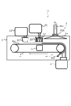
- FIG. 1 is a cross-sectional view showing a schematic configuration of a hydrogen generation device according to a first embodiment.
- FIG. 2 is a control block diagram of the hydrogen generation apparatus according to the first embodiment.
- FIG. 1 is a cross-sectional view showing a schematic configuration of a thermal inkjet head.
- FIG. 1 is a cross-sectional view showing a schematic configuration of a piezoelectric inkjet head.
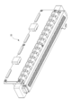
- FIG. 1 is a perspective view showing a schematic configuration of a line-type inkjet head.
- FIG. 1 is a perspective view showing a schematic configuration of a serial type inkjet head.
- FIG. 5 is a cross-sectional view showing a schematic configuration of a hydrogen generation device according to a second embodiment.
- FIG. 11 is a cross-sectional view showing a schematic configuration of a hydrogen generation device according to a third embodiment.
- a first embodiment will be described with reference to Figs. 1 to 5.
- hydrogen has been attracting attention as an alternative energy source to fossil fuels. This is because, unlike fossil fuels, hydrogen does not generate carbon dioxide, a type of greenhouse gas that leads to global warming, when burned.
- One of the systems that use hydrogen as an energy source that has been put into practical use is a fuel cell vehicle.
- a fuel cell vehicle is a vehicle that generates electricity using hydrogen as a raw material and runs by driving an electric motor with the generated electricity.
- hydrogen which is an energy source
- the hydrogen tank stores hydrogen by compressing it at a high pressure, for example, 70 MPa (700 times atmospheric pressure).
- the volumetric energy density of hydrogen is about 1/3000 of that of gasoline, so even if a 70 MPa hydrogen tank is used, only about 1/5 of the energy of gasoline can be extracted from the same volume. For this reason, fuel cell vehicles that use hydrogen tanks generally require more frequent energy refueling than cars that use gasoline.
- hydrogen carriers various substances that can transport hydrogen at a higher energy density than hydrogen tanks (i.e., hydrogen carriers) are being considered.
- hydrogen carriers ammonia and methylcyclohexane are known as hydrogen carriers, and hydrogen carriers are transported instead of hydrogen itself, and hydrogen is extracted from the hydrogen carrier when it is to be used.
- metal hydrides such as sodium borohydride are widely known, from which hydrogen can be easily extracted by pouring water on them.
- a known method of obtaining hydrogen by hydrolyzing sodium borohydride is to dissolve sodium borohydride in water and use it as an aqueous solution.
- this method has the problem that a larger amount of water is required than is theoretically necessary as indicated by the reaction formula, resulting in a decrease in the actual volumetric energy density.
- hydrogen is generated by pouring a liquid containing water onto a solid hydrogen carrier using a hydrogen generation device as described below.
- the by-products generated by the reaction between the hydrogen carrier and the liquid are collected. The by-products can be recycled into hydrogen carriers.
- the hydrogen generating device 1 of this embodiment is a device that places a solid (powder in this embodiment) hydrogen carrier on a conveyor belt 41 (on a conveying member), discharges a liquid containing water onto the hydrogen carrier, and reacts the hydrogen carrier with the liquid containing water on the conveyor belt 41 to generate hydrogen.
- the hydrogen generating device 1 mainly includes the conveyor belt 41, a powder coating device 12 as a coating device, a liquid discharge device 22 as a discharge device, a hydrogen recovery device 31, and a by-product recovery device 61.
- the conveyor belt 41 rotates in the direction of the arrow in Figure 1.
- the powder coating device 12 receives a supply of hydrogen carrier from a hydrogen carrier storage case 11 that contains powdered hydrogen carrier, and applies the hydrogen carrier to the surface 41a of the conveyor belt 41.
- the liquid ejection device 22 is disposed downstream of the powder coating device 12 in the rotation direction of the conveyor belt 41, receives a supply of liquid from a liquid storage case 21 that contains a liquid including water, and ejects the liquid onto the hydrogen carrier applied to the surface 41a of the conveyor belt 41.
- the hydrogen recovery device 31 is disposed downstream of the liquid ejection device 22 in the rotation direction of the conveyor belt 41, and recovers hydrogen generated by the reaction between the hydrogen carrier and the liquid on the surface 41a of the conveyor belt 41.
- the by-product recovery device 61 recovers by-products generated by the reaction between the hydrogen carrier and the liquid on the surface 41a of the conveyor belt 41.
- the by-products referred to here refer to products other than hydrogen that are generated by the reaction between the hydrogen carrier and the liquid.
- the hydrogen generation device 1 of this embodiment further includes a heating device 51 that heats the conveyor belt 41. The heating device 51 may be omitted.
- This hydrogen generation device 1 can carry out a series of processes, such as generating hydrogen on the conveyor belt 41 by reacting the hydrogen carrier with a liquid containing water, and collecting the by-products after the reaction. This has the advantage that hydrogen can be generated continuously and stably over the long term with a compact device configuration.
- the operation of the hydrogen generation device 1 is as follows. First, the conveyor belt 41 starts operating, and at the same time, the heating device 51 starts heating. When the conveying speed of the conveyor belt 41 stabilizes at a predetermined speed and the surface temperature of the conveyor belt 41 reaches a set temperature, the powder coating device 12 starts operating and applies the hydrogen carrier onto the conveyor belt 41. Liquid is discharged from the liquid discharge device 22 in time with the hydrogen carrier coming under the liquid discharge device 22, starting a reaction between the hydrogen carrier and the liquid, and the generated hydrogen is collected by the hydrogen recovery device 31. Note that if the hydrogen generation device 1 does not have a heating device 51, the hydrogen carrier may be applied onto the conveyor belt 41 regardless of the temperature of the conveyor belt 41.
- the "hydrogen carrier” in this embodiment is not particularly limited as long as it is a solid hydrogen carrier that generates hydrogen when a liquid containing water is poured on it.
- solid metal hydrides such as sodium borohydride, potassium borohydride, lithium borohydride, zinc borohydride, lithium aluminum hydride, sodium aluminum hydride, magnesium aluminum hydride, calcium aluminum hydride, magnesium hydride, lithium hydride, sodium hydride, and calcium hydride, and metal powders such as aluminum, zinc, calcium, and magnesium, or a mixture of multiple types thereof can be used.
- additives such as a reaction promoter and a desiccant can be included.
- Sodium borohydride is preferably used as the hydrogen carrier. This is because the ratio of hydrogen in the sodium borohydride molecule is high relative to the molecular weight of sodium borohydride, resulting in a high energy density. In addition, the hydrogen generation reaction proceeds at low temperatures close to room temperature, making it possible to obtain hydrogen efficiently, and it is less likely to ignite when it comes into contact with water, resulting in fewer safety concerns.
- the hydrogen carrier of this embodiment is preferably a solid such as a powder or granules, but can also be used in solid form such as a sheet, pellet, or paste. Powders with a particle size of about 10 ⁇ m to 10 mm can be used, with those with a particle size of about 10 ⁇ m to 3 mm and those with a particle size of about 10 ⁇ m to 100 ⁇ m being more preferable.
- a sheet or pellet it is preferable to increase the surface area and the contact area with the water-containing liquid by roughening the surface or subjecting it to a porous treatment, etc., in order to increase the reactivity with the water-containing liquid.
- sodium borohydride powder with an average particle size of 50 ⁇ m is used as the solid hydrogen carrier.
- the average particle size of the solid hydrogen carrier is not limited to this.
- the powdered sodium borohydride reacts with water to generate hydrogen.
- the reacted sodium borohydride changes into a by-product, powdered sodium metaborate. This reaction is expressed by the following chemical formula. NaBH4 (sodium borohydride) + 2H2O (water) ⁇ NaBO 2 (sodium metaborate) + 4H 2 (hydrogen) ... (1)
- This reaction (chemical formula (1)) is known to be accelerated by Raney catalysts made from metals such as nickel, cobalt, and copper, and by acidic solutions such as citric acid and acetic acid.
- liquid containing water in this embodiment is not particularly limited as long as it is a liquid that reacts with the hydrogen carrier when poured and generates hydrogen. That is, the liquid containing water may be water alone. In addition, two or more types of liquid containing water may be prepared. By preparing two or more types of liquid containing water, the rate of hydrogen generation can be adjusted.
- the water-containing liquid may contain a water-soluble organic solvent.
- a water-soluble organic solvent examples include alcohols, polyalkylene glycols, glycol ethers, nitrogen-containing compounds, and sulfur-containing compounds. Two or more selected from these may be mixed and used.
- a water-soluble organic solvent By including a water-soluble organic solvent, it is possible to adjust the surface tension and the boiling and melting points of the water-containing liquid, optimizing the reaction with the hydrogen carrier.
- Surfactants can be added to liquids that contain water. Using a surfactant can reduce the surface tension of the liquid that contains water, increasing the contact area with the hydrogen carrier and allowing for an efficient reaction.
- the aqueous liquid may contain a water-soluble acidic substance.
- the acidic substance acts as a positive catalyst in the reaction between the aqueous liquid and the hydrogen carrier.
- the speed at which hydrogen is generated can be adjusted by adjusting the amount of the aqueous liquid containing the acidic substance. In particular, the speed at which hydrogen is generated can be increased by making the pH obtained by the aqueous liquid and the hydrogen carrier less than 9.0.
- acids include, but are not limited to, various acids such as hydrochloric acid, sulfuric acid, nitric acid, boric acid, and organic acids.
- the water-containing liquid may contain a water-soluble basic substance.
- the basic substance acts as a negative catalyst in the reaction between the water-containing liquid and the hydrogen carrier.
- the speed at which hydrogen is generated can be adjusted by adjusting the amount of the liquid containing the basic substance. In particular, the speed at which hydrogen is generated can be slowed down by setting the pH obtained by the water-containing liquid and the hydrogen carrier to 9.0 or higher.
- bases include, but are not limited to, various bases such as sodium hydroxide, potassium hydroxide, and aqueous ammonia.
- the liquid containing water may contain a buffer solution.
- the buffer solution acts to suppress pH changes during the reaction between the liquid containing water and the hydrogen carrier.
- the speed at which hydrogen is generated can be adjusted by adjusting the amount of the liquid containing the buffering agent.
- buffer solutions include, but are not limited to, phosphate buffer, glycine buffer, Good's buffer, Tris buffer, and ammonia buffer.
- liquids containing water may contain various additives such as antifoaming agents, pH adjusters, viscosity adjusters, rust inhibitors, preservatives, antifungal agents, antioxidants, and anti-reducing agents, as necessary.
- the catalyst may be structured such that the catalyst material is supported on a porous material such as gamma alumina or alpha alumina, or on carbon powder. By increasing the contact area between the hydrogen carrier and the catalyst material, the hydrogen generation speed can be adjusted.
- the hydrogen carrier reacts with liquids containing water to generate hydrogen. For this reason, it may also react with water in the external environment, such as moisture in the air, generating trace amounts of hydrogen. This results in a decrease in energy density. In addition, unexpected hydrogen generation may cause safety concerns, such as deformation or damage to the device due to an increase in internal pressure in the hydrogen carrier storage case 11, or ignition due to hydrogen leaking to the outside.
- a desiccant can be used.
- the desiccant may be mixed with the hydrogen carrier.
- a bag containing a desiccant that is permeable to air and water vapor may be enclosed inside the hydrogen carrier storage case 11.
- a bag containing a desiccant may be attached to the hydrogen carrier storage case 11 so that the desiccant is not mixed with the hydrogen carrier.
- desiccants include calcium oxide (quicklime), calcium chloride, silica gel, molecular sieves, polyacrylic acid, silica alumina gel, etc., but are not limited to the substances listed above as long as they contribute to drying.
- the temperature of the water-containing liquid is preferably higher than 0° C. and lower than 80° C. If the temperature is lower than 0° C., part of the water-containing liquid will freeze, changing the concentration of the components of the water-containing liquid, and there is a possibility that the intended amount of hydrogen generation will not be obtained. On the other hand, if the temperature exceeds 80° C., evaporation of the water-containing liquid will increase, changing the concentration of the components of the water-containing liquid, and there is a possibility that the intended amount of hydrogen generation will not be obtained.
- the rate at which hydrogen is generated can be adjusted by controlling the temperature of the water-containing liquid.
- the temperature of the water-containing liquid can be measured using a contact or non-contact thermometer (not shown) installed inside or outside the liquid storage case 21 or the liquid ejection device 22.
- the temperature of the water-containing liquid can also be adjusted using a temperature adjustment device (heating device, cooling device (not shown)) inside or outside the liquid storage case 21 or the liquid ejection device 22.
- the temperature may also be adjusted by natural heat dissipation, etc.
- the hydrogen generation device 1 of this embodiment is adapted to control the amount of water-containing liquid to be applied to the hydrogen carrier.
- the amount of liquid to be applied is controlled by a central control device (described later).
- the central control device receives signals obtained from hydrogen applications such as fuel cells supplied by the hydrogen generation device 1 and from each device of the hydrogen generation device 1, and controls the amount of liquid to be applied based on a program stored in advance.
- sodium borohydride when sodium borohydride is used as a hydrogen carrier, it generates hydrogen by reacting with a liquid containing water.
- the sodium borohydride that reacts changes into sodium metaborate.
- the chemical formula for this reaction is shown above in chemical formula (1).
- Sodium metaborate is also known to exist as a hydrate, so if a liquid containing the equivalent of 2 mol or more of water is added, sodium metaborate will remain as a hydrate after the reaction.
- Sodium metaborate exists as a maximum tetrahydrate, so if a liquid containing the equivalent of 6 mol or less of water is added, sodium metaborate hydrate will remain after the reaction. If a liquid containing the equivalent of 6 mol of water is added, there will be an excess of water, and sodium metaborate tetrahydrate and water will remain after the reaction. In order to avoid excessive reduction in energy density and reduce the amount of product recovered after the reaction, it is preferable to add a liquid containing the equivalent of 2 mol or more and 6 mol or less of water.
- the conveyor belt 41 as a conveying member is an endless belt and can convey a solid hydrogen carrier.
- the conveyor belt 41 is stretched by a driving roller 42 and a driven roller 43.
- the driving roller 42 is fixed, and a force is applied to the driven roller 43 by a biasing force of a biasing spring (not shown) so as to push the conveyor belt toward the surface side, and a certain tension is applied to the conveyor belt 41 by this force.
- the driving roller 42 is connected to a driving unit 41b (see FIG. 2) such as a motor, and the driving unit 41b drives the driving roller 42 to rotate, so that the conveyor belt 41 moves around (i.e., rotates) in the clockwise direction (direction of the arrow) in FIG. 1.
- the conveyor belt 41 is supported by two rollers, but a configuration in which the conveyor belt 41 is supported by a plurality of rollers, such as three rollers, is also acceptable.
- the conveyor belt 41 has a tension surface stretched by two rollers (in this embodiment, a drive roller 42 and a driven roller 43), i.e., the above-mentioned surface 41a, which is arranged in a substantially horizontal direction.
- this surface 41a faces upward, and the powder coating device 12, liquid discharge device 22, and hydrogen recovery device 31 arranged above the conveyor belt 41 face surface 41a.
- Such a conveyor belt 41 has a mechanism that transports the hydrogen carrier applied onto the conveyor belt 41 from the powder coating device 12 downstream in the rotation direction, through the liquid discharge device 22 and the hydrogen recovery device 31 in that order. After that, it transports the by-products after the reaction further downstream, and transports them to the by-product recovery device 61.
- a heating device 51 that heats the conveyor belt 41 from its inner surface is provided on the inside of the conveyor belt 41.
- the conveyor belt 41 is preferably conductive from the viewpoint of not generating static electricity, and may be made of metal or resin. If it is made of metal, aluminum, iron, copper, Ni, stainless steel (SUS), etc. can be used. If it is made of resin, it is preferable that it is a resin with a high glass transition point from the viewpoint of heat resistance, and engineering plastics with high heat resistance and high durability such as polyimide, polyamideimide, and polyetheretherketone are preferable. In the case of a resin that does not have conductivity, it is preferable to make it conductive by adding an antistatic agent such as carbon black. In addition, the thickness of the conveyor belt 41 is preferably about 30 ⁇ m or more and 200 ⁇ m or less from the viewpoint of thermal conductivity. In this embodiment, an endless belt made of resin that is made conductive by adding carbon to polyimide is used as the conveyor belt 41.
- the conveying speed (rotation speed) of the conveyor belt 41 is a predetermined speed set for each type of hydrogen carrier and liquid, including water, used. It is also preferable that the conveying speed can be adjusted appropriately depending on the amount of hydrogen required. In this way, if the amount of hydrogen recovered by the hydrogen recovery device 31 does not reach the planned amount, the amount of hydrogen generated can be adjusted by adjusting the conveying speed appropriately according to the amount of hydrogen measured by a flow sensor 32 (see Figure 2) that measures the flow rate of hydrogen recovered by the hydrogen recovery device 31.
- the powder coating device 12 is a device that receives a supply of the hydrogen carrier from the hydrogen carrier storage case 11 and coats the hydrogen carrier on the conveyor belt 41. There is no problem with the thickness of the hydrogen carrier coated on the conveyor belt 41 being about 50 ⁇ m or more and 3 mm or less, but in order to improve reactivity with the reaction liquid containing water, it is preferable that the thickness be 50 ⁇ m or more and 500 ⁇ m or less.
- the hydrogen carrier storage case 11 which serves as a hydrogen carrier supply container, stores a hydrogen carrier (hydrogen carrier for supply) for supplying to the storage section of the powder coating device 12.
- This hydrogen carrier storage case 11 is detachable from the powder coating device 12. In other words, the hydrogen carrier storage case 11 is replaceable.
- the liquid ejection device (first liquid application device) 22 is a liquid application device that receives a supply of a water-containing liquid from a liquid storage case 21 that stores the water-containing liquid, and applies the water-containing liquid to the hydrogen carrier on the conveyor belt 41.
- the liquid ejection device 22 is capable of adjusting the amount of the water-containing liquid relative to the amount of the hydrogen carrier. It is preferable that the liquid ejection device 22 ejects the liquid onto the conveyor belt 41 without contacting the conveyor belt 41.
- the non-contact liquid discharge device 22 can be any type, such as a spray type, dispenser type, or inkjet type, as long as it can dispense liquid containing water in droplet form onto the hydrogen carrier, as described below.
- a spray type, dispenser type, or inkjet type By discharging the liquid onto the hydrogen carrier in droplet form, the contact area between the hydrogen carrier and the liquid increases, thereby increasing the reaction rate.
- a liquid containing water can be dispensed very thinly over a wide area, the generation of bubbles during hydrogen generation can be suppressed.
- the amount of water-containing liquid dispensed can be adjusted by adjusting the diameter and number of nozzles used to dispense the water-containing liquid, and the pressure applied to the liquid. If the device has an electrical control unit, the amount of water-containing liquid dispensed can be adjusted by opening and closing the flow path for the water-containing liquid. The amount of water dispensed can be controlled by information based on the amount of hydrogen generated or by external input.
- a contact type liquid application device may be used in combination with a non-contact type liquid ejection device.
- Examples of contact type liquid application devices include gravure offset rollers, bar coaters, die coaters, blade coaters, and knife coaters. With a contact type liquid application device, it is possible to adjust the amount of liquid applied by adjusting the type of roller, the contact pressure with the belt carrying the hydrogen carrier, the contact pressure between the blade and roller, etc.
- the liquid storage case 21 which serves as a liquid supply container, stores liquid including water to be supplied to the liquid ejection device 22.
- the liquid storage case 21 is detachable from the liquid ejection device 22. In other words, the liquid storage case 21 is replaceable.
- the hydrogen recovery device 31 is for collecting hydrogen generated by the reaction between the hydrogen carrier and a liquid containing water. As shown in FIG. 1, it may have a canopy structure, which is called an exhaust device, or the upper outer wall of the hydrogen generation device 1 may be sloped and have an exhaust outlet at the highest position. There is no problem as long as the structure is such that hydrogen generated inside the hydrogen generation device 1 can be collected.
- the hydrogen recovery device 31 of this embodiment is disposed above the conveyor belt 41 and has a collection section 31a that collects hydrogen generated on the conveyor belt 41 and a suction fan 31b that sucks in the hydrogen collected by the collection section 31a. The hydrogen sucked in by the suction fan 31b is supplied to a supply destination such as a fuel cell through a pipe 31c.
- Fuel cells one of the destinations for hydrogen, require dry hydrogen.
- the collected gas may contain not only hydrogen, but also water vapor and evaporated alkaline substances produced by the reaction. For this reason, it is preferable to provide a mechanism for removing substances other than hydrogen from the gas, such as a filter containing water or silica gel, or a steam trap with a cooling device, in the hydrogen flow path, such as pipe 31c.
- the by-product recovery device 61 as a solid product recovery device removes the by-products on the conveyor belt 41 from the conveyor belt 41 and sends the by-products (solid products) to a by-product recovery case 62.
- the by-product recovery device 61 includes a recovery blade 61a that contacts the conveyor belt 41 and a blade holding member (not shown) that holds the recovery blade 61a.
- the recovery blade 61a preferably contacts the outer peripheral surface of the conveyor belt 41, which is tensioned by a roller that tensions the conveyor belt 41, in this embodiment, the drive roller 42.
- the recovery blade 61a also preferably contacts a surface other than the surface 41a, such as the vertical lower surface or horizontal side surface of the conveyor belt 41.
- the by-product recovery case 62 is also preferably positioned vertically below the recovery blade 61a. This allows the by-products recovered by the recovery blade 61a to fall by gravity and be recovered by the by-product recovery case 62.
- the recovery blade 61a There are no particular restrictions on the material of the recovery blade 61a, but examples include rubber blades used for cleaning intermediate transfer belts in copiers and the like. These are made of rubber such as silicone rubber or urethane rubber and are molded into a plate shape with corners, and are attached so that the corners come into contact in the opposite direction to the direction of movement of the transport belt 41, removing by-products on the transport belt 41.
- the recovery blade 61a may also be a spatula-shaped one known as a scraper, made of metal or glass.
- the blade holding member supports the recovery blade 61a and utilizes the flexure of the blade holding member to apply a certain amount of pressure to the recovery blade 61a.
- pressure is applied, it is preferable for it to be made of metal.
- the by-product recovery case 62 which serves as a recovery container, is a case for recovering by-products recovered from the conveyor belt 41 by the recovery blade 61a.
- This by-product recovery case 62 is detachable from the by-product recovery device 61. In other words, the by-product recovery case 62 is replaceable.
- the heating device 51 heats the inner circumferential surface of the conveyor belt 41 to promote the reaction between the hydrogen carrier and the water-containing liquid and generate hydrogen stably. This makes it possible to stably extract hydrogen during the hydrolysis reaction of the hydrogen carrier without using a reaction promoter such as a catalyst.
- the method of heating the conveyor belt 41 using the heating device 51 is more energy efficient than methods such as heating the hydrogen carrier or heating a liquid containing water, because the heating range and timing can be limited to when the hydrogen carrier reacts with the liquid containing water.
- the heating device 51 may be one that heats the conveyor belt 41 via a film or belt, one that transfers the heat of a heater directly to the conveyor belt 41, or one that uses an induction heating heater if the conveyor belt 41 is made of metal. There are no particular limitations as long as it can transfer heat quickly to the conveyor belt 41 and heat it. It is also acceptable to have a heater on the outer periphery of the conveyor belt 41 and directly heat the liquid containing the hydrogen carrier and water. However, when heating from the outer periphery, hydrogen should not come into contact with the heater from a safety standpoint, so a configuration in which heating is performed via a heating film or the like is preferable.
- the central control unit 101 comprises a control unit 112, a RAM (Random Access Memory) 111, a storage 113 for storing programs, a communication interface, a signal transmission unit 114, and a signal reception unit 115.
- the control unit 112 comprises a CPU (Central Processing Unit) or a CPU plus a ROM (Read Only Memory), and issues control commands to the entire hydrogen generation apparatus 1 by executing a program stored in the storage 113.
- RAM 111 is the main working memory for control unit 112.
- Storage 113 is a memory area for storing control programs and the like, and control unit 112 performs processing by reading out control programs, temporarily stored time-series data, log information, and the like from RAM 111 and storage 113.
- the control unit 112 receives information from an external application 102, such as a hydrogen application, such as a fuel cell supplied by the hydrogen generation device 1, or a fuel cell application, such as an FCV (Fuel Cell Vehicle) that uses a fuel cell.
- the control unit 112 also receives information from the engine unit 103 of the hydrogen generation device 1 via the signal receiving unit 115.
- Information from the engine unit 103 includes the amount of hydrogen detected by the flow sensor 32 provided in the hydrogen recovery device 31, and information from the remaining amount detection sensors 11a, 12a, and 22a provided in the hydrogen carrier storage case 11, powder coating device 12, and liquid discharge device 22.
- the remaining amount detection sensor 11a is provided in the hydrogen carrier storage case 11 and is a sensor that detects the remaining amount of hydrogen carrier in the hydrogen carrier storage case 11.
- the remaining amount detection sensor 12a is provided in the powder coating device 12 and is a sensor that detects the remaining amount of hydrogen carrier in the powder coating device 12.
- the remaining amount detection sensor 22a is provided in the liquid ejection device 22 and is a sensor that detects the remaining amount of liquid, including water, in the liquid ejection device 22.
- control unit 112 transmits, via the signal transmission unit 114, a supply signal to the hydrogen carrier storage case 11, a drive signal for the powder coating device 12 and the liquid ejection device 22, a drive signal for the conveyor belt 41, and the like, as signals generated based on pre-programmed control information.
- the hydrogen carrier storage case 11 has a drive unit 11b for supplying the hydrogen carrier to the powder coating device 12.
- the powder coating device 12 has a drive unit 12b for coating the hydrogen carrier onto the conveyor belt 41.
- the liquid ejection device 22 has a drive unit 22b for ejecting liquid onto the hydrogen carrier on the conveyor belt 41.
- the conveyor belt 41 is driven by the drive unit 41b as described above.
- the control unit 112 controls the driving of these drive units 11b, 12b, 22b, 41b.
- the drive unit 11b of the hydrogen carrier storage case 11 is, for example, a motor or solenoid that drives a shutter provided at the connection between the hydrogen carrier storage case 11 and the powder coating device 12.
- the control unit 112 starts and stops the supply of hydrogen carrier from the hydrogen carrier storage case 11 to the powder coating device 12, for example, by driving the drive unit 11b to open and close the shutter.
- the driving unit 12b of the powder coating device 12 is, for example, a motor that drives a roller for coating the hydrogen carrier onto the conveyor belt 41.
- the control unit 112 drives the driving unit 12b to control the driving of the roller, thereby starting and stopping the application of the hydrogen carrier from the powder coating device 12 to the surface 41a of the conveyor belt 41.
- the drive unit 22b of the liquid ejection device 22 is for ejecting liquid onto the conveyor belt 41, for example, and the drive configuration differs depending on the method.
- the control unit 112 controls the drive of the drive unit 22b, thereby starting and stopping the ejection of liquid from the liquid ejection device 22 onto the surface 41a of the conveyor belt 41.
- the control unit 112 also controls the amount of liquid that the liquid ejection device 22 applies to the hydrogen carrier.
- the drive unit 41b of the conveyor belt 41 is, for example, a motor.
- the control unit 112 controls the drive of the drive unit 41b to drive and stop the conveyor belt 41, and further to control the drive speed.
- liquid discharge device 22 As a method for producing hydrogen, sodium borohydride may be dissolved in water and used. However, in this method, a larger amount of water is required than the amount of water theoretically indicated by the reaction formula, and this causes a problem of a decrease in the actual volumetric energy density. In addition, it is unavoidable that hydrogen is generated little by little during storage as an aqueous solution, which also reduces the volumetric energy density. For this reason, a hydrogen generating device capable of generating hydrogen while suppressing the decrease in volumetric energy density is desired.
- the liquid ejection device 22 ejects liquid containing water in the form of droplets.
- the liquid ejection device 22 uses an inkjet system used in inkjet printers and the like. Note that, although an inkjet head is used as the liquid ejection device 22 below, this includes those having a similar configuration even if they are not actually used in inkjet heads. In other words, the inkjet heads described below also include those having a similar configuration even if they are not necessarily manufactured for inkjet printers.
- the liquid ejection device 22 By using an inkjet head as the liquid ejection device 22, it is possible to apply the water-containing liquid to the hydrogen carrier in the form of tiny droplets. As a result, when applying the same amount of liquid, the contact area between the hydrogen carrier and the water-containing liquid is increased compared to other methods, which makes it possible to increase the reaction rate and generate hydrogen while suppressing a decrease in volumetric energy density. In addition, by ejecting the water-containing liquid in the form of droplets, the amount of the water-containing liquid can be controlled very accurately, making it possible to generate only the required amount of hydrogen when it is required.
- the water-containing liquid in droplet form, it is possible to apply a very thin layer of water-containing liquid over a wide area, which helps to suppress the generation of bubbles when hydrogen is generated. If bubbles are generated, they may reach the hydrogen recovery path, causing contamination, i.e., impurities may be mixed into the recovered hydrogen. The bubbles may also block the hydrogen outlet. Furthermore, if the device is filled with bubbles, the bubbles will adhere to the device. If the bubbles adhere to the device, for example, they may interfere with the application of the hydrogen carrier or the discharge of the water-containing liquid in the next process of generating hydrogen.
- the inkjet head can be equipped with two or more types of water-containing liquid.
- the water-containing liquid can be supplied to the inkjet head from a liquid storage section (not shown) provided in the hydrogen generation device 1 via a tube or the like.
- the ratio and amount of the two or more types of liquid applied can be accurately controlled. This allows the total composition of the water-containing liquid applied to the hydrogen carrier to be changed, which can promote or suppress hydrogen generation.
- the inkjet head can be either a thermal type head or a piezoelectric type head.
- a thermal type head 220 has a heater 222 disposed in a flow path 221 filled with a liquid including water, and ejects liquid 224 by generating bubbles 223 due to heating by the heater 222. That is, the thermal type head 220 has a heater (heat transfer element) 222 mounted on a recording element substrate as an ejection element for ejecting liquid. Then, bubbles 223 are generated by heating the heater 222, and liquid 224 is ejected from a nozzle 225.
- the piezoelectric head 220A has a piezoelectric element 222A disposed in a flow path 221A filled with a liquid including water, and ejects liquid 224 by applying a voltage to the piezoelectric element 222A. That is, the piezoelectric head 220A has a piezoelectric element (piezoelectric element) 222A mounted on a recording element substrate as an ejection element for ejecting liquid, and generates pressure by vibration of the piezoelectric element 222A, ejecting liquid 224 from nozzle 225A, as shown exaggeratedly by the solid and dashed lines in Figure 3B.
- Both types of heads have nozzles 225, 225A that eject liquid in droplets. Therefore, as described above, the contact area between the hydrogen carrier and the water-containing liquid can be increased to increase the reaction rate, making it possible to generate hydrogen while suppressing a decrease in volumetric energy density.
- the actuator part of the thermal type head is small, making it possible to miniaturize the device.
- the piezoelectric type head can control the size of the droplets of the water-containing liquid by controlling the displacement amount of the actuator part, making it possible to change the rate at which hydrogen is generated.
- the inkjet head can be either a line type inkjet head 23 shown in FIG. 4 or a serial type inkjet head 24 shown in FIG. 5.
- the line type inkjet head 23 has a housing unit 23a equipped with a plurality of recording element substrates for ejecting liquid, and ejects liquid across the entire width of the target without moving.
- the serial type inkjet head 24 has a housing unit 24a equipped with a recording element substrate for ejecting liquid mounted on a carriage (not shown), and ejects liquid while scanning the target in the width direction.
- the "width direction" is the width direction of the conveyor belt 41 that intersects with the rotation direction of the conveyor belt 41 (orthogonal in this embodiment).
- the line-type inkjet head 23 has a supply path that supplies the water-containing liquid to the line-type inkjet head 23, which is connected to the liquid storage case 21 in FIG. 1.
- the line-type inkjet head 23 can dispense only one type of water-containing liquid.
- a partition is provided in the liquid storage case 21 to prevent the multiple types of water-containing liquid from mixing, and multiple liquid supply paths to the line-type inkjet head 23 can also be provided to prevent the water-containing liquid from mixing. If a flow path is provided in the nozzle of the line-type inkjet head 23 so that the liquids do not mix, it is possible to dispense multiple types of water-containing liquid in any amount.
- multiple liquid storage cases 21 and multiple line-type inkjet heads 23 can be provided to dispense multiple types of water-containing liquid in any amount.
- the line-type inkjet head 23 is also electrically connected to an electrical control unit that transmits power and ejection control signals.
- the electrical signal path to the line-type inkjet head 23 is the same as the electrical signal path to the liquid ejection device 22 shown in FIG. 2.
- the serial type inkjet head 24 has a supply path that supplies the water-containing liquid to the serial type inkjet head 24, which is connected to the liquid storage case 21 in FIG. 1.
- the serial type inkjet head 24 is also capable of depositing only one type of water-containing liquid.
- a partition is provided in the liquid storage case 21 to prevent the multiple types of water-containing liquid from mixing, and multiple liquid supply paths to the serial type inkjet head 24 are also provided to prevent the water-containing liquids from mixing. If a flow path is provided in the nozzle in the serial type inkjet head 24 so that the liquids do not mix, it is also possible to deposit multiple types of water-containing liquid in any amount.
- the serial type inkjet head 24 uses the so-called ink tank used in inkjet printers as the liquid storage case 21, and can dispense liquids containing multiple types of water by filling multiple ink tanks.
- the serial inkjet head 24 is also electrically connected to an electrical control unit that transmits power and ejection control signals.
- the electrical signal path to the serial inkjet head 24 is the same as the electrical signal path to the liquid ejection device shown in FIG. 2.
- the liquid ejection device 22 preferably ejects the water-containing liquid in droplet form onto the hydrogen carrier with a volume of 100 pl (picoliters) or less.
- the liquid ejected by the liquid ejection device 22 is preferably 20 pl or less.
- the contact area between the hydrogen carrier and the water-containing liquid increases, thereby increasing the reaction rate.
- the water-containing liquid can be applied very thinly over a wide area, which suppresses the generation of bubbles when hydrogen is generated.
- the liquid discharge device 22 described above provides 2 mols of water for every 1 mol of sodium borohydride, allowing the sodium borohydride to react without excess or deficiency, making it possible to recover hydrogen most efficiently. Therefore, it is desirable for the molar ratio of the amount of water provided by the liquid discharge device 22 to sodium borohydride to be approximately 1:2.
- the amount of sodium borohydride can be changed by the supply amount from the powder coating device 12 and the conveying speed of the conveyor belt 41.
- the amount of sodium borohydride that reaches the liquid ejection device 22 is calculated from the supply amount and conveying speed, and the amount of liquid containing water is controlled.
- the liquid applied to the sodium borohydride from the dispenser is not limited to water (pure water), but may be an aqueous solution in which a water-soluble acidic substance or a water-soluble basic substance is dissolved, an aqueous solution in which a water-soluble organic solvent is dissolved, or a buffer solution that stabilizes the pH at a constant value.
- the liquid containing water is ejected in droplets onto the hydrogen carrier by the liquid ejection device 22, which increases the contact area between the hydrogen carrier and the liquid containing water, thereby increasing the reaction rate and making it easier to promote the reaction between the hydrogen carrier and the liquid containing water on the conveyor belt 41.
- the liquid applied to the sodium borohydride from the liquid discharge device 22 is not limited to water (pure water), but may be an aqueous solution containing a water-soluble acidic substance or a water-soluble basic substance, or may be an aqueous solution containing a water-soluble organic solvent. It may also be a buffer solution that stabilizes the pH at a constant value.
- an inkjet head is used as the liquid ejection device 22, but other configurations such as a dispenser may also be used.
- the hydrogen generating device 1A of this embodiment differs from the first embodiment in that, in addition to the liquid ejection device (first liquid application device) 22, a liquid application device (second liquid application device) 26 capable of supplying a liquid containing water to the conveyor belt 41 is installed upstream of the powder coating device 12 with respect to the rotation direction of the conveyor belt 41. Since the other configurations and functions are the same as those of the first embodiment described above, the same reference numerals are used for the similar configurations, and the description and illustration are omitted or simplified, and the following description will focus on the points that are different from the first embodiment.
- the liquid application device 26 uses a gravure offset roller.
- a gravure offset roller is a rubber roller used in offset printing and gravure printing.
- the liquid application device 26 is installed upstream of the powder coating device 12 in the rotation direction of the conveyor belt 41.
- the liquid application device 26 is positioned so as to supply a liquid containing water to the portion of the outer circumferential surface of the conveyor belt 41 that is stretched over the driven roller 43.
- the control unit 112 controls the amount of liquid that the liquid application device 26 applies to the hydrogen carrier.
- the amount of liquid containing water is the sum of the amount applied by the liquid application device 26 and the amount applied by the liquid ejection device 22.
- the molar ratio of the amount of water applied to sodium borohydride is about 1:2.
- the liquid applied to sodium borohydride from the liquid ejection device 22 and the liquid application device 26 is not limited to water (pure water), but may be an aqueous solution in which a water-soluble acidic substance or a water-soluble basic substance is dissolved, or may be an aqueous solution in which a water-soluble organic solvent is dissolved. It may also be a buffer solution that stabilizes the pH at a certain value.
- the third embodiment will be described with reference to Fig. 7.
- the hydrogen generating device 1B of this embodiment differs from the first embodiment in that a temperature adjustment device 25 is provided in the liquid discharge device 22. Since the other configurations and functions are the same as those of the first embodiment described above, the same reference numerals are used for the similar configurations, and the description and illustrations are omitted or simplified. The following description will focus on the points that are different from the first embodiment.
- a temperature adjustment device 25 is installed outside the liquid ejection device 22.
- the temperature adjustment device 25 is a ceramic heater.
- a thermometer is provided inside the temperature adjustment device 25.
- the control unit 112 controls the temperature adjustment device 25 based on the detection signal of the thermometer to adjust the temperature of the liquid inside the liquid ejection device 22 to a predetermined temperature range.
- the predetermined temperature range is a range higher than 0°C and lower than 80°C.
- the temperature adjustment device 25 may be a combination of a heater and a cooler, and the temperature of the liquid inside the liquid ejection device 22 may be adjusted to a predetermined temperature range by PID control of these.
- the temperature adjustment device 25 may also be installed inside the liquid ejection device 22.
- the temperature adjustment device 25 may be installed inside or outside the liquid storage case 21.
- a thermometer for temperature adjustment may be installed inside or outside the liquid ejection device 22.
- the liquid inside the liquid discharge device 22 is adjusted to a predetermined temperature range by the temperature adjustment device 25, so that it is possible to apply a heated liquid containing water to the hydrogen carrier.
- This increases the reaction rate between the hydrogen carrier and the liquid containing water, allowing hydrogen generation to occur quickly. This means that hydrogen can be obtained quickly when needed.
- the reaction between sodium borohydride and water is an exothermic reaction, the conveyor belt 41 in the hydrogen generation device 1 is heated when hydrogen is generated. At this time, the desired hydrogen generation rate can be obtained by controlling the temperature of the liquid containing water.
- the liquid ejection device 22 is capable of ejecting liquid containing two or more types of water with different pH values. Since the other configurations and functions are the same as those of the first embodiment described above, the same reference numerals are used for the similar configurations, and the description and illustrations are omitted or simplified. The following description will focus on the points that are different from the first embodiment.
- the reaction was mainly controlled by the amount of liquid applied to the hydrogen carrier.
- hydrogen can be obtained at a desired reaction speed by changing the pH of the applied liquid.
- a partition is provided in the liquid storage case 21 to prevent the two types of water-containing liquid from mixing, and the water used in the first embodiment and a 30% aqueous solution of citric acid are placed in the liquid storage case 21 without mixing.
- liquid supply paths are provided from the liquid storage case 21 to the serial type inkjet head 24, and a flow path is provided that prevents the liquids from mixing even in the nozzles of the serial type inkjet head 24. This makes it possible to dispense two types of liquid in any desired amount.
- the reaction rate with the hydrogen carrier can be increased, allowing hydrogen generation to occur quickly.
- the desired hydrogen generation rate can be obtained by controlling the ratio of the water-containing liquid and the citric acid aqueous solution applied.
- the two types of liquid, water and the citric acid aqueous solution can be applied at will by either applying only water, applying water and the citric acid aqueous solution, or applying only the citric acid aqueous solution.
- a 5% aqueous solution of sodium hydroxide may be prepared and applied.
- the reaction rate with the hydrogen carrier can be reduced, and the hydrogen generation rate can be slowed or stopped. This allows the desired hydrogen generation rate to be obtained.
- the three types of liquids, water, citric acid solution, and sodium hydroxide solution can be applied arbitrarily by applying only water, applying water and citric acid solution, applying only citric acid solution, applying water + sodium hydroxide solution, or applying only sodium hydroxide solution.
- 100 mM phosphate buffer with a pH of 6.5 can be used instead of water.
- the pH of the water may change due to external environmental factors such as carbon dioxide concentration, but by using a buffer solution and stabilizing the pH, the desired hydrogen generation rate can be obtained.
- the hydrogen generating device according to the present invention is suitable as a hydrogen generating device that generates hydrogen using a hydrogen carrier as a raw material, which has the property of generating hydrogen when a liquid containing water is poured on it.
Landscapes
- Chemical & Material Sciences (AREA)
- Chemical Kinetics & Catalysis (AREA)
- Engineering & Computer Science (AREA)
- Organic Chemistry (AREA)
- Sustainable Development (AREA)
- General Chemical & Material Sciences (AREA)
- Electrochemistry (AREA)
- Sustainable Energy (AREA)
- Life Sciences & Earth Sciences (AREA)
- Manufacturing & Machinery (AREA)
- General Health & Medical Sciences (AREA)
- Inorganic Chemistry (AREA)
- Combustion & Propulsion (AREA)
- Health & Medical Sciences (AREA)
- Fuel Cell (AREA)
Priority Applications (2)
| Application Number | Priority Date | Filing Date | Title |
|---|---|---|---|
| CN202380086649.7A CN120379928A (zh) | 2022-12-20 | 2023-12-13 | 氢产生装置 |
| US19/240,748 US20250304439A1 (en) | 2022-12-20 | 2025-06-17 | Hydrogen generation apparatus |
Applications Claiming Priority (2)
| Application Number | Priority Date | Filing Date | Title |
|---|---|---|---|
| JP2022-203052 | 2022-12-20 | ||
| JP2022203052A JP2024088072A (ja) | 2022-12-20 | 2022-12-20 | 水素発生装置 |
Related Child Applications (1)
| Application Number | Title | Priority Date | Filing Date |
|---|---|---|---|
| US19/240,748 Continuation US20250304439A1 (en) | 2022-12-20 | 2025-06-17 | Hydrogen generation apparatus |
Publications (1)
| Publication Number | Publication Date |
|---|---|
| WO2024135482A1 true WO2024135482A1 (ja) | 2024-06-27 |
Family
ID=91588801
Family Applications (1)
| Application Number | Title | Priority Date | Filing Date |
|---|---|---|---|
| PCT/JP2023/044543 Ceased WO2024135482A1 (ja) | 2022-12-20 | 2023-12-13 | 水素発生装置 |
Country Status (4)
| Country | Link |
|---|---|
| US (1) | US20250304439A1 (enExample) |
| JP (1) | JP2024088072A (enExample) |
| CN (1) | CN120379928A (enExample) |
| WO (1) | WO2024135482A1 (enExample) |
Citations (5)
| Publication number | Priority date | Publication date | Assignee | Title |
|---|---|---|---|---|
| JP2004002189A (ja) * | 2002-05-28 | 2004-01-08 | Hewlett-Packard Development Co Lp | 水素発生システム |
| JP2009208972A (ja) * | 2008-02-29 | 2009-09-17 | Mitsubishi Heavy Ind Ltd | 水素発生装置 |
| JP2017114708A (ja) * | 2015-12-22 | 2017-06-29 | 株式会社 ハイドリック・パワーシステムズ | 水素発生装置、水素発生システム及び燃料電池システム |
| JP2020517577A (ja) * | 2017-04-22 | 2020-06-18 | ハイドロジェン テック センディリアン ベルハッド | 水素ガス生成装置 |
| JP2023161453A (ja) * | 2022-04-25 | 2023-11-07 | 日本軽金属株式会社 | 水素発生装置及び水素発生システム |
-
2022
- 2022-12-20 JP JP2022203052A patent/JP2024088072A/ja active Pending
-
2023
- 2023-12-13 WO PCT/JP2023/044543 patent/WO2024135482A1/ja not_active Ceased
- 2023-12-13 CN CN202380086649.7A patent/CN120379928A/zh active Pending
-
2025
- 2025-06-17 US US19/240,748 patent/US20250304439A1/en active Pending
Patent Citations (5)
| Publication number | Priority date | Publication date | Assignee | Title |
|---|---|---|---|---|
| JP2004002189A (ja) * | 2002-05-28 | 2004-01-08 | Hewlett-Packard Development Co Lp | 水素発生システム |
| JP2009208972A (ja) * | 2008-02-29 | 2009-09-17 | Mitsubishi Heavy Ind Ltd | 水素発生装置 |
| JP2017114708A (ja) * | 2015-12-22 | 2017-06-29 | 株式会社 ハイドリック・パワーシステムズ | 水素発生装置、水素発生システム及び燃料電池システム |
| JP2020517577A (ja) * | 2017-04-22 | 2020-06-18 | ハイドロジェン テック センディリアン ベルハッド | 水素ガス生成装置 |
| JP2023161453A (ja) * | 2022-04-25 | 2023-11-07 | 日本軽金属株式会社 | 水素発生装置及び水素発生システム |
Also Published As
| Publication number | Publication date |
|---|---|
| US20250304439A1 (en) | 2025-10-02 |
| JP2024088072A (ja) | 2024-07-02 |
| CN120379928A (zh) | 2025-07-25 |
Similar Documents
| Publication | Publication Date | Title |
|---|---|---|
| CN1313358C (zh) | 用于处理从氢发生器排出的燃料溶液的方法和装置 | |
| US9669371B2 (en) | Hydrogen generation systems utilizing sodium silicide and sodium silica gel materials | |
| US9156687B2 (en) | Water reactive hydrogen generation system and method with separation of waste products from water reactive materials | |
| EP3442902B1 (en) | Pem fuel cell power systems with efficient hydrogen generation | |
| JP2004002189A (ja) | 水素発生システム | |
| KR101008427B1 (ko) | 연료전지 시스템 | |
| CN100481598C (zh) | 燃料盒及燃料电池系统 | |
| WO2024135482A1 (ja) | 水素発生装置 | |
| WO2024135480A1 (ja) | 水素発生装置 | |
| WO2024135481A1 (ja) | 水素発生装置 | |
| US20070081939A1 (en) | Solid fuel packaging system and method or hydrogen generation | |
| JP5135580B2 (ja) | 水素発生装置及び燃料電池システム | |
| KR20140132346A (ko) | 규소 나트륨 및 실리카 겔 나트륨 재료를 이용하는 수소 발생 시스템 및 방법 | |
| US20250312758A1 (en) | Hydrogen generation apparatus | |
| US20070084115A1 (en) | Solid fuel packaging system and method of hydrogen generation | |
| CN110466256A (zh) | 液体喷射装置以及液体喷射装置的动作方法 | |
| WO2024135478A1 (ja) | 水素発生装置及び反応ケース | |
| JP2004181844A (ja) | インクジェット記録装置 | |
| JP2008181859A (ja) | 固体高分子形燃料電池の電極の製造装置及びこれを利用する製造方法 | |
| JP2004303594A (ja) | 燃料電池、その製造方法、電子機器および自動車 | |
| US20050008932A1 (en) | Fluid supply device for electrochemical cell | |
| JP5955509B2 (ja) | 電解質膜の製造方法、電解質膜の製造装置 |
Legal Events
| Date | Code | Title | Description |
|---|---|---|---|
| 121 | Ep: the epo has been informed by wipo that ep was designated in this application |
Ref document number: 23906847 Country of ref document: EP Kind code of ref document: A1 |
|
| WWE | Wipo information: entry into national phase |
Ref document number: 202380086649.7 Country of ref document: CN |
|
| NENP | Non-entry into the national phase |
Ref country code: DE |
|
| WWP | Wipo information: published in national office |
Ref document number: 202380086649.7 Country of ref document: CN |
|
| 122 | Ep: pct application non-entry in european phase |
Ref document number: 23906847 Country of ref document: EP Kind code of ref document: A1 |