WO2024135151A1 - 基板処理方法 - Google Patents
基板処理方法 Download PDFInfo
- Publication number
- WO2024135151A1 WO2024135151A1 PCT/JP2023/040526 JP2023040526W WO2024135151A1 WO 2024135151 A1 WO2024135151 A1 WO 2024135151A1 JP 2023040526 W JP2023040526 W JP 2023040526W WO 2024135151 A1 WO2024135151 A1 WO 2024135151A1
- Authority
- WO
- WIPO (PCT)
- Prior art keywords
- substrate
- liquid
- main surface
- chemical
- nozzle
- Prior art date
- Legal status (The legal status is an assumption and is not a legal conclusion. Google has not performed a legal analysis and makes no representation as to the accuracy of the status listed.)
- Ceased
Links
Images







Classifications
-
- H—ELECTRICITY
- H10—SEMICONDUCTOR DEVICES; ELECTRIC SOLID-STATE DEVICES NOT OTHERWISE PROVIDED FOR
- H10P—GENERIC PROCESSES OR APPARATUS FOR THE MANUFACTURE OR TREATMENT OF DEVICES COVERED BY CLASS H10
- H10P70/00—Cleaning of wafers, substrates or parts of devices
- H10P70/20—Cleaning during device manufacture
-
- H—ELECTRICITY
- H10—SEMICONDUCTOR DEVICES; ELECTRIC SOLID-STATE DEVICES NOT OTHERWISE PROVIDED FOR
- H10P—GENERIC PROCESSES OR APPARATUS FOR THE MANUFACTURE OR TREATMENT OF DEVICES COVERED BY CLASS H10
- H10P52/00—Grinding, lapping or polishing of wafers, substrates or parts of devices
-
- H—ELECTRICITY
- H10—SEMICONDUCTOR DEVICES; ELECTRIC SOLID-STATE DEVICES NOT OTHERWISE PROVIDED FOR
- H10P—GENERIC PROCESSES OR APPARATUS FOR THE MANUFACTURE OR TREATMENT OF DEVICES COVERED BY CLASS H10
- H10P72/00—Handling or holding of wafers, substrates or devices during manufacture or treatment thereof
- H10P72/04—Apparatus for manufacture or treatment
- H10P72/0402—Apparatus for fluid treatment
- H10P72/0406—Apparatus for fluid treatment for cleaning followed by drying, rinsing, stripping, blasting or the like
- H10P72/0411—Apparatus for fluid treatment for cleaning followed by drying, rinsing, stripping, blasting or the like for wet cleaning or washing
- H10P72/0414—Apparatus for fluid treatment for cleaning followed by drying, rinsing, stripping, blasting or the like for wet cleaning or washing using mainly spraying means, e.g. nozzles
Definitions
- This disclosure relates to a substrate processing method.
- the substrate processing apparatus includes a spin chuck, a first chemical liquid nozzle, a second chemical liquid nozzle, and a rinse liquid nozzle.
- the spin chuck holds the substrate in a horizontal position and rotates the substrate around a vertical rotation axis that passes through the center of the substrate.
- the first chemical liquid nozzle is a shower nozzle.
- the first chemical liquid nozzle and the second chemical liquid nozzle eject chemical liquid in parallel toward the top surface of the rotating substrate.
- the chemical liquid spreads over the top surface of the substrate, so that the chemical liquid acts on the entire top surface of the substrate.
- the rinse liquid nozzle ejects rinse liquid toward the top surface of the rotating substrate.
- the chemical liquid on the top surface of the substrate is washed away by the rinse liquid.
- a substrate may be processed that includes a support substrate and a number of dies attached to the main surface of the support substrate. Because the thickness of the dies is greater than the thickness of the pattern, relatively deep irregularities are formed on the main surface of the substrate. For this reason, when a chemical solution is discharged toward the main surface of the substrate, the irregularities can cause the liquid to splash, and the flow of the chemical solution on the main surface of the substrate can become uneven due to the irregularities. These factors result in some positions on the main surface of the substrate where the chemical solution arrives relatively quickly and other positions where the chemical solution arrives relatively slowly. In other words, the chemical solution begins to act at different start times at each position on the main surface of the substrate. This leads to a decrease in the uniformity of the processing of the substrate.
- the present disclosure therefore aims to provide a technology that can cause the chemical solution to act more uniformly on the main surface of the substrate.
- the first aspect is a substrate processing method comprising a holding step of holding a substrate having a plurality of dies on a main surface thereof, a pre-wetting step of supplying the rinse liquid to the main surface of the substrate while rotating the substrate at a rotation speed at which the rinse liquid covers the plurality of dies, and a chemical processing step of supplying the chemical liquid from a first nozzle toward the main surface of the substrate after the pre-wetting step while rotating the substrate at a rotation speed at which the chemical liquid covers the plurality of dies.
- the second aspect is a substrate processing method according to the first aspect, in which the holding step holds the substrate in a position in which the main surface faces upward, the pre-wetting step is a pre-puddle step that maintains a liquid film of the rinse liquid covering the multiple dies on the main surface of the substrate, and the chemical processing step is a chemical puddle step that maintains a liquid film of the chemical liquid covering the multiple dies on the main surface of the substrate.
- the third aspect is a substrate processing method according to the second aspect, in which, in the chemical puddle step, the first nozzle having a plurality of outlets is moved back and forth in a direction along the main surface of the substrate, while the chemical liquid is discharged from the plurality of outlets toward the main surface of the substrate.
- the fourth aspect is a substrate processing method according to the second or third aspect, in which, in the chemical liquid puddle step, even after the rinsing liquid on the main surface of the substrate is replaced with the chemical liquid, the chemical liquid continues to be ejected from the first nozzle for an actual processing time longer than a replacement time required to replace the rinsing liquid with the chemical liquid.
- the fifth aspect is a substrate processing method according to any one of the second to fourth aspects, in which the difference between the chemical processing time during which the chemical is discharged from the first nozzle toward the main surface of the substrate and an integer multiple of the unit time required for one rotation of the substrate is equal to or less than one-fourth of the unit time.
- the sixth aspect is a substrate processing method according to any one of the second to fifth aspects, in which, in the pre-puddle step, the rinse liquid is ejected from the first nozzle toward the main surface of the substrate.
- the seventh aspect is a substrate processing method according to any one of the second to sixth aspects, further comprising a post-puddle step of ejecting the rinse liquid from the first nozzle toward the main surface of the substrate after the chemical puddle step, while rotating the substrate at a rotation speed at which the rinse liquid covers the multiple dies.
- the eighth aspect is a substrate processing method according to the seventh aspect, in which the difference between the rotation speed of the substrate in the chemical puddle step and the rotation speed of the substrate in the post-puddle step is 50% or less of the rotation speed of the substrate in the chemical puddle step.
- the ninth aspect is a substrate processing method according to the seventh or eighth aspect, further comprising, after the post-puddle step, a replacement promotion step of supplying the rinse liquid to the main surface of the substrate while rotating the substrate at a rotation speed higher than the rotation speed of the substrate in the post-puddle step.
- the tenth aspect is a substrate processing method according to the ninth aspect, in which, in the replacement promotion step, the rinse liquid is ejected from a second nozzle toward the center of the main surface of the substrate.
- An eleventh aspect is a substrate processing method according to the ninth or tenth aspect, further comprising, after the replacement promotion step, a drying step of drying the substrate by rotating the substrate at a rotation speed higher than the rotation speed of the substrate in the replacement promotion step.
- the twelfth aspect is a substrate processing method according to any one of the ninth to eleventh aspects, in which a set of the pre-puddle step, the chemical puddle step, the post-puddle step, and the replacement promotion step is performed multiple times, and in the chemical puddle step, different chemicals are supplied to the main surface of the substrate.
- the thirteenth aspect is a substrate processing method according to the first aspect, in which the substrate is held in the holding step with the main surface facing downward.
- a fourteenth aspect is the substrate processing method described in the thirteenth aspect, in which, in the chemical processing step, the chemical is discharged from a plurality of outlets of a first nozzle toward the main surface of the substrate, and the first nozzle discharges the chemical toward a radially outer peripheral region of the main surface at a flow rate greater than the flow rate toward a radially inner central region of the main surface of the substrate.
- the fifteenth aspect is a substrate processing method according to the first aspect, in which, in the pre-wet step, the rinsing liquid is filled into the space between the main surface of the substrate and an opposing surface of a blocking plate that faces the main surface, and, in the chemical processing step, the chemical liquid is filled into the space between the opposing surface and the main surface.
- the chemical liquid adheres to the rinsing liquid covering the multiple dies.
- the chemical liquid diffuses together with the rinsing liquid and is therefore likely to spread across the main surface of the substrate. This allows the chemical liquid to begin to act more uniformly on the main surface of the substrate. This allows the chemical treatment to be performed more uniformly on the main surface of the substrate.
- the main surface of the substrate since multiple dies are present on the main surface of the substrate, the main surface of the substrate has an uneven shape.
- the rinse liquid splashes at the corners of the dies.
- the thickness of the rinse liquid film on the main surface of the substrate decreases, and as a result, at least a portion of the surfaces of the multiple dies may be exposed and not covered by the rinse liquid.
- the substrate rotates at a rotation speed at which the rinse liquid covers the multiple dies. Therefore, the rotation speed is relatively low, and splashing of the rinse liquid can be suppressed.
- the chemical liquid adheres to the rinsing liquid covering the multiple dies.
- the chemical liquid diffuses together with the rinsing liquid, and so it is likely to spread over the main surface of the substrate.
- the chemical liquid begins to act more uniformly on the main surface of the substrate. This allows the chemical treatment to be performed more uniformly on the main surface of the substrate.
- the chemical solution can be supplied more uniformly to the main surface of the substrate.
- the fourth aspect even after the rinse liquid on the main surface of the substrate has been replaced with the chemical liquid, new chemical liquid that has not yet reacted with the main surface of the substrate continues to be ejected from the first nozzle toward the main surface of the substrate.
- the old chemical liquid that has reacted with the main surface of the substrate is pushed away by the new chemical liquid and flows down from the edge of the substrate, and the new chemical liquid acts on the main surface of the substrate. Therefore, the main surface of the substrate can be processed with a higher throughput.
- the main surface of the substrate can be processed more uniformly.
- the pre-puddle process uses the same first nozzle as the chemical puddle process, making the process simple.
- the rinse liquid is ejected from the same first nozzle as in the chemical liquid puddle process. This reduces the variation in the effective processing time from when the chemical liquid starts to be supplied until the rinse liquid is supplied at each position on the main surface of the substrate. This allows the substrate to be processed more uniformly.
- the variation in the actual processing time can be further reduced.
- the chemical liquid remaining on the main surface of the substrate can be dispersed outward from the periphery of the substrate even by the post-puddle process.
- the chemical liquid can be more reliably replaced with the rinse liquid.
- the rinsing liquid flows from the center of the substrate toward the periphery, making it easier to push the chemical liquid toward the periphery and more reliably replacing the chemical liquid with the rinsing liquid.
- the substrate is rotated at a higher rotation speed than the rotation speed in the replacement promotion step, so that the substrate can be dried more quickly.
- the rotation speed of the substrate W in the replacement promotion step is lower than the rotation speed of the substrate W in the drying step, so that splashing of the rinse liquid can be suppressed in the replacement promotion step.
- the rotation speed of the substrate is relatively high in the replacement promotion step, at least a portion of the surfaces of the multiple dies can be exposed and not covered by the rinsing liquid.
- the pre-puddle step is performed again after the replacement promotion step, a film of the rinsing liquid covers the multiple dies at the time the chemical puddle step is started. Therefore, the chemical can start to act more uniformly on the main surface of the substrate in each chemical puddle step.
- droplets of the processing liquid that are bounced off the die on the main surface of the substrate flow downward. This prevents the processing liquid from scattering around.
- the chemical solution can be supplied more uniformly to the main surface of the substrate.
- the chemical solution is supplied while the space between the blocking plate and the substrate is filled with the rinsing liquid. This makes it possible to avoid splashing of the chemical solution by the die on the main surface of the substrate W.
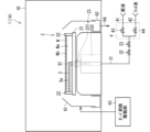
- FIG. 1 is a plan view illustrating an example of a configuration of a substrate processing apparatus.
- FIG. 2 is a plan view illustrating an example of a configuration of a substrate.
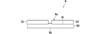
- FIG. 2 is a cross-sectional view illustrating an example of a portion of a configuration of a substrate.
- FIG. 2 is a block diagram illustrating an example of the configuration of a control unit.
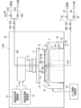
- FIG. 2 is a diagram illustrating a first example of a configuration of a processing unit according to the first embodiment. 4 is a flowchart showing a first example of substrate processing according to the first embodiment.
- FIG. 5A to 5C are diagrams each showing an example of a processing section in each step; 5A to 5C are diagrams each showing an example of a processing section in each step; 1 is a graph showing an example of a change over time in the rotation speed of a substrate.
- FIG. 11 is a plan view illustrating an example of a state in which a first nozzle reciprocates.
- 11A and 11B are diagrams illustrating an example of a state in which a chemical liquid is applied to a liquid film of a rinsing liquid.
- FIG. 4 is a plan view showing the positional relationship between a first nozzle and a substrate.
- 1 is a graph showing the start timing, end timing, and substantial processing time at each position in the circumferential direction on a main surface of a substrate.
- FIG. 4 is a diagram illustrating a second example of the configuration of a processing unit according to the first embodiment.
- 10 is a flowchart showing a second example of the substrate processing according to the first embodiment.
- FIG. 10 is a diagram illustrating an example of a configuration of a processing unit according to a second embodiment.
- 10 is a flowchart showing an example of a substrate processing method according to a second embodiment.
- FIG. 13 is a diagram illustrating an example of a configuration of a processing unit according to a third embodiment.
- FIG. 2 is a cross-sectional view illustrating an example of a portion of a configuration of a substrate.
- an expression indicating an equal state e.g., "same,” “equal,” “homogeneous,” etc.
- the expression not only strictly indicates a state in which the quantitative relationship is equal, but also indicates a state in which a difference exists within a range in which a tolerance or similar function is obtained, unless otherwise specified.
- an expression indicating a shape e.g., "square shape” or “cylindrical shape,” etc.
- the expression not only strictly indicates the shape geometrically, but also indicates a shape having, for example, irregularities or chamfers within a range in which a similar effect is obtained, unless otherwise specified.
- the expression is not an exclusive expression that excludes the presence of other components.
- the expression includes only A, only B, only C, any two of A, B, and C, and all of A, B, and C.
- ⁇ Overall configuration of substrate processing apparatus> 1 is a plan view illustrating an example of the configuration of a substrate processing apparatus 100.
- the substrate processing apparatus 100 is a single-wafer processing apparatus that processes substrates W one by one.
- FIG. 2 is a plan view that shows a schematic example of the configuration of the substrate W
- FIG. 3 is a cross-sectional view that shows a schematic example of a portion of the configuration of the substrate W.
- the substrate W has a plate-like shape. That is, the substrate W has a main surface Wa and a main surface Wb that face each other in the thickness direction.
- the substrate W has a plurality of dies D0 on its main surface Wa.
- the dies D0 are chips that include electronic circuits.
- the dies D0 may also be called semiconductor chips.
- the substrate W includes a support substrate W0 and a plurality of dies D0.
- the support substrate W0 has a plate-like shape.
- the support substrate W0 is not particularly limited, but is, for example, a semiconductor substrate or a glass substrate.
- the support substrate W0 has a disk shape.
- the diameter of the support substrate W0 is, for example, about 300 mm. Both main surfaces of the support substrate W0 are flat, and a plurality of dies D0 are provided on one of the main surfaces of the support substrate W0.
- the multiple dies D0 are arranged two-dimensionally in a planar view.
- Each die D0 has a plate-like shape and is provided on the support substrate W0 with one main surface facing the main surface of the support substrate W0.
- each die D0 may be attached to the support substrate W0 by an adhesive or the like.
- each die D0 has a rectangular shape in a planar view.
- the die D0 has a rectangular shape of, for example, about 10 mm x 10 mm.
- the multiple dies D0 are arranged in a matrix shape with a first direction along one side of the die D0 as the row direction and a second direction intersecting the first direction as the column direction.
- each die D0 may be, for example, 0.1 mm or more, 0.2 mm or more, 0.5 mm or more, or 1 mm or more.
- the minimum value of the spacing between the dies D0 i.e., the gap between the dies D0
- the minimum value of the spacing between the dies D0 may be, for example, 0.1 ⁇ m or more, 1 ⁇ m or more, 10 ⁇ m or more, 100 ⁇ m or more, or 1 mm or more.
- the maximum value of the spacing between the dies D0 may be 2 mm or less.
- the main surface Wa of such a substrate W is composed of a portion of one of the main surfaces of the support substrate W0 that is not covered by the multiple dies D0, and portions of the surfaces of the multiple dies D0 that do not face the support substrate W0.
- an uneven shape is formed on the main surface Wa of the substrate W due to the dies D0.
- each die D0 corresponds to a convex portion. Since the thickness of each die D0 is greater than the thickness of the pattern included in the die D0, the depth of the unevenness formed on the main surface Wa of the substrate W is relatively large.
- the substrate processing apparatus 100 includes an indexer block 110, a processing block 120, and a control unit 90.
- the indexer block 110 is an interface unit for loading and unloading substrates W between the processing block 120 and the outside.
- the processing block 120 is a section that mainly processes the substrates W received from the indexer block 110.
- the control unit 90 is a section that provides overall control of the substrate processing apparatus 100.
- the indexer block 110 includes a plurality of load ports 111 and an indexer robot 112.
- Each load port 111 holds a substrate container (hereinafter, referred to as a carrier C) that is carried in from the outside.
- a plurality of substrates W are stored in the carrier C in a vertically aligned state.
- the indexer robot 112 is a transport unit that transports the substrates W between the carrier C and the processing block 120. The indexer robot 112 sequentially takes out unprocessed substrates W from the carrier C and transports the substrates W to the processing block 120.
- the indexer robot 112 also sequentially receives processed substrates W from the processing block 120, which have been processed by the processing block 120, and stores the substrates W in the carrier C.
- the carrier C that stores the processed substrates W is carried out to the outside from the load port 111.
- the processing block 120 includes one or more processing sections 1 and a center robot 122.
- the processing block 120 includes a plurality of processing sections 1.
- the center robot 122 is a transport unit that transports a substrate W between the indexer robot 112 and the processing sections 1.
- the center robot 122 transports an unprocessed substrate W from the indexer robot 112 into the processing section 1, and transports a processed substrate W that has been processed by the processing section 1 out of the processing section 1.
- the center robot 122 transports the substrate W to another processing section 1 as necessary, and then passes the substrate W to the indexer robot 112.
- Each processing section 1 is a single-wafer processing device that processes substrates W one by one. An example of the specific configuration of the processing section 1 will be described in detail later.
- FIG. 4 is a block diagram showing an example of the configuration of the control unit 90.
- the control unit 90 is an electronic circuit, and has, for example, a data processing unit 91 and a storage unit 92. In the specific example of FIG. 4, the data processing unit 91 and the storage unit 92 are connected to each other via a bus 93.
- the data processing unit 91 may be, for example, an arithmetic processing device such as a CPU (Central Processor Unit).
- the storage unit 92 may have a non-transient storage unit (for example, a ROM (Read Only Memory) or a hard disk) 921 and a temporary storage unit (for example, a RAM (Random Access Memory)) 922.
- the non-transient storage unit 921 may store, for example, a program that specifies the processing to be executed by the control unit 90.
- the data processing unit 91 executes this program, so that the control unit 90 can execute the processing specified in the program.
- a part or all of the processing executed by the control unit 90 may be executed by hardware such as a dedicated logic circuit.
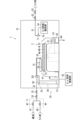
- Fig. 5 is a diagram illustrating a first example of the configuration of the processing section 1 according to the first embodiment. It is not necessary that all processing sections 1 belonging to the substrate processing apparatus 100 have the configuration illustrated in Fig. 5. It is sufficient that at least one processing section 1 of the substrate processing apparatus 100 has the configuration illustrated in Fig. 5.
- the processing unit 1 supplies various processing liquids to the main surface Wa of the substrate W and performs processing on the substrate W (e.g., die D0) according to the processing liquid.
- the processing unit 1 includes a substrate holding unit 2 and a first nozzle 3.
- the processing section 1 also includes a chamber 10.
- the chamber 10 has a box-like shape.
- the internal space of the chamber 10 corresponds to a processing space in which the substrate W is processed.
- the chamber 10 is provided with an openable and closable loading/unloading entrance (not shown).
- the center robot 122 loads an unprocessed substrate W into the chamber 10 through the loading/unloading entrance, and also unloads a processed substrate W from the chamber 10 through the loading/unloading entrance.
- the substrate W is loaded into the chamber 10 with its main surface Wa facing vertically upward.
- the substrate holding unit 2 is provided in the chamber 10.
- the substrate holding unit 2 holds the substrate W in a horizontal position while rotating the substrate W around the rotation axis Q1.
- the horizontal position here means that the thickness direction of the substrate W is along the vertical direction.
- the substrate W is brought in with its main surface Wa facing vertically upward, so the main surface Wa of the substrate W held by the substrate holding unit 2 corresponds to the top surface.
- the substrate holding unit 2 holds the substrate W in a position in which the main surface Wa faces vertically upward.
- the rotation axis Q1 passes through the center of the substrate W and is an axis along the vertical direction.
- Such a substrate holding unit 2 may also be called a spin chuck.
- the substrate holding unit 2 includes a spin base 21, a chuck pin 22, and a rotation drive unit 23.
- the spin base 21 has a plate-like shape (e.g., a disk shape) and is disposed with its thickness direction aligned vertically.
- the chuck pins 22 are provided on the upper surface of the spin base 21.
- the chuck pins 22 are provided, for example, at equal intervals along the circumferential direction about the rotation axis Q1.
- the chuck pins 22 are provided so as to be displaceable between a holding position and a release position, which will be described below.
- the holding position is a position where the chuck pins 22 abut against the periphery of the substrate W.
- the chuck pins 22 hold the substrate W by stopping at their respective holding positions.
- FIG. 2 shows the chuck pins 22 stopped at the holding position.
- the release position is a position where each chuck pin 22 is separated from the substrate W.
- the chuck pins 22 stop at their respective release positions, and thus the substrate W is released from the holding of the substrate W by the chuck pins 22.
- the substrate holding unit 2 also includes a pin drive unit (not shown) that displaces the chuck pins 22.
- the pin drive unit includes a drive source, such as a motor or an air cylinder, and is controlled by the control unit 90.
- the rotation drive unit 23 includes a shaft 231 and a motor 232.
- the upper end of the shaft 231 is connected to the underside of the spin base 21, and the shaft 231 extends from the underside of the spin base 21 along the rotation axis Q1.
- the motor 232 is controlled by the control unit 90, and rotates the shaft 231 around the rotation axis Q1. This causes the spin base 21, chuck pins 22, and substrate W to rotate together around the rotation axis Q1.
- the substrate holding unit 2 does not necessarily have to have a chuck pin 22.
- the substrate holding unit 2 may hold the substrate W using a chuck method such as a vacuum chuck, an electrostatic chuck, or a Bernoulli chuck.
- the first nozzle 3 is provided in the chamber 10 vertically above the substrate W held by the substrate holder 2.
- the first nozzle 3 ejects the processing liquid toward the main surface Wa of the substrate W held by the substrate holder 2.
- the first nozzle 3 can selectively eject the chemical liquid and the rinsing liquid as the processing liquid.
- the first nozzle 3 is connected to the downstream end of the liquid supply pipe 31, the upstream end of the liquid supply pipe 31 is connected to the switching unit 4, and the switching unit 4 is also connected to the downstream end of the chemical liquid supply pipe 41 and the downstream end of the rinsing liquid supply pipe 42.
- the upstream end of the chemical liquid supply pipe 41 is connected to a chemical liquid supply source (not shown), and the upstream end of the rinsing liquid supply pipe 42 is connected to a rinsing liquid supply source (not shown).
- the switching unit 4 is controlled by the control unit 90 to switch the piping connected to the liquid supply pipe 31 between the chemical liquid supply pipe 41 and the rinsing liquid supply pipe 42.
- the switching unit 4 may be, for example, a multiple valve. Specifically, the switching unit 4 may include a chemical valve 43 and a rinse valve 44. These valves are controlled by the control unit 90.
- the chemical valve 43 When the chemical valve 43 is opened, the chemical supply pipe 41 is connected to the liquid supply pipe 31.
- a valve 32 described below is opened in this state, the chemical liquid from the chemical supply source is supplied to the first nozzle 3 through the chemical supply pipe 41, the switching unit 4, and the liquid supply pipe 31, and is discharged from the first nozzle 3.
- the rinse valve 44 is opened, the rinse liquid supply pipe 42 is connected to the liquid supply pipe 31.
- a valve 32 described below is opened in this state, the rinse liquid from the rinse liquid supply source is supplied to the first nozzle 3 through the rinse liquid supply pipe 42, the switching unit 4, and the liquid supply pipe 31, and is discharged from the first nozzle 3.
- the chemical liquid is, for example, a mixture of sulfuric acid and hydrogen peroxide (SPM).
- SPM sulfuric acid and hydrogen peroxide
- the chemical liquid may be a liquid containing at least one of sulfuric acid, acetic acid, nitric acid, hydrochloric acid, hydrofluoric acid, phosphoric acid, acetic acid, ammonia water, hydrogen peroxide, organic acid (for example, citric acid, oxalic acid), organic alkali (for example, TMAH: tetramethylammonium hydroxide), surfactant, and corrosion inhibitor.
- the rinse liquid is, for example, pure water (i.e., deionized water) or carbon dioxide water.
- the chemical supply pipe 41 may be provided with a heater (not shown).
- the heater heats the chemical flowing through the chemical supply pipe 41 to raise the temperature of the chemical to a temperature suitable for processing. For example, when a mixture of sulfuric acid and hydrogen peroxide is used as the chemical, the temperature of the chemical may be adjusted to a range higher than room temperature and lower than 80 degrees Celsius.
- the heater is controlled by the control unit 90.
- a valve 32 and a flow rate control valve 33 are inserted in the liquid supply pipe 31.
- the flow rate control valve 33 adjusts the flow rate of the treatment liquid flowing through the liquid supply pipe 31.
- the flow rate control valve 33 may be a mass flow controller. The valve 32 and the flow rate control valve 33 are controlled by the control unit 90.
- the first nozzle 3 is a shower nozzle. That is, the first nozzle 3 has multiple outlets 3a.
- the first nozzle 3 extends in a direction (e.g., horizontally) along the main surface Wa of the substrate W, and multiple outlets 3a are formed on its underside.
- the multiple outlets 3a are arranged at intervals along the longitudinal direction of the first nozzle 3.
- the multiple outlets 3a may be arranged in a row.
- the number of outlets 3a is not particularly limited, but may be, for example, 10 or more, or 15 or more.
- the outlets 3a may have a circular shape in a plan view, and the diameter may be set to, for example, about several mm.
- the processing section 1 also includes a nozzle movement drive section 34.
- the nozzle movement drive section 34 is controlled by the control section 90 to move the first nozzle 3 within the chamber 10. Specifically, the nozzle movement drive section 34 moves the first nozzle 3 between a first processing position and a first waiting position, which will be described next.
- the first processing position is a position where the first nozzle 3 ejects processing liquid onto the main surface Wa of the substrate W held by the substrate holding section 2, and is a position vertically opposed to the main surface Wa of the substrate W.
- the first nozzle 3 is shown stopped at the first processing position.
- the first waiting position is a position where the first nozzle 3 does not eject processing liquid onto the main surface Wa of the substrate W held by the substrate holding section 2, and is, for example, a position radially outward from the substrate W.
- the first processing position may be a position where the longitudinal direction of the first nozzle 3 is along the radial direction of the rotation axis Q1. In other words, the first processing position may be a position where the multiple outlets 3a of the first nozzle 3 are aligned along the radial direction.
- the outlet 3a of the first nozzle 3 that is closest to the rotation axis Q1 faces the center of the main surface Wa of the substrate W in the vertical direction
- the outlet 3a of the multiple outlets 3a that is farthest from the rotation axis Q1 faces the peripheral portion of the main surface Wa of the substrate W in the vertical direction.
- the distance between the outlet 3a closest to the rotation axis Q1 and the outlet 3a farthest from the rotation axis Q1 may be half or more, two-thirds or more, three-quarters or more, or four-fifths or more of the radius of the substrate W.
- the nozzle movement drive unit 34 includes an arm 35, a support column 36, and a rotation drive unit 37.
- the support column 36 has a columnar shape extending along the vertical direction, and is provided radially outward from the substrate holder 2 in a plan view.
- the arm 35 has a rod-like shape extending along the horizontal direction, and its base end is connected to the support column 36.
- the tip of the arm 35 is provided with a pipe holder 351 through which the liquid supply pipe 31 passes.
- the pipe holder 351 holds the liquid supply pipe 31.
- the rotation drive unit 37 includes a motor (not shown) controlled by the control unit 90, and rotates the support column 36 in the forward and reverse directions within a predetermined angle range around its central axis Q2.
- the first nozzle 3 reciprocates along the circumferential direction about the central axis Q2.
- the nozzle movement drive unit 34 does not necessarily have to have the above configuration, and may include, for example, a linear drive unit such as a ball screw mechanism or a linear motor.
- the processing section 1 also includes a second nozzle 5.
- the second nozzle 5 is provided in the chamber 10, vertically above the substrate W held by the substrate holding section 2.
- the second nozzle 5 ejects the rinsing liquid toward the main surface Wa of the substrate W held by the substrate holding section 2.
- the second nozzle 5 has a shape that extends, for example, vertically, and has an ejection port 5a on its lower surface.
- the second nozzle 5 has a single ejection port 5a.
- the second nozzle 5 is connected to the downstream end of a rinse liquid pipe 51, and the upstream end of the rinse liquid pipe 51 is connected to a rinse liquid supply source (not shown).
- a valve 52 and a flow rate control valve 53 are inserted in the rinse liquid pipe 51.
- the flow rate control valve 53 adjusts the flow rate of the rinse liquid flowing through the rinse liquid pipe 51.
- the flow rate control valve 53 may be a mass flow controller.
- the valve 52 and the flow rate control valve 53 are controlled by the control unit 90.
- the processing section 1 also includes a nozzle movement drive section 54.
- the nozzle movement drive section 54 is controlled by the control section 90 to move the second nozzle 5 between a second processing position and a second waiting position, which will be described below.
- the second processing position is a position where the second nozzle 5 ejects the processing liquid onto the main surface Wa of the substrate W held by the substrate holding section 2, and is, for example, a position vertically opposite the center of the main surface Wa of the substrate W.
- the second waiting position is a position where the second nozzle 5 does not eject the processing liquid onto the main surface Wa of the substrate W held by the substrate holding section 2, and is, for example, a position radially outward from the substrate W.
- FIG. 5 shows the second nozzle 5 stopped at the second waiting position.
- An example of a specific configuration of the nozzle movement drive section 54 is similar to the configuration of the nozzle movement drive section 34.
- the treatment liquid is ejected from the first nozzle 3 or the second nozzle 5 toward the main surface Wa of the rotating substrate W, so that the treatment liquid is supplied to the entire main surface Wa of the substrate W. This allows the substrate W to be treated in accordance with the treatment liquid.
- the processing section 1 also includes a guard 61 and a guard lifting drive section 63.
- the guard 61 has a cylindrical shape that surrounds the substrate W held by the substrate holder 2.
- the guard lifting drive section 63 is controlled by the control section 90 and lifts and lowers the guard 61 between an upper position and a lower position, which will be described below.
- the upper position is a position where the upper end of the guard 61 is vertically above the main surface Wa of the substrate W held by the substrate holder 2.
- FIG. 5 shows the guard 61 stopped at the upper position. When the guard 61 is in the upper position, if the processing liquid splashes from the periphery of the substrate W radially outward, the guard 61 can receive the splashed processing liquid.
- the lower position is a position where the upper end of the guard 61 is vertically lower than the upper position, for example, vertically lower than the upper surface of the spin base 21.
- the guard lifting drive section 63 has, for example, a ball screw mechanism or an air cylinder.
- the cup 62 receives the treatment liquid that has flowed down the inner surface of the guard 61.
- the upstream end of the recovery pipe 64 is connected to the lower part of the cup 62, and the treatment liquid received by the cup 62 is recovered through the recovery pipe 64.
- the cup 62 may be separate from the guard 61, or may be formed integrally with the guard 61.
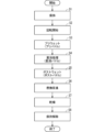
- Fig. 6 is a flow chart showing a first example of the substrate processing according to the first embodiment.
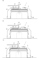
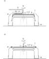
- Figs. 7 and 8 are views each showing an example of the processing section 1 in each step.
- the center robot 122 loads the substrate W into the chamber 10 of the processing section 1, and the substrate holding section 2 receives the substrate W and holds it (step S1: holding process).
- the substrate holding section 2 displaces the multiple chuck pins 22 from their respective release positions to their holding positions. This causes the multiple chuck pins 22 to hold the substrate W.
- the substrate holding section 2 continues to hold the substrate W until the processing of the substrate W is completed.
- the main surface Wa of the substrate W is in a generally dry state when it is loaded into the chamber 10.
- the substrate holder 2 starts rotating the substrate W around the rotation axis Q1 (step S2).
- the substrate holder 2 may maintain the rotation of the substrate W until the processing of the substrate W is completed.
- FIG. 9 is a graph showing an example of the change in the rotation speed (e.g., the target value) of the substrate W over time. The rotation speed of the substrate W at each step will be described later.
- the guard lift drive 63 may raise the guard 61 to the upper position.
- step S3 shows an example of the processing section 1 in step S3.
- the substrate holding section 2 rotates the substrate W at a rotational speed such that the surface of the die D0 of the substrate W is covered with the rinsing liquid L1.
- the substrate holding section 2 rotates the substrate W at a rotational speed of 20 rpm or less.
- the rotational speed of the substrate W may be 15 rpm or less.
- the target value of the rotational speed of the substrate W may be set constant throughout step S3 (see also FIG. 9).
- the control section 9 controls the substrate holding section 2 (specifically, the motor 232) based on the target value so that the rotational speed of the substrate W approaches the target value.
- the processing section 1 supplies the rinse liquid L1 to the main surface Wa of the substrate W while rotating the substrate W at the rotation speed.
- the processing section 1 supplies the rinse liquid L1 to the main surface Wa of the substrate W using the first nozzle 3 or the second nozzle 5 to form a liquid film of the rinse liquid L1 covering the multiple dies D0.
- the first nozzle 3 is used as an example. Specifically, first, the nozzle movement drive section 34 moves the first nozzle 3 to the first processing position. Then, the control section 90 opens the rinse valve 44 and the valve 32. As a result, the rinse liquid L1 is discharged in a continuous flow state from the multiple discharge ports 3a of the first nozzle 3 (see also FIG. 7(a)).
- the flow rate adjustment valve 33 adjusts the flow rate of the rinse liquid L1 to be, for example, 0.1 L (liter)/min or more and 2.0 L/min or less. The flow rate of the rinse liquid L1 may be adjusted to 1.0 L/min or more.
- step S3 the first nozzle 3 ejects the rinse liquid L1 toward the main surface Wa of the substrate W rotating at a low speed. If the rotation speed of the substrate W becomes high, the liquid film of the rinse liquid L1 on the main surface Wa of the substrate W becomes thin, so that at least a part of the surface of the die D0 may be exposed without being covered by the rinse liquid L1.
- the substrate holder 2 rotates the substrate W at a rotation speed of, for example, 20 rpm or less (or 15 rpm) or less. Therefore, the thickness of the liquid film of the rinse liquid L1 is large, and the rinse liquid L1 can cover the surfaces of multiple dies D0.
- the thickness of the liquid film of the rinse liquid L1 between the dies D0 may be greater than or equal to the thickness of the die D0 (see also FIG. 11 described later).
- the liquid film is maintained on the main surface Wa of the substrate W at a low rotation speed, so step S3 can also be said to be a so-called paddle process.
- the pre-wet process is also referred to as the pre-puddle process.
- the nozzle movement drive unit 34 may reciprocate the first nozzle 3 within a predetermined movement range in a direction along the main surface Wa of the substrate W (e.g., horizontal direction). Such reciprocation may also be called swinging.
- FIG. 10 is a plan view that shows an example of the reciprocating movement of the first nozzle 3.
- the predetermined movement range is, for example, a range that includes a reference position in which the longitudinal direction of the first nozzle 3 is along the radial direction of the rotation axis Q1. In FIG. 10, the first nozzle 3 located at the reference position is shown by a solid line.
- the nozzle movement drive unit 34 may move the first nozzle 3 so that the discharge port 3a closest to the rotation axis Q1 reciprocates within a movement range of about ⁇ several tens of mm (e.g., 40 mm) centered on the reference position.
- each landing position moves not only in the circumferential direction about the rotation axis Q1 but also in the radial direction. This allows the processing unit 1 to more uniformly supply the rinsing liquid L1 to the main surface Wa of the substrate W. This allows the processing unit 1 to more quickly form a liquid film of the rinsing liquid L1 with good coverage.
- the processing unit 1 stops the supply of the rinsing liquid L1.
- the control unit 90 executes step S4, which will be described later.
- the pre-time is set in advance and stored, for example, in the memory unit 921. The same applies to the other times, which will be described later.
- the elapsed time is measured, for example, by a timer circuit (not shown) included in the control unit 90.
- step S4 chemical processing step.
- Figures 7(b) and 7(c) show an example of the state of the processing section 1 in step S4.
- Figure 7(b) shows an example of the state of the processing section 1 at the beginning of step S4, and
- Figure 7(c) shows an example of the state of the processing section 1 thereafter.
- the substrate holder 2 rotates the substrate W at a rotational speed of 20 rpm or less.
- the rotational speed of the substrate W may be set to 15 rpm or less.
- the target value of the rotational speed of the substrate W may be set constant throughout step S4 (see also FIG. 9).
- the rotational speed of the substrate W in step S4 is the same as the rotational speed of the substrate W in step S3. However, these rotational speeds may be different from each other.
- the processing unit 1 supplies the chemical liquid L2 to the main surface Wa of the substrate W while it is rotating at a low speed using the first nozzle 3.
- the control unit 90 closes the rinse valve 44 and opens the chemical liquid valve 43 and the valve 32. This causes the chemical liquid L2 to be discharged in a continuous flow from the multiple outlets 3a of the first nozzle 3 toward the main surface Wa of the substrate W (see FIG. 7(b)).
- the flow rate control valve 33 adjusts the flow rate of the chemical liquid L2 to be, for example, not less than 0.1 L/min and not more than 2.0 L/min.
- the flow rate of the chemical liquid L2 may be set to be not less than 1.0 L/min.
- step S4 the first nozzle 3 ejects the chemical liquid L2 toward the main surface Wa of the substrate W that is rotating at a low speed.
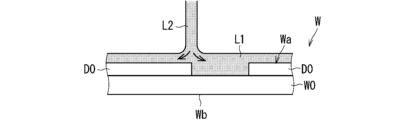
- the chemical liquid L2 lands on the liquid film of the rinsing liquid L1 on the main surface Wa of the substrate W.
- FIG. 11 is a diagram showing an example of how the chemical liquid L2 lands on the liquid film of the rinsing liquid L1. As shown in FIG. 11, the chemical liquid L2 lands on the liquid film of the rinsing liquid L1, so it does not directly land on the corners of the die D0. This makes it possible to suppress splashing of the chemical liquid L2.
- the chemical liquid L2 can flow together with the rinsing liquid L1 on the main surface Wa of the substrate W, the chemical liquid L2 is likely to flow along the main surface Wa of the substrate W. Therefore, even in the early stage of step S4, the chemical liquid L2 can spread more uniformly from each landing position.
- the supply of chemical liquid L2 causes the processing liquid (rinse liquid L1 and chemical liquid L2) on the main surface Wa to overflow from the periphery of the substrate W.
- step S4 because the rotation speed of the substrate W is low, the processing liquid flows down from the periphery of the substrate W without being splashed onto the inner circumferential surface of the guard 61 (see Figures 7(b) and 7(c)).
- the substrate holder 2 rotates the substrate W at a rotation speed that causes the processing liquid from the periphery of the substrate W to flow down without reaching the guard 61.
- the processing liquid that flows down from the periphery of the substrate W is received by the cup 62 and collected through the collection pipe 64.
- the supply of chemical liquid L2 causes the processing liquid to overflow from the main surface Wa of the substrate W, and the processing liquid on the main surface Wa is replaced from the rinsing liquid L1 with the chemical liquid L2.
- the chemical liquid L2 can spread more evenly over the main surface Wa from the beginning of step S4, so that the rinsing liquid L1 can be replaced more evenly with the chemical liquid L2.
- the chemical liquid L2 begins to act on the main surface Wa of the substrate W more evenly.
- the variation in the distribution on the main surface Wa of the start timing at which the chemical liquid L2 begins to act on each position on the main surface Wa of the substrate W can be reduced.
- the first nozzle 3 ejects the chemical solution L2 from multiple outlets 3a arranged along the radial direction, it is possible to effectively reduce the variation in the start timing, particularly in the radial direction.
- step S4 the rotation speed of the substrate W is also low, so that the liquid film of the chemical liquid L2 on the main surface Wa of the substrate W can be made thicker, and the liquid film of the chemical liquid L2 can cover the surfaces of the multiple dies D0 of the substrate W.
- This allows the chemical liquid L2 to act more appropriately on the main surface Wa of the substrate W (particularly the die D0).
- the chemical liquid treatment can be performed appropriately on the main surface Wa of the substrate W.
- the thickness of the liquid film of the chemical liquid L2 between the dies D0 can be greater than or equal to the thickness of the die D0.
- step S4 can also be said to be a so-called paddle treatment.
- the chemical liquid treatment process is also referred to as the chemical liquid puddle process.
- the chemical solution L2 on the main surface Wa of the substrate W reacts with the main surface Wa of the substrate W, and this reaction reduces the active components in the chemical solution L2.
- the reduction in the active components leads to insufficient processing or reduced throughput.
- this reaction also produces foreign matter such as by-products. It is undesirable for foreign matter to remain on the main surface Wa of the substrate W.
- the processing unit 1 may continue to eject the chemical liquid L2 from the first nozzle 3 toward the main surface Wa of the substrate W even after replacing the rinsing liquid L1 with the chemical liquid L2. Since new chemical liquid L2 continues to be supplied to the main surface Wa of the substrate W from the first nozzle 3, the chemical liquid L2 containing sufficient active ingredients reacts with the main surface Wa of the substrate W. This makes it possible to suppress insufficient processing of the main surface Wa of the substrate W. Alternatively, the processing throughput can be improved. Furthermore, foreign matter generated by the reaction flows down from the periphery of the substrate W together with the old chemical liquid L2. This makes it possible to reduce the possibility of foreign matter remaining on the main surface Wa of the substrate W.
- the actual processing time T2 during which the chemical liquid L2 continues to be ejected after the replacement time T1 has elapsed may be set to be longer than the replacement time T1 (see FIG. 9).
- the actual processing time T2 may be 1.5 times or more, 2 times or more, 5 times or more, or 10 times or more of the replacement time T1. This allows the processing using the chemical liquid to be performed sufficiently on the main surface Wa of the substrate W (e.g., die D0).
- the nozzle movement drive unit 34 may move the first nozzle 3 back and forth in the horizontal direction within a predetermined movement range (see FIG. 10).
- the movement range may be the same as the movement range in step S3, for example. If the nozzle movement drive unit 34 moves the first nozzle 3 back and forth, the landing position of the chemical liquid L2 from each discharge port 3a can be moved. This allows the chemical liquid L2 to act more uniformly on the main surface Wa of the substrate W. In particular, depending on the type of chemical liquid L2, processing at the landing position may be promoted more than processing at positions other than the landing position. When such a chemical liquid L2 is used, the back and forth movement of the first nozzle 3 can effectively suppress unevenness in the chemical processing.
- the processing unit 1 stops the supply of the chemical liquid L2.
- a predetermined chemical treatment time T i.e., the sum of the replacement time T1 and the actual treatment time T2
- the control unit 90 executes step S5 described below.
- step S5 post-wet process.
- Figure 8(a) shows an example of the processing section 1 in step S5.
- the substrate holder 2 rotates the substrate W at a rotational speed of 20 rpm or less.
- the rotational speed of the substrate W may be set to 15 rpm or less.
- a target value of the rotational speed of the substrate W may be set constant throughout step S5 (see also FIG. 9).
- the rotational speed of the substrate W in step S5 e.g., a target value
- the rotational speed of the substrate W in step S4 may be the same as the rotational speed of the substrate W in step S4 (e.g., a target value).
- the processing unit 1 supplies rinsing liquid L1 to the main surface Wa of the substrate W rotating at a low speed using the first nozzle 3.
- the control unit 90 closes the chemical liquid valve 43 and opens the rinse valve 44 and valve 32. This causes the rinsing liquid L1 to be discharged in a continuous flow from the multiple outlets 3a of the first nozzle 3 (see FIG. 8(a)).
- the flow rate control valve 33 adjusts the flow rate of the rinsing liquid L1 to be, for example, not less than 0.1 L/min and not more than 2.0 L/min.
- the flow rate of the rinsing liquid L1 may be set to be not less than 1.0 L/min.
- step S4 Since a liquid film of chemical liquid L2 has been formed on the main surface Wa of the substrate W by step S4 immediately before step S5, at the beginning of step S5, the rinsing liquid L1 lands on the liquid film of chemical liquid L2 on the main surface Wa of the substrate W. This makes it possible to suppress splashing of the rinsing liquid L1. Moreover, since the rinsing liquid L1 can flow together with the chemical liquid L2 on the main surface Wa of the substrate W, the rinsing liquid L1 can spread more uniformly from each landing position.
- the supply of rinsing liquid L1 causes the processing liquid (rinsing liquid L1 and chemical liquid L2) on the main surface Wa to overflow from the periphery of the substrate W.
- step S5 because the rotation speed of the substrate W is low, the processing liquid flows down without being splashed onto the inner circumferential surface of the guard 61.
- the substrate holder 2 rotates the substrate W at a rotation speed that allows the processing liquid from the periphery of the substrate W to flow down without reaching the guard 61.
- the processing liquid that flows down from the periphery of the substrate W is received by the cup 62 and collected through the collection pipe 64.
- the supply of rinsing liquid L1 causes the processing liquid to overflow from the main surface Wa of the substrate W, and the processing liquid on the main surface Wa is replaced from the chemical liquid L2 to the rinsing liquid L1.
- the rinsing liquid L1 can spread more evenly over the main surface Wa from the beginning of step S5, so the chemical liquid L2 can be replaced more evenly with the rinsing liquid L1.
- This replacement essentially ends the action of the chemical liquid L2 on each position on the main surface Wa of the substrate W. This makes it possible to reduce the variation in the distribution on the main surface Wa of the stop timing at which the action of the chemical liquid L2 on each position on the main surface Wa of the substrate W ends.
- step S5 Since the rotation speed of the substrate W is also low in step S5, the liquid film of the rinsing liquid L1 on the main surface Wa of the substrate W can be made thicker, and the liquid film of the rinsing liquid L1 can cover the surfaces of the multiple dies D0 of the substrate W.
- the thickness of the liquid film of the rinsing liquid L1 between the dies D0 can be greater than or equal to the thickness of the die D0.
- step S5 since the liquid film is maintained on the main surface Wa of the substrate W at a low rotation speed, step S5 can also be considered a so-called puddle process. For this reason, hereinafter, the post-wet process will also be referred to as the post-puddle process.
- the nozzle movement drive unit 34 may also move the first nozzle 3 back and forth horizontally within a predetermined movement range in step S5 (post-puddle process) (see FIG. 10).
- the movement range may be the same as the movement range in step S4, for example.
- step S5 the processing liquid on the main surface Wa is mostly replaced from the chemical liquid L2 to the rinsing liquid L1.
- the rotation speed of the substrate W is low, a small amount of the chemical liquid L2 may remain on the main surface Wa of the substrate W.
- step S6 replacement promotion process, see also FIG. 9).
- the processing section 1 switches the nozzle that ejects the rinsing liquid L1 from the first nozzle 3 to the second nozzle 5.
- the processing section 1 uses the second nozzle 5 to supply the rinsing liquid L1 to the main surface Wa of the substrate W.
- FIG. 8(b) is a diagram that shows an example of the state of the processing section 1 in step S6.
- the control unit 90 closes the valve 32, causes the nozzle movement drive unit 34 to move the first nozzle 3 to the first standby position, causes the nozzle movement drive unit 54 to move the second nozzle 5 to the second processing position, opens the valve 52, and causes the substrate holder 2 to increase the rotation speed of the substrate W.
- the rinsing liquid L1 is discharged in a continuous flow state from the single discharge port 5a of the second nozzle 5 toward the center of the main surface Wa of the substrate W, which is rotating at a relatively high rotation speed.
- the center here may be, for example, a portion within a circular area having a diameter of one-fifth or less of the diameter of the substrate W.
- the rotation speed of the substrate W may be set, for example, to about 100 rpm or more and 1200 rpm or less, 100 rpm or more and 500 rpm or less, or 200 rpm or more and 500 rpm or less.
- the rinsing liquid L1 that splashes off from the periphery of the substrate W may be received by the inner surface of the guard 61.
- the substrate holder 2 may be rotated at a rotational speed that allows the rinsing liquid L1 to reach the inner surface of the guard 61.
- step S6 the rotation speed of the substrate W is relatively high. Therefore, the centrifugal force generated in the processing liquid on the main surface Wa of the substrate W is relatively large, and the processing liquid tends to flow radially outward. Therefore, the chemical liquid L2 remaining on the main surface Wa of the substrate W also tends to flow radially outward, and is likely to splash (or flow down) outward from the periphery of the substrate W. This improves the efficiency of replacement of the chemical liquid L2 with the rinsing liquid L1.
- step S6 the second nozzle 5 ejects the rinsing liquid L1 toward the center of the main surface Wa of the substrate W.
- the rinsing liquid L1 flows radially outward from the center of the main surface Wa of the substrate W. Therefore, the rinsing liquid L1 can push the processing liquid on the main surface Wa of the substrate W radially outward.
- the chemical liquid L2 remaining on the main surface Wa is pushed radially outward by the rinsing liquid L1, and splashes (or flows down) from the periphery of the substrate W to the outside together with the rinsing liquid L1. This can further improve the efficiency of replacement of the chemical liquid L2 with the rinsing liquid L1.
- the processing unit 1 stops the supply of the rinsing liquid L1. For example, when a predetermined replacement promotion time has elapsed since the rotation speed of the substrate W started to increase, the control unit 90 closes the valve 52. This stops the supply of the rinsing liquid L1 from the second nozzle 5.
- the processing section 1 dries the substrate W (step S7: drying process).
- the substrate holder 2 further increases the rotation speed of the substrate W (so-called spin drying, see also FIG. 9).
- the rotation speed of the substrate W may be set to, for example, greater than 1200 rpm, greater than 1500 rpm, or greater than 2000 rpm. Since the rotation speed of the substrate W is higher than the rotation speed of the substrate W in step S6, the amount of processing liquid that splashes from the periphery of the substrate W can be increased. In addition, the airflow can also promote evaporation of the processing liquid on the substrate W. This allows the substrate W to be dried more quickly.
- the rotation speed of the substrate W in step S6 is lower than the rotation speed of the substrate W in step S7, so splashing of the rinsing liquid L1 can be suppressed in step S6.
- the processing unit 1 stops the rotation of the substrate W. For example, when a predetermined drying time has elapsed since the increase in rotation speed, the substrate holding unit 2 stops the rotation of the substrate W.
- step S8 release step
- the substrate holder 2 displaces the multiple chuck pins 22 from their respective holding positions to the release positions. This releases the substrate W from its hold.
- the center robot 122 removes the substrate W from the processing section 1.
- the processing section 1 can perform various processes on a substrate W whose main surface Wa has an uneven shape using multiple dies D0.
- step S3 the processing section 1 supplies the rinse liquid L1 to the main surface Wa of the substrate W while rotating the substrate W at a rotational speed at which the surfaces of the multiple dies D0 are covered with the rinse liquid L1.
- step S3 because the rotational speed of the substrate W is low, the liquid film of the rinse liquid L1 can be made large enough to cover the surfaces of the multiple dies D0.
- step S4 chemical liquid puddle process
- the processing unit 1 ejects the chemical liquid L2 from the first nozzle 3 toward the main surface Wa of the substrate W while rotating the substrate W at a rotational speed at which the surfaces of the multiple dies D0 are covered with the chemical liquid L2. That is, even in step S4, the chemical liquid L2 lands on the main surface Wa of the substrate W while the rotational speed of the substrate W is low.
- the rotational speed of the substrate W is set, for example, to a value that prevents the chemical liquid L2 from being scattered onto the inner surface of the guard 61. In this way, the chemical liquid L2 lands on the main surface Wa of the substrate W during low-speed rotation, thereby suppressing splashing of the chemical liquid L2.
- a liquid film of rinsing liquid L1 is formed on the main surface Wa of the substrate W in step S3 immediately before step S4. Therefore, at the start of step S4, the chemical liquid L2 from the first nozzle 3 lands on the liquid film of rinsing liquid L1. Therefore, the chemical liquid L2 does not directly land on the corners of the die D0, and splashing of the chemical liquid L2 can be further suppressed. In addition, since the chemical liquid L2 flows together with the rinsing liquid L1 on the main surface Wa of the substrate W, the chemical liquid L2 can spread with high fluidity from the beginning of step S4.
- the chemical liquid L2 may land directly on the corners of the die D0, causing splashing.
- the splashed droplets of the chemical liquid L2 may land at random positions on the main surface Wa of the substrate W.
- the chemical liquid L2 begins to act on the main surface Wa at unintended positions.
- the chemical liquid L2 flows unevenly on the main surface Wa due to the deep unevenness of the main surface Wa. Due to such splashing or uneven flow, positions where the chemical liquid L2 reaches quickly and positions where it is difficult to reach become locally evident.
- the chemical liquid L2 begins to act on the main surface Wa at an earlier timing than other positions.
- the chemical liquid L2 begins to act on the main surface Wa at a later timing than other positions.
- the chemical liquid L2 lands on the liquid film of the rinsing liquid L1 on the main surface Wa of the substrate W while it is rotating at a low speed. This makes it difficult for the chemical liquid L2 to splash, and the chemical liquid L2 spreads more uniformly over the main surface Wa with high fluidity. This allows the chemical liquid L2 to replace the rinsing liquid L1 more uniformly. In other words, it is possible to reduce variation in the start timing. In other words, the processing unit 1 can start chemical processing on the main surface (e.g., die D0) of the substrate W more uniformly.
- step S4 the chemical liquid L2 is discharged from the multiple discharge ports 3a of the first nozzle 3.
- the chemical liquid L2 can be supplied more uniformly to the main surface Wa of the substrate W. This allows the processing section 1 to perform chemical processing on the substrate W more uniformly.
- the multiple discharge ports 3a are aligned roughly along the radial direction, and the chemical liquid L2 is discharged from the multiple discharge ports 3a toward the main surface Wa of the substrate W. In this case, it is possible to more effectively reduce the variation in the start timing at each position on a straight line along the radial direction.
- step S4 the first nozzle 3 moves back and forth within a predetermined range of movement. In this case, the landing position of the liquid from each discharge port 3a varies over time. This also enables the processing section 1 to more uniformly supply the chemical liquid L2 to the main surface Wa of the substrate W, and to perform more uniform chemical processing on the substrate W.
- the processing section 1 can perform chemical processing on the substrate W with a higher throughput while suppressing insufficient processing.
- step S5 post-puddle process
- the processing unit 1 ejects the rinsing liquid L1 from the first nozzle 3 toward the main surface Wa of the substrate W while rotating the substrate W at a rotational speed at which the surfaces of the multiple dies D0 are covered with the rinsing liquid L1.
- the rotational speed of the substrate W is set, for example, to a value that prevents the processing liquid from being splashed onto the inner circumferential surface of the guard 61. In this way, the rinsing liquid L1 lands on the main surface Wa of the substrate W during low-speed rotation, thereby suppressing splashing of the rinsing liquid L1.
- the processing unit 1 can more uniformly replace the processing liquid on the main surface Wa of the substrate W from the chemical liquid L2 to the rinsing liquid L1.
- step S6 replacement promotion process
- the rotation speed of the substrate W in step S6 is set to be higher than the rotation speed of the substrate W in steps S3 to S5.
- the rotation speed of the substrate W in step S6 may be set to a value that allows the processing liquid scattered from the periphery of the substrate W to reach the inner circumferential surface of the guard 61.
- step S6 the second nozzle 5 ejects the rinsing liquid L1 toward the center of the main surface Wa of the substrate W. This causes the rinsing liquid L1 to push the chemical liquid L2 on the main surface Wa of the substrate W from the center radially outward, making it possible to more reliably disperse the chemical liquid L2 from the periphery of the substrate W.
- FIG. 12 is a plan view showing the positional relationship between the first nozzle 3 and the substrate W.
- the rotation direction of the substrate W is indicated by an arrow.
- the substrate W rotates counterclockwise.
- a virtual start line VL1 connecting the landing positions where the chemical liquid L2 first lands and a virtual end line VL2 connecting the landing positions where the chemical liquid L2 last lands are shown.
- each landing position moves relatively toward the upstream side in the rotation direction on a ring-shaped trajectory CL1 centered on the rotation axis Q1 on the main surface Wa of the substrate W.
- the first nozzle 3 stops discharging the chemical liquid L2 from the multiple discharge ports 3a. This causes the last of the chemical liquid L2 to land at each landing position on the end line VL2.
- Region R1 is the region upstream of the start line VL1 in the rotational direction.
- the downstream end of region R1 in the rotational direction is the start line VL1
- the upstream end in the rotational direction is the end line VL2.
- Region R2 is the region upstream of the end line VL2 in the rotational direction.
- the circumferential position of the start line VL1 is determined by the rotational position of the substrate W when the first nozzle 3 starts to eject the chemical liquid L2
- the circumferential position of the end line VL2 is determined by the rotational position of the substrate W when the first nozzle 3 stops ejecting the chemical liquid L2.
- the relative positions of the start line VL1 and the end line VL2 depend on the chemical processing time T for ejecting the chemical liquid L2 and the rotational speed of the substrate W.
- the chemical liquid processing time T may be set according to the rotation speed of the substrate W.
- the chemical liquid processing time T may be set according to the unit time ⁇ T required for one rotation of the substrate W.
- the chemical liquid processing time T may be set so as to satisfy the following formula (1).
- n is an integer and indicates the number of rotations of the substrate W within the chemical processing time T (decimals are rounded down).
- ⁇ is set to, for example, 0.25 or less.
- ⁇ is zero, the chemical treatment time T is set to an integral multiple of the unit time ⁇ T.
- This chemical treatment time T is a preset value.
- the information may be stored in the storage unit 921.
- step S4 chemical puddle step
- step S5 post-puddle step
- the rinsing liquid L1 is also discharged from the first nozzle 3. That is, the nozzles used in steps S4 and S5 are both the first nozzle 3. This allows the processing unit 1 to perform chemical processing on the main surface Wa of the substrate W more uniformly, as will be described below.
- the first nozzle 3 ejects the chemical liquid L2 from multiple outlets 3a arranged along the radial direction.
- the chemical liquid L2 ejected from the multiple outlets 3a lands on the liquid film of the rinsing liquid L1 (see also Figure 11). This allows the chemical liquid L2 to spread quickly from each landing position. Therefore, the chemical liquid L2 is supplied with a very small time difference to each position on a straight line along the radial direction of the main surface Wa of the substrate W. Therefore, for simplicity of explanation, it is assumed here that the chemical liquid L2 is supplied simultaneously on the straight line.
- FIG. 13 is a graph showing the start time t1, end time t2, and effective processing time at each circumferential position on the main surface Wa of the substrate W. The end time t2 and processing time will be described in detail later.
- each circumferential position on the main surface Wa of the substrate W is shown by an angle ⁇ (see also Figure 12), with the start line VL1 being 0 degrees and the direction toward the upstream in the rotational direction being positive.
- the start timing t1 is later the further upstream in the rotational direction from the start line VL1.
- the start timing t1 is proportional to the circumferential position with a proportionality coefficient according to the rotational speed of the substrate W.
- the proportionality coefficient is larger the lower the rotational speed of the substrate W. In other words, when the rotational speed of the substrate W is low, as in this embodiment, the difference between the start timing t1 at the start line VL1 and the start timing t1 at a position immediately downstream in the rotational direction from the start line VL1 becomes larger.
- step S5 post-puddle process
- the timing at which the rinsing liquid L1 begins to land can be understood as the end timing t2.
- the first nozzle 3 ejects the rinsing liquid L1 from multiple outlets 3a aligned along the radial direction. Therefore, for simplicity of explanation, it is assumed here that the rinsing liquid L1 is simultaneously supplied to each position on a straight line along the radial direction of the main surface Wa of the substrate W.
- the end line VL2 is set to 0 degrees. That is, the start line VL1 and the end line VL2 are the same.
- the rinsing liquid L1 gradually lands on the portion that is further away from the end line VL2 on the upstream side of the rotation direction, so the rinsing liquid L1 lands at a later timing the further away the position is from the end line VL2 on the upstream side of the rotation direction. Therefore, as shown in FIG.
- the end timing t2 is later the further away the position is from the end line VL2 on the upstream side of the rotation direction.
- the end timing t2 is proportional to the circumferential position with a proportionality coefficient according to the rotation speed of the substrate W.
- the proportionality coefficient is larger as the rotation speed of the substrate W is lower.
- steps S4 and S5 the processing section 1 ejects the chemical liquid L2 and the rinsing liquid L1 from the same first nozzle 3, respectively. This reduces the variation in the distribution of the effective processing time on the main surface Wa. This allows the processing section 1 to perform chemical processing on the substrate W more uniformly.
- the rotation speed (e.g., a target value) of the substrate W in step S4 and step S5 is the same, ideally, the variation in the effective processing time can be eliminated.
- the effective processing time is shown to be constant regardless of the position on the main surface Wa of the substrate W.
- the two rotation speeds do not have to be completely the same, and may be different.
- the difference between the rotation speed (e.g., a target value) of the substrate W in step S4 and the rotation speed (e.g., a target value) of the substrate W in step S5 may be 50% or less of the rotation speed of the substrate W in step S4, 20% or less, 10% or less, or 5% or less. This makes it possible to more effectively reduce the variation in the effective processing time.
- the control unit 90 may switch the open/closed states of the chemical liquid valve 43 and the rinse valve 44 while continuing to open the valve 32. This allows the first nozzle 3 to eject the rinse liquid L1 continuously in time following the chemical liquid L2.
- the open/closed states of the chemical liquid valve 43 and the rinse valve 44 may be switched within a time difference that allows the first nozzle 3 to eject the rinse liquid L1 continuously into the chemical liquid L2.
- the rinse liquid L1 can be landed with higher positional accuracy with respect to the end line VL2 where the chemical liquid L2 finally lands.
- the flow rate of the chemical liquid L2 in step S4 may be set to be greater than the flow rate of the rinsing liquid L1 in step S3 (pre-puddle step).
- the rotation speed of the substrate W in step S4 may be set to be greater than the rotation speed of the substrate W in step S3. That is, the rotation speed of the substrate W in step S4 may be set to be greater than the rotation speed of the substrate W in step S3 and less than the rotation speed of the substrate W in step S7 (replacement promotion step).
- the flow rate of the chemical liquid L2 is greater and the rotation speed of the substrate W is higher, the old chemical liquid L2 on the main surface Wa of the substrate W is quickly replaced with new chemical liquid L2. Furthermore, by supplying new chemical liquid L2, the concentration distribution of the chemical liquid L2 on the main surface Wa of the substrate W can be made uniform. This makes it possible to improve the uniformity of the chemical processing.
- the processing may be uneven.
- the flow rate of the chemical solution L2 is larger and the rotation speed of the substrate W is higher, the foreign matter can be quickly removed from the main surface Wa of the substrate W. This further improves the uniformity of the chemical processing.
- Fig. 14 is a diagram showing a second example of the configuration of the processing unit 1 according to the first embodiment.
- the processing unit 1 is configured to selectively supply a first chemical liquid (e.g., hydrofluoric acid), a second chemical liquid (e.g., a mixture of sulfuric acid and hydrogen peroxide solution), and a rinsing liquid to the substrate W.
- a first chemical liquid e.g., hydrofluoric acid
- a second chemical liquid e.g., a mixture of sulfuric acid and hydrogen peroxide solution
- the switching unit 4 is connected not only to the upstream end of the liquid supply pipe 31, the downstream end of the liquid supply pipe 41, and the downstream end of the rinsing liquid supply pipe 42, but also to the downstream end of the liquid supply pipe 45.
- the switching unit 4 switches the pipes to be connected to the liquid supply pipe 31 among the liquid supply pipe 41, the liquid supply pipe 45, and the rinsing liquid supply pipe 42.
- the upstream end of the liquid supply pipe 41 is connected to a first chemical supply source (not shown), and the upstream end of the liquid supply pipe 45 is connected to a second chemical supply source (not shown).
- the first chemical liquid and the second chemical liquid are different types of chemical liquids.
- the switching unit 4 may be, for example, a multiple valve. Specifically, the switching unit 4 may include not only the chemical liquid valve 43 and the rinse valve 44, but also the chemical liquid valve 46.
- the chemical liquid valve 43 When the chemical liquid valve 43 is opened, the chemical liquid supply pipe 41 is connected to the liquid supply pipe 31, when the rinse valve 44 is opened, the rinse liquid supply pipe 42 is connected to the liquid supply pipe 31, and when the chemical liquid valve 46 is opened, the chemical liquid supply pipe 45 is connected to the liquid supply pipe 31.
- These valves are controlled by the control unit 90.
- FIG. 15 is a flow chart showing a second example of substrate processing according to the first embodiment.
- the substrate W is loaded into the processing section 1, and the substrate holder 2 holds the substrate W (step S11: holding step).
- step S2 the substrate holder 2 starts rotating the substrate W (step S12: rotation start step).
- step S3 the processing unit 1 supplies a rinse liquid to the main surface Wa of the substrate W rotating at a low speed to form a liquid film of the rinse liquid on the main surface Wa of the substrate W (step S13: pre-wet process (pre-puddle process)).
- step S4 the processing unit 1 ejects the first chemical liquid from the first nozzle 3 toward the main surface Wa of the substrate W rotating at a low speed (step S14: chemical liquid processing process (chemical liquid puddle process)).
- step S14 chemical liquid processing process (chemical liquid puddle process)
- step S5 a process according to the first chemical liquid is performed on the substrate W (e.g., die D0).
- the processing unit 1 supplies a rinse liquid to the main surface Wa of the substrate W rotating at a low speed (step S15: post-wet process (post-puddle process)).
- step S15 post-wet process (post-puddle process)
- the first chemical liquid on the main surface Wa of the substrate W is replaced with the rinse liquid.
- the rotation speed of the substrate W is low in step S15, a small amount of the first chemical liquid may remain on the main surface Wa of the substrate W.
- step S16 replacement promotion step
- step S16 the rotation speed of the substrate W is higher than the rotation speed of the substrate W in steps S13 to S15, so that the liquid film of the rinsing liquid on the main surface Wa of the substrate W becomes thinner, and at least a portion of the upper surface of the die D0 of the substrate W may be exposed.
- the rotation speed of the substrate W in the replacement promotion process may be set to a value such that at least a portion of the upper surface of the die D0 on the main surface Wa of the substrate W is ejected.
- step S17 pre-puddle process
- step S18 chemical liquid puddle process
- step S5 the processing section 1 supplies the rinse liquid to the main surface Wa of the substrate W during low-speed rotation (step S19: post-puddle process). This replaces the second chemical liquid on the main surface Wa of the substrate W with the rinsing liquid.
- step S19 post-puddle process
- step S6 the processing unit 1 then ejects the rinsing liquid from the second nozzle 5 toward the center of the main surface Wa of the substrate W while increasing the rotation speed of the substrate W (step S20: replacement promotion step). This allows the second chemical liquid remaining on the main surface Wa of the substrate W to be more reliably replaced with the rinsing liquid.
- step S7 the processing section 1 increases the rotation speed of the substrate W to dry the substrate W (step S21: drying process).
- step S8 the processing section 1 releases the substrate W from its hold (hold release process), and the center robot 122 removes the substrate W.
- the processing unit 1 can perform a first chemical liquid treatment corresponding to the first chemical liquid and a second chemical liquid treatment corresponding to the second chemical liquid on the substrate W in that order.
- the processing unit 1 performs a set of processes consisting of step S3 (pre-puddle process), step S4 (chemical liquid puddle process), step S5 (post-puddle process), and step S6 (replacement promotion process) multiple times.
- the processing unit 1 supplies different types of chemical liquid to the main surface Wa of the substrate W in each step S4.
- the processing unit 1 repeats the set of processes three or more times.
- Second Embodiment Fig. 16 is a diagram showing a schematic configuration example of a processing section 1 according to the second embodiment.
- the processing section 1 according to the second embodiment will also be referred to as processing section 1A.
- the processing section 1A differs from the processing section 1, for example, in the attitude of the substrate W and the position of the first nozzle 3. Furthermore, in the example of Fig. 16, the processing section 1A is not provided with a second nozzle 5.
- the substrate holding section 2 holds the substrate W in a position in which the main surface Wa faces vertically downward. That is, in the second embodiment, the substrate W is carried into the processing section 1A by the center robot 122 in a position in which the main surface Wa faces vertically downward, and the substrate holding section 2 receives and holds the substrate W in that position.
- the first nozzle 3 is located vertically below the substrate W held by the substrate holding section 2.
- the first nozzle 3 is provided between the main surface Wa of the substrate W and the spin base 21.
- the first nozzle 3 ejects the processing liquid toward the main surface Wa of the substrate W held by the substrate holding section 2.
- the first nozzle 3 extends in a direction along the main surface Wa of the substrate W, and a plurality of ejection ports 3a are formed at the upper portion thereof.
- the first nozzle 3 extends along the radial direction about the rotation axis Q1.
- the plurality of ejection ports 3a are arranged at intervals along the longitudinal direction (i.e., the radial direction) of the first nozzle 3.
- the plurality of ejection ports 3a may be arranged in a row.
- the number of ejection ports 3a is not particularly limited, but may be, for example, 10 or more, or 15 or more.
- the outlet 3a may have, for example, a circular shape in a plan view, and its diameter may be set to, for example, about several mm.
- the first nozzle 3 can selectively discharge the chemical liquid and the rinsing liquid as the processing liquid.
- the first nozzle 3 is connected to the downstream end of the liquid supply pipe 31.
- the shaft 231 is a hollow shaft, and a through hole that penetrates the spin base 21 in the vertical direction is formed in the center of the spin base 21.
- the through hole is connected to the hollow part of the shaft 231.
- the liquid supply pipe 31 penetrates the hollow part of the shaft 231 and the spin base 21, and its upper end (downstream end) protrudes vertically upward from the spin base 21.
- the upper end of the liquid supply pipe 31 is connected to the first nozzle 3.
- the first nozzle 3 extends radially outward from the upper end of the liquid supply pipe 31.
- the lower end (upstream end) of the liquid supply pipe 31 is connected to the switching unit 4, and the switching unit 4 is also connected to the downstream end of the chemical liquid supply pipe 41 and the downstream end of the rinsing liquid supply pipe 42.
- the upstream end of the chemical supply pipe 41 is connected to a chemical supply source, and the upstream end of the rinsing liquid supply pipe 42 is connected to a rinsing liquid supply source.
- the switching unit 4 is controlled by the control unit 90, and switches the piping that is connected to the liquid supply pipe 31 between the chemical supply pipe 41 and the rinsing liquid supply pipe 42.
- the first nozzle 3 may discharge the treatment liquid to the radially outer peripheral region of the main surface Wa of the substrate W at a flow rate greater than the flow rate to the radially inner central region of the main surface Wa of the substrate W.
- the opening area of the outlet 3a located on the radially outer side is greater than the opening area of the outlet 3a located on the radially inner side.
- the opening areas of the multiple outlets 3a may increase monotonically and non-decreasingly toward the radially outer side.
- the opening area of a certain outlet 3a may be equal to or greater than the opening area located radially inner than the outlet 3a.
- the first nozzle 3 can discharge the treatment liquid to the peripheral region, which has a higher movement speed, at a flow rate greater than the central region, so that the treatment liquid can be supplied more uniformly to the main surface Wa of the substrate W.
- the pitch between adjacent outlets 3a of the first nozzle 3 may increase monotonically and non-decreasingly toward the radially outward direction.
- the pitch between two outlets 3a may be equal to or greater than the pitch between two outlets 3a located radially inward of the two outlets 3a.
- FIG. 17 is a flow chart showing an example of substrate processing according to the second embodiment.
- the center robot 122 loads the substrate W into the chamber 10 of the processing section 1A, and the substrate holding section 2 receives and holds the substrate W (step S31: holding process).
- the center robot 122 loads the substrate W into the chamber 10 with the main surface Wa of the substrate W facing vertically downward.
- the substrate holding section 2 holds the substrate W with the main surface Wa facing vertically downward.
- the substrate holding section 2 continues to hold the substrate W until processing of the substrate W is completed.
- the main surface Wa of the substrate W is in a generally dry state when it is loaded into the chamber 10.
- the substrate holder 2 starts rotating the substrate W around the rotation axis Q1 (step S32).
- the substrate holder 2 may maintain the rotation of the substrate W until the processing of the substrate W is completed.
- the guard lift driver 63 may raise the guard 61 to the upper position.
- the processing unit 1A supplies a rinse liquid to the main surface Wa of the substrate W (step S33: pre-wet process).
- the control unit 90 opens the rinse valve 44 and the valve 32. This causes the rinse liquid to be discharged in a continuous flow from the multiple outlets 3a of the first nozzle 3.
- the flow rate of the rinse liquid and the rotation speed of the substrate W are set so that the surface of the die D0 of the substrate W is covered with the rinse liquid.
- the thickness of the parts of the liquid film of the rinse liquid between the dies D0 can be less than the thickness of the die D0.
- step S34 When a predetermined pre-time has elapsed since the start of supplying the rinsing liquid, the control unit 90 executes step S34, which will be described later.
- the processing unit 1A then supplies the chemical liquid to the main surface Wa of the substrate W (step S34: chemical liquid processing process).
- the control unit 90 closes the rinse valve 44 and opens the chemical liquid valve 43 and valve 32. This causes the chemical liquid to be discharged in a continuous flow from the multiple outlets 3a of the first nozzle 3 toward the main surface Wa of the substrate W.
- the flow rate of the chemical liquid and the rotation speed of the substrate W are set so that the surface of the die D0 of the substrate W is covered with the chemical liquid.
- the thickness of the portion of the chemical liquid film between the dies D0 can be less than the thickness of the die D0.
- the processing liquid adhering to the main surface Wa is replaced from the rinsing liquid to the chemical liquid.
- the chemical liquid initially adheres to the liquid film of rinsing liquid adhering to the main surface Wa of the substrate W. This allows the chemical liquid to spread more uniformly over the main surface Wa from the beginning of step S34. Therefore, the processing unit 1A can more uniformly replace the rinsing liquid with the chemical liquid, and the chemical liquid begins to act on the main surface Wa of the substrate W more uniformly. In other words, it is possible to reduce the variation in the distribution on the main surface Wa of the start timing at which the chemical liquid begins to act on each position on the main surface Wa of the substrate W.
- the first nozzle 3 ejects the chemical solution from multiple outlets 3a arranged along the radial direction, it is possible to effectively reduce the variation in start timing, particularly in the radial direction.
- the processing unit 1A stops supplying the chemical.
- the control unit 90 executes step S35, which will be described later.
- the processing unit 1A supplies a rinse liquid to the main surface Wa of the substrate W (step S35: post-wet process).
- the control unit 90 closes the chemical liquid valve 43 and opens the rinse valve 44 and the valve 32. This causes the rinse liquid to be discharged in a continuous flow from the multiple outlets 3a of the first nozzle 3 toward the main surface Wa of the substrate W.
- the flow rate of the rinse liquid and the rotation speed of the substrate W are set so that the surface of the die D0 of the substrate W is covered with the rinse liquid.
- the thickness of the portion of the rinse liquid film between the dies D0 can be less than the thickness of the die D0.
- the processing liquid adhering to the main surface Wa of the substrate W is replaced from the chemical liquid to the rinsing liquid.
- the rinsing liquid can spread more evenly over the main surface Wa from the beginning of step S35, so that the chemical liquid can be replaced more evenly with the rinsing liquid.
- This replacement essentially ends the action of the chemical liquid on each position on the main surface Wa of the substrate W. This makes it possible to reduce the variation in the distribution on the main surface Wa of the stop timing at which the action of the chemical liquid on each position on the main surface Wa of the substrate W ends.
- step S35 the processing liquid adhering to the main surface Wa is replaced from the chemical liquid to the rinsing liquid.
- the processing unit 1A stops the supply of the rinse liquid. For example, when a predetermined post time has elapsed since the start of the supply of the rinse liquid, the control unit 90 closes the rinse valve 44 and the valve 32. This stops the supply of the rinse liquid from the first nozzle 3.
- the processing unit 1A dries the substrate W (step S36: drying step).
- the substrate holder 2 further increases the rotation speed of the substrate W (so-called spin drying).
- the rotation speed of the substrate W may be set to, for example, greater than 1200 rpm, greater than or equal to 1500 rpm, or greater than or equal to 2000 rpm. Since the rotation speed of the substrate W is higher than the rotation speed of the substrate W in steps S33 to S35, the amount of processing liquid that splashes from the periphery of the substrate W can be increased. In addition, the airflow can also promote evaporation of the processing liquid on the substrate W. This allows the substrate W to be dried more quickly.
- the processing unit 1 stops the rotation of the substrate W. For example, when a predetermined drying time has elapsed since the increase in rotation speed, the substrate holding unit 2 stops the rotation of the substrate W.
- step S37 release step
- the substrate holder 2 displaces the multiple chuck pins 22 from their respective holding positions to the release positions. This releases the substrate W from its hold.
- the center robot 122 transports the substrate W out of the processing section 1A.
- the processing section 1A can perform various processes on a substrate W whose main surface Wa has an uneven shape using multiple dies D0.
- the main surface Wa of the substrate W faces vertically downward, and the first nozzle 3 ejects the processing liquid vertically upward from multiple ejection ports 3a to supply the processing liquid to the main surface Wa of the substrate W. Therefore, even if the processing liquid bounces off the unevenness of the main surface Wa of the substrate W, droplets of the rebounded processing liquid head toward the spin base 21. Therefore, the droplets hardly scatter outside the guard 61.
- a liquid film of the rinsing liquid is formed on the main surface Wa of the substrate W in step S33 immediately before step S34. Therefore, at the start of step S34, the chemical liquid from the first nozzle 3 lands on the liquid film of the rinsing liquid. Therefore, the chemical liquid does not land directly on the corners of the die D0, but flows together with the rinsing liquid on the main surface Wa of the substrate W. Therefore, the chemical liquid can spread with high fluidity from the beginning of step S34. Therefore, the chemical liquid is replaced from the rinsing liquid more uniformly. In other words, the variation in the start timing can be reduced. In other words, the processing unit 1A can start the chemical liquid processing on the main surface Wa of the substrate W (e.g., die D0) more uniformly.
- the chemical liquid is discharged from the multiple discharge ports 3a of the first nozzle 3 in step S34.
- the chemical liquid can be supplied more uniformly to the main surface Wa of the substrate W. This allows the processing unit 1A to perform chemical processing on the substrate W more uniformly.
- Third Embodiment 18 is a diagram showing an example of the configuration of the processing section 1 according to the third embodiment.
- the processing section 1 according to the third embodiment will also be referred to as processing section 1B.
- Processing section 1B differs from processing section 1 in terms of a configuration for discharging a processing liquid and the presence or absence of a blocking plate 71.
- the processing section 1B is provided with nozzles 3A and 3B, both of which are examples of the first nozzle 3.
- Nozzle 3B is provided vertically below the substrate W held by the substrate holding section 2.
- the substrate holding section 2 holds the substrate W, for example, with its main surface Wa facing vertically upward.
- the nozzle 3B is provided at a position vertically opposite the center of the substrate W. Specifically, the nozzle 3B protrudes vertically upward from a through hole provided in the center of the spin base 21.
- the nozzle 3B has an outlet 3a at its upper end, and ejects the processing liquid vertically upward from the outlet 3a, that is, toward the center of the main surface Wb of the substrate W.
- Nozzle 3B is connected to the downstream end of liquid supply pipe 31B.
- shaft 231 is a hollow shaft, and liquid supply pipe 31B, like liquid supply pipe 31 of processing unit 1A, passes through spin base 21 and shaft 231 in the vertical direction.
- the lower end (upstream end) of liquid supply pipe 31B is connected to switching unit 4B, which is also connected to the downstream end of chemical liquid supply pipe 41B and the downstream end of rinse liquid supply pipe 42B.
- the upstream end of chemical liquid supply pipe 41B is connected to a chemical liquid supply source, and the upstream end of rinse liquid supply pipe 42B is connected to a rinse liquid supply source.
- Switching unit 4B is controlled by control unit 90 to switch the piping connected to liquid supply pipe 31B between chemical liquid supply pipe 41B and rinse liquid supply pipe 42B.
- the switching unit 4B may be, for example, a multiple valve. Specifically, the switching unit 4B may include a chemical valve 43B and a rinse valve 44B. These valves are controlled by the control unit 90.
- the chemical valve 43B When the chemical valve 43B is opened, the chemical supply pipe 41B communicates with the liquid supply pipe 31B.
- the valve 32B described below When the valve 32B described below is opened in this state, the chemical liquid from the chemical supply source is supplied to the nozzle 3B through the chemical supply pipe 41B, the switching unit 4B, and the liquid supply pipe 31B, and is discharged from the nozzle 3B.
- the rinse valve 44B is opened, the rinse liquid supply pipe 42B communicates with the liquid supply pipe 31B.
- the rinse liquid from the rinse liquid supply source is supplied to the nozzle 3B through the rinse liquid supply pipe 42B, the switching unit 4B, and the liquid supply pipe 31B, and is discharged from the nozzle 3B.
- a valve 32B and a flow rate control valve 33B are inserted in the liquid supply pipe 31B.
- the flow rate control valve 33B adjusts the flow rate of the treatment liquid flowing through the liquid supply pipe 31B.
- the flow rate control valve 33B may be a mass flow controller. The valve 32B and the flow rate control valve 33B are controlled by the control unit 90.
- the blocking plate 71 is also called the opposing plate.
- the blocking plate 71 is provided vertically above the substrate holding part 2 and faces the substrate holding part 2 in the vertical direction.
- the blocking plate 71 has, for example, a circular plate shape, and its lower surface, the opposing surface 71a, faces the substrate holding part 2 in the vertical direction.
- the opposing surface 71a of the blocking plate 71 may be a flat surface, for example, parallel to the horizontal plane.
- the opposing surface 71a has, for example, a circular shape in a plan view.
- the opposing surface 71a may be equal to or larger than the diameter of the substrate W.
- the blocking plate 71 also has the function of holding the substrate W.
- a plurality of chuck pins 72 are provided on the opposing surface 71a of the blocking plate 71.
- the plurality of chuck pins 72 protrude vertically downward from the opposing surface 71a.
- the plurality of chuck pins 72 are provided, for example, at equal intervals along the circumferential direction about the rotation axis Q1.
- the plurality of chuck pins 72 are provided so as to be displaceable between a holding position and a release position, which will be described next.
- the holding position is a position where the chuck pin 72 abuts against the periphery of the substrate W.
- the plurality of chuck pins 72 hold the substrate W by stopping at their respective holding positions. For this reason, the holding position of each chuck pin 72 is located on a circumference that is the same as the diameter of the substrate W.
- the release position is a position where each chuck pin 72 is separated from the substrate W. In other words, the release position of each chuck pin 72 is located on a circumference that is larger than the diameter of the substrate W.
- the multiple chuck pins 72 stop at their respective release positions, thereby releasing the holding of the substrate W by the chuck pins 72. In the example of FIG. 18, the chuck pins 72 are shown positioned at the release positions.
- the processing section 1B is provided with a pin drive unit (not shown) that displaces the chuck pins 72.
- the pin drive unit includes a drive source such as a motor or an air cylinder, and is controlled by the control unit 90.
- a support shaft 73 is provided on the upper surface of the blocking plate 71.
- the support shaft 73 is provided, for example, on the rotation axis Q1.
- a through hole extending along the rotation axis Q1 is formed in the support shaft 73 and the blocking plate 71, and a liquid supply pipe 31A is arranged in the through hole.
- a nozzle 3A is connected to the lower end of the liquid supply pipe 31A.
- the nozzle 3A is provided at a position facing the center of the substrate W.
- the nozzle 3A has an outlet 3Aa at its lower end, and the processing liquid is discharged from the outlet 3Aa.
- the upstream end of the liquid supply pipe 31A is connected to the switching unit 4A, which is also connected to the downstream end of the chemical liquid supply pipe 41A and the downstream end of the rinsing liquid supply pipe 42A.
- the upstream end of the chemical liquid supply pipe 41A is connected to a chemical liquid supply source, and the upstream end of the rinsing liquid supply pipe 42A is connected to a rinsing liquid supply source.
- the switching unit 4A is controlled by the control unit 90, and switches the piping that is connected to the liquid supply pipe 31A between the chemical liquid supply pipe 41A and the rinsing liquid supply pipe 42A.
- the switching unit 4A may be, for example, a multiple valve. Specifically, the switching unit 4A may include a chemical valve 43A and a rinse valve 44A. These valves are controlled by the control unit 90.
- the chemical valve 43A When the chemical valve 43A is opened, the chemical supply pipe 41A is connected to the liquid supply pipe 31A.
- the valve 32A described below When the valve 32A described below is opened in this state, the chemical liquid from the chemical supply source is supplied to the nozzle 3A through the chemical supply pipe 41A, the switching unit 4A, and the liquid supply pipe 31A, and is discharged from the nozzle 3A.
- the rinse valve 44A is opened, the rinse liquid supply pipe 42A is connected to the liquid supply pipe 31A.
- the rinse liquid from the rinse liquid supply source is supplied to the nozzle 3A through the rinse liquid supply pipe 42A, the switching unit 4A, and the liquid supply pipe 31A, and is discharged from the nozzle 3A.
- a valve 32A and a flow rate control valve 33A are inserted in the liquid supply pipe 31A.
- the flow rate control valve 33A adjusts the flow rate of the treatment liquid flowing through the liquid supply pipe 31A.
- the flow rate control valve 33A may be a mass flow controller.
- the valve 32A and the flow rate control valve 33A are controlled by the control unit 90.
- processing section 1B is provided with a barrier plate lifting drive section 75 and a barrier plate rotation drive section 74.
- the barrier plate lifting drive section 75 raises and lowers the barrier plate 71, nozzle 3A, liquid supply pipe 31A and support shaft 73 together between the processing position and the standby position.
- the processing position is a position close to the substrate holder 2, and the standby position is a position vertically above the processing position.
- the barrier plate lifting drive section 75 includes, for example, a drive source such as a motor and a power transmission section such as a ball screw mechanism.
- the barrier plate lifting drive section 75 is controlled by the control section 90.
- the barrier plate rotation drive unit 74 rotates the barrier plate 71 around the rotation axis Q1.
- the barrier plate rotation drive unit 74 may rotate the support shaft 73 and the barrier plate 71 around the rotation axis Q1.
- the barrier plate rotation drive unit 74 includes a drive source such as a motor.
- the barrier plate rotation drive unit 74 is controlled by the control unit 90.
- step S31 to step S34 differ from the operation of the processing unit 1A in the second embodiment.
- the shield plate 71 receives and holds the substrate W from the center robot 122.
- the center robot 122 moves the hand to a position where the center of the substrate W placed on the hand coincides with the rotation axis Q1.
- the shield plate lifting drive unit 75 lowers the shield plate 71 to a receiving position where the multiple chuck pins 72 are horizontally adjacent to the substrate W on the hand.
- the processing unit 1B moves the multiple chuck pins 72 to a holding position.
- the multiple chuck pins 72 hold the substrate W.
- the center robot 122 retracts the hand from the chamber 10.
- the shield plate lifting drive unit 75 lowers the shield plate 71 to the processing position.
- the processing position is a position where the chuck pins 22 of the substrate holder 2 move to the holding position, allowing the substrate holder 2 to hold the substrate W.
- step S32 rotation start process
- the rotation drive unit 23 and the barrier plate rotation drive unit 74 start rotating the spin base 21 and the barrier plate 71 around the rotation axis Q1, respectively.
- the rotation directions of the spin base 21 and the barrier plate 71 are, for example, the same, and the rotation drive unit 23 and the barrier plate rotation drive unit 74 rotate the spin base 21 and the barrier plate 71 synchronously, for example.
- the chuck pins 22 located in the release position are radially outward of the chuck pins 72 located in the holding position. Therefore, even if the rotation speeds or directions of the spin base 21 and the barrier plate 71 are different, the processing unit 1B can rotate the barrier plate 71 and the spin base 21 while avoiding collisions between the chuck pins 22 and chuck pins 72.
- processing unit 1B supplies rinsing liquid to substrate W, filling the first space between opposing surface 71a of blocking plate 71 and main surface Wa of substrate W with the rinsing liquid.
- control unit 90 opens valve 32A, rinse valve 44A, valve 32B, and rinse valve 44B.
- rinsing liquid is ejected in a continuous flow state from nozzle 3A toward main surface Wa of substrate W
- rinsing liquid is ejected in a continuous flow state from nozzle 3B toward main surface Wb of substrate W.
- the rinse liquid discharged from the nozzle 3A lands on the center of the main surface Wa of the substrate W, flows radially outward due to the centrifugal force generated by the rotation of the substrate W, and splashes (or flows down) outward from the periphery of the substrate W.
- the rinse liquid fills the first space between the opposing surface 71a and the main surface Wa. In other words, the first space between the opposing surface 71a and the main surface Wa becomes liquid-tight due to the rinse liquid.
- the gap between the opposing surface 71a and the main surface Wa and the flow rate of the rinse liquid from the nozzle 3A are set to a level that can realize a liquid-tight state of the first space. Since the gap between the opposing surface 71a and the main surface Wa is narrow, the rinse liquid filling the first space can be said to form a liquid film.
- the rinse liquid discharged from nozzle 3B lands on the center of the main surface Wb of the substrate W, flows radially outward due to the centrifugal force generated by the rotation of the substrate W, and splashes (or flows down) outward from the periphery of the substrate W.
- the rinse liquid fills the second space between the substrate W and the spin base 21.
- the second space between the substrate W and the spin base 21 is liquid-tight due to the rinse liquid.
- the gap between the substrate W and the spin base 21 and the flow rate of the rinse liquid from nozzle 3B are set to a level that can realize a liquid-tight state of the second space. Note that since the gap between the main surface Wa of the substrate W and the upper surface of the spin base 21 is narrow, the rinse liquid filling the second space can also be said to form a liquid film.
- step S33 the rotation speeds of the blocking plate 71 and the spin base 21 may be different from each other, and the rotation directions of the blocking plate 71 and the spin base 21 may be opposite to each other. This makes it possible to agitate the liquid film of the rinsing liquid. Therefore, even if air bubbles are present in the liquid film of the rinsing liquid, the air bubbles can be efficiently crushed.
- the processing unit 1B stops supplying the rinsing liquid.
- the control unit 90 executes step S34 when a predetermined pre-time has elapsed since the start of supplying the rinsing liquid.
- step S34 the processing unit 1B supplies the chemical liquid to the substrate W to fill the first space between the opposing surface 71a of the blocking plate 71 and the main surface Wa of the substrate W.
- the control unit 90 closes the rinse valve 44A and the rinse valve 44B, and opens the valve 32A, the chemical liquid valve 43A, the valve 32B, and the chemical liquid valve 43B.
- the chemical liquid is discharged from the nozzle 3A toward the main surface Wa of the substrate W, and the chemical liquid is discharged from the nozzle 3B toward the main surface Wb of the substrate W. Therefore, the chemical liquid is filled in the first space between the blocking plate 71 and the substrate W, while filling the second space between the substrate W and the spin base 21.
- a liquid film of the chemical liquid is formed in the first space, while a liquid film of the chemical liquid is also formed in the second space.
- the processing liquid in the first space and the second space is replaced from the rinsing liquid to the chemical liquid.
- the chemical liquid can spread more evenly over the main surface Wa from the beginning of step S34, so that the rinsing liquid can be replaced more evenly with the chemical liquid.
- the chemical liquid begins to act on the main surface Wa of the substrate W more evenly. In other words, it is possible to reduce the variation in the distribution on the main surface Wa of the start timing at which the chemical liquid begins to act on each position on the main surface Wa of the substrate W.
- the rotation speeds of the blocking plate 71 and the spin base 21 may be changed over time to be different from each other, or the rotation directions of the blocking plate 71 and the spin base 21 may be switched alternately. This causes the relative rotation state between the blocking plate 71 and the spin base 21 to change over time. This makes it possible to effectively agitate the liquid film of the chemical liquid in the second space between the main surface Wb of the substrate W held by the blocking plate 71 and the spin base 21. Therefore, even if air bubbles are present in the liquid film of the chemical liquid in the second space, the air bubbles can be efficiently crushed.
- the processing section 1B transfers the substrate W from the blocking plate 71 to the substrate holding section 2. Specifically, first, the control section 90 closes the chemical valve 43B. This releases the liquid-tight state of the second space between the main surface Wb of the substrate W and the spin base 21. Then, the control section 90 stops the rotation of the blocking plate 71 and the substrate holding section 2. At this time, the control section 90 stops the multiple chuck pins 72 of the blocking plate 71 and the multiple chuck pins 22 of the substrate holding section 2 so that they are different in the circumferential direction. Next, the processing section 1B moves the multiple chuck pins 22 of the substrate holding section 2 to their respective holding positions, and then moves the multiple chuck pins 72 of the blocking plate 71 to their respective release positions. This allows the substrate W to be transferred from the blocking plate 71 to the substrate holding section 2.
- the processing section 1B rotates the blocking plate 71 and the spin base 21 of the substrate holder 2 again, and the control section 90 opens the chemical valve 43B. This makes the second space liquid-tight again.
- the rotational speeds of the blocking plate 71 and the spin base 21 may be changed over time to be different from each other, and the rotational directions of the blocking plate 71 and the spin base 21 may be switched alternately.
- This causes the relative rotational state between the blocking plate 71 and the spin base 21 to change over time, so that the liquid film of the chemical liquid in the first space between the opposing surface 71a of the blocking plate 71 and the main surface Wa of the substrate W held by the substrate holding part 2 can be effectively agitated. Therefore, even if air bubbles are present in the liquid film of the chemical liquid in the first space, the air bubbles can be efficiently crushed.
- the processing unit 1B stops the supply of the chemical.
- the control unit 90 executes step S35.
- step S35 the processing unit 1B supplies the rinse liquid to the substrate W to fill the first space between the opposing surface 71a of the blocking plate 71 and the main surface Wa of the substrate W with the rinse liquid.
- the control unit 90 closes the chemical liquid valve 43A and the chemical liquid valve 43B, and opens the valve 32A, the rinse valve 44A, the valve 32B, and the rinse valve 44B.
- the rinse liquid is discharged from the nozzle 3A toward the main surface Wa of the substrate W
- the rinse liquid is discharged from the nozzle 3B toward the main surface Wb of the substrate W.
- the rinse liquid pushes the chemical liquid in the first space between the blocking plate 71 and the substrate W radially outward, while pushing the chemical liquid in the second space between the substrate W and the spin base 21 radially outward.
- a liquid film of the rinse liquid is formed in the first space, and a liquid film of the rinse liquid is also formed in the second space.
- the rinsing liquid in the first space can be agitated by the relative rotation of the blocking plate 71 and the substrate W.
- the rinsing liquid in the first space can be agitated more effectively. This makes it possible to more effectively replace the liquid in the first space from the chemical liquid to the rinsing liquid.
- the processing section 1B transfers the substrate W from the substrate holder 2 to the shield plate 71. This transfer is performed, for example, by displacing the chuck pins 22 and 72 with the rinse valve 44B closed.
- the control section 90 then opens the rinse valve 44B, causing the nozzle 3B to eject the rinse liquid again. This causes the second space to become liquid-tight again.
- the rinsing liquid in the second space can be agitated by the relative rotation of the substrate W and the spin base 21.
- the rinsing liquid in the second space can be agitated more effectively. This makes it possible to more effectively replace the liquid in the second space from the chemical liquid to the rinsing liquid.
- processing unit 1B stops the supply of rinse liquid.
- control unit 90 closes valve 32A, rinse valve 44A, valve 32B, and rinse valve 44B.
- step S36 drying step
- the processing unit 1B dries the substrate W.
- the substrate holder 2 further increases the rotation speed of the substrate W (so-called spin drying).
- the rotation speed of the substrate W may be set to, for example, greater than 1200 rpm, greater than 1500 rpm, or greater than 2000 rpm. Since the rotation speed of the substrate W is higher than the rotation speed of the substrate W in steps S33 to S35, the amount of processing liquid that splashes from the periphery of the substrate W can be increased.
- the airflow can also promote evaporation of the processing liquid on the substrate W. This allows the substrate W to be dried more quickly.
- the processing section 1B may include a first gas supply section (not shown) that ejects an inert gas from a first gas ejection port (not shown) formed on the opposing surface 71a of the blocking plate 71 toward the main surface Wa of the substrate W, and a second gas supply section (not shown) that ejects an inert gas from a second gas ejection port (not shown) formed on the upper surface of the spin base 21 toward the main surface Wb of the substrate W.
- the first gas supply section and the second gas supply section may eject an inert gas in step S36. This can promote drying of the substrate W.
- the processing unit 1 stops the rotation of the substrate W. For example, when a predetermined drying time has elapsed since the increase in rotation speed, the substrate holding unit 2 stops the rotation of the substrate W.
- processing section 1B releases its hold on the substrate W. Specifically, first, shield plate lifting drive section 75 raises shield plate 71 to the transfer position, and center robot 122 moves its hand to the transfer position. Processing section 1B then displaces multiple chuck pins 72 from their respective holding positions to the release position, and transfers the substrate W to the hand of center robot 122. Then, center robot 122 retracts its hand from chamber 10, thereby removing the substrate W from processing section 1B.
- the processing section 1B can perform various processes on a substrate W whose main surface Wa has an uneven shape using multiple dies D0.
- a liquid film of the rinsing liquid is also formed on the main surface Wa of the substrate W (i.e., the first space) in step S33 immediately before step S34. Therefore, at the start of step S34, the chemical liquid from the first nozzle 3 is supplied to the liquid film of the rinsing liquid. Therefore, the chemical liquid does not land directly on the corner of the die D0, but flows together with the rinsing liquid on the main surface Wa of the substrate W. Therefore, the chemical liquid can spread with high fluidity from the beginning of step S34. Therefore, the chemical liquid is replaced from the rinsing liquid more uniformly. In other words, the variation in the start timing can be reduced. In other words, the processing unit 1B can start the chemical liquid processing on the main surface Wa of the substrate W (e.g., die D0) more uniformly.
- the processing section 1B supplies the chemical liquid while the first space between the blocking plate 71 and the substrate W is filled with the rinsing liquid. That is, while the outlet 3Aa of the nozzle 3A is in contact with the film of the rinsing liquid, the chemical liquid is discharged from the outlet 3Aa into the film of the rinsing liquid. As a result, the chemical liquid spreads through the film of the rinsing liquid, and it is possible to prevent the chemical liquid from splashing due to unevenness on the main surface Wa of the substrate W. Therefore, droplets hardly scatter outside the guard 61.
- FIG. 19 is a cross-sectional view that shows an example of a part of the configuration of the substrate W.
- a recess Wr is formed on the surface of the support substrate W0 of the substrate W on which the die D0 is provided.
- a part of the die D0 is inserted into the recess Wr.
- the recess Wr has a rectangular shape similar to that of the die D0 in a plan view.
- the depth of the die D0 may be set to, for example, one-fifth or less of the thickness of the die D0, or may be set to one-tenth or less.
- the depth of the recess Wr may be set to about 15 ⁇ m.
- a plurality of recesses Wr are formed in the support substrate W0 corresponding to the plurality of dies D0.
- the plurality of recesses Wr are arranged in a matrix, for example.
- the recesses Wr are arranged in the same manner as the die D0 in FIG. 2.
- the substrate processing apparatus 100 and substrate processing method according to the first to third embodiments can also be applied to the substrate W illustrated in FIG. 19.
- the substrate processing apparatus 100 and substrate processing method according to the first to third embodiments may also be applied to the support substrate W0.
- the substrate processing apparatus 100 and substrate processing method according to any of the first to third embodiments may be applied to the support substrate W0 before the die D0 is placed on it.
- the chemical liquid and the rinsing liquid are ejected from a common first nozzle 3, but the processing section 1 may include a first nozzle 3 for the chemical liquid and a first nozzle 3 for the rinsing liquid separately.
- the shapes of the first nozzle 3 for the chemical liquid and the first nozzle 3 for the rinsing liquid may be the same. More specifically, the shape, size, number and pitch of the multiple ejection ports 3a may be common between the first nozzle 3 for the chemical liquid and the first nozzle 3 for the rinsing liquid.
- the processing unit 1 may include a first nozzle 3 for the first chemical liquid and the rinsing liquid, and a first nozzle 3 for the second chemical liquid and the rinsing liquid separately. Furthermore, the processing unit 1 may include a first nozzle 3 for the first chemical liquid, a first nozzle 3 for the second chemical liquid, and a first nozzle 3 for the rinsing liquid separately. The shapes of these first nozzles 3 may be the same.
- the first nozzle 3 is a nozzle having a plurality of outlets 3a arranged in a line, but it may also be a flat nozzle in which the plurality of outlets 3a are two-dimensionally distributed in a plan view.
- This first nozzle 3 can supply the processing liquid over a wider range to the main surface Wa of the substrate W.
- This first nozzle 3 may also be called a full-surface nozzle.
- the rinse liquid used in step S3 may be a different type of rinse liquid from the rinse liquid used in step S5 (post-wet process).
- the second space between the substrate W and the spin base 21 is also liquid-tight with the processing liquid, but this is not necessarily limited to this.
- the nozzle 3B does not have to eject the processing liquid.
- the nozzle 3B does not have to be provided.
- the blocking plate 71 does not have to have the function of holding the substrate W.
- the multiple chuck pins 72 do not have to be provided. In this case, the substrate holding unit 2 continues to hold the substrate W in steps S33 to S35.
- Blocking plate 71a Opposing surface D0 Die L1 Rinse liquid L2 Chemical liquid S1, S11 Holding step (step) S3, S13, S17 Pre-wet process, pre-puddle process (steps) S33 Pre-wet process S34 Chemical solution treatment process S35 Post-wet process S4, S14, S18 Chemical solution treatment process, chemical solution puddle process (step) S5, S15, S19 Post-wet process, post-puddle process (step) S6, S16, S20 Replacement promotion step (step) S7, S21 Drying process (step) T Chemical solution processing time T1 Replacement time T2 Actual processing time W Substrate Wa Main surface ⁇ T Unit time
Landscapes
- Cleaning Or Drying Semiconductors (AREA)
- Application Of Or Painting With Fluid Materials (AREA)
- Mechanical Treatment Of Semiconductor (AREA)
Abstract
Description
図1は、基板処理装置100の構成の一例を概略的に示す平面図である。基板処理装置100は、基板Wを1枚ずつ処理する枚葉式の処理装置である。
図1の例では、インデクサブロック110は、複数のロードポート111と、インデクサロボット112とを含む。各ロードポート111は、外部から搬入された基板収容器(以下、キャリアCと呼ぶ)を保持する。キャリアCには、複数の基板Wが鉛直方向に並んだ状態で収容される。インデクサロボット112は、キャリアCと処理ブロック120との間で基板Wを搬送する搬送ユニットである。インデクサロボット112はキャリアCから未処理の基板Wを順次に取り出し、該基板Wを処理ブロック120に搬送する。また、インデクサロボット112は、処理ブロック120によって処理された処理済みの基板Wを処理ブロック120から順次に受け取り、該基板WをキャリアCに収容する。処理済みの複数の基板Wを収容したキャリアCはロードポート111から外部に搬出される。
図1の例では、処理ブロック120は、1つ以上の処理部1と、センターロボット122とを含んでいる。図1の例では、処理ブロック120は複数の処理部1を含む。センターロボット122は、インデクサロボット112および処理部1の間で基板Wを搬送する搬送ユニットである。センターロボット122はインデクサロボット112からの未処理の基板Wを処理部1に搬入し、処理部1によって処理された処理済みの基板Wを処理部1から搬出する。センターロボット122は、必要に応じて基板Wを他の処理部1に搬送した後に、基板Wをインデクサロボット112に渡す。
制御部90は、基板処理装置100を統括的に制御する。具体的には、制御部90はインデクサロボット112、センターロボット122および処理部1を制御する。図4は、制御部90の構成の一例を概略的に示すブロック図である。制御部90は電子回路であって、例えばデータ処理部91および記憶部92を有している。図4の具体例では、データ処理部91と記憶部92とはバス93を介して相互に接続されている。データ処理部91は例えばCPU(Central Processor Unit)などの演算処理装置であってもよい。記憶部92は非一時的な記憶部(例えばROM(Read Only Memory)またはハードディスク)921および一時的な記憶部(例えばRAM(Random Access Memory))922を有していてもよい。非一時的な記憶部921には、例えば制御部90が実行する処理を規定するプログラムが記憶されていてもよい。データ処理部91がこのプログラムを実行することにより、制御部90が、プログラムに規定された処理を実行することができる。もちろん、制御部90が実行する処理の一部または全部が専用の論理回路などのハードウェアによって実行されてもよい。
図5は、第1実施形態にかかる処理部1の構成の第1例を概略的に示す図である。なお、基板処理装置100に属する全ての処理部1が、図5に例示された構成を有している必要はない。基板処理装置100の少なくとも一つの処理部1が、図5に例示された構成を有していればよい。
図6は、第1実施形態にかかる基板処理の第1例を示すフローチャートである。図7および図8は、各ステップにおける処理部1の様子の一例を概略的に示す図である。
ステップS4(薬液パドル工程)における基板Wの回転速度は低いので、第1ノズル3が薬液L2の吐出を開始する時点での基板Wの回転位置と、第1ノズル3が薬液L2の吐出を停止する時点での基板Wの回転位置との間のずれが、薬液処理の均一性に大きく影響する。以下に、具体的に説明する。なお以下では、説明の簡単のために、ステップS4において、第1ノズル3を往復移動させないものとする。
ここで、nは整数であり、薬液処理時間T内において基板Wが回転する回数(小数点は切り下げ)を示す。αは例えば0,25以下に設定される。式(1)によれば、薬液処理時間Tと単位時間ΔTの整数倍(=n・ΔT)との差が、単位時間ΔTの4分の1以下となるように、薬液処理時間Tが設定される。αは例えば0.2に設定されてもよく、0.1に設定されてもよい。αが小さく設定されるほど、開始線VL1と終了線VL2との差(角度)を小さくすることができる。つまり、αを小さく設定するほど、薬液処理の均一性を向上させることができる。αがゼロである場合には、薬液処理時間Tは単位時間ΔTの整数倍に設定される。この薬液処理時間Tは予め設定されて、例えば記憶部921に記憶されてもよい。
上述の具体例では、ステップS4(薬液パドル工程)では、第1ノズル3から薬液L2が吐出され、ステップS5(ポストパドル工程)では、同じく第1ノズル3からリンス液L1が吐出される。つまり、ステップS4およびステップS5で用いられるノズルはいずれも第1ノズル3である。これによれば、以下に説明するように、処理部1はさらに均一に基板Wの主面Waに対して薬液処理を行うことができる。
ステップS4(薬液パドル工程)における薬液L2の流量を、ステップS3(プリパドル工程)におけるリンス液L1の流量よりも大きく設定してもよい。さらに、ステップS4における基板Wの回転速度を、ステップS3における基板Wの回転速度よりも高く設定してもよい。つまり、ステップS4における基板Wの回転速度を、ステップS3における基板Wの回転速度よりも高く、かつ、ステップS7(置換促進工程)における基板Wの回転速度よりも低く設定してもよい。
上述の具体例では、処理部1は1種類の薬液を用いた薬液処理を行うものの、複数種類の薬液を用いた薬液処理を基板Wに対して順次に行ってもよい。図14は、第1実施形態にかかる処理部1の構成の第2例を概略的に示す図である。図14の例では、処理部1は、第1薬液(例えばフッ酸)、第2薬液(例えば硫酸と過酸化水素水の混合液)およびリンス液を選択的に基板Wに供給可能に構成されている。具体的には、切換部4は、給液管31の上流端、薬液供給管41の下流端およびリンス液供給管42の下流端のみならず、薬液供給管45の下流端にも接続されている。切換部4は、給液管31に連通させる配管を、薬液供給管41、薬液供給管45およびリンス液供給管42の間で切り替える。薬液供給管41の上流端は第1薬液供給源(不図示)に接続され、薬液供給管45の上流端は第2薬液供給源(不図示)に接続される。第1薬液および第2薬液は互いに異なる種類の薬液である。
図16は、第2実施形態にかかる処理部1の構成の一例を概略的に示す図である。以下では、第2実施形態にかかる処理部1を処理部1Aとも呼ぶ。処理部1Aは、例えば、基板Wの姿勢および第1ノズル3の位置という点で処理部1と相違する。また、図16の例では、処理部1Aには第2ノズル5が設けられていない。
図18は、第3実施形態にかかる処理部1の構成の一例を概略的に示す図である。以下では、第3実施形態にかかる処理部1を処理部1Bとも呼ぶ。処理部1Bは、処理液を吐出する構成および遮断板71の有無という点で処理部1と相違している。
第4実施形態では、基板Wの別の種類の一例について説明する。図19は、基板Wの構成の一部の一例を概略的に示す断面図である。図19の例では、基板Wの支持基板W0のうちのダイD0が設けられる面には、凹部Wrが形成されている。凹部WrにはダイD0の一部が挿入される。凹部Wrは平面視においてダイD0と同様の矩形形状を有する。ダイD0の深さは、例えば、ダイD0の厚みの5分の1以下に設定されてもよく、10分の1以下に設定されてもよい。具体的な一例として、凹部Wrの深さは15μm程度に設定され得る。支持基板W0には、複数のダイD0に対応して複数の凹部Wrが形成される。複数の凹部Wrは例えばマトリックス状に配列される。例えば図2のダイD0と同様に凹部Wrが配列される。
3a,3Aa 吐出口
71 遮断板
71a 対向面
D0 ダイ
L1 リンス液
L2 薬液
S1,S11 保持工程(ステップ)
S3,S13,S17 プリウェット工程、プリパドル工程(ステップ)
S33 プリウェット工程
S34 薬液処理工程
S35 ポストウェット工程
S4,S14,S18 薬液処理工程、薬液パドル工程(ステップ)
S5,S15,S19 ポストウェット工程、ポストパドル工程(ステップ)
S6,S16,S20 置換促進工程(ステップ)
S7,S21 乾燥工程(ステップ)
T 薬液処理時間
T1 置換時間
T2 実処理時間
W 基板
Wa 主面
ΔT 単位時間
Claims (15)
- 複数のダイを主面に有する基板を保持する保持工程と、
前記複数のダイをリンス液が覆う回転速度で前記基板を回転させつつ、前記基板の前記主面に前記リンス液を供給するプリウェット工程と、
前記プリウェット工程の後に、前記複数のダイを薬液が覆う回転速度で前記基板を回転させつつ、第1ノズルから前記基板の前記主面に向かって前記薬液を供給する薬液処理工程と
を備える、基板処理方法。 - 請求項1に記載の基板処理方法であって、
前記保持工程において、前記主面を上方に向けた姿勢で前記基板を保持し、
前記プリウェット工程は、前記基板の前記主面上に、前記複数のダイを覆う前記リンス液の液膜を維持するプリパドル工程であり、
前記薬液処理工程は、前記基板の前記主面上に、前記複数のダイを覆う前記薬液の液膜を維持する薬液パドル工程である、基板処理方法。 - 請求項2に記載の基板処理方法であって、
前記薬液パドル工程において、複数の吐出口を有する前記第1ノズルを、前記基板の前記主面に沿う方向に往復移動させながら、前記複数の吐出口から前記基板の前記主面に向かって前記薬液を吐出させる、基板処理方法。 - 請求項2または請求項3に記載の基板処理方法であって、
前記薬液パドル工程において、前記基板の前記主面上の前記リンス液を前記薬液に置換した後にも、前記リンス液から前記薬液への置換に要する置換時間よりも長い実処理時間にわたって、前記第1ノズルから前記薬液を吐出させ続ける、基板処理方法。 - 請求項2または請求項3に記載の基板処理方法であって、
前記第1ノズルから前記基板の前記主面に向かって前記薬液を吐出する薬液処理時間と、前記基板の1回転に要する単位時間の整数倍との差は、前記単位時間の4分の1以下である、基板処理方法。 - 請求項2または請求項3に記載の基板処理方法であって、
前記プリパドル工程において、前記第1ノズルから前記基板の前記主面に向かって前記リンス液を吐出させる、基板処理方法。 - 請求項2または請求項3に記載の基板処理方法であって、
前記薬液パドル工程の後に、前記複数のダイを前記リンス液が覆う回転速度で前記基板を回転させつつ、前記第1ノズルから前記基板の前記主面に向かって前記リンス液を吐出させるポストパドル工程をさらに備える、基板処理方法。 - 請求項7に記載の基板処理方法であって、
前記薬液パドル工程における前記基板の回転速度と、前記ポストパドル工程における前記基板の回転速度との差は、前記薬液パドル工程における前記基板の回転速度の50%以下である、基板処理方法。 - 請求項7に記載の基板処理方法であって、
前記ポストパドル工程の後に、前記ポストパドル工程における前記基板の回転速度よりも高い回転速度で前記基板を回転させつつ、前記基板の前記主面に前記リンス液を供給する置換促進工程をさらに備える、基板処理方法。 - 請求項9に記載の基板処理方法であって、
前記置換促進工程において、第2ノズルから前記基板の前記主面の中央部に向かって前記リンス液を吐出させる、基板処理方法。 - 請求項9に記載の基板処理方法であって、
前記置換促進工程の後に、前記置換促進工程における前記基板の回転速度よりも高い回転速度で前記基板を回転させて、前記基板を乾燥させる乾燥工程をさらに備える、基板処理方法。 - 請求項9に記載の基板処理方法であって、
前記プリパドル工程、前記薬液パドル工程、前記ポストパドル工程および前記置換促進工程の一組を複数回行い、
前記薬液パドル工程では、互いに異なる薬液を前記基板の前記主面に供給する、基板処理方法。 - 請求項1に記載の基板処理方法であって、
前記保持工程において、前記主面を下方に向けた姿勢で前記基板を保持する、基板処理方法。 - 請求項13に記載の基板処理方法であって、
前記薬液処理工程において、第1ノズルの複数の吐出口から前記基板の前記主面に向かって前記薬液を吐出させ、
前記第1ノズルは、前記基板の前記主面のうちの径方向内側の中央領域への流量よりも大きな流量で前記主面のうちの径方向外側の周辺領域に向かって前記薬液を吐出させる、基板処理方法。 - 請求項1に記載の基板処理方法であって、
前記プリウェット工程において、前記基板の前記主面と向かい合う遮断板の対向面と、前記主面との間の空間に前記リンス液を充填させ、
前記薬液処理工程において、前記対向面と前記主面との間の前記空間に前記薬液を充填させる、基板処理方法。
Priority Applications (2)
| Application Number | Priority Date | Filing Date | Title |
|---|---|---|---|
| CN202380084521.7A CN120322851A (zh) | 2022-12-23 | 2023-11-10 | 基板处理方法 |
| KR1020257020705A KR20250114059A (ko) | 2022-12-23 | 2023-11-10 | 기판 처리 방법 |
Applications Claiming Priority (4)
| Application Number | Priority Date | Filing Date | Title |
|---|---|---|---|
| JP2022-206478 | 2022-12-23 | ||
| JP2022206478 | 2022-12-23 | ||
| JP2023122394A JP2024091251A (ja) | 2022-12-23 | 2023-07-27 | 基板処理方法 |
| JP2023-122394 | 2023-07-27 |
Publications (1)
| Publication Number | Publication Date |
|---|---|
| WO2024135151A1 true WO2024135151A1 (ja) | 2024-06-27 |
Family
ID=91588518
Family Applications (1)
| Application Number | Title | Priority Date | Filing Date |
|---|---|---|---|
| PCT/JP2023/040526 Ceased WO2024135151A1 (ja) | 2022-12-23 | 2023-11-10 | 基板処理方法 |
Country Status (4)
| Country | Link |
|---|---|
| KR (1) | KR20250114059A (ja) |
| CN (1) | CN120322851A (ja) |
| TW (2) | TW202527191A (ja) |
| WO (1) | WO2024135151A1 (ja) |
Citations (5)
| Publication number | Priority date | Publication date | Assignee | Title |
|---|---|---|---|---|
| WO2015053329A1 (ja) * | 2013-10-10 | 2015-04-16 | 株式会社Screenホールディングス | 基板処理方法および基板処理装置 |
| JP2016134390A (ja) * | 2015-01-15 | 2016-07-25 | 株式会社Screenホールディングス | 基板処理装置 |
| WO2019058701A1 (ja) * | 2017-09-20 | 2019-03-28 | 株式会社Screenホールディングス | 基板処理方法および基板処理装置 |
| JP2020136438A (ja) * | 2019-02-18 | 2020-08-31 | 東京エレクトロン株式会社 | 基板処理装置および基板処理方法 |
| JP2021012916A (ja) * | 2019-07-04 | 2021-02-04 | 株式会社Screenホールディングス | 処理液除去方法、および、処理液除去装置 |
Family Cites Families (1)
| Publication number | Priority date | Publication date | Assignee | Title |
|---|---|---|---|---|
| JP6924614B2 (ja) | 2017-05-18 | 2021-08-25 | 株式会社Screenホールディングス | 基板処理装置 |
-
2023
- 2023-11-10 CN CN202380084521.7A patent/CN120322851A/zh active Pending
- 2023-11-10 WO PCT/JP2023/040526 patent/WO2024135151A1/ja not_active Ceased
- 2023-11-10 KR KR1020257020705A patent/KR20250114059A/ko active Pending
- 2023-11-21 TW TW114108872A patent/TW202527191A/zh unknown
- 2023-11-21 TW TW112144893A patent/TWI880470B/zh active
Patent Citations (5)
| Publication number | Priority date | Publication date | Assignee | Title |
|---|---|---|---|---|
| WO2015053329A1 (ja) * | 2013-10-10 | 2015-04-16 | 株式会社Screenホールディングス | 基板処理方法および基板処理装置 |
| JP2016134390A (ja) * | 2015-01-15 | 2016-07-25 | 株式会社Screenホールディングス | 基板処理装置 |
| WO2019058701A1 (ja) * | 2017-09-20 | 2019-03-28 | 株式会社Screenホールディングス | 基板処理方法および基板処理装置 |
| JP2020136438A (ja) * | 2019-02-18 | 2020-08-31 | 東京エレクトロン株式会社 | 基板処理装置および基板処理方法 |
| JP2021012916A (ja) * | 2019-07-04 | 2021-02-04 | 株式会社Screenホールディングス | 処理液除去方法、および、処理液除去装置 |
Also Published As
| Publication number | Publication date |
|---|---|
| TWI880470B (zh) | 2025-04-11 |
| CN120322851A (zh) | 2025-07-15 |
| TW202429605A (zh) | 2024-07-16 |
| TW202527191A (zh) | 2025-07-01 |
| KR20250114059A (ko) | 2025-07-28 |
Similar Documents
| Publication | Publication Date | Title |
|---|---|---|
| US8607807B2 (en) | Liquid treatment apparatus and method | |
| JP5454407B2 (ja) | 液処理装置及び液処理方法 | |
| CN102211076B (zh) | 涂布处理方法、程序、计算机存储介质和涂布处理装置 | |
| KR101493649B1 (ko) | 액 처리에 있어서의 노즐 세정, 처리액 건조 방지 방법 및 그 장치 | |
| CN1918694A (zh) | 显影装置及显影方法 | |
| JP2000188251A (ja) | 成膜装置及び成膜方法 | |
| JP2022124070A (ja) | 基板処理装置、および、筒状ガードの加工方法 | |
| KR20180127217A (ko) | 기판 처리 장치 | |
| CN107785290A (zh) | 基板处理装置和基板处理方法 | |
| KR102701234B1 (ko) | 이중 배관 구조의 노즐, 및 그 노즐을 구비한 pr 디스펜서와 스핀 코터 | |
| JP7727780B2 (ja) | 基板処理方法 | |
| CN108722790B (zh) | 涂敷方法 | |
| JP3843200B2 (ja) | 基板処理装置及び基板処理方法 | |
| TWI756850B (zh) | 基板處理裝置 | |
| CN108701604A (zh) | 基板处理方法及基板处理装置 | |
| JP2024091251A (ja) | 基板処理方法 | |
| KR20180063821A (ko) | 기판 처리 장치, 기판 처리 방법 및 기억 매체 | |
| TWI880470B (zh) | 基板處理方法 | |
| JP7642118B2 (ja) | 処理液除去方法、処理液除去装置、基板処理装置、基板処理方法 | |
| JPH11330041A (ja) | エッチング液による基板処理装置 | |
| JP6555706B2 (ja) | 基板処理方法および基板処理装置 | |
| WO2024161746A1 (ja) | 基板処理方法 | |
| TWI871190B (zh) | 基板處理方法 | |
| JP2025009851A (ja) | 基板処理方法 | |
| US20260033269A1 (en) | Substrate processing apparatus |
Legal Events
| Date | Code | Title | Description |
|---|---|---|---|
| 121 | Ep: the epo has been informed by wipo that ep was designated in this application |
Ref document number: 23906522 Country of ref document: EP Kind code of ref document: A1 |
|
| WWE | Wipo information: entry into national phase |
Ref document number: 202380084521.7 Country of ref document: CN |
|
| WWE | Wipo information: entry into national phase |
Ref document number: 1020257020705 Country of ref document: KR |
|
| WWP | Wipo information: published in national office |
Ref document number: 202380084521.7 Country of ref document: CN |
|
| NENP | Non-entry into the national phase |
Ref country code: DE |
|
| WWP | Wipo information: published in national office |
Ref document number: 1020257020705 Country of ref document: KR |
|
| 122 | Ep: pct application non-entry in european phase |
Ref document number: 23906522 Country of ref document: EP Kind code of ref document: A1 |