WO2024134789A1 - センサ装置 - Google Patents
センサ装置 Download PDFInfo
- Publication number
- WO2024134789A1 WO2024134789A1 PCT/JP2022/046951 JP2022046951W WO2024134789A1 WO 2024134789 A1 WO2024134789 A1 WO 2024134789A1 JP 2022046951 W JP2022046951 W JP 2022046951W WO 2024134789 A1 WO2024134789 A1 WO 2024134789A1
- Authority
- WO
- WIPO (PCT)
- Prior art keywords
- bearing
- shaft
- arrow
- strain
- sensor
- Prior art date
- Legal status (The legal status is an assumption and is not a legal conclusion. Google has not performed a legal analysis and makes no representation as to the accuracy of the status listed.)
- Ceased
Links
Images








Classifications
-
- G—PHYSICS
- G01—MEASURING; TESTING
- G01L—MEASURING FORCE, STRESS, TORQUE, WORK, MECHANICAL POWER, MECHANICAL EFFICIENCY, OR FLUID PRESSURE
- G01L5/00—Apparatus for, or methods of, measuring force, work, mechanical power, or torque, specially adapted for specific purposes
- G01L5/16—Apparatus for, or methods of, measuring force, work, mechanical power, or torque, specially adapted for specific purposes for measuring several components of force
-
- G—PHYSICS
- G01—MEASURING; TESTING
- G01L—MEASURING FORCE, STRESS, TORQUE, WORK, MECHANICAL POWER, MECHANICAL EFFICIENCY, OR FLUID PRESSURE
- G01L3/00—Measuring torque, work, mechanical power, or mechanical efficiency, in general
- G01L3/02—Rotary-transmission dynamometers
- G01L3/14—Rotary-transmission dynamometers wherein the torque-transmitting element is other than a torsionally-flexible shaft
- G01L3/1407—Rotary-transmission dynamometers wherein the torque-transmitting element is other than a torsionally-flexible shaft involving springs
Definitions
- the present invention relates to a sensor device.
- Patent Document 1 discloses a measuring device and measuring means that can indicate the direction of force according to the crank angle in a human-powered machine such as a bicycle.
- One example of the objective of the present invention is to provide a sensor device that can calculate information about the force that rotates the shaft by separating it into radial and circumferential components.
- the sensor device of the present invention comprises a holder having a bearing, a shaft having a portion supported by the bearing, a holding portion that holds the bearing, and a deformable surface extending in the axial direction of the bearing, a plurality of strain sensors that detect information on forces acting on the shaft, a sensor that detects information on the position of the shaft in the circumferential direction of the bearing, and a calculation circuit, the plurality of strain sensors are attached to the deformable surface, signals output from the plurality of strain sensors and the sensor are input to the calculation circuit, and the calculation circuit calculates, at a predetermined position of the shaft in the circumferential direction of the bearing, the magnitude of the component in the radial direction of the bearing and the magnitude of the component in the circumferential direction of the bearing, of the information on the force that rotates the shaft.
- FIG. 1 is a block diagram illustrating a schematic configuration of a sensor device according to an embodiment that is an example of the present invention.
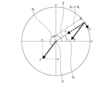
- 1 is a diagram illustrating an example of a relationship between a force that rotates a shaft and its radial and circumferential components.
- FIG. 1 is a diagram illustrating an example of a relationship between a force that rotates a shaft and its radial and circumferential components.
- FIG. 1 is a diagram illustrating an example of a relationship between a force that rotates a shaft and its radial and circumferential components.
- FIG. 1 is a diagram illustrating an example of a relationship between a force that rotates a shaft and its radial and circumferential components.
- FIG. 1 is a diagram illustrating an example of a relationship between a force that rotates a shaft and its radial and circumferential components.
- 1 is a perspective view of a holder, a strain sensor, and a plate portion of a sensor device according to an embodiment that is an example of the present invention.
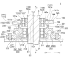
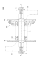
- 1 is a cross-sectional view of a sensor device according to an embodiment that is one example of the present invention (however, a calculation circuit is omitted).
- 11 is a cross-sectional view showing another example of a holder included in a sensor device according to an embodiment that is one example of the present invention.
- FIG. 13 is a cross-sectional view showing still another example of a holder included in a sensor device according to an embodiment which is one example of the present invention.
- FIG. 11 is a cross-sectional view showing still another example of a holder included in a sensor device according to an embodiment which is one example of the present invention.
- FIG. 13 is a plan view showing still another example of a holder included in a sensor device according to an embodiment that is one example of the present invention.
- FIG. 12 is a cross-sectional view showing still another example of the holder included in the sensor device according to the embodiment which is one example of the present invention, and corresponds to the AA cross section in FIG. 11 .
- 13 is a plan view showing still another example of a holder included in a sensor device according to an embodiment that is one example of the present invention.
- FIG. 14 is a cross-sectional view showing still another example of the holder included in the sensor device according to the embodiment which is one example of the present invention, and corresponds to the cross-section BB in FIG. 13 .
- FIG. 11 is a perspective view showing still another example of a holder included in a sensor device according to an embodiment which is one example of the present invention.
- 13 is a plan view showing still another example of a holder included in a sensor device according to an embodiment that is one example of the present invention.
- FIG. FIG. 1 is a schematic diagram showing an application example of a sensor device according to an embodiment that is an example of the present invention.
- 11A and 11B are schematic diagrams showing another application example of a sensor device according to an embodiment that is one example of the present invention.
- the direction of arrow a along the axis X (the central axis of the shaft S) is referred to as the upper side or one side in the axial direction.
- the direction of arrow b along the axis X is referred to as the lower side or the other side in the axial direction.
- the direction of arrows ab is referred to as the up-down direction or axial direction (axial direction of the first bearing 202, 602).
- the up-down direction does not necessarily coincide with the vertical direction.
- the direction of arrows cd is referred to as the radial direction (radial direction of the first bearing 202, 602)
- the direction of arrow c away from the axis X is referred to as the outer side or one side in the radial direction
- the direction of arrow d approaching the axis X is referred to as the inner side or the other side in the radial direction.
- the direction along the tangent of the circle around the axis X (direction perpendicular to the radial direction) is referred to as the tangential direction
- the direction rotating around the axis X is referred to as the circumferential direction (circumferential direction of the first bearing 202, 602).
- FIG. 1 is a block diagram showing a schematic configuration of a sensor device 1 according to the present embodiment.
- the sensor device 1 includes a first bearing 202, a shaft S having a portion supported by the first bearing 202, a plurality of (four in the present embodiment) strain sensors 203, a sensor 100 for detecting information on the position (rotation angle) of the shaft S in the circumferential direction of the first bearing 202, and an arithmetic circuit 10.
- FIGS. 2 to 5 are diagrams showing various examples of the relationship between a force F that rotates (or is applied to rotate) the shaft S, and its radial component Fr and circumferential component Ft .
- the "force that rotates the shaft” is referred to as the "force applied to rotate the shaft”.
- the "force that rotates the shaft” is a vector, and may include a force component that does not easily contribute to rotating the shaft.
- the plurality of strain sensors 203 are arranged so as to detect components x 1 and y 1 in two orthogonal directions among information of a radial force F' acting on the shaft S.
- the force F' is a force acting at the position of the shaft S through a member 3 when a force F is applied to a member 3 connected to the shaft S (for example, a crank different from the shaft S, or a member such as a pedal connected to the shaft via a crank) at a position away from the shaft S.
- x 1 is a component of F' in the direction along the x axis of FIGS. 2 to 5
- y 1 is a component of F' in the direction along the y axis of FIGS. 2 to 5.
- x 1 and y 1 may be positive or negative.
- the specific arrangement and configuration of the plurality of strain sensors 203 will be described later.
- the plurality of strain sensors 203 output information corresponding to x 1 and y 1 as a signal.
- the output signal is input to the arithmetic circuit 10.
- Fig. 1 two of the multiple (four) strain sensors 203 are shown outputting information on x1 as a signal, and the other two are shown outputting information on y1 as a signal, but in reality, the strains detected by each of the multiple strain sensors 203 do not necessarily correspond to only one of x1 or y1 .
- the arithmetic circuit 10 to which the strain information detected by each of the multiple strain sensors 203 is inputted as a signal, or another circuit (not shown) arbitrarily arranged on the signal path between the multiple strain sensors 203 and the arithmetic circuit 10 may be configured to integrate the strain information detected by each of the multiple strain sensors 203 and calculate x1 and y1 .
- the sensor 100 detects information on the position (rotation angle) of the shaft S in the circumferential direction. A specific configuration of the sensor 100 will be described later.
- the sensor 100 outputs information on the rotation angle ⁇ a of the shaft S with respect to a predetermined angle in the circumferential direction as a signal.
- the rotation angle ⁇ a indicates how much the shaft S has rotated counterclockwise with respect to the positive direction of the x-axis in Figs. 2 to 5, and is 0 ⁇ a ⁇ 2 ⁇ .
- the output signal is input to the arithmetic circuit 10.
- the arithmetic circuit 10 or another circuit (not shown) arbitrarily arranged on the signal path between the sensor 100 and the arithmetic circuit 10 may be configured to calculate the rotation angle ⁇ a based on the signal output from the sensor 100.
- the arithmetic circuit 10 is a program processing device (e.g., a microcontroller) having a configuration in which a processor such as a CPU, various storage devices such as RAM and ROM, and peripheral circuits such as a counter (timer), an A/D conversion circuit, a D/A conversion circuit, a clock generation circuit, and an input/output I/F circuit are connected to each other via a bus or dedicated lines.
- a processor such as a CPU
- various storage devices such as RAM and ROM
- peripheral circuits such as a counter (timer), an A/D conversion circuit, a D/A conversion circuit, a clock generation circuit, and an input/output I/F circuit are connected to each other via a bus or dedicated lines.
- the arithmetic circuit 10 has, for example, a memory unit 11, an angle calculation unit 12, a force information calculation unit 13, a first component calculation unit 14, and a second component calculation unit 15.
- the memory unit 11, the angle calculation unit 12, the force information calculation unit 13, the first component calculation unit 14, and the second component calculation unit 15 are realized, for example, in a program processing device serving as the arithmetic circuit 10, by a processor executing various arithmetic processes according to programs stored in memory and controlling peripheral circuits such as counters and A/D conversion circuits. Note that the arithmetic circuit 10 may have other functions.
- the arithmetic circuit 10 receives signals output from the multiple strain sensors 203 and the sensor 100.
- the memory unit 11 stores the input values of x 1 , y 1 and ⁇ a .
- the angle calculation unit 12 refers to the values of x 1 and y 1 stored in the memory unit 11, calculates the angle ⁇ b of the direction of the force F relative to a predetermined angle, and stores the value of ⁇ b in the memory unit 11.
- ⁇ b is the angle between the positive direction of the x axis in Figures 2 to 5 and the direction of the force F, and 0 ⁇ b ⁇ 2 ⁇ .
- ⁇ b can be calculated, for example, using the following formula (1).
- the force information calculation unit 13 refers to the values of x1 and y1 stored in the memory unit 11 and the value of the distance r from the position where the force F is applied to the shaft S, calculates the magnitude f of the force F, and stores the value (information) of f in the memory unit 11.
- the force F is the force applied to the pedal
- r is the distance (length of the crank) from the pedal to the shaft S (crankshaft).
- f can be calculated, for example, using the following formula (2).
- the method of calculating f is not limited to using formula (2).
- the first component calculation unit 14 refers to the values of f, ⁇ a , and ⁇ b stored in the storage unit 11, calculates the magnitude f r of the radial component F r of the force F, and stores the value (information) of f r in the storage unit 11.
- f r can be calculated using, for example, the following formula (3). However, the method of calculating f r is not limited to using formula (3).
- the second component calculation unit 15 refers to the values of f, ⁇ a , and ⁇ b stored in the storage unit 11, calculates the magnitude ft of the circumferential component Ft of the force F, and stores the value (information) of ft in the storage unit 11.
- ft can be calculated using, for example, the following formula (4). However, the method of calculating ft is not limited to using formula (4).
- the angle between the force F and the component Fr is ⁇ a - ⁇ b , but in the example of Fig. 4, the angle between the force F and the component Fr is 2 ⁇ - ⁇ b + ⁇ a , and in the example of Fig. 5, the angle between the force F and the component Fr is ⁇ b - ⁇ - ⁇ a .
- the above-mentioned method of calculating the magnitude f r of the radial component F r and the magnitude f t of the circumferential component F t of the force F is merely an example, and any calculation method may be used as long as it can obtain correct values or approximate values.
- the values (information) obtained by calculating the magnitude f r of the radial component F r and the magnitude f t of the circumferential component F t of the force F do not necessarily need to be strictly correct values, and may include errors within a range that does not interfere with actual use.
- Figure 6 is a perspective view showing the holder 201, strain sensor 203, and part of the sensor 100 of the sensor device 1.
- Figure 7 is a cross-sectional view of the sensor device 1 (however, the arithmetic circuit 10 is not shown).
- the sensor device 1 includes a sensor 100 that detects position information (rotation angle) of the shaft S, and a torque sensor 200.
- the sensor 100 includes a second bearing 101 having an inner circumferential surface 101a and an outer circumferential surface 101b, and a strain gauge 102 attached to the outer circumferential surface 101b of the second bearing 101 via a plate portion 141.
- the torque sensor 200 includes a first bearing 202 and multiple (four in this embodiment) strain sensors 203.
- the first bearing 202 is a ball bearing having an inner ring 202i, an outer ring 202o, and rolling elements.
- the second bearing 101 is a ball bearing having an inner ring 101i, an outer ring 101o, and rolling elements. Note that the first bearing 202 and the second bearing 101 are not limited to ball bearings, and may be various other bearings, such as sleeve bearings.
- the second bearing 101 is disposed on one side of the first bearing 202 (in the direction of arrow a) with a gap therebetween.
- the shaft S has a portion S1 supported by the first bearing 202 and a portion S2 supported by the second bearing 101.
- the holder 201 has a generally square cylindrical shape in a plan view, and has a retaining portion 210 and an outer peripheral member 220.
- the retaining portion 210 is a cylindrical member that extends in the axial direction and has a cylindrical inner peripheral surface 210a around the axis X.
- the retaining portion 210 is a member that retains the first bearing 202.
- the outer peripheral member 220 is a member that is disposed on one side of the retaining portion 210 in the radial direction (in the direction of the arrow c).
- the dimensions of the holding part 210 in the axial direction are the same as the dimensions of the outer peripheral member 220.
- the end face of the holding part 210 on one side in the axial direction (arrow a direction) and the end face on the other side in the axial direction (arrow b direction) are on the same plane as the end face of the outer peripheral member 220 on one side in the axial direction (arrow a direction) and the end face on the other side in the axial direction (arrow b direction).
- connection parts 230 At the end of one side in the radial direction (arrow c direction) and one side in the axial direction (arrow a direction) of the holding part 210, four connection parts 230 having a substantially rectangular shape in a plan view radially protrude from the holding part 210 to one side in the radial direction (arrow c direction).
- the four connection parts 230 are arranged at positions that overlap when rotated 90° around the axis X in rotational symmetry (hereinafter also referred to as "four-fold symmetry" in this specification).
- the connection parts 230 connect the holding part 210 to the deformable surface 222 described later.
- a flexure body 221 that is rectangular in plan view and generally L-shaped in side view is connected.
- the flexure body 221 is a deformation portion that deforms when subjected to stress, and undergoes elastic or plastic deformation when subjected to stress.
- the four flexure bodies 221 form the outer peripheral member 220 in this embodiment. Since all four flexure bodies 221 have the same configuration, only one flexure body 221 will be described in detail below, and detailed descriptions of the other flexure bodies 221 will be omitted.
- the strain body 221 (outer peripheral member 220) has a deformable surface 222 extending in the axial direction.
- the holder 201 has a gap 240 (described later) between the deformable surface 222 and the retaining portion 210 located on the first bearing 202 side of the deformable surface 222. Due to the shape of the gap 240, the deformable surface 222 has a thinner wall thickness (radial thickness) than other parts of the strain body 221 (outer peripheral member 220), making it easier for deformation accompanied by strain to occur.
- the strain body 221 (outer peripheral member 220) faces the retaining portion 210 via a gap 240 extending in the tangential or circumferential direction.
- the gap 240 includes a through hole (hole portion) 241 having a circular or approximately circular cross section, and a slit 242 connected to the through hole 241.
- the slit 242 is connected to the through hole 241 at a position on the other side in the axial direction (arrow b direction) and closer to the other side in the radial direction (arrow d direction).
- the width (radial width) of the slit 242 is narrower than the outer shape (diameter) of the through hole 241.
- a recess is formed on the surface of the strain body 221 (outer peripheral member 220) on the other radial side (arrow d direction) that is recessed on one side in the radial direction (arrow c direction), a recess is formed on the surface of the connection part 230 on the other axial side (arrow b direction) that is recessed on one side in the axial direction (arrow a direction), and a recess is formed on the surface of the holding part 210 on the one radial side (arrow c direction) that is recessed on the other radial side (arrow d direction).
- each strain body 221 has a deformable surface 222
- the holder 201 of the torque sensor 200 has a plurality of deformable surfaces 222 (four in this embodiment) as a whole.
- the plurality of deformable surfaces 222 are arranged in a line at positions that are four-fold symmetric (rotationally symmetric) in the circumferential direction ( Figure 6).
- a strain sensor 203 is attached to one side (arrow c direction) in the radial direction of the deformable surface 222.
- a strain sensor 203 By attaching a strain sensor 203 to each of the multiple deformable surfaces 222, multiple (four in this embodiment) strain sensors 203 are attached to the torque sensor 200.
- the directions of strain detected by each strain sensor 203 are different from each other.
- the deformable surface 222 and the strain sensor 203 each extend along a plane parallel to the axial direction.
- the strain sensor 203 is attached so that it can detect the strain of the deformable surface 222.
- the strain sensor 203 when the strain sensor 203 is a strain gauge, it is attached to the deformable surface 222 so that the grid direction (typically the longitudinal direction of the strain gauge) is the axial direction (see arrow D1 in Figure 6).
- the grid direction of the multiple strain sensors 203 is not limited to the axial direction, and may be oblique to the axial direction.
- the grids of two opposing strain sensors 203 may be oriented in the axial direction, and the grids of the other two opposing strain sensors 203 may be oriented in the circumferential direction.
- the grids of the two opposing strain sensors 203 may be oriented in a direction oblique to the axial direction (first direction), and the grids of the other two opposing strain sensors 203 may be oriented in a direction oblique to the axial direction and in a different direction (second direction) such as a direction intersecting the first direction.
- the strain sensor 203 is a strain gauge
- the strain of the deformable surface 222 is detected as a change in resistance value.
- the strain sensor 203 is not limited to a strain gauge, and may be various other sensors such as a piezoelectric element.
- a fixed portion 223 that is connected to the external device 2 is disposed on one side (arrow c direction) of the deformable surface 222 of the strain body 221 in the radial direction.
- the fixed portion 223 is a rectangular plate-like portion that extends from the end of the other side (arrow b direction) in the axial direction of the deformable surface 222 toward one side (arrow c direction) in the radial direction.
- a circular through hole (hole portion) 223h is formed near the center of the fixed portion 223.
- the strain body 221 is fixed to the external device 2 via a spacer 205 by a bolt 204 inserted into the through hole 223h. As a result, the entire holder 201 is fixed to the external device 2.
- the first bearing 202 is disposed on the other side (arrow d direction) of the holding portion 210 of the holder 201.
- the first bearing 202 is held by the holding portion 210 of the holder 201.
- the inner ring 202i of the first bearing 202 is bonded or pressed into the outer peripheral surface (one side surface in the radial direction) of the portion S1 of the cylindrical shaft S that is supported by the first bearing 202.
- the inner ring 202i of the first bearing 202 is fixed to the shaft S.
- the outer ring 202o of the first bearing 202 is pressed into the inner peripheral surface 210a of the holding portion 210 of the holder 201.
- the first bearing 202 supports the shaft S rotatably relative to the holder 201.
- the end of the shaft S on the other side (arrow b direction) in the axial direction protrudes from the through hole (hole portion) 21 of the external device 2 to the outside of the external device 2.
- the holder 201 has an annular contact portion 211 that protrudes radially to the other side (arrow d direction) at the end on the other side in the axial direction (arrow b direction).
- the contact portion 211 protrudes radially to the other side (arrow d direction) from the holding portion 210 of the holder 201.
- the contact portion 211 is in contact with the end face of the outer ring 202o of the first bearing 202 on the other side in the axial direction (arrow b direction). As a result, the contact portion 211 supports the first bearing 202 in a state where downward movement in the axial direction is restricted.
- a recess 212 having a semicircular or approximately semicircular cross section is formed near the end on the other axial side (arrow b direction) of the inner circumferential surface 210a of the retaining portion 210, recessed to one radial side (arrow c direction).
- the recess 212 is formed in an annular shape around the axis X on one axial side (arrow a direction) of the contact portion 211.
- the end on the other axial side (arrow b direction) of the concave surface of the recess 212 smoothly connects to the end face of the contact portion 211 on one axial side (arrow a direction).
- the shaft S is a crankshaft to which the crank (crank arm) and pedal are connected.
- crank crank arm
- pedal When one pedal is stepped on, a force acts on the shaft S on that pedal side to tilt vertically downward, causing the first bearing 202 to move radially and pressing a part of the holder 201 towards one side in the radial direction (in the direction of arrow c).
- stress tends to concentrate on the deformable surface 222 of the strain body 221, causing deformation accompanied by distortion of the deformable surface 222.
- strains corresponding to inclinations of the shaft S in all directions can be detected.
- the four strain bodies 221 are located at positions that are four-fold symmetrical about the axis X, so that strains in all directions can be detected more accurately.
- the amount of deformation of the deformable surfaces 222 is detected by the plurality of strain sensors 203 as information on the force F' acting on the shaft S. Based on the detected strain, information on the components x1 and y1 in two orthogonal directions of the radial force F' acting on the shaft S can be calculated.
- the torque sensor 200 has a simple configuration including a holder 201, a first bearing 202, and a strain sensor 203. Since detection coils and other components required when using a magnetostrictive sensor are not arranged around the shaft S, the device can be made more compact. In addition, since no processing such as attaching a magnetic layer to the shaft S is required, manufacturing is easy.
- the strain body 221 (outer peripheral member 220) faces the retaining portion 210 in the radial direction with a gap 240 between them. This allows the deformable surface 222 of the strain body 221 to deform easily in the torque sensor 200, enabling stress to be detected with high sensitivity.
- the recess 212 is formed, so that the thickness of the retaining portion 210 near the end on the other axial side (arrow b direction) is thin, making it easier for the contact portion 211 to elastically deform toward the other axial side (arrow b direction).
- the contact portion 211 can elastically deform to absorb the effects of the preload. Therefore, in the torque sensor 200, the preload on the first bearing 202 is prevented from appearing as a strain on the deformable surface 222, and the strain sensor 203 can detect stress with high sensitivity.
- the portion of the sensor device 1 on one side of the torque sensor 200 in the axial direction (in the direction of arrow a) (sensor 100 that detects position information (rotation angle) of shaft S) will be described.
- the sensor 100 has a second bearing 101 having an inner circumferential surface 101a and an outer circumferential surface 101b, and a strain gauge 102 attached to the outer circumferential surface 101b of the second bearing 101 via a holder 201.
- an eccentric member 103 having an axial dimension that is the same or approximately the same as that of the second bearing 101 is disposed.
- the eccentric member 103 causes the second bearing 101 and the shaft S to be eccentric relative to each other. In other words, the eccentric member 103 causes the second bearing 101 to be eccentric with respect to the shaft S.
- the eccentric member 103 is a cylindrical member extending in the axial direction, and has a cylindrical through hole (hole portion) with an inner diameter that is the same or approximately the same as the outer diameter (diameter) of the shaft S.
- the eccentric member 103 is an annular member.
- the central axis of the outer peripheral surface (surface on one side in the radial direction) does not coincide with the central axis of the inner peripheral surface (surface on the other side in the radial direction). Therefore, the eccentric member 103 has a portion 103a where the radial thickness is maximum (hereinafter referred to as the maximum thickness portion) and a portion 103b where the radial thickness is minimum (hereinafter referred to as the minimum thickness portion).
- the shaft S is bonded or pressed into the inner peripheral surface (the radially inner surface) of the eccentric member 103 at the portion S2 supported by the second bearing 101. This allows the shaft S to be fixed integrally with the eccentric member 103.
- the inner ring 101i of the second bearing 101 is bonded or pressed into the outer peripheral surface (the radially outer surface) of the eccentric member 103. This allows the inner ring 101i of the second bearing 101 to be fixed to the eccentric member 103.
- the axis X which is the central axis of the shaft S, is offset from the central axis Y of the eccentric member 103 and the second bearing 101, so the second bearing 101 and the shaft S are in an eccentric positional relationship with each other.
- plate parts 141 rise up toward one side in the axial direction (arrow a direction) on the end face of one side in the axial direction of the holding part 210 of the holder 201.
- the four plate parts 141 are arranged in positions that are four-fold symmetrical around the axis X on one side (arrow c direction) of the second bearing 101 in the radial direction.
- the four plate parts 141 are arranged in positions corresponding to the four strain bodies 221.
- Each plate part 141 is in contact with the outer peripheral surface 101b of the second bearing 101 via the tip part 145a on the other side in the radial direction (arrow d direction) of the transmission part 145 described later.
- the second bearing 101 is arranged on one side (arrow a direction) of the end face on one side in the axial direction (arrow a direction) of the holding part 210 in the axial direction.
- Each plate portion 141 holds a strain gauge 102. That is, the sensor 100 has a total of four strain gauges 102, in a clockwise direction in a plan view: a first strain gauge 102a held by the first plate portion 141a, a second strain gauge 102b held by the second plate portion 141b, a third strain gauge 102c held by the third plate portion 141c, and a fourth strain gauge 102d held by the fourth plate portion 141d.
- Two adjacent strain gauges 102 in the circumferential direction are arranged in positions that are symmetrical with respect to a plane including the axis X.
- the angle between the direction from the axis X toward the first strain gauge 102a and the direction from the axis X toward the second strain gauge 102b is 90°. However, this angle does not have to be 90°. Since all four plate portions 141 have the same configuration, only one plate portion 141 will be described in detail below, and detailed descriptions of the other plate portions 141 will be omitted unless necessary.
- a recess 144 having a semicircular cross section extending in the tangential or circumferential direction is formed on the surface on the other side (arrow d direction) of the plate portion 141.
- the recess 144 is formed near the end of the plate portion 141 on the other side in the axial direction (arrow b direction).
- the portion where the recess 144 is formed has a thin wall thickness, forming a deformation portion 142 capable of deformation accompanied by strain.
- the strain gauge 102 is attached to the surface on one side in the radial direction (arrow c direction) of the deformation portion 142.
- the deformation accompanied by strain of the deformation portion 142 can be detected as a change in the resistance value of the strain gauge 102.
- An opening 141h which is a circular hole penetrating in the radial direction, is formed in the center of the plate portion 141 in the tangential or circumferential direction and on one side in the axial direction (arrow a direction) of the recess 144.
- a transmission portion 145 having a pin-shaped outer shape is inserted into the opening 141h.
- the transmission part 145 is fixed to the opening 141h by adhesion or press fitting.
- the transmission part 145 has a pointed tip 145a.
- the transmission part 145 is arranged so that the tip 145a protrudes radially further to the other side (in the direction of arrow d) than the plate part 141.
- the outer peripheral surface 101b of the second bearing 101 is in point contact with the tip 145a of the transmission part 145. Therefore, the transmission part 145 can transmit the displacement of the second bearing 101 to the plate part 141 via the tip 145a.
- the thickest part 103a of the eccentric member 103 is located close to the third plate portion 141c, and the thinnest part 103b of the eccentric member 103 is located close to the first plate portion 141a. Therefore, the third plate portion 141c is pressed toward one side in the radial direction (in the direction of the arrow c) by the second bearing 101.
- the second plate portion 141b and the fourth plate portion 141d adjacent to the third plate portion 141c are also slightly pressed toward one side in the radial direction (in the direction of the arrow c) by the second bearing 101.
- the deformed portion 142 of the third plate portion 141c is deformed with the greatest distortion, and one axial side of the third plate portion 141c (the direction of arrow a) is warped toward one radial side (the direction of arrow c).
- the deformed portions 142 of the second plate portion 141b and the fourth plate portion 141d adjacent to the third plate portion 141c are in a state of slight distortion.
- the deformed portion 142 of the first plate portion 141a is in a state of least distortion or no distortion at all.
- the eccentric member 103 fixed to the shaft S also rotates, and accordingly, the central axis Y of the second bearing 101 also rotates around the axis X.
- the central axis Y of the second bearing 101 rotates clockwise in a plan view around the axis X.
- the central axis Y of the second bearing 101 rotates 90° clockwise in a plan view around the axis X from the state in FIG. 7, the deformed portion 142 of the fourth plate portion 141d transitions to a state in which it has been deformed with the greatest strain.
- signals output from the multiple strain sensors 203 and the sensor 100 are input to the arithmetic circuit 10, and the arithmetic circuit 10 calculates the magnitude f r of the radial component F r and the magnitude f t of the circumferential component F t of the information of the force F that rotates the shaft S. This allows the sensor device 1 to calculate the information of the force F that rotates the shaft S by dividing it into the radial component F r and the circumferential component F t .
- the force F applied to rotate the shaft S is the pedal force applied by the rider's foot to the pedal.
- the circumferential component of the pedal force F contributes to the rotation of the crank and the shaft S. In other words, it corresponds to the propulsive force of the rotation of the crank and the shaft S.
- the radial component of the pedal force F does not contribute much to the rotation of the crank and the shaft S. In other words, it corresponds to a loss force that does not contribute much to the rotation of the crank and the shaft S.
- the sensor device 1 can calculate the magnitude fr of the radial component Fr and the magnitude ft of the circumferential component Ft of the pedal force F, for example, by outputting this information from the calculation circuit 10 to a cycle computer, it is possible to encourage the rider to change to a more efficient pedaling style. Furthermore, when the sensor device 1 is used in an electrically assisted bicycle or the like, signals corresponding to the magnitude f r of the radial component Fr and the magnitude f t of the circumferential component Ft of the pedal force F information can be output to a motor drive unit, thereby making it possible to use the signal for control by the motor drive unit.
- the sensor device of the present invention has been described above with reference to preferred embodiments, the sensor device of the present invention is not limited to the configuration of the above embodiments.
- the sensor device 1 according to the above embodiments is described assuming that it is used on a bicycle, but the sensor device of the present invention is not limited to being used on a bicycle, and may be used on a moving body or a rotating device.
- the sensor device 1 according to the above embodiment can be designed to be compact overall because the sensor 100 and the torque sensor 200 are integrated into one structure.
- the sensor that detects information about the shaft position does not need to be integrated into the holder to which the multiple strain sensors are attached.
- the second bearing 101 and the shaft S are attached in an eccentric state with respect to each other by using an annular eccentric member 103.
- the second bearing 101 and the shaft S may be made eccentric with respect to each other by interposing a wedge-shaped member between them without using the annular eccentric member 103.
- the sensor 100 of the sensor device 1 detects the position information of the shaft S using the strain gauge 102, but in the sensor device of the present invention, the sensor that detects the position information of the shaft may be any type as long as it can detect the rotation angle of the shaft.
- the sensor that detects the position information of the shaft may be an optical sensor using a light-emitting element and a light-receiving element, or a magnetic sensor such as a Hall sensor.
- the sensor that detects the position information of the shaft does not have to be a sensor in the strict sense, and may be a device that can detect the position of the shaft based on the number of rotations of a roller or the like that rotates in contact with the shaft.
- the sensor that detects the position information of the shaft may be located near a holder to which multiple strain sensors are attached, or may be located at a distance.
- the sensor that detects the position information of the shaft may be located at a distance from the shaft.
- the sensor that detects the position information of the shaft may be located on the chain ring, sprocket, rear wheel, crank, or pedal of a bicycle.
- the sensor may be provided on the inside or side of the housing.
- the number of strain sensors attached to the holder in the sensor device of the present invention may be two, three, five or more, as long as the calculation circuit can ultimately calculate the magnitude of the radial and circumferential components of the force information applied to rotate the shaft. It is preferable that at least two of the multiple strain sensors are arranged with a 90° offset from each other in the circumferential direction, but the offset angle may be greater than 0° and less than 180°, may be 20° or more and 160° or less, may be 40° or more and 140° or less, may be 60° or more and 120° or less, or may be 80° or more and 100° or less.
- the configuration of the holder to which the multiple strain sensors are attached is not limited to the holder 201 of the torque sensor 200 of the sensor device 1 according to the above embodiment.
- the holder to which the multiple strain sensors are attached may have the modified configurations shown in Figures 8 to 16, or may have a further different configuration. Note that the sensor and calculation circuit that detects information on the position of the shaft S are omitted in Figures 8 to 16.
- Fig. 8 is a cross-sectional view showing a state in which the torque sensor 300 is attached to the shaft S and the external device 2.
- the torque sensor 300 has a similar configuration to the torque sensor 200, except that it includes a holder 301 instead of the holder 201.
- the holder 301 has a similar configuration to the holder 201, except that it includes a holding portion 310 instead of the holding portion 210 and has a gap 340 whose shape is different from the gap 240.
- members and parts having the same functions and configurations as the torque sensor 200 are denoted by the same reference numerals, and detailed description thereof will be omitted.
- the holder 301 has a generally square cylindrical shape in plan view, and has a holding portion 310 and an outer peripheral member 220.
- the holding portion 310 is a cylindrical member that extends in the axial direction and has a cylindrical inner peripheral surface 310a around the axis X.
- the holding portion 310 is a member that holds the first bearing 202.
- the outer peripheral member 220 is a member that is positioned radially outward of the holding portion 310.
- connection parts 330 which are generally rectangular in plan view, protrude radially from the end of the holding part 310 on one radial side (arrow c direction) and one axial side (arrow a direction) of the holding part 310 to one radial side (arrow c direction).
- the four connection parts 330 are arranged at positions that are four-fold symmetrical around the axis X.
- a strain body 221 is connected to each connection part 330.
- the strain body 221 (outer peripheral member 220) faces the retaining portion 210 via a gap 340 extending in the tangential or circumferential direction.
- the gap 340 includes a through hole (hole portion) 341 having a circular or approximately circular cross section, and a slit 342 that is connected to the other side in the axial direction of the through hole 341 (the direction of the arrow b) and has a width (radial width) narrower than the diameter of the through hole 341.
- the dimension of the slit 342 formed in the holder 301 is smaller than the dimension of the slit 242 formed in the holder 201 shown in FIG. 7.
- a recess is formed on the surface of the strain body 221 (outer peripheral member 220) on the other radial side (arrow d direction) that is recessed on one side in the radial direction (arrow c direction), a recess is formed on the surface of the connection part 330 on the other axial side (arrow b direction) that is recessed on one side in the axial direction (arrow a direction), and a recess is formed on the surface of the holding part 310 on the one radial side (arrow c direction) that is recessed on the other radial side (arrow d direction).
- the holder 301 has an annular contact portion 311 that protrudes radially to the other side (arrow d direction) from the end portion on the other axial side (arrow b direction) of the holding portion 310 of the holder 301.
- the contact portion 311 protrudes radially to the other side (arrow d direction) from the end portion on the other axial side (arrow b direction) of the holding portion 310 of the holder 301.
- the contact portion 311 is in contact with the end face on the other axial side (arrow b direction) of the outer ring 202o of the first bearing 202. As a result, the contact portion 311 supports the first bearing 202 in a state where downward movement in the axial direction is restricted.
- the gap 340 formed in the holder 301 shown in FIG. 8 has a simpler shape than the gap 240 formed in the holder 201 shown in FIG. 7. Furthermore, the holder 301 shown in FIG. 8 does not have anything corresponding to the recess 212 formed in the holder 201 shown in FIG. 7. Therefore, the holder 301 shown in FIG. 8 is easier to manufacture than the holder 201 shown in FIG. 7.
- Fig. 9 is a cross-sectional view showing a state in which the torque sensor 400 is attached to the shaft S and the external device 2.
- the torque sensor 400 has a similar configuration to the torque sensor 300 of the first modified example, except that the torque sensor 400 includes a holder 401 instead of the holder 301.
- members and parts having the same functions and configurations as the torque sensor 300 of the first modified example are denoted by the same reference numerals, and detailed description thereof will be omitted.
- the holder 401 has a generally square cylindrical shape in plan view, and includes a holding portion 410 and an outer peripheral member 420.
- the holding portion 410 is a cylindrical member that extends in the axial direction and has a cylindrical inner peripheral surface 410a around the axis X.
- the outer peripheral member 420 is a member that is positioned radially to one side of the holding portion 410 (in the direction of the arrow c).
- the dimensions of the holding portion 410 are smaller than the dimensions of the outer peripheral member 420.
- the end face of one side (arrow a direction) of the holding portion 410 and the end face of one side (arrow a direction) of the outer peripheral member 420 are on the same plane.
- four connection portions 430 that are approximately rectangular in plan view protrude radially from the holding portion 410 to one radial side (arrow c direction).
- the four connection portions 430 are arranged at positions that are four-fold symmetric around the axis X.
- connection part 430 is connected to a flexure body 421 that is rectangular in plan view and generally inverted T-shaped in side view.
- the flexure body 421 is a deformation part that deforms when subjected to stress, and undergoes elastic or plastic deformation when subjected to stress.
- the four flexure bodies 421 form the outer peripheral member 420 in this embodiment. Since all four flexure bodies 421 have the same configuration, only one flexure body 421 will be described in detail below, and detailed descriptions of the other flexure bodies 421 will be omitted.
- the strain body 421 (outer peripheral member 420) has a deformable surface 422 extending in the axial direction.
- the holder 401 has a gap 440 (described later) between the deformable surface 422 and a retaining portion 410 located on the first bearing 202 side of the deformable surface 422. Due to the shape of the gap 440, the deformable surface 422 has a thinner wall thickness (radial thickness) than other parts of the strain body 421 (outer peripheral member 420), making it easier for deformation accompanied by strain to occur.
- the gap 440 includes a first through hole (hole portion) 441 having a circular or approximately circular cross section, a second through hole (hole portion) 442 that is connected to the other axial side (arrow b direction) of the first through hole 441 and has a diameter equal to or slightly smaller than that of the first through hole 441, and a slit 443 that extends from the end of the other axial side (arrow b direction) of the second through hole 442 toward the other radial side (arrow d direction) to the first bearing 202.
- a recess is formed on the surface of the strain body 421 (outer peripheral member 420) on the other radial side (arrow d direction) that is recessed on one side in the radial direction (arrow c direction), a recess is formed on the surface of the connection part 430 on the other axial side (arrow b direction) that is recessed on one side in the axial direction (arrow a direction), and a recess is formed on the surface of the holding part 410 on the one radial side (arrow c direction) that is recessed on the other radial side (arrow d direction).
- each strain body 421 has a deformable surface 422
- the holder 401 of the torque sensor 400 has a plurality of deformable surfaces 422 (four in this modified example) as a whole.
- the plurality of deformable surfaces 422 are arranged in a line at positions that are four-fold symmetrical in the circumferential direction.
- a strain sensor 203 is attached to one radial side (arrow c direction) of the deformable surface 422.
- multiple strain sensors 203 are attached to the torque sensor 400.
- the deformable surfaces 422 and the strain sensors 203 each extend along a plane parallel to the axial direction.
- the strain sensor 203 is attached so as to detect the strain of the deformable surface 422. Therefore, when the strain sensor 203 is a strain gauge, it is attached to the deformable surface 422 so that the grid direction (typically the longitudinal direction of the strain gauge) is the axial direction.
- the strain sensor 203 is a strain gauge, the strain of the deformable surface 422 is detected as a change in resistance value.
- the directions of strain detected by each strain sensor 203 are different from each other.
- the holder 401 has a plate-shaped contact portion 424 that protrudes from the end of the other side (arrow b direction) in the axial direction to the other side in the radial direction (arrow d direction).
- the contact portion 424 protrudes from the end of the other side (arrow b direction) in the axial direction of the strain body 421 (outer peripheral member 420) of the holder 401 to the other side in the radial direction (arrow d direction).
- the contact portion 424 faces the holding portion 410 via a slit 443.
- the tangential or circumferential dimension of the contact portion 424 is the same as the tangential or circumferential dimension of the strain body 421.
- the contact portion 424 may be formed in an annular shape around the axis X. In the axial direction, the contact portion 424 contacts the end face of the other side (arrow b direction) of the outer ring 202o of the first bearing 202. As a result, the contact portion 424 supports the first bearing 202 while restricting its downward movement in the axial direction.
- Fig. 10 is a cross-sectional view showing a state in which the torque sensor 500 is attached to the shaft S and the external device 2.
- the torque sensor 500 has a similar configuration to the torque sensor 300 of the first modified example, except that the torque sensor 500 includes a holder 501 instead of the holder 301.
- the holder 501 has a similar configuration to the holder 301 of the first modified example, except that the holder 501 includes a holding portion 510 instead of the holding portion 310, and the gap 340 is a gap 540 with a different shape.
- members and parts having the same functions and configurations as the torque sensor 300 of the first modified example are denoted by the same reference numerals, and detailed description thereof will be omitted.
- the holder 501 has a generally square cylindrical shape in plan view, and includes a holding portion 510 and an outer peripheral member 220.
- the holding portion 510 is a cylindrical member that extends in the axial direction and has a cylindrical inner peripheral surface 510a around the axis X.
- the dimensions of the holding portion 510 are smaller than the dimensions of the outer peripheral member 220.
- the end face of one side (arrow a direction) of the holding portion 510 and the end face of one side (arrow a direction) of the outer peripheral member 220 are on the same plane.
- connection portions 530 that are generally rectangular in plan view radially protrude from the holding portion 510 to one side in the radial direction (arrow c direction).
- the four connection portions 530 are arranged at positions that are four-fold symmetric around the axis X.
- a strain body 221 is connected to each connection portion 530.
- the gap 540 includes a through hole (hole portion) 541 having a circular or approximately circular cross section, and a slit 542 that is connected to the other axial side (arrow b direction) of the through hole 541 and has a width (radial dimension) narrower than the diameter of the through hole 541.
- a recess is formed on the surface of the strain body 221 (outer peripheral member 220) on the other radial side (arrow d direction) that is recessed on one side in the radial direction (arrow c direction), a recess is formed on the surface of the connection part 530 on the other axial side (arrow b direction) that is recessed on one side in the axial direction (arrow a direction), and a recess is formed on the surface of the holding part 510 on the one radial side (arrow c direction) that is recessed on the other radial side (arrow d direction).
- the external device 2 is fixed with a protruding portion 22 formed in an annular shape around the axis X, which protrudes toward one side in the axial direction (in the direction of the arrow a) toward the first bearing 202.
- the protruding portion 22 may be a plurality of convex portions arranged on a circumference around the axis X.
- the protruding portion 22 contacts the end face on the other side (in the direction of the arrow b) of the first bearing 202.
- the protruding portion 22 supports the first bearing 202 in a state in which downward movement in the axial direction is restricted. More specifically, in the axial direction, the protruding portion 22 supports the first bearing 202 by contacting the end face on the other side (in the direction of the arrow b) of the outer ring 202o.
- the protrusion 22 supports the first bearing 202 in the axial direction, so that the effect of the axial preload on the first bearing 202 can be prevented from appearing as distortion of the deformable surface 222.
- Fig. 11 is a plan view of the holder 601 and the strain sensor 603.
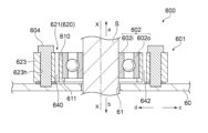
- Fig. 12 is a cross-sectional view showing a cross section corresponding to the A-A cross section in Fig. 11 in a state in which the torque sensor 600 is attached to the shaft S and the external device 60.
- the torque sensor 600 has a holder 601, a first bearing 602, and a strain sensor 603.
- the first bearing 602 is a ball bearing having an inner ring 602i, an outer ring 602o, and rolling elements.
- the first bearing 602 is not limited to a ball bearing, and may be, for example, a sleeve bearing or any other type of first bearing.
- the holder 601 has a generally square cylindrical shape in plan view, and has a holding portion 610 and an outer peripheral member 620.
- the holding portion 610 is a cylindrical member that extends in the axial direction and has a cylindrical inner peripheral surface 610a around the axis X.
- the outer peripheral member 620 is a member that is positioned radially to one side of the holding portion 610 (in the direction of the arrow c).
- the dimensions of the retaining portion 610 are the same as the dimensions of the outer peripheral member 620.
- the end face on one side (arrow a direction) and the end face on the other side (arrow b direction) of the retaining portion 610 are on the same plane as the end face on one side (arrow a direction) and the end face on the other side (arrow b direction) of the outer peripheral member 620, respectively.
- strain bodies 621 are connected to one side (arrow c direction) of the holding part 610 so as to be mirror symmetrical with respect to a plane including the axis X.
- the strain body 621 is a deformation part that deforms when subjected to stress, and undergoes elastic or plastic deformation when subjected to stress.
- the strain body 621 is a substantially rectangular parallelepiped with the tangential or circumferential direction as the longitudinal direction, and is notched in an arc shape along the outer shape of the holding part 610 to about half the radial dimension at the center of the longitudinal direction.
- the two strain bodies 621 form the outer peripheral member 620 in this embodiment. Since the two strain bodies 621 have the same configuration, only one strain body 621 will be described in detail below, and a detailed description of the other strain body 621 will be omitted.
- the flexure body 621 has two slits 642 that extend tangentially or circumferentially from near the connection with the retaining part 610 on the surface facing the retaining part 610 to the through holes 641.
- the width of the slits 642 is narrower than the diameter of the through holes 641.
- the through holes 641 and the slits 642 form a gap 640.
- the flexure body 621 (outer peripheral member 620) has a deformed portion 622. Of the portion of the flexure body 621 that extends along a plane perpendicular to the radial direction, the region near the through hole 641 forms the deformed portion 622. In the radial direction, the deformed portion 622 and the retaining portion 610 face each other across a gap 640.
- the deformed portion 622 has a radially recessed portion (part of the through hole 641) on the surface facing the retaining portion 610. Due to the presence of the through hole 641, the deformed portion 622 is thinner than other portions of the flexure body 621 (outer peripheral member 620), making it easier for deformation accompanied by strain to occur.
- the torque sensor 600 has multiple (four in this modified example) deformation portions 622 as a whole, since each of the strain bodies 621 has a deformation portion 622.
- the multiple deformation portions 622 are arranged side by side on one side (arrow c direction) of the holder 601 (one side in the radial direction from the holding portion 610 (arrow c direction)).
- Two strain sensors 603 are attached to the surface (deformable surface) of each of the strain bodies 621, which is opposite to the side connected to the holding part 610 and extends in the axial and tangential or circumferential directions.
- the strain sensor 603 is attached to the deformation part 622 of the strain body 621.
- the deformation part 622 and the strain sensor 603 extend along a plane extending in the axial direction and the longitudinal direction of the strain body 621.
- the strain sensor 603 is attached so as to detect the strain of the deformation part 622 in a direction along a plane perpendicular to the axial direction.
- the strain sensor 603 when the strain sensor 603 is a strain gauge, it is attached to the deformation part 622 so that the orientation of the grid (gauge) (typically the longitudinal direction of the strain gauge) is along the longitudinal direction of the strain body 621.
- the strain sensor 603 is a strain gauge, the strain of the deformation part 622 is detected as a change in resistance value.
- the strain sensor 603 is not limited to a strain gauge, but may be a variety of other sensors, such as a piezoelectric element.
- the portions of the flexure body 621 on both ends of the deformed portion 622 in the longitudinal direction form fixed portions 623 that are connected to the external device 60.
- a through hole (hole portion) 623h that is circular in plan view and penetrates in the axial direction is formed near the center of the fixed portion 623.
- the flexure body 621 is fixed to the external device 60 via a spacer 605 by a bolt 604 that is inserted into the through hole 623h from one side in the axial direction (the direction of the arrow a). In this way, the holder 601 is fixed to the external device 60.
- the first bearing 602 is disposed on the other side (arrow d direction) of the holding portion 610 of the holder 601.
- the first bearing 602 is held by the holding portion 610 of the holder 601.
- the inner ring 602i of the first bearing 602 is bonded or pressed into the outer peripheral surface (one side surface in the radial direction) of the cylindrical shaft S.
- the outer ring 602o of the first bearing 602 is pressed into the inner peripheral surface 610a of the holding portion 610 of the holder 601.
- the first bearing 602 supports the shaft S rotatably relative to the holder 601.
- the end of the shaft S on the other side (arrow b direction) in the axial direction protrudes from the through hole 61 of the external device 60 to the outside of the external device 60.
- the holder 601 has an annular contact portion 611 that protrudes radially to the other side (arrow d direction) at the end on the other side in the axial direction (arrow b direction).
- the contact portion 611 protrudes radially to the other side (arrow d direction) from the end on the other side in the axial direction (arrow b direction) of the holding portion 610 of the holder 601.
- the contact portion 611 contacts the end face on the other side (arrow b direction) of the outer ring 602o of the first bearing 602.
- the contact portion 611 supports the first bearing 602 in a state where downward movement in the axial direction is restricted.
- the shaft S is a crankshaft to which the crank and pedals are connected.
- a force acts that tilts the pedal side of the shaft S vertically downward, causing the first bearing 602 to move radially and pressing a part of the holder 601 towards one side in the radial direction (in the direction of arrow c).
- stress tends to concentrate in the deformed portion 622 of the strain body 621, so that deformation accompanied by distortion occurs in the deformed portion 622. This deformation accompanied by distortion is detected by the strain sensor 603.
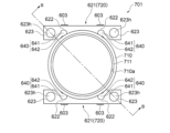
- Fig. 13 is a plan view of the holder 701 and the strain sensor 603.
- Fig. 14 is a cross-sectional view showing a cross section corresponding to the cross section B-B in Fig. 13 in a state in which the torque sensor 700 is attached to the shaft S and the external device 70.
- the torque sensor 700 has a similar configuration to the torque sensor 600 of the modified example 4, except that the torque sensor 700 includes the holder 701 instead of the holder 601.
- members and parts having the same functions and configurations as those of the modified example 4 are denoted by the same reference numerals, and detailed description thereof will be omitted.
- the torque sensor 700 has a holder 701, a first bearing 602, and a strain sensor 603.
- the holder 701 has a generally square cylindrical shape in plan view, and has a holding portion 710 and an outer peripheral member 720.
- the holding portion 710 is a cylindrical member that extends in the axial direction and has a cylindrical inner peripheral surface 710a around the axis X.
- the outer peripheral member 720 is a member that is disposed on one side (in the direction of the arrow c) of the holding portion 710 in the radial direction.
- the general configuration of the holder 701 is similar to that of the holder 601 of the torque sensor 600 of the fourth modification, but differs from that of the holder 601 of the torque sensor 600 of the fourth modification in that the axial dimension of the holding portion 710 is longer and that the holding portion 710 and the outer peripheral member 720 are connected so as to be shifted from each other in the axial direction.
- the dimensions of the holding portion 710 in the axial direction are greater than the dimensions of the outer peripheral member 720.
- the end face on one side (arrow a direction) and the end face on the other side (arrow b direction) of the holding portion 710 are disposed on one side (arrow a direction) of the end face on one side (arrow a direction) and the end face on the other side (arrow b direction) of the outer peripheral member 720, respectively.
- the end portion on one side (arrow a direction) in the axial direction of the outer peripheral member 720 is connected to the vicinity of the end portion on the other side (arrow b direction) in the axial direction of the holding portion 710.
- the holder 701 has an annular contact portion 711 that protrudes slightly from the center in the axial direction to one side (arrow a direction) and to the other side in the radial direction (arrow d direction).
- the contact portion 711 is provided on one side (arrow a direction) of the end of the outer peripheral member 720 on one side (arrow a direction).
- the contact portion 711 protrudes from near the center in the axial direction of the holding portion 710 of the holder 701 to the other side in the radial direction (arrow d direction).
- the contact portion 711 contacts the end face on the other side (arrow b direction) of the outer ring 602o of the first bearing 602.
- the contact portion 711 supports the first bearing 602 in a state where its downward movement in the axial direction is restricted.
- the outer peripheral member 720 is disposed on the other side of the external device 70 (outside the external device 70).
- a bolt 604 is inserted from the other side in the axial direction (in the direction of arrow b) into a through hole (hole portion) 623h formed in the fixing portion 623 of the strain generating body 621 of the outer peripheral member 720.
- the outer peripheral member 720 is disposed outside the external device 70, which simplifies the internal structure of the external device 70 and allows the device to be made smaller.
- Fig. 15 is a perspective view of the holder 801 and the strain sensor 803 of this modified example.
- the holder 801 is flat and has a holding portion 810 and an outer peripheral member 820.
- the holding portion 810 is a plate-like member that has a generally square shape in a plan view and has a cylindrical inner peripheral surface 810a around the axis X.
- the outer peripheral member 820 is a member that is disposed on one side of the holding portion 810 in the radial direction (in the direction of the arrow c).
- a flexure body 821 is connected to each of the two opposing outer peripheral surfaces (surfaces on one side in the radial direction) of the retaining portion 810, at the center of each of the two surfaces.
- the flexure body 821 is a member that extends in the radial direction with the end on one side in the radial direction (the direction of the arrow c) being approximately semicircular in plan view. In the tangential direction or circumferential direction, the dimensions of the flexure body 821 are smaller than the dimensions of the retaining portion 810.
- the two flexure bodies 821 form the outer peripheral member 820 in this modified example. Since the two flexure bodies 821 have the same configuration, only one flexure body 821 will be described in detail below, and a detailed description of the other flexure body 821 will be omitted.
- the strain body 821 (outer peripheral member 820) has a through hole (gap) 840 that penetrates in the axial direction near the connection with the holding part 810.
- the through hole 840 has a shape in which two holes that are circular or nearly circular in plan view and aligned in the tangential or circumferential direction are connected by a hole that is rectangular in plan view.
- the flexure body 821 (outer peripheral member 820) has a deforming portion 822. Two portions of the flexure body 821 that face each other in the tangential or circumferential direction via a through hole 840 form the deforming portion 822. Due to the through hole 840 being formed, the deforming portion 822 is thinner than other portions of the flexure body 821 (outer peripheral member 820), making it easier for deformation accompanied by strain to occur. Since each of the flexure bodies 821 in the holder 801 has two deforming portions 822, the holder 801 has a plurality of deforming portions 822 overall (four in this modified example).
- Two strain sensors 803 are attached to the outer peripheral surface (deformable surface) of each strain body 821 extending in the axial direction.
- the strain sensor 803 is attached to the deformation portion 822.
- the deformation portion 822 and the strain sensor 803 extend in the axial direction and in the protruding direction (longitudinal direction) of the strain body 821.
- the strain sensor 803 is attached so as to detect strain in the direction along a plane of the deformation portion 822 perpendicular to the axial direction.
- the strain sensor 803 when the strain sensor 803 is a strain gauge, it is attached to the deformation portion 822 so that the orientation of the grid (gauge) (typically the longitudinal direction of the strain gauge) is along the protruding direction (longitudinal direction) of the strain body 821. However, the strain sensor 803 may also be attached to the deformation portion 822 so that the orientation of the grid is the axial direction (see arrow D2 in Figure 15). If the strain sensor 803 is a strain gauge, the strain of the deformed portion 822 is detected as a change in resistance value. Note that the strain sensor 803 is not limited to a strain gauge, and may be various other sensors such as a piezoelectric element.
- one side of the deformation portion 822 of the strain body 821 (in the direction of the arrow c) is a fixed portion 823 that is connected to an external device (not shown).
- a circular through hole (hole portion) 823h is formed near the center of the fixed portion 823.
- the holder 801 can be fixed to the external device via a bolt or the like via the through hole 823h.
- a bearing (not shown) is disposed on the other side (arrow d direction) of the holding portion 810 of the holder 801 in the radial direction.
- the holder 801 has an annular contact portion 811 that protrudes to the other side in the radial direction (arrow d direction) at the end on the other side in the axial direction (arrow b direction).
- the contact portion 811 protrudes to the other side in the radial direction (arrow d direction) from the holding portion 810 of the holder 801. In the axial direction, the contact portion 811 contacts the end face of the bearing on the other side (arrow b direction). This allows the contact portion 811 to support the bearing in the axial direction.
- shaft S is a crankshaft with pedals.
- a force acts on the pedal side of shaft S to tilt vertically downward, causing the bearing to move radially and pressing a part of holder 801 towards one side in the radial direction (the direction of arrow c).
- stress tends to concentrate on deformed portion 822 of strain body 821, so deformation accompanied by strain occurs in deformed portion 822.
- Holder 801 of this modified example is flat and fixed to an external device by only two fixing parts 823, so the structure is simple and the device can be made smaller and lighter.
- Fig. 16 is a plan view of the holder 901 and the strain sensor 903 of this modified example.
- the holder 901 is flat and generally diamond-shaped when viewed from above, and has a holding portion 910 and an outer peripheral member 920.
- the holding portion 910 is an annular member having a cylindrical inner peripheral surface 910a around the axis X.
- the outer peripheral member 920 is a member disposed on one side of the holding portion 910 in the radial direction (in the direction of the arrow c).
- two small annular fixing portions 923 are arranged slightly away from the retaining portion 910 at positions that are two-fold symmetric around the axis X.
- Four beam-shaped deformation portions 922 connect the retaining portion 910 and the two fixing portions 923 in the vicinity of four tangents that circumscribe the retaining portion 910 and the two fixing portions 923.
- the two fixing portions 923 and the deformation portion 922 form the outer peripheral member 920 in this embodiment.
- a gap 940 is formed between the retaining portion 910 and the fixing portion 923. In the radial direction, the deformation portions 922 and the retaining portion 910 face each other across the gap 940.
- a strain sensor 903 is attached to the surface of each deformation portion 922 opposite to the surface facing the holding portion 910, which surface extends in the axial direction (deformable surface).
- the deformation portion 922 and the strain sensor 903 each extend along a plane parallel to the axial direction.
- the strain sensor 903 is attached so as to detect the strain of the deformation portion 922 in a direction along a plane perpendicular to the axial direction. Therefore, when the strain sensor 903 is a strain gauge, it is attached to the deformation portion 922 so that the grid (gauge) is oriented (typically the longitudinal direction of the strain gauge) along the longitudinal direction of the deformation portion 922.
- the strain sensor 903 is a strain gauge, the strain of the deformation portion 922 is detected as a change in resistance value.
- the strain sensor 903 is not limited to a strain gauge, and may be various other sensors such as a piezoelectric element.
- the fixing portion 923 is a portion that is connected to an external device (not shown). In the radial direction, the fixing portion 923 is disposed on one side (the direction of the arrow c) of the deformed portion 922. A circular through hole (hole portion) 923h is formed near the center of the fixing portion 923.
- the holder 901 can be fixed to the external device via a bolt or the like via the through hole 923h.
- a bearing (not shown) is disposed on the other side (arrow d direction) of the holding portion 910 of the holder 901 in the radial direction.
- the holder 901 has an annular contact portion 911 that protrudes to the other side in the radial direction (arrow d direction) at the end on the other side in the axial direction (arrow b direction).
- the contact portion 911 protrudes to the other side in the radial direction (arrow d direction) from the holding portion 910 of the holder 901.
- the contact portion 911 contacts the end face of the bearing on the other side (arrow b direction). This allows the contact portion 911 to support the bearing in the axial direction.
- the holder 901 of this modified example can be designed to be lightweight, making it possible to reduce the weight of the device.
- FIG. 17 shows an example in which the above-mentioned sensor device is applied to a device having a crank 30 and a shaft S used in a moving body 1000 such as a bicycle.
- the moving body 1000 includes a shaft S, a crank 30 fixed to the shaft S via a fixture N, a cover 20 that covers a part of the shaft, and the above-mentioned sensor device connected to the cover 20.
- a torque sensor 300 is shown in FIG. 17, but the form of the sensor device is not limited to one that uses the torque sensor 300.
- the calculation circuit and the sensor that detects the information on the position of the shaft S are omitted.
- the end of the shaft S opposite to the side where the torque sensor 300 is arranged is supported by another bearing 302.
- An external force can act on the crank 30, and the crank 30 that receives the external force transmits the rotational force associated with the external force to the shaft S, and the shaft S that receives the rotational force rotates.
- the rotating shaft S is rotatably supported by the bearing of the sensor device.
- FIG. 18 shows an example in which a sensor device is applied to a rotating device 2000 having one or more gears G1, G2, G3 and a motor M.
- FIG. 18 shows a torque sensor 300, but the form of the sensor device is not limited to the one using the torque sensor 300.
- the calculation circuit and the sensor for detecting the information of the shaft position are omitted.
- the rotating device 2000 includes one or more gears G1, G2, G3 and a motor M having a shaft MS connected to one gear G1. When the motor M is driven, the shaft MS rotates, the gear G1 fixed to the shaft MS rotates, the other gear G2 meshed with the gear G1 rotates, and the shaft S fixed to the other gear G2 rotates.
- the shaft S fixed to the other gear G2 is rotatably supported by the bearing of the sensor device described above.
- the sensor device is supported by the housing H of the rotating device 2000.
- the end of the shaft S opposite the end where the torque sensor 300 is located is supported by another bearing 402.
- the sensor device of the present invention can calculate the magnitudes of the circumferential component Ft (thrust force) and the radial component Fr (loss force) of the information on the force acting from the gear G1 to the other gear G2 (the force that rotates the shaft S).
- Ft thrust force
- Fr radial component Fr
- 1...sensor device 10...arithmetic circuit, 100...sensor, 201, 301, 401, 501, 601, 701, 801, 901...holder, 202, 602...bearing (first bearing), 203, 603, 803, 903...strain sensor, 210, 310, 410, 510, 610, 710, 810, 910...holding portion, 222, 422...deformable surface, 230, 330, 430, 530...connection portion, 240, 340, 440, 540, 640, 840, 940...gap, S...shaft.
Landscapes
- Physics & Mathematics (AREA)
- General Physics & Mathematics (AREA)
- Force Measurement Appropriate To Specific Purposes (AREA)
Priority Applications (5)
| Application Number | Priority Date | Filing Date | Title |
|---|---|---|---|
| JP2024565462A JPWO2024134789A1 (https=) | 2022-12-20 | 2022-12-20 | |
| CN202280101779.9A CN120188017A (zh) | 2022-12-20 | 2022-12-20 | 传感器装置 |
| DE112022008102.3T DE112022008102T5 (de) | 2022-12-20 | 2022-12-20 | Sensorvorrichtung |
| PCT/JP2022/046951 WO2024134789A1 (ja) | 2022-12-20 | 2022-12-20 | センサ装置 |
| TW112143746A TW202426875A (zh) | 2022-12-20 | 2023-11-14 | 感測器裝置 |
Applications Claiming Priority (1)
| Application Number | Priority Date | Filing Date | Title |
|---|---|---|---|
| PCT/JP2022/046951 WO2024134789A1 (ja) | 2022-12-20 | 2022-12-20 | センサ装置 |
Publications (1)
| Publication Number | Publication Date |
|---|---|
| WO2024134789A1 true WO2024134789A1 (ja) | 2024-06-27 |
Family
ID=91588084
Family Applications (1)
| Application Number | Title | Priority Date | Filing Date |
|---|---|---|---|
| PCT/JP2022/046951 Ceased WO2024134789A1 (ja) | 2022-12-20 | 2022-12-20 | センサ装置 |
Country Status (5)
| Country | Link |
|---|---|
| JP (1) | JPWO2024134789A1 (https=) |
| CN (1) | CN120188017A (https=) |
| DE (1) | DE112022008102T5 (https=) |
| TW (1) | TW202426875A (https=) |
| WO (1) | WO2024134789A1 (https=) |
Citations (5)
| Publication number | Priority date | Publication date | Assignee | Title |
|---|---|---|---|---|
| JP2007010398A (ja) * | 2005-06-29 | 2007-01-18 | Japan Servo Co Ltd | トルクと回転速度の一体型検出装置 |
| WO2008133353A1 (ja) * | 2007-04-25 | 2008-11-06 | Toyota Jidosha Kabushiki Kaisha | タイヤ作用力検出装置 |
| WO2010143285A1 (ja) * | 2009-06-10 | 2010-12-16 | 日東精工株式会社 | トルクセンサ |
| US20120166105A1 (en) * | 2009-02-06 | 2012-06-28 | Momes Gmbh | Apparatus For Measuring And Determining The Force, The Torque And The Power On A Crank, In Particular The Pedal Crank Of A Bicycle |
| US20120285264A1 (en) * | 2011-05-10 | 2012-11-15 | Shimano Inc. | Bicycle force sensing device |
-
2022
- 2022-12-20 JP JP2024565462A patent/JPWO2024134789A1/ja active Pending
- 2022-12-20 CN CN202280101779.9A patent/CN120188017A/zh active Pending
- 2022-12-20 DE DE112022008102.3T patent/DE112022008102T5/de active Pending
- 2022-12-20 WO PCT/JP2022/046951 patent/WO2024134789A1/ja not_active Ceased
-
2023
- 2023-11-14 TW TW112143746A patent/TW202426875A/zh unknown
Patent Citations (5)
| Publication number | Priority date | Publication date | Assignee | Title |
|---|---|---|---|---|
| JP2007010398A (ja) * | 2005-06-29 | 2007-01-18 | Japan Servo Co Ltd | トルクと回転速度の一体型検出装置 |
| WO2008133353A1 (ja) * | 2007-04-25 | 2008-11-06 | Toyota Jidosha Kabushiki Kaisha | タイヤ作用力検出装置 |
| US20120166105A1 (en) * | 2009-02-06 | 2012-06-28 | Momes Gmbh | Apparatus For Measuring And Determining The Force, The Torque And The Power On A Crank, In Particular The Pedal Crank Of A Bicycle |
| WO2010143285A1 (ja) * | 2009-06-10 | 2010-12-16 | 日東精工株式会社 | トルクセンサ |
| US20120285264A1 (en) * | 2011-05-10 | 2012-11-15 | Shimano Inc. | Bicycle force sensing device |
Also Published As
| Publication number | Publication date |
|---|---|
| DE112022008102T5 (de) | 2025-10-23 |
| JPWO2024134789A1 (https=) | 2024-06-27 |
| TW202426875A (zh) | 2024-07-01 |
| CN120188017A (zh) | 2025-06-20 |
Similar Documents
| Publication | Publication Date | Title |
|---|---|---|
| CN101395456B (zh) | 用于旋转机器的状态测量设备 | |
| JP6460972B2 (ja) | クランクアームアッセンブリ | |
| TWI811395B (zh) | 轉矩感測器之安裝構造 | |
| TW202032103A (zh) | 扭力檢測感測器以及動力傳達裝置 | |
| JP2000320622A (ja) | トルク検出機構付き波動歯車装置 | |
| WO2023132109A1 (ja) | 歯車装置及びセンサ設置部材 | |
| JP2010169586A (ja) | トルク量変換器 | |
| WO2020012762A1 (ja) | トルクセンサの取り付け構造 | |
| WO2019155591A1 (ja) | 力覚センサ | |
| JP2006349168A (ja) | カップリング及びこのカップリングを有する角度測定装置 | |
| JP2012189516A (ja) | トルクセンサ | |
| WO2024134789A1 (ja) | センサ装置 | |
| WO2023219050A1 (ja) | センサ装置 | |
| EP3190028A1 (en) | Torque sensor device | |
| JP3207826B2 (ja) | 自転車用クランク軸組立体 | |
| JP7516723B2 (ja) | トルクを検知するためのシステム | |
| JP7681448B2 (ja) | 外歯歯車、波動減速機、およびロボット | |
| WO2025074657A1 (ja) | トルクセンサ | |
| JP2026063392A (ja) | トルクセンサ | |
| WO2021251311A1 (ja) | 変位検出装置及びトルクセンサ | |
| JP7144248B2 (ja) | 検出誤差を低減可能な磁気式変位検出器 | |
| JP2025167502A (ja) | 起歪体、トルクセンサおよび回転機器 | |
| JP7831927B2 (ja) | 回転機器および検出装置 | |
| WO2026069574A1 (ja) | 歪ゲージ式トルク検出装置を備えた波動歯車装置 | |
| JP2024031356A (ja) | トルクセンサ |
Legal Events
| Date | Code | Title | Description |
|---|---|---|---|
| 121 | Ep: the epo has been informed by wipo that ep was designated in this application |
Ref document number: 22969177 Country of ref document: EP Kind code of ref document: A1 |
|
| WWE | Wipo information: entry into national phase |
Ref document number: 2024565462 Country of ref document: JP |
|
| WWE | Wipo information: entry into national phase |
Ref document number: CN2022801017799 Country of ref document: CN Ref document number: 202280101779.9 Country of ref document: CN |
|
| WWP | Wipo information: published in national office |
Ref document number: 202280101779.9 Country of ref document: CN |
|
| WWE | Wipo information: entry into national phase |
Ref document number: 112022008102 Country of ref document: DE |
|
| WWP | Wipo information: published in national office |
Ref document number: 112022008102 Country of ref document: DE |
|
| 122 | Ep: pct application non-entry in european phase |
Ref document number: 22969177 Country of ref document: EP Kind code of ref document: A1 |