WO2024134783A1 - 制御装置、異物除去装置、採取装置及び情報処理方法 - Google Patents
制御装置、異物除去装置、採取装置及び情報処理方法 Download PDFInfo
- Publication number
- WO2024134783A1 WO2024134783A1 PCT/JP2022/046935 JP2022046935W WO2024134783A1 WO 2024134783 A1 WO2024134783 A1 WO 2024134783A1 JP 2022046935 W JP2022046935 W JP 2022046935W WO 2024134783 A1 WO2024134783 A1 WO 2024134783A1
- Authority
- WO
- WIPO (PCT)
- Prior art keywords
- collection
- unit
- information
- control device
- detection
- Prior art date
- Legal status (The legal status is an assumption and is not a legal conclusion. Google has not performed a legal analysis and makes no representation as to the accuracy of the status listed.)
- Ceased
Links
Images


Classifications
-
- B—PERFORMING OPERATIONS; TRANSPORTING
- B07—SEPARATING SOLIDS FROM SOLIDS; SORTING
- B07C—POSTAL SORTING; SORTING INDIVIDUAL ARTICLES, OR BULK MATERIAL FIT TO BE SORTED PIECE-MEAL, e.g. BY PICKING
- B07C5/00—Sorting according to a characteristic or feature of the articles or material being sorted, e.g. by control effected by devices which detect or measure such characteristic or feature; Sorting by manually actuated devices, e.g. switches
- B07C5/36—Sorting apparatus characterised by the means used for distribution
-
- B—PERFORMING OPERATIONS; TRANSPORTING
- B07—SEPARATING SOLIDS FROM SOLIDS; SORTING
- B07C—POSTAL SORTING; SORTING INDIVIDUAL ARTICLES, OR BULK MATERIAL FIT TO BE SORTED PIECE-MEAL, e.g. BY PICKING
- B07C2501/00—Sorting according to a characteristic or feature of the articles or material to be sorted
- B07C2501/0063—Using robots
Definitions
- This specification discloses a control device, a foreign body removal device, a collection device, and an information processing method.
- a collection device for sampling an object, for example, A collection device has been proposed that includes a turntable that scatters the collected materials, and an extracting device that identifies the collected materials, specifies their placement, and extracts the collected materials placed on the turntable, and that is configured so that the extracting device can rotate in the same direction and at the same speed as the turntable, with the same rotation center as the rotation center of the turntable as a reference (see, for example, Patent Document 1).
- This collection device is said to be compact, thereby reducing manufacturing costs, applicable to various types of waste, and has high sorting performance.
- Patent Document 1 can count the number of objects such as waste and calculate the number of objects that could not be collected, there has been no sufficient consideration given to clarifying the work efficiency when collecting the objects and improving this work efficiency.
- the present disclosure has been made to solve these problems, and has as its main objective the provision of a control device, foreign body removal device, collection device, and information processing method that can improve the work efficiency of collecting objects and moving them to a storage unit.
- control device for use in a collection device including a collection unit that collects an object with a collection member, and a detection unit that detects the passage of an object when the object collected by the collection unit is stored in a storage unit in which the object is placed, a control unit that determines processing information regarding success in collecting and moving the object and/or failure in collecting and moving the object based on collection information regarding the collection of the object and detection information of the object detected by the detection unit; It is equipped with the following:
- This control device can detect the passage of an object and detect that the object has been moved to the storage section. Furthermore, by using collection information related to the collection of the object and detection information of the object detected by the detection section, the control device can digitize information regarding the success or failure of collection of the object without inspecting the collection member itself. Therefore, by using this digitized content, this control device can further improve the work efficiency of collecting objects and moving them to the storage section.
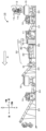
- FIG. 1 is an explanatory diagram showing an example of the configuration of a recycling system 10.
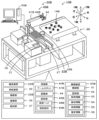
- FIG. 2 is an explanatory diagram showing an example of a schematic configuration of a foreign matter removal device 30.
- FIG. 2 is a perspective view showing an example of a schematic configuration of a removal unit 40.
- 4A and 4B are explanatory diagrams showing examples of captured images 71 and 82 of the detection unit 31.
- FIG. 4 is an explanatory diagram showing an example of information stored in a storage unit 52.
- 10 is a flowchart showing an example of a foreign matter removal processing routine.
- 4 is a flowchart showing an example of a state estimation processing routine.
- FIG. 4 is an explanatory diagram showing an example of a notification screen 80 displayed on the display unit 38.
- FIG. 2 is an explanatory diagram showing an example of the configuration of a collection system 10B.
- FIG. 1 is an explanatory diagram showing an example of the configuration of a recycling system 10 for recycling waste materials, shown as an example of a collection system.
- FIG. 2 is an explanatory diagram showing an example of the schematic configuration of a foreign matter removal device 30.
- FIG. 3 is a perspective view showing an example of the schematic configuration of a removal unit 40.
- FIG. 4 is an explanatory diagram showing an example of captured images 71, 82 captured by the detection unit 31.
- FIG. 5 is an explanatory diagram showing an example of collection information 53, detection information 54, processing information 55, and estimated information 56 stored in the storage unit 52. Note that in this embodiment, the left-right direction, front-rear direction, and up-down direction are as shown in FIGS. 1 to 4. Also, in this embodiment, the direction in which the processing material 12 to be processed is transported is referred to as the transport direction D.
- the material to be treated 12 in the recycling system 10 is a mixture of waste materials 13 to be recycled, such as stones, sand, and concrete, and foreign matter 14, including paper, resin, wood, and metal.
- the recycling system 10 includes a primary crusher 15, a primary magnetic separator 16, a screener 17, a foreign matter removal device 30, a secondary crusher 18, a secondary magnetic separator 19, and conveying devices 20 to 25.
- the primary crusher 15 is a device that performs primary crushing of the raw material 12.
- the primary crusher 15 crushes the treated material 12 to a predetermined primary size or less (e.g., 40 cm or less).
- the primary magnetic separator 16 is a device that removes magnetic foreign matter contained in the treated material 12 by magnetic force.
- the screener 17 is a device that separates the treated material 12 of a primary size or more from the treated material 12 of a smaller size by passing the treated material 12 over a mesh, for example.
- the secondary crusher 18 is a device that performs secondary crushing of the treated material 12 to a size smaller than that of the primary crusher 15.
- the secondary crusher 18 crushes the treated material 12 to a predetermined secondary size or less (e.g., 10 cm or less).
- the secondary magnetic separator 19 is a device that removes magnetic material from the treated material 12 that could not be completely removed by the primary magnetic separator 16 and the foreign matter removal device 30.
- the conveying devices 20 to 25 serving as the conveying line are devices that place the treatment material 12 on a conveying surface and convey it along the conveying direction D, and are configured, for example, as belt conveyors. Note that the conveying devices 20 to 25 may be configured in a manner other than a belt conveyor, so long as they are capable of conveying the treatment material 12.
- the detection unit 31 is a device that detects the waste material 13 and foreign matter 14.
- the detection unit 31 is arranged upstream of the removal unit 40 in the conveying direction D.
- the detection unit 31 includes an imaging unit 32 that images the treatment material 12 including the waste material 13 and foreign matter 14 conveyed by the conveying unit 22, and a measurement unit 33 that measures the height of the treatment material 12.
- the imaging unit 32 is configured, for example, as a camera that captures an image of the treatment material 12 placed on the conveying surface of the conveying device 22 and conveyed.
- the imaging unit 32 captures an image of a predetermined range including the treatment material 12 from above the conveying surface of the conveying device 22, and outputs the image data to the control device 50. As shown in FIG.
- the imaging unit 32 captures captured images 71 and 82 including the waste material 13 and foreign matter 14.
- the captured image 71 is an example of an image in a state in which the treatment material 12 is not being conveyed on the conveying device 22.
- the captured image 72 is an example of an image of the processing material 12 and the foreign matter 14 being transported on the transport device 22.
- the measuring unit 33 detects the height of the processing material 12 and the like on the transport device 22.
- the measuring unit 33 may be provided upstream of the removing unit 40 in the transport direction D and configured as a stereo camera equipped with two cameras.
- the measuring unit 33 may be a sensor that detects a reflected wave obtained by irradiating the transport surface and obtains the height of the reflection position.
- the imaging unit 32 and the measuring unit 33 are held above the transport surface of the transport device 22 by a holding member provided to straddle the transport device 22 in the left-right direction.
- the measuring unit 33 outputs information regarding the detected height of the processing material 12 to the control device 50.
- the foreign matter removal device 30 equipped with the measuring unit 33 can control the transport of the processing material 12 using information on the height direction of the processing material 12.
- the foreign matter removal device 30 may omit either the imaging unit 32 or the measuring unit 33 as long as the height of the processing material 12 can be measured.
- the disposal section 36 is a dust box that serves as a storage section for storing the foreign objects 14.
- the foreign objects 14 collected by the collection section 45 of the removal section 40 are dropped into the disposal section 36.
- the disposal section 36 may have multiple storage containers and separate the foreign objects 14 according to their weight and material.
- a detection section 37 that detects the dropped object is disposed on the edge of the opening of the disposal section 36.
- the detection section 37 is configured as a device that detects the passage of the foreign object 14 when the foreign object 14 is stored in the disposal section 36 in which the foreign object 14 is placed.
- the detection section 37 may be, for example, a sensor that can detect a passing object, such as a non-contact sensor.
- the detection section 37 may be an area sensor whose detection area is the entire opening of the disposal section 36.
- the non-contact sensor may be, for example, one that includes an irradiation section that irradiates infrared rays or laser light and a light receiving section that detects the irradiated direct light or reflected light.
- the detection unit 37 may capture an image of the entire opening of the disposal unit 36 and detect the passage of an object from the captured image.
- the removal unit 40 is a device that uses a collection member 49 to collect and remove objects such as foreign matter 14 contained in the treatment material 12 transported in the transport direction D by the transport device 22.
- the removal unit 40 is configured, for example, as an XY robot.
- the removal unit 40 detects and removes foreign matter 14 present in the treatment material 12 based on the image captured by the imaging unit 32.
- the removal unit 40 is provided downstream of the detection unit 31 in the transport direction D.
- the removal unit 40 includes an X-axis slider 41, a Y-axis slider 43, and a collection unit 45.
- the removal unit 40 discards the collected foreign matter 14 into a disposal unit 36 disposed to the side of the transport device 22.
- the removal unit 40 may be configured in other ways, such as a multi-joint arm robot.
- the X-axis slider 41 is provided with a drive mechanism.
- This drive mechanism 42 includes a guide rail installed along a direction perpendicular to the transport direction D of the transport device 22, a slider that moves along the guide rail, and a drive motor that drives the slider.
- the guide rail is fixed to the slider of the Y-axis slider 43 installed on the transport section 22 along the transport direction D.
- a removal head 48 with a lifting section 46 is fixed to the slider of the X-axis slider 41.
- the drive mechanism may be, for example, a linear motion mechanism using a ball screw equipped with a screw shaft and a nut. Note that the drive mechanism is not particularly limited as long as it is a linear motion mechanism, and may be a linear motor or the like.
- the collection unit 45 is a unit that collects objects such as foreign matter 14 using a collection member 49, and includes, for example, a lifting unit 46, a removal head 48, and a collection member 49.
- the lifting unit 46 is a drive mechanism fixed to the removal head 48 arranged on the X-axis slider 41, and raises and lowers the collection member 49 along the Z-axis direction. This drive mechanism may be the same as the drive mechanism of the X-axis slider 41 or the Y-axis slider 43.
- the collection unit 45 is provided with a camera and/or a sensor, and is configured to be able to acquire information on the foreign matter 14 grasped by the collection member 49.
- the collection member 49 is a member that collects objects, and may be a gripping claw that grasps the object.
- the collection member 49 may be a suction nozzle that adsorbs the object by negative pressure.
- the collection unit 45 grasps and releases the foreign matter 14 by opening and closing the collection member 49, and collects and removes it from the treatment material 12.
- the collection unit 45 opens and closes the collection member 49 using a gripping drive unit (not shown).
- the collection member 49 is moved in the X, Y, and Z directions within a predetermined range of the transport unit 22 by the X-axis slider 41, the Y-axis slider 43, and the lift unit 46.
- the control device 50 is a device that controls the entire foreign body removal device 30, and is equipped with a control unit 51 and a memory unit 52.
- the control unit 51 is configured as a microprocessor centered on a CPU, and controls the entire device.
- the control unit 51 outputs control signals to the detection unit 31 and the removal unit 40, and inputs signals from the detection unit 31 and the removal unit 40.
- the memory unit 52 is a storage medium that stores information, and is configured, for example, with a HDD or flash memory. As shown in FIG. 5, the memory unit 52 stores, for example, collection information 53, detection information 54, processing information 55, and estimation information 56.
- the estimated information 56 includes one or more of the states of the collection member 49, for example, a state requiring inspection that requires inspection, a state requiring maintenance that requires maintenance, and a state requiring repair that requires repair due to a fault diagnosis.
- the collection information 53, the detection information 54, the processing information 55, and the estimated information 56 are associated with each period, for example, every hour, every day, or every week.
- the control unit 51 executes a process to obtain the processing information 55 regarding the success of the collection and movement of the foreign body 14 and/or the failure of the collection and movement of the foreign body 14 based on the collection information 53 and the detection information 54.
- the control unit 51 outputs the estimated information 56 that estimates the state of the collection member 49 based on the collection information 53 and the detection information 54.
- the control device 50 is also connected to a display unit 38 and an input unit 39.
- the display unit 38 is a display that displays images.
- the input unit 39 accepts input from the worker M and includes a keyboard, mouse, etc.
- FIG. 6 is a flowchart showing an example of a foreign matter removal process routine executed by the control unit 51 of the control device 50. This routine is stored in the storage unit 52, and is executed by the control unit 51 after the foreign matter removal device 30 is started.
- the control unit 51 first drives the transport device 22 (S100) and determines whether it is time to detect a foreign matter (S110).
- the foreign matter detection timing may be, for example, the timing when the image capture unit 32 captures all of the processing material 12 transported by the transport device 22 in a continuous still image, and the still image moves to the next image.
- the detection timing can be the passage of a certain period of time when a still image is acquired.
- the detection timing in the measurement unit 33 can be, for example, every time a certain period of time passes, or can be the same as the detection timing of the imaging unit 32.
- the control unit 51 acquires the image captured by the imaging unit 32 and the height value measured by the measurement unit 33, and performs detection processing for the waste material 13 and the foreign object 14 using the captured image and the height value (S120). As part of the detection processing for the waste material 13, the control unit 51 performs processing to detect an area that differs in brightness from the conveying surface of the conveying device 22, for example, and to determine that area as the area of the material 12 to be treated. The control unit 51 may also determine the area of the waste material 13 from the acquired height of the conveying surface. Furthermore, the control unit 51 can determine the presence or absence of a foreign object 14 based on whether or not there is an area of the foreign object 14 in the captured image (see FIG. 4).
- the control unit 51 determines whether or not a foreign object 14 is present in the captured image of the transport device 22 (S130). When a foreign object 14 is present in the transport device 22, the control unit 51 executes a collection process for the foreign object 14 (S140). In the collection process for the foreign object 14, the control unit 51 sets a movement path for collecting the foreign object 14 and releasing it in the disposal unit 36, and moves the collection member 49 to the location of the foreign object 14 in accordance with the movement speed of the foreign object 14 to collect the foreign object 14.
- the control unit 51 increments the number of attempts to collect the foreign object 14 during the corresponding period included in the collection information 53 by 1 (S150), and determines whether the collection of the foreign object 14 was successful using the captured image of the collection member 49, the sensor output value, etc. (S160).
- the control unit 51 increments the actual number of collections in the collection information 53 during the corresponding period by 1 to update it (170).
- control unit 51 moves the collection member 49 to a release position for the foreign object 14 set on the disposal unit 36, releases the foreign object 14, and moves the collection member 49 to the planned initial position (S180).
- the control unit 51 determines whether or not the passage of the foreign object 14 has been detected based on a detection signal from the detection unit 37 disposed in the disposal unit 36 (S190). When the passage of the foreign object 14 is detected, the control unit 51 increments the number of passages included in the detection information 54 during the corresponding period by one and updates it (S200).
- the control unit 51 determines whether the regeneration process of the treatment material 12 is complete (S210). When the regeneration process of the treatment material 12 is not complete, the control unit 51 executes the processes from S110 onwards. That is, the control unit 51 detects the foreign object 14, and repeatedly executes the process of removing the foreign object 14 while updating the number of trials, the number of actual collections, the number of passes, etc. On the other hand, when the regeneration process of the treatment material 12 is complete in S210, the control unit 51 stops the transport device 22 (S220) and ends this routine.
- FIG. 7 is a flowchart showing an example of a state estimation process routine executed by the control unit 51 of the control device 50.
- This routine is stored in the storage unit 52, and is executed in parallel with the execution of the foreign body removal process routine after the foreign body removal device 30 is started.
- the control unit 51 first determines whether it is an estimation timing for estimating the state of the collection member 49 (S300).
- the estimation timing may be any timing that allows the state of the collection member 49 to be appropriately determined, and can be set, for example, when a period of information stored in the storage unit 52 has elapsed.
- the control unit 51 determines the success rate and/or failure rate of collecting the foreign body 14 based on the most recent collection information 53 and detection information 54, and updates the processing information (S310). For example, the control unit 51 can determine the success rate from the following formula 1 or formula 2. Alternatively, the control unit 51 can determine the failure rate from the following formula 3 or 4. Regarding the success rate and failure rate, when the actual number of collections is used, the falling of the foreign matter 14 from collection to release can be grasped, and when the number of attempts is used, the failure to collect the foreign matter 14 and the falling of the foreign matter 14 from collection to release can be grasped.
- the configuration for detecting the success of collection of the foreign matter 14 can be omitted in the foreign matter removal device 30.
- the processing information 55 may include the number of successes in addition to or instead of the success rate.
- the processing information 55 may include the number of failures in addition to or instead of the failure rate.
- the number of successes is represented by the number of passes, and the number of failures is the value obtained by subtracting the number of passes from the number of attempts or the actual number of collections.
- Success rate (%) 100 - (number of trials - number of passes) / (number of trials) x 100...
- the control unit 51 determines whether the obtained success rate is below a predetermined allowable value (S320).
- the allowable value may be empirically set to a value that can predict that the collection member 49 has a defect.
- the range of the allowable value is determined as a first range value that requires inspection (e.g., a success rate of less than 95%), a second range that requires maintenance (e.g., a success rate of less than 90%), and a third range that requires repair (e.g., a success rate of less than 85%).
- the control unit 51 checks which allowable value range the success rate is in (S330), and when the success rate is within the first range, the control unit 51 displays and outputs the inspection information to the display unit 38 as estimated information of the collection member 49 (S340).
- the inspection information includes information that prompts the execution of an inspection of the collection member 49.
- the control unit 51 displays and outputs the maintenance information to the display unit 38 as estimated information of the collection member 49 (S350).
- the maintenance information includes information that prompts the execution of maintenance of the collection member 49.
- malfunction information is displayed on the display unit 38 as estimated information of the collection member 49 (S360).
- the malfunction information includes information that prompts the user to repair the collection member 49.
- the control unit 51 determines whether the obtained success rate is below a predetermined allowable value, but is not limited to this, and may determine whether the obtained failure rate exceeds a predetermined limit value.
- the limit value may be empirically set to a value that can predict that there is a defect in the collection member 49.
- the limit value is set to a first limit value that requires inspection (for example, a failure rate exceeding 5%), a second allowable value that requires maintenance (for example, a failure rate exceeding 10%), a third allowable value that requires repair (for example, a failure rate exceeding 15%), etc.
- control unit 51 may determine whether the failure rate is in the first range, the second range, or the third range, and display and output inspection information in the first range, maintenance information in the second range, and failure information in the third range.
- the notification screen 80 includes a cursor 81, an estimated information display field 82, a processing information display field 83, and a confirmation key 84.
- the cursor 81 is operated by the worker M when selecting information.
- the estimated information display field 82 includes information on the estimated state of the collection member 49 and the work to be performed.
- the processing information display field 83 includes information such as the current collection information 53, the detection information 54, the processing information 55, and the estimated information 56.
- the confirmation key 84 is a key that is pressed by the worker M after checking the displayed information. Note that the notification screen 80 in FIG. 8 displays inspection information, but the notification screen 80 may also display maintenance information, failure information, and the like. The worker M can check the contents of the notification screen 80, recognize the state of the collection member 49, and check the state of the collection member 49.
- the collection member 49 that grasps the waste material 13 such as rubble and the foreign object 14 is at high risk of damage.
- damage to the collection member 49 include wear and cracks on the contact surface caused by contact with the waste material 13.
- damage to the collection member 49 can be detected by taking an image of the collection member 49 with a camera or by contacting it with a contact sensor.
- both of the above methods require additional equipment such as a camera or sensor, and a confirmation operation must be performed during operation, which may reduce the efficiency of the removal process of the foreign object 14.
- the condition of the collection member 49 can be estimated by detecting the number of removal attempts and actual collections of the collection member 49, and the number of passes through the disposal section 36, which are usually configured to be countable. For example, if the success rate of removing the foreign object 14 is gradually decreasing, the control unit 51 can estimate the condition of the collection member 49, such as wear, and can urge the operator M to inspect or maintain it. Alternatively, if the success rate of removing the foreign body 14 suddenly drops, the control unit 51 can estimate a faulty state, such as damage to the collection member 49, and can urge the worker M to repair the damage. Note that even when the failure rate is used, the control unit 51 can estimate the state of the collection member 49 in the same way as the success rate.
- the control unit 51 determines whether the recycling process of the processing material 12 has been completed (S370). When the recycling process of the processing material 12 has not been completed, the control unit 51 executes the processes from S300 onwards. That is, when it is the estimation timing, the control unit 51 updates the processing information 55 and the like, and reports information regarding the state of the collection member 49 estimated from the processing information 55 to the operator M. On the other hand, when the recycling process of the processing material 12 has been completed in S370, the control unit 51 ends this routine.
- the control device 50 of this embodiment corresponds to an example of a control device of this disclosure
- the foreign matter removal device 30 corresponds to an example of a collection device and foreign matter removal device
- the collection section 45 corresponds to an example of a collection section
- the disposal section 36 corresponds to an example of a storage section
- the detection section 37 corresponds to an example of a detection section
- the control section 51 corresponds to an example of a control section
- the transport device 22 corresponds to an example of a transport device
- the processing material 12 corresponds to an example of a target object. Note that in this embodiment, by explaining the operation of the foreign matter removal device 30, an example of an information processing method of this disclosure is also clarified.
- the foreign matter removal device 30 described above is configured as a collection device of the present disclosure, and includes a collection section 49 that collects foreign matter 14 as a target contained in the treatment material 12 transported in the transport direction D by the transport device 22 using a collection member 49, a detection section 37 that detects the passage of the foreign matter 14 when the foreign matter 14 collected by the collection section 45 is stored in the disposal section 36 as a storage section in which the foreign matter 14 is placed, a detection section 31 that is located upstream of the collection section 45 in the transport direction D and detects the foreign matter 14, and a control device 50 that includes a control unit 51, and the control unit 51 controls the collection section 45 to collect the foreign matter 14 based on the detection result of the detection section 31 and discard it in the disposal section 36.
- the control unit 51 also obtains processing information 55 regarding the success of the collection and movement of the foreign matter 14 and/or the failure of the collection and movement of the target based on collection information 53 regarding the collection of the foreign matter 14 and detection information 54 of the foreign matter 14 detected by the detection section 37.
- This control device 50 can detect the passage of the foreign object 14 and detect that the foreign object 14 has been moved to the disposal section 36. Furthermore, by using the collection information 53 and the detection information 54, the control device 50 can digitize information regarding the success or failure of collection of the foreign object 14 without inspecting the collection member 49 itself. Therefore, by using this digitized content, this control device 50 can estimate the state of the collection member 49, and the efficiency of the work of collecting the target object and moving it to the storage section can be further improved.
- the control unit 51 also outputs estimated information 56 that estimates the state of the collection member based on the collection information 53 and the detection information 54.
- the control device 50 can detect the passage of the foreign object 14 and detect that the foreign object 14 has been moved to the disposal section 36.
- the control device 50 can also obtain information on the success or failure of collection of the foreign object 14 by the collection member 49 without inspecting the collection member 49 itself by using the collection information 53 of the foreign object 14, and can estimate the state of the collection member 49. Therefore, the control device 50 can further improve the work efficiency of collecting the foreign object 14 and moving it to the disposal section 36 by using the estimated state of the collection member 49.
- the control device 50 also outputs estimated information 56 that estimates the state of the collection member 49 based on the obtained processing information 55.
- the control device 50 can estimate the state of the collection member 49 by using information on the success or failure of collection of the foreign object 14 without inspecting the collection member 49 itself.
- the control device 50 can improve the efficiency of the work of collecting foreign matter 14 and moving it to the disposal section 36 by taking action according to the state of the collection member 49.
- the control section 51 uses collection information 53 including the number of attempts to collect foreign matter 14 and/or the number of actual collections in which a state in which foreign matter 14 has been collected is detected.
- the control device 50 can improve the efficiency of the work of collecting foreign matter 14 and moving it to the disposal section 36 by using the number of attempts and the number of actual collections.
- the control unit 51 also obtains processing information 55 including a success rate and/or number of successes from the collection information 53 and the detection information 54.
- the success rate and number of successes of the collection process can be used to further improve the efficiency of the work of collecting foreign bodies 14 and moving them to the disposal section 36.
- the control unit 51 outputs estimated information 56 that estimates the state of the collection member 49 when the obtained success rate and/or number of successes falls below a predetermined allowable value.
- the control unit 51 obtains processing information 55 including a failure rate and/or number of failures from the collection information 53 and the detection information 54.
- the failure rate and number of failures of the collection process can be used to further improve the efficiency of the work of collecting foreign bodies 14 and moving them to the disposal section 36.
- the control unit 51 outputs estimated information 56 that estimates the state of the collection member 49 when the obtained failure rate and/or number of failures exceed a predetermined limit value.
- the control unit 51 outputs inferred information 56 including one or more of failure information including a failure diagnosis of the collection member 49, maintenance information for performing maintenance on the collection member 49, and inspection information for performing an inspection of the collection member 49.
- This control device uses the failure information, maintenance information, and inspection information to further improve the condition of the collection member, thereby further improving the efficiency of the work of collecting the target object and moving it to the storage unit.
- the control unit 51 obtains processing information 55 regarding successful collection and movement of the foreign body 14 and failure to collect and move the foreign body 14 based on the collection information 53 and the detection information 54, and notifies the estimated information 56 based on the processing information 55, but this is not particularly limited, and either obtaining the processing information 55 or notifying the estimated information 56 may be omitted. Also, the control unit 51 obtains processing information 55 regarding successful collection and movement of the foreign body 14 and failure to collect and move the foreign body 14, but this is not particularly limited, and either successful collection and movement or failure to collect and move the foreign body 14 may be omitted. Even in such a control device 50, the efficiency of the work of collecting the foreign body 14 and moving it to the disposal unit 36 can be further improved by any of the processes.
- the collection information 53 includes the number of trials and the number actually collected, but this is not limited to this and any of these may be omitted.
- the estimated information 56 includes failure information, maintenance information, and inspection information, but this is not limited to this and any one or more of these may be omitted. Even in this control device 50, the work efficiency of collecting foreign matter 14 and moving it to the disposal section 36 can be further improved by any of the processes.
- FIG. 9 is an explanatory diagram showing an example of the configuration of another collection system 10B.
- This collection system 10B has a conveying device 22B, a supplying device 26, a collection device 30B, a disposal unit 36, and a detection unit 37.
- the collection device 30B is composed of the detection unit 37 arranged in the disposal unit 36, a processing unit 40B having a collection unit 45B, and a control device 50B having a control unit 51.
- This collection device 30B is a device that processes and places parts as the target object 14B placed in the supplying device 26 on the placement member 27 transported by the conveying device 22B.
- the collection device 30B determines whether or not there is a defect in the target object 14B based on an image captured by the imaging unit 32B, and discards the target object 14B with a defect to the disposal unit 36.
- the disposal unit 36 is a storage unit in which the object 14B collected by the collection unit 45B is placed.
- the detection unit 37 is a sensor that detects the passage of the object 14B when the object 14B is stored in the disposal unit 36.
- the collection unit 45B collects the object 14 with a collection member 49B.
- the collection unit 45B includes an arm robot 41B, a recognition unit 44, and the collection unit 45B.
- the arm robot 41B has a plurality of arms, and moves the collection unit 45B between the supply device 26, the transport device 22B, and the disposal unit 36.
- the recognition unit 44 is disposed in the collection unit 45B, and captures an image of the object 14B on the supply device 26, etc.
- the collection unit 45B includes a collection head 48B disposed at the tip of the arm robot 41B, and a collection member 49B attached to the collection head 48B and having a gripping claw. Like the control device 50 described above, this control device 50B obtains processing information 55 from collection information 53 and detection information 54, or reports estimated information 56. Since this collection device 30B is equipped with the above-mentioned control device 50B, it is possible to further improve the work efficiency of collecting the object 14B and moving it to the disposal section 36 as a storage section. With this collection device 30B, it is possible to further improve the work efficiency of collecting the object 14B and moving it to the disposal section 36.
- the objects are disposed of in the disposal section 36, but this is not limited to disposal, and the number of objects passing through the storage section may be counted when the objects are stored in the storage section.
- this collection device as well, the work efficiency of collecting objects and moving them to the storage section can be further improved.
- the present disclosure has been described as a foreign matter removal device 30 equipped with a control device 50, but is not particularly limited to this, and the present disclosure may be the control device 50 itself, a control method for the foreign matter removal device 30 executed by a computer, a program for this control method, or an information processing method executed by the control device 50, or a program for this method.
- control device method of the present disclosure may be configured as follows:
- the control device of the present disclosure is a control device used in a collection device including a collection unit that collects an object with a collection member, and a detection unit that detects the passage of an object when the object collected by the collection unit is stored in a storage unit in which the object is placed, a control unit that outputs inferred information that estimates a state of the collection member based on collection information regarding the collection of the object and detection information of the object detected by the detection unit; It is equipped with the following:
- This control device can detect the passage of an object and detect that the object has been moved to the storage section. Furthermore, by using information regarding the collection of the object, the control device can obtain information regarding the success or failure of the collection of the object by the collection member without inspecting the collection member itself, and can estimate the state of the collection member. Therefore, by using this estimated state of the collection member, this control device can further improve the efficiency of the work of collecting the object and moving it to the storage section.
- the information processing method of the present disclosure includes: An information processing method executed by a computer and used in a collection device including a collection unit that collects an object with a collection member and a detection unit that detects the passage of an object when the object collected by the collection unit is stored in a storage unit in which the object is stored, comprising: A step of obtaining processing information regarding success in collecting and moving the object and/or failure in collecting and moving the object based on collection information regarding the collection of the object and detection information of the object detected by the detection unit; It includes.
- the information processing method of the present disclosure includes: An information processing method executed by a computer and used in a collection device including a collection unit that collects an object with a collection member and a detection unit that detects the passage of an object when the object collected by the collection unit is stored in a storage unit in which the object is stored, comprising: A step of outputting estimated information that estimates a state of the collection member based on collection information regarding the collection of the object and detection information of the object detected by the detection unit; It includes.
- this information processing method similar to the control device described above, it is possible to obtain information regarding the success or failure of collection of the object by the collection member, and by estimating the state of the collection member, it is possible to further improve the efficiency of the work of collecting the object and moving it to the storage section. Note that in this information processing method, various aspects of the control device described above may be adopted, and steps may be added that realize each function of the control device described above.
- This disclosure can be used in technical fields such as industrial waste recycling.
- 10 Recycling system 10B Collection system, 12 Processing material, 13 Waste material, 14 Foreign matter, 14B Target object, 15 Primary crusher, 16 Primary magnetic separator, 17 Screening machine, 18 Secondary crusher, 19 Secondary magnetic separator, 20-25, 22B Conveyor, 26 Supply device, 30 Foreign matter removal device, 30B Collection device, 31 Detection unit, 32, 32B Imaging unit, 33 Measurement unit, 35 Support unit, 36, 36B Disposal unit, 37, 37B Detection unit, 40 Removal unit, 40B Processing unit, 41 X-axis scan Rider, 41B arm robot, 43 Y-axis slider, 44 recognition unit, 45, 45B collection unit, 46 lifting unit, 48 removal head, 48B collection head, 49, 49B collection member, 50, 50B control device, 51 control unit, 52 memory unit, 53 collection information, 54 detection information, 55 processing information, 56 estimated information, 71 captured image, 72 captured image, 80 notification screen, 81 cursor, 82 estimated information display field, 83 processing information display field, 84 confirmation key, D transport direction, M operator.
Landscapes
- Manipulator (AREA)
- Processing Of Solid Wastes (AREA)
- Sorting Of Articles (AREA)
Priority Applications (4)
| Application Number | Priority Date | Filing Date | Title |
|---|---|---|---|
| CN202280101534.6A CN120076872A (zh) | 2022-12-20 | 2022-12-20 | 控制装置、异物去除装置、拾取装置及信息处理方法 |
| JP2024565458A JPWO2024134783A1 (https=) | 2022-12-20 | 2022-12-20 | |
| PCT/JP2022/046935 WO2024134783A1 (ja) | 2022-12-20 | 2022-12-20 | 制御装置、異物除去装置、採取装置及び情報処理方法 |
| EP22969172.0A EP4640323A4 (en) | 2022-12-20 | 2022-12-20 | CONTROL DEVICE, FOREIGN BODY REMOVAL DEVICE, INFORMATION COLLECTION DEVICE AND PROCESSING METHOD |
Applications Claiming Priority (1)
| Application Number | Priority Date | Filing Date | Title |
|---|---|---|---|
| PCT/JP2022/046935 WO2024134783A1 (ja) | 2022-12-20 | 2022-12-20 | 制御装置、異物除去装置、採取装置及び情報処理方法 |
Publications (1)
| Publication Number | Publication Date |
|---|---|
| WO2024134783A1 true WO2024134783A1 (ja) | 2024-06-27 |
Family
ID=91588132
Family Applications (1)
| Application Number | Title | Priority Date | Filing Date |
|---|---|---|---|
| PCT/JP2022/046935 Ceased WO2024134783A1 (ja) | 2022-12-20 | 2022-12-20 | 制御装置、異物除去装置、採取装置及び情報処理方法 |
Country Status (4)
| Country | Link |
|---|---|
| EP (1) | EP4640323A4 (https=) |
| JP (1) | JPWO2024134783A1 (https=) |
| CN (1) | CN120076872A (https=) |
| WO (1) | WO2024134783A1 (https=) |
Citations (4)
| Publication number | Priority date | Publication date | Assignee | Title |
|---|---|---|---|---|
| JP2014039978A (ja) * | 2012-08-22 | 2014-03-06 | Toyota Industries Corp | 把持装置 |
| JP2020040159A (ja) * | 2018-09-10 | 2020-03-19 | 株式会社東芝 | 情報処理装置、ピッキングロボットシステム、情報処理方法及び情報処理プログラム |
| JP2021164903A (ja) | 2020-04-06 | 2021-10-14 | 株式会社物井工機 | 回収物分別システム |
| JP7154072B2 (ja) * | 2018-09-11 | 2022-10-17 | 三菱電機株式会社 | 搬送装置及び搬送ロボット |
Family Cites Families (2)
| Publication number | Priority date | Publication date | Assignee | Title |
|---|---|---|---|---|
| EP1518611A3 (de) * | 2003-09-29 | 2005-05-18 | visicontrol Gesellschaft für elektronische Bildverarbeitung mbH | Verfahren und Vorrichtung zum Sortieren von vereinzelten Prüflingen mittels Bildverarbeitung |
| EP3323517B1 (de) * | 2016-11-18 | 2019-03-27 | Siemens Aktiengesellschaft | Sortiersystem und verfahren zur verfolgung eines einsortierens eines sortierguts in ein sortierregister |
-
2022
- 2022-12-20 EP EP22969172.0A patent/EP4640323A4/en active Pending
- 2022-12-20 WO PCT/JP2022/046935 patent/WO2024134783A1/ja not_active Ceased
- 2022-12-20 JP JP2024565458A patent/JPWO2024134783A1/ja active Pending
- 2022-12-20 CN CN202280101534.6A patent/CN120076872A/zh active Pending
Patent Citations (4)
| Publication number | Priority date | Publication date | Assignee | Title |
|---|---|---|---|---|
| JP2014039978A (ja) * | 2012-08-22 | 2014-03-06 | Toyota Industries Corp | 把持装置 |
| JP2020040159A (ja) * | 2018-09-10 | 2020-03-19 | 株式会社東芝 | 情報処理装置、ピッキングロボットシステム、情報処理方法及び情報処理プログラム |
| JP7154072B2 (ja) * | 2018-09-11 | 2022-10-17 | 三菱電機株式会社 | 搬送装置及び搬送ロボット |
| JP2021164903A (ja) | 2020-04-06 | 2021-10-14 | 株式会社物井工機 | 回収物分別システム |
Non-Patent Citations (1)
| Title |
|---|
| See also references of EP4640323A1 |
Also Published As
| Publication number | Publication date |
|---|---|
| EP4640323A1 (en) | 2025-10-29 |
| JPWO2024134783A1 (https=) | 2024-06-27 |
| EP4640323A4 (en) | 2026-01-21 |
| CN120076872A (zh) | 2025-05-30 |
Similar Documents
| Publication | Publication Date | Title |
|---|---|---|
| CN104441526B (zh) | 基于外形轮廓匹配的模具在线监视保护系统及方法 | |
| JP2007517641A (ja) | 留め具(ファスナー)の点検装置 | |
| US20170036245A1 (en) | Inspection and sorting machine | |
| CN113758926A (zh) | 具有视觉检查站的产品组装机 | |
| KR101772849B1 (ko) | 트레이 불량검사 장치 및 불량검사 방법 | |
| CN115485095A (zh) | 滑移件状态判定装置、滑移件状态判定方法及激光加工系统 | |
| JP2025060801A (ja) | 廃材処理システム | |
| JP2025129287A (ja) | 異物除去方法 | |
| JP7787755B2 (ja) | 制御装置、異物除去装置及び制御方法 | |
| WO2024134783A1 (ja) | 制御装置、異物除去装置、採取装置及び情報処理方法 | |
| JP5440015B2 (ja) | 不良蓋排除装置及び不良蓋排除方法 | |
| CN116448780A (zh) | 芯片缺陷检测装置、方法及设备 | |
| CN111790629A (zh) | 一种智能自动化刀具检测方法及装置 | |
| JP7663588B2 (ja) | 異物除去装置 | |
| JP3795463B2 (ja) | バルク包装に用いるセパレートシート清掃装置 | |
| EP4685087A1 (en) | Foreign matter removal device and control method for foreign matter removal device | |
| CN115889247B (zh) | 一种散料异物检测方法及装置、x光机异物检测设备 | |
| CN118720432A (zh) | 激光打标方法、装置、电子设备和存储介质 | |
| JP2026005277A (ja) | 異物除去装置及び異物除去方法 | |
| WO2026004713A1 (ja) | 異物除去装置、選別装置、異物除去方法及び選別方法 | |
| EP4691705A1 (en) | Foreign matter removal device and foreign matter removal method | |
| WO2024041263A1 (zh) | 一种散料异物检测方法及装置、x光机异物检测设备 | |
| WO2024257234A1 (ja) | 採取装置、異物除去装置及び採取方法 | |
| WO2024100751A1 (ja) | 異物除去装置、ピッキングチャック及び制御方法 | |
| WO2025027820A1 (ja) | 異物除去装置及び異物除去方法 |
Legal Events
| Date | Code | Title | Description |
|---|---|---|---|
| 121 | Ep: the epo has been informed by wipo that ep was designated in this application |
Ref document number: 22969172 Country of ref document: EP Kind code of ref document: A1 |
|
| WWE | Wipo information: entry into national phase |
Ref document number: 202280101534.6 Country of ref document: CN |
|
| WWP | Wipo information: published in national office |
Ref document number: 202280101534.6 Country of ref document: CN |
|
| WWE | Wipo information: entry into national phase |
Ref document number: 2024565458 Country of ref document: JP |
|
| WWE | Wipo information: entry into national phase |
Ref document number: 2022969172 Country of ref document: EP |
|
| NENP | Non-entry into the national phase |
Ref country code: DE |
|
| ENP | Entry into the national phase |
Ref document number: 2022969172 Country of ref document: EP Effective date: 20250721 |
|
| ENP | Entry into the national phase |
Ref document number: 2022969172 Country of ref document: EP Effective date: 20250721 |
|
| ENP | Entry into the national phase |
Ref document number: 2022969172 Country of ref document: EP Effective date: 20250721 |
|
| WWP | Wipo information: published in national office |
Ref document number: 2022969172 Country of ref document: EP |