WO2024134744A1 - ビーム装置、ラメラ抽出装置、ラメラ観察システムおよびラメラ作製方法 - Google Patents
ビーム装置、ラメラ抽出装置、ラメラ観察システムおよびラメラ作製方法 Download PDFInfo
- Publication number
- WO2024134744A1 WO2024134744A1 PCT/JP2022/046768 JP2022046768W WO2024134744A1 WO 2024134744 A1 WO2024134744 A1 WO 2024134744A1 JP 2022046768 W JP2022046768 W JP 2022046768W WO 2024134744 A1 WO2024134744 A1 WO 2024134744A1
- Authority
- WO
- WIPO (PCT)
- Prior art keywords
- lamella
- mark
- sample
- transfer means
- processing
- Prior art date
- Legal status (The legal status is an assumption and is not a legal conclusion. Google has not performed a legal analysis and makes no representation as to the accuracy of the status listed.)
- Ceased
Links
Images






Classifications
-
- H—ELECTRICITY
- H01—ELECTRIC ELEMENTS
- H01J—ELECTRIC DISCHARGE TUBES OR DISCHARGE LAMPS
- H01J37/00—Discharge tubes with provision for introducing objects or material to be exposed to the discharge, e.g. for the purpose of examination or processing thereof
- H01J37/02—Details
- H01J37/20—Means for supporting or positioning the object or the material; Means for adjusting diaphragms or lenses associated with the support
-
- G—PHYSICS
- G01—MEASURING; TESTING
- G01N—INVESTIGATING OR ANALYSING MATERIALS BY DETERMINING THEIR CHEMICAL OR PHYSICAL PROPERTIES
- G01N1/00—Sampling; Preparing specimens for investigation
- G01N1/28—Preparing specimens for investigation including physical details of (bio-)chemical methods covered elsewhere, e.g. G01N33/50, C12Q
-
- G—PHYSICS
- G01—MEASURING; TESTING
- G01N—INVESTIGATING OR ANALYSING MATERIALS BY DETERMINING THEIR CHEMICAL OR PHYSICAL PROPERTIES
- G01N1/00—Sampling; Preparing specimens for investigation
- G01N1/28—Preparing specimens for investigation including physical details of (bio-)chemical methods covered elsewhere, e.g. G01N33/50, C12Q
- G01N1/32—Polishing; Etching
-
- H—ELECTRICITY
- H01—ELECTRIC ELEMENTS
- H01J—ELECTRIC DISCHARGE TUBES OR DISCHARGE LAMPS
- H01J37/00—Discharge tubes with provision for introducing objects or material to be exposed to the discharge, e.g. for the purpose of examination or processing thereof
- H01J37/26—Electron or ion microscopes; Electron or ion diffraction tubes
-
- H—ELECTRICITY
- H01—ELECTRIC ELEMENTS
- H01J—ELECTRIC DISCHARGE TUBES OR DISCHARGE LAMPS
- H01J37/00—Discharge tubes with provision for introducing objects or material to be exposed to the discharge, e.g. for the purpose of examination or processing thereof
- H01J37/26—Electron or ion microscopes; Electron or ion diffraction tubes
- H01J37/28—Electron or ion microscopes; Electron or ion diffraction tubes with scanning beams
-
- H—ELECTRICITY
- H01—ELECTRIC ELEMENTS
- H01J—ELECTRIC DISCHARGE TUBES OR DISCHARGE LAMPS
- H01J37/00—Discharge tubes with provision for introducing objects or material to be exposed to the discharge, e.g. for the purpose of examination or processing thereof
- H01J37/30—Electron-beam or ion-beam tubes for localised treatment of objects
- H01J37/317—Electron-beam or ion-beam tubes for localised treatment of objects for changing properties of the objects or for applying thin layers thereon, e.g. for ion implantation
-
- H—ELECTRICITY
- H01—ELECTRIC ELEMENTS
- H01J—ELECTRIC DISCHARGE TUBES OR DISCHARGE LAMPS
- H01J2237/00—Discharge tubes exposing object to beam, e.g. for analysis treatment, etching, imaging
- H01J2237/20—Positioning, supporting, modifying or maintaining the physical state of objects being observed or treated
- H01J2237/208—Elements or methods for movement independent of sample stage for influencing or moving or contacting or transferring the sample or parts thereof, e.g. prober needles or transfer needles in FIB/SEM systems
Definitions
- This disclosure relates to a lamella production method and a lamella observation system, and in particular to a technique for producing samples (lamellae) for TEM observation.
- TEMs transmission electron microscopes
- the preparation of TEM samples for observation with a TEM involves a process of producing a lamella (sample piece) by thinning the area including the observation target using a focused ion beam (FIB) or the like, and a process of mounting this on a lamella holder (sample piece holder) for TEM observation.
- FIB focused ion beam
- Methods for mounting the lamella on the lamella holder include a microsampling method using an FIB-SEM composite device, which is a composite device of a focused ion beam device and a scanning electron microscope (SEM), and a method using a glass probe and an optical microscope (see Patent Document 1).
- FIB-SEM composite device which is a composite device of a focused ion beam device and a scanning electron microscope (SEM)
- SEM scanning electron microscope
- a white light interference microscope can obtain a three-dimensional (3D) image by driving an optical system including an interferometer in the focus direction and detecting the position where an interference pattern occurs, so it can be used as a position grasping method.
- 3D three-dimensional
- the position of an inclined surface that is inclined more than the opening angle of the optical system cannot be grasped because the interfering light does not reach the optical system.
- lamella fabrication there is a problem in that the processing time is long in order to fabricate an inclined surface that is smaller than the opening angle of the optical system of the white light interference microscope, which reduces the throughput of the lamella fabrication process.
- a lamella production method in which a lamella is extracted from a sample using a lamella transfer means, the lamella production method comprising the steps of: producing a mark on an inclined surface produced by lamella processing (an inclined surface carved into the portion of the sample where the lamella is to be produced); obtaining surface information by measuring the mark microscopically; and controlling the sample stage or the lamella transfer means so that the distance between the position of the mark and the position of the lamella transfer means is small.
- the shape information of the processed area can be accurately grasped when picking up the lamella, and the tweezers can be prevented from coming into contact with the sample or the processed area when picking up.
- a white light interference microscope is used as an observation tool, and even if the inclined surface produced by lamellar processing is inclined more than the opening angle of the optical system, the lamella can be lifted out safely.
- FIG. 1 is a configuration diagram of a lamella observation system according to an embodiment.
- 1 is a configuration diagram of an FIB-SEM composite apparatus according to an embodiment.
- 1 is a flow chart of a lamella fabrication method showing steps of lamella fabrication and lift-out operations according to an embodiment.
- FIG. 13 shows a lamellar processing region for lift-out according to an embodiment.
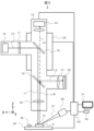
- FIG. 2 is a configuration diagram of a lamella lift-out device according to the embodiment.
- FIG. 2 is a configuration diagram of a lamella holder for TEM observation according to an embodiment.
- 1 is a micrograph of the tweezers and lamella lift-out device in the lamella processing area according to an embodiment.
- the lamella observation system 100 includes a FIB-SEM composite apparatus (a composite apparatus of a focused ion beam apparatus (FIB) and a scanning electron microscope (SEM)) 1, a lamella lift-out apparatus (LLA) 2, and a TEM apparatus (transmission electron microscope: TEM) 3.
- the scanning electron microscope includes a scanning electron microscope barrel.
- the lamella creation process and the mark creation process are carried out by the FIB-SEM composite device 1.
- the mark observation process and the lamella extraction process are carried out by the lamella lift-out device 2.
- the lamella observation process is carried out by the TEM device 3.
- the lamella observation system 100 is An FIB-SEM composite device 1 as a beam device for creating a mark on an inclined surface (object) carved toward a lamella created in a sample by lamella creation processing;
- a lamella lift-out device 2 as a lamella extraction device including a microscope for observing the mark and extracting a lamella from the sample based on the mark;
- a TEM device 3 which is a transmission electron microscope, for observing the extracted lamella; including.
- the lamella lift-out device 2 also includes a second control device 29 as a control unit that comprehensively controls the operation of the lamella lift-out device 2, a second input device 30 connected to the second control device 29, a second display device 31, and a lamella holder 32 for TEM observation.
- a second control device 29 as a control unit that comprehensively controls the operation of the lamella lift-out device 2
- a second input device 30 connected to the second control device 29, a second display device 31, and a lamella holder 32 for TEM observation.
- the white light interference microscope 15 emits light L0 from the light source 16. After passing through the filter 17, the light L0 is reflected by the first beam splitter 18 and is split by the second beam splitter 19 into light L1 that travels toward the sample S, which is the object to be measured, and reference light L2 that travels toward the fixed mirror 22.
- the light L1 passes through the first objective lens 20, where it hits the sample S and is reflected back.
- the reflected light L1R of the light L1 that is reflected back from the sample S is combined by the second beam splitter 19 with the reference light L2 reflected from the fixed mirror 22, and is detected by the photodetector 24 as interference light L3.
- the lamella 12 is formed in the sample S, as explained in FIG. 4.
- the tweezers 27 can be called a sample transfer means or a lamella relocation means.
- the sample transfer means is not limited to the tweezers 27, and for example, a glass probe or a suction probe may also be used.
- the tweezers drive mechanism 28 translates the tweezers 27 tilted at an arbitrary angle in the X-axis, Y-axis, and Z-axis directions while keeping it in that state, or rotates the arms of the tweezers 27 around an axis.
- the mark 14 used in this embodiment makes it possible to detect the slope 13 at an angle that is not possible to measure with the photodetector 24 of a normal white light interference microscope 15.
- the angle of the surface is set to be larger than the measurement limit of the white light interference microscope 15 that performs the microscopic measurement.
- the inclined surface of the slope 13 is inclined with respect to the optical axis of the incident light L1 irradiated by the white light interference microscope 15. In other words, it has a surface that is inclined relative to the surface.
- the mark 14 forms a surface that is different from the surface of the slope 13 (also called the inclined surface or slope surface). Therefore, even if the reflected light L1R from the surface of the slope 13 does not fall within the range of the maximum angle ⁇ , the surface 14S formed by the mark 14 is configured so that the reflected light L1R falls within the range of the maximum angle ⁇ .
- the second control device 29 is configured to be able to grasp information on the position of the lamella 12 and information on the position of the slope 13 from the photodetector 24 of the white light interference microscope 15.
- the mark 14 is processed by performing fine processing on the inclined surface (surface of the slope 13) 119 in the measurement object 118 as the sample S, and by changing the surface shape of the inclined surface 119, a concave processed area 120 or a convex processed area 121 having an angle different from that of the inclined surface 119 is generated.
- the surface of the concave processed area 120 or the convex processed area 121 has a portion (reflective surface) with an inclination at an angle where the reflected light L1R falls within the range of the maximum angle ⁇ of equation (1), so the incident light L1 irradiated to that portion can finally reach the photodetector 24 and become detectable.
- the concave micromachined surface (14S1) and the convex micromachined surface (14S2) are configured so that even if the reflected light L1R from the surface of the slope 13 (inclined surface 119) does not fall within the range of the maximum angle ⁇ , the concave micromachined surface (14S1) and the convex micromachined surface (14S2) as the surface 14S formed by the mark 14 will cause the reflected light L1R to fall within the range of the maximum angle ⁇ .
- Step S1 Slope processing condition determination process
- the first control device 201 controls the position of the sample holder 8, controls the irradiation optical system 4 of the focused ion beam 9 to irradiate the focused ion beam 9, and determines the processing conditions (processing position and processing shape) while checking the sample S by detecting secondary electrons with the electron detector 6.
- the processing conditions are configured to be input and determined using the first input device 202 while checking with the first display device 203.
- the processing conditions include the surface shape of the slope 13 in FIG. 4, the final thickness of the lamella 12, the pattern shape of the mark 14, the position of the mark on the surface of the slope 13, the number of marks 14 processed, the type of concave processing and convex processing, etc.
- the pattern shape of the mark 14 is configured to be selectable from a circular (spot shape) mark SPT, a linear (line shape) mark LIN, a rectangular mark REC, etc., as exemplified in FIG. 10.
- the pattern shape of the mark 14 is not limited to the shape shown in FIG. 10.
- the pattern shape of the mark 14 needs only to have a processed surface or a reflective surface configured so that the reflected light L1R falls within the range of the maximum angle ⁇ .
- the slope machining conditions set in step S1 are referenced, for example, by an operation control program for automatic operation control processing executed by the control circuit (CNT) in the first control device 201. This allows steps S2 and S3 to be performed automatically.
- Step S2 Slope processing step
- a deposition process for protecting the lamella 12 and a process for creating a reference mark REF for improving processing accuracy are performed according to the required specifications for TEM observation (step S21).
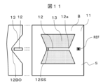
- the first control device 201 irradiates the focused ion beam 9 from the irradiation optical system 4 of the focused ion beam 9 under the processing conditions determined in step S1, and performs a processing process of the slope 13 by sputtering as shown in FIG. 11 (step S22).
- the processing of the slope 13 is a process of forming an inclined surface that is carved toward the portion of the sample S where the lamella 12 is to be produced.
- the processing process of the slope 13 (step S22) can be rephrased as a process of producing an inclined surface.
- the processing of the slope 13 can also be rephrased as a rough processing process of producing the lamella 12 from the sample S.
- the angle of the inclined surface of the slope 13 is set to an angle larger than the measurement limit of the white light interference microscope 15 that performs the microscopic measurement.
- the side 12SS and bottom 12BO of the lamella 12 are etched away while leaving the support portion 12a.
- Step S3 Marking process
- the first control device 201 irradiates the focused ion beam 9, and performs a processing step of the mark 14 by etching processing by sputtering as shown in FIG. 12 (step S31).
- the mark 14 is formed as four circular marks SPT on one surface of the slope 13.
- spot processing is performed.
- line processing is performed.
- the mark 14 is a rectangular mark REC, rectangular processing is performed.
- the mark 14 may be processed by applying a deposition film.
- the mark processing step (step S31) can be rephrased as a step of performing mark processing at one or more places on the surface of the inclined surface of the slope 13 to roughen the surface planar roughness.
- step S32 a finishing process
- the lamella 12 is ground down to the final required thickness, thereby exposing the surface of the lamella 12 to be observed by TEM.
- the processing of the mark 14 is performed after the processing of the slope 13 (step S2) and before the finishing processing (step S32) in which the lamella 12 is cut down to the final required thickness.
- the processing of the mark 14 step S31
- the finishing processing step S32
- Step S4 Transport to lamella lift-out device
- Step S5 Move to TEM sample processing area
- the second control device 29 controls the sample stage 26 and the tweezers driving mechanism 28 while referring to the signal output from the photodetector 24, and moves the sample S and the tweezers 27 so that the lamellar processing area B of the sample S and the tip of the tweezers 27 are simultaneously detected in the microscope image output from the photodetector 24 of the lamellar lift-out device 2.
- Step S6 Obtain mark position information
- the mark 14 is microscopically measured by the white light interference microscope 15 to obtain surface information of the lamella-processed region B of the lamella 12 and the slope 13.
- the second control device 29 microscopically measures the positions of the sample S and tweezers 27 in the Z-axis direction based on the signal of the microscope image output from the photodetector 24 while moving the white light interference microscope 15 in the Z-axis direction by the lens barrel driving mechanism 25.
- Figure 13 shows a conceptual diagram of the case where the inclined surface of the slope 13 and the concave micro-machined surface (14S1) of the mark 14 are irradiated with the light L1 described in Figure 5.
- the light L1 irradiated to the inclined surface of the slope 13 becomes, for example, reflected light L1R2 reflected in the horizontal direction.
- the reflected light L1R2 is light that does not reach the photodetector 24.
- the light L1 irradiated to the concave micromachined surface 14S1 of the mark 14 becomes, for example, reflected light L1R1 reflected in the vertical direction.
- the light L1 is also irradiated to the surface of the lamella 12, and becomes, for example, reflected light L1R1 reflected in the vertical direction by the surface of the lamella 12.
- the reflected light L1R1 can be combined with the reference light L2 to reach the photodetector 24 as interference light L3. This allows the second control device 29 to grasp information on the positions (X-axis direction, Y-axis direction) of the lamella 12 and slope 13, and information on the Z-axis direction of the inclined surface of the slope 13.
- Figure 7 shows a microscope image of the tweezers 27 and the lamellar lift-out device 2 in the lamellar processing area B of the lamella 12.
- Figure 7 shows the microscope image obtained by measurement.
- image 114 which is a microscope image, corresponds to the processed mark 14.
- Positional information (X-axis direction, Y-axis direction, Z-axis direction) of the three-dimensional shape is obtained for each of image 114, image 112, which is a microscope image corresponding to the surface of the lamella 12, image 110, which is a microscope image corresponding to the periphery of the lamellar processing area B, and image 115, which is a microscope image corresponding to the top surface of the tweezers 27.
- Step S7 Estimate the shape of the processing area and the tweezers based on the position information of the sample and the tweezers
- the three-dimensional shape of the sample S is estimated from the acquired surface information.
- the tweezers 27 use the acquired image 115 as the shape of the top surface, and estimate the three-dimensional shape and location using the known attachment angle information and dimensional data.
- the position information of the acquired image is used for the top surface 11 and the lamella 12 of the lamellar processing region B of the sample S as is, and the inclined surface of the slope 13 is fitted as a three-dimensional plane using the position information of the image 114 of the mark 14, thereby estimating the surface shapes and locations of the surface 11, the lamella 12, and the inclined surface of the slope 13 of the sample S.
- the distance between the tweezers 27 and the lamellar processing area B of the sample S is estimated using the shape and position data of the surface 11, lamella 12, and inclined surface of the slope 13 of the lamellar processing area B of the sample S determined as described above.
- Step S8 Move the tweezers based on the estimated shape
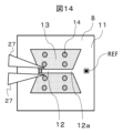
- the second control device 29, which is a control unit, moves the tweezers 27 by the tweezers drive mechanism 28 to a position where the lamella 12 can be gripped by the tweezers 27 by closing the tweezers 27 and the distance between the tweezers 27 and the lamella is the shortest within the range where the lamella 12 is not touched (a position immediately before the gripping position of the lamella 12 by the tweezers 27) according to the obtained distance between the lamella processing area B and the tweezers 27.
- Fig. 14 shows a conceptual diagram of the state where the tweezers 27 are moved to a position immediately before the gripping position of the lamella 12.
- Step S8 can be considered as a process of controlling the sample stage 26 on which the sample S is placed or the tweezers 27 so that the distance between the estimated surface shape of the inclined surface of the slope 13 (the position of the mark 14) and the position of the tweezers 27, which is the lamella transfer means, is reduced.
- the lamella lift-out device 2 which is a lamella extraction device, simultaneously measures the tweezers 27, which are the lamella transfer means, and the lamella processing area B of the lamella 12 using a scanning white light interference microscope 15, thereby obtaining the coordinates of the tweezers 27, the mark 14, and the upper surface of the lamella 12, and performs a process of controlling the tweezers 27 so that the distance between the tweezers 27 and the mark 14 is small and there is no contact between them.
- Step S9 Pick up sample
- the second control device 29 closes the tweezers 27 to grasp the lamella 12 and separates the lamella 12 from the sample S by moving or rotating the tweezers 27 in any direction using the tweezers drive mechanism 28.
- the second control device 29 After separating the lamella 12, the second control device 29 causes the tweezers 27 to move in the Z-axis direction using the tweezers drive mechanism 28 to a height where the tweezers 27 do not come into contact with the sample S.
- Step S10 Move the stage to the TEM mesh
- the second control device 29 drives the sample stage 26 and the tweezers driving mechanism 28 while referring to the microscope image obtained from the photodetector 24 so that the lamella 12 is located above the lamella installation position of the lamella holder 32 for TEM observation.
- Step S11 Place the sample (lamella 12) on the TEM mesh) Thereafter, the tweezers driving mechanism 28 is lowered in the Z-axis direction until the lamella 12 comes into contact with the lamella holder for TEM observation 32.
- the lamella lift-out device 2 which is a lamella extraction device, extracts (picks out) the lamella 12 from the sample S by a process of controlling the tweezers 27 so that the XY coordinates of the upper surface of the lamella 12 and the tip of the tweezers 27 (the part of the tweezers 27 that grips the lamella 12) coincide with each other, and transfers and mounts the lamella 12 on the lamella holder 32.
- the mesh 34 of the lamella holder 32 for TEM observation deforms due to contact with the object (lamella 12), the length of the optical path of the light L1 changes, and the intensity of the interference light L3 changes, causing a change in the microscope image output from the photodetector 24.
- a contact determination is made as to whether or not the lamella 12 and the mesh 34 have come into contact.
- the tweezers are released and the lamella 12 is placed on the lamella holder for TEM observation. This process completes the lamella lift-out.
- the operator moves the lamella holder 32 for TEM observation, which has lifted out the lamella 12, from the lamella lift-out device 2 to the TEM device 3. Then, the TEM observation of the lamella 12 is performed by the TEM device 3.
- a white light interference microscope 15 when a white light interference microscope 15 is used as an observation means, even if the inclined surface (surface of slope 13) produced by processing the lamella 12 is inclined more than the opening angle of the optical system of the photodetector 24, a surface (14S, 14S1, 14S2) different from the surface of slope 13 (also called the inclined surface or slope surface) is formed by forming a mark 14 on the surface of slope 13. Therefore, even if the reflected light L1R by the surface of slope 13 does not fall within the range of the maximum angle ⁇ , the surface 14S formed by the mark 14 is configured so that the reflected light L1R falls within the range of the maximum angle ⁇ .
- the second control device 29 is configured to be able to obtain information on the position of the lamella 12 (X-axis direction, Y-axis direction) and information on the Z-axis direction (height direction) of the slope 13 from the photodetector 24 of the white light interference microscope 15.
- the second control device 29 can grasp information on the position of the lamella 12 (X-axis direction, Y-axis direction) and information on the Z-axis direction (height direction) of the slope 13, so that the tweezers 27 used for picking up can be moved to a position just before the gripping position of the lamella 12 by the tweezers 27 without coming into contact with the sample processing area (lamella processing area of the lamella 12) B.
- the FIB-SEM composite device 1 is operated by an operator, but this operation can also be performed automatically by the FIB-SEM composite device 1 by registering the operation of each step in an operation control program for automatic operation control processing in the first control device 201.
- Example 1 In the configuration of Example 1, it is assumed that the operation of the lamella lift-out device 2 is performed by an operator, but this operation can also be performed by the lamella lift-out device 2 automatically by registering the operation of each step in an operation control program for automatic operation control processing in the second control device 29.
- an FIB-SEM composite device 1 that includes an irradiation optical system 4 for a focused ion beam 9 and an irradiation optical system 5 for an electron beam 10, but this is not limited to this.
- the white light interference microscope 15 uses a Linnik interferometer equipped with two objective lenses, a first objective lens 20 and a second objective lens 21, as an interference mechanism, but is not limited to this.
- a Michelson interferometer or a Mirau interferometer may also be used.
- the TEM observation lamella holder 32 is circular, but this is not limited to this.
- the grid frame 33 may be semicircular, etc.
- the marking process is performed using a sputtering process, but this is not limited to this.
- the marking process may also be performed using a deposition process.
- Example 1 mark processing was performed on the lamellar processing area B, but the object on which the mark 14 is applied is not limited to the slope 13.
- the mark 14 may be applied to the tweezers 27. As shown in FIG. 8, if the inclination of the tweezers 116 is greater than the measurement limit angle, the reflected light (L1R) from the tweezers cannot be detected. Therefore, by applying a mark 117 to the tweezers 116, the mark area can be measured with a microscope, and the position of the tweezers 116 can be grasped.
- the mark (14, 117) can be processed by sputtering or deposition.
- the present invention is not limited to the above-described embodiment, and can be modified, improved, etc. as appropriate.
- the material, shape, dimensions, values, form, number, location, etc. of each component in the above-described embodiment are arbitrary as long as they can achieve the present invention, and are not limited.
- FIB-SEM composite device 2 Lamella lift-out device 3: TEM device 7: Gas gun (deposition gas supply unit) 12: Lamella 13: Slope 14: Mark 15: White light interference microscope 25: Tube drive mechanism 26: Sample stage 27: Tweezers 114: Microscope image of mark 100: Lamella observation system
Landscapes
- Chemical & Material Sciences (AREA)
- Analytical Chemistry (AREA)
- Physics & Mathematics (AREA)
- Health & Medical Sciences (AREA)
- Life Sciences & Earth Sciences (AREA)
- Biochemistry (AREA)
- General Health & Medical Sciences (AREA)
- General Physics & Mathematics (AREA)
- Immunology (AREA)
- Pathology (AREA)
- Sampling And Sample Adjustment (AREA)
Priority Applications (4)
| Application Number | Priority Date | Filing Date | Title |
|---|---|---|---|
| PCT/JP2022/046768 WO2024134744A1 (ja) | 2022-12-20 | 2022-12-20 | ビーム装置、ラメラ抽出装置、ラメラ観察システムおよびラメラ作製方法 |
| KR1020257018638A KR20250108652A (ko) | 2022-12-20 | 2022-12-20 | 빔 장치, 라멜라 추출 장치, 라멜라 관찰 시스템 및 라멜라 제작 방법 |
| JP2024565423A JPWO2024134744A1 (https=) | 2022-12-20 | 2022-12-20 | |
| TW112149267A TWI891170B (zh) | 2022-12-20 | 2023-12-18 | 射線裝置,薄片抽出裝置,薄片觀察系統及薄片製作方法 |
Applications Claiming Priority (1)
| Application Number | Priority Date | Filing Date | Title |
|---|---|---|---|
| PCT/JP2022/046768 WO2024134744A1 (ja) | 2022-12-20 | 2022-12-20 | ビーム装置、ラメラ抽出装置、ラメラ観察システムおよびラメラ作製方法 |
Publications (1)
| Publication Number | Publication Date |
|---|---|
| WO2024134744A1 true WO2024134744A1 (ja) | 2024-06-27 |
Family
ID=91588151
Family Applications (1)
| Application Number | Title | Priority Date | Filing Date |
|---|---|---|---|
| PCT/JP2022/046768 Ceased WO2024134744A1 (ja) | 2022-12-20 | 2022-12-20 | ビーム装置、ラメラ抽出装置、ラメラ観察システムおよびラメラ作製方法 |
Country Status (4)
| Country | Link |
|---|---|
| JP (1) | JPWO2024134744A1 (https=) |
| KR (1) | KR20250108652A (https=) |
| TW (1) | TWI891170B (https=) |
| WO (1) | WO2024134744A1 (https=) |
Citations (4)
| Publication number | Priority date | Publication date | Assignee | Title |
|---|---|---|---|---|
| JP2002148159A (ja) * | 2000-11-06 | 2002-05-22 | Hitachi Ltd | 試料作製方法および試料作製装置 |
| JP2012178347A (ja) * | 2011-02-25 | 2012-09-13 | Fei Co | 荷電粒子ビーム・システムにおいて大電流モードと小電流モードとを高速に切り替える方法 |
| US20130323937A1 (en) * | 2012-05-29 | 2013-12-05 | Carl Zeiss Microscopy Gmbh | Combined Laser Processing System and Focused Ion Beam System |
| JP2016503890A (ja) * | 2012-12-31 | 2016-02-08 | エフ・イ−・アイ・カンパニー | 荷電粒子ビームを用いた傾斜ミリングまたは視射角ミリング操作用の基準マーク設計 |
Family Cites Families (3)
| Publication number | Priority date | Publication date | Assignee | Title |
|---|---|---|---|---|
| JP4037023B2 (ja) | 1999-11-18 | 2008-01-23 | エスアイアイ・ナノテクノロジー株式会社 | 透過電子顕微鏡用試料の切り込み加工方法及び作成方法 |
| JP6541161B2 (ja) * | 2017-11-17 | 2019-07-10 | 株式会社日立ハイテクサイエンス | 荷電粒子ビーム装置 |
| JP7389817B2 (ja) * | 2019-11-20 | 2023-11-30 | 株式会社日立ハイテク | ラメラの作製方法、解析システムおよび試料の解析方法 |
-
2022
- 2022-12-20 JP JP2024565423A patent/JPWO2024134744A1/ja active Pending
- 2022-12-20 KR KR1020257018638A patent/KR20250108652A/ko active Pending
- 2022-12-20 WO PCT/JP2022/046768 patent/WO2024134744A1/ja not_active Ceased
-
2023
- 2023-12-18 TW TW112149267A patent/TWI891170B/zh active
Patent Citations (4)
| Publication number | Priority date | Publication date | Assignee | Title |
|---|---|---|---|---|
| JP2002148159A (ja) * | 2000-11-06 | 2002-05-22 | Hitachi Ltd | 試料作製方法および試料作製装置 |
| JP2012178347A (ja) * | 2011-02-25 | 2012-09-13 | Fei Co | 荷電粒子ビーム・システムにおいて大電流モードと小電流モードとを高速に切り替える方法 |
| US20130323937A1 (en) * | 2012-05-29 | 2013-12-05 | Carl Zeiss Microscopy Gmbh | Combined Laser Processing System and Focused Ion Beam System |
| JP2016503890A (ja) * | 2012-12-31 | 2016-02-08 | エフ・イ−・アイ・カンパニー | 荷電粒子ビームを用いた傾斜ミリングまたは視射角ミリング操作用の基準マーク設計 |
Also Published As
| Publication number | Publication date |
|---|---|
| JPWO2024134744A1 (https=) | 2024-06-27 |
| TW202441563A (zh) | 2024-10-16 |
| KR20250108652A (ko) | 2025-07-15 |
| TWI891170B (zh) | 2025-07-21 |
Similar Documents
| Publication | Publication Date | Title |
|---|---|---|
| US10825651B2 (en) | Automated TEM sample preparation | |
| TWI575549B (zh) | 加工程序中的晶片內及晶片間電性分析與使用線內奈米探測的製程控制 | |
| JP5410286B2 (ja) | S/temのサンプルを作成する方法およびサンプル構造 | |
| KR102056507B1 (ko) | 하전 입자 빔 장치 및 시료 관찰 방법 | |
| JP5719494B2 (ja) | 電子ビームを用いた表面下の画像化 | |
| KR102366149B1 (ko) | 자동화된 s/tem 획득 및 계측을 위해 이미 알고 있는 형상의 박편을 사용하는 패턴 매칭 | |
| US10978272B2 (en) | Measurement and endpointing of sample thickness | |
| JP2010507781A5 (https=) | ||
| CN110335800B (zh) | 带电粒子束装置 | |
| JP2010507782A5 (https=) | ||
| TWI600878B (zh) | Height measuring device, and charged particle beam device | |
| US20140312224A1 (en) | Pattern inspection method and pattern inspection apparatus | |
| WO2024134744A1 (ja) | ビーム装置、ラメラ抽出装置、ラメラ観察システムおよびラメラ作製方法 | |
| WO2025088205A2 (en) | Computer-implemented method and apparatus for processing a sample with a nanomanipulator | |
| CN103824798A (zh) | 自动化样品定向 | |
| JPH09283073A (ja) | イオンビーム照射装置 | |
| JP7425231B2 (ja) | 試料片移設装置 | |
| WO2026088361A1 (ja) | ラメラ移設装置およびラメラの移設方法 | |
| JP2014123480A (ja) | 荷電粒子線装置 | |
| KR20140136316A (ko) | 시료 제작 장치 및 그를 이용한 시료 제작 방법 |
Legal Events
| Date | Code | Title | Description |
|---|---|---|---|
| 121 | Ep: the epo has been informed by wipo that ep was designated in this application |
Ref document number: 22969133 Country of ref document: EP Kind code of ref document: A1 |
|
| WWE | Wipo information: entry into national phase |
Ref document number: 1020257018638 Country of ref document: KR |
|
| WWE | Wipo information: entry into national phase |
Ref document number: 2024565423 Country of ref document: JP |
|
| WWP | Wipo information: published in national office |
Ref document number: 1020257018638 Country of ref document: KR |
|
| NENP | Non-entry into the national phase |
Ref country code: DE |
|
| 122 | Ep: pct application non-entry in european phase |
Ref document number: 22969133 Country of ref document: EP Kind code of ref document: A1 |