WO2024134726A1 - エレベータ装置 - Google Patents
エレベータ装置 Download PDFInfo
- Publication number
- WO2024134726A1 WO2024134726A1 PCT/JP2022/046688 JP2022046688W WO2024134726A1 WO 2024134726 A1 WO2024134726 A1 WO 2024134726A1 JP 2022046688 W JP2022046688 W JP 2022046688W WO 2024134726 A1 WO2024134726 A1 WO 2024134726A1
- Authority
- WO
- WIPO (PCT)
- Prior art keywords
- car
- landing
- door
- pair
- interlock device
- Prior art date
- Legal status (The legal status is an assumption and is not a legal conclusion. Google has not performed a legal analysis and makes no representation as to the accuracy of the status listed.)
- Ceased
Links
Images




Classifications
-
- B—PERFORMING OPERATIONS; TRANSPORTING
- B66—HOISTING; LIFTING; HAULING
- B66B—ELEVATORS; ESCALATORS OR MOVING WALKWAYS
- B66B13/00—Doors, gates, or other apparatus controlling access to, or exit from, cages or lift well landings
- B66B13/02—Door or gate operation
- B66B13/12—Arrangements for effecting simultaneous opening or closing of cage and landing doors
-
- B—PERFORMING OPERATIONS; TRANSPORTING
- B66—HOISTING; LIFTING; HAULING
- B66B—ELEVATORS; ESCALATORS OR MOVING WALKWAYS
- B66B13/00—Doors, gates, or other apparatus controlling access to, or exit from, cages or lift well landings
- B66B13/02—Door or gate operation
- B66B13/14—Control systems or devices
- B66B13/16—Door or gate locking devices controlled or primarily controlled by condition of cage, e.g. movement or position
- B66B13/18—Door or gate locking devices controlled or primarily controlled by condition of cage, e.g. movement or position without manually-operable devices for completing locking or unlocking of doors
-
- B—PERFORMING OPERATIONS; TRANSPORTING
- B66—HOISTING; LIFTING; HAULING
- B66B—ELEVATORS; ESCALATORS OR MOVING WALKWAYS
- B66B13/00—Doors, gates, or other apparatus controlling access to, or exit from, cages or lift well landings
- B66B13/02—Door or gate operation
- B66B13/14—Control systems or devices
- B66B13/16—Door or gate locking devices controlled or primarily controlled by condition of cage, e.g. movement or position
- B66B13/18—Door or gate locking devices controlled or primarily controlled by condition of cage, e.g. movement or position without manually-operable devices for completing locking or unlocking of doors
- B66B13/20—Lock mechanisms actuated mechanically by abutments or projections on the cages
-
- B—PERFORMING OPERATIONS; TRANSPORTING
- B66—HOISTING; LIFTING; HAULING
- B66B—ELEVATORS; ESCALATORS OR MOVING WALKWAYS
- B66B5/00—Applications of checking, fault-correcting, or safety devices in elevators
Definitions
- This disclosure relates to elevator equipment.
- the interlock device has a hasp, a latch, a fixed interlock roller, and a movable interlock roller.
- the fixed interlock roller and the movable interlock roller are sandwiched by a vane mechanism.
- the movable interlock roller moves along an arc centered on the fixed interlock roller, and the latch is released from the hasp, unlocking the interlock device (see, for example, Patent Document 1).
- the floor height of one landing floor may differ from the floor height of other landing floors, which may result in differences in the height dimensions of the landing entrances.
- the vane mechanism limits the zone in which the interlock device is permitted to be unlocked, which limits the installation location of the interlock device.
- This disclosure has been made to solve the problems described above, and aims to provide an elevator system that allows for greater freedom in the installation location of the interlock device.
- the elevator device disclosed herein is provided with a car entrance and includes a pair of car doors that are provided on a car that moves up and down in a hoistway and that open and close the car entrance and exit by mechanically interlocking with each other and moving in opposite directions, a pair of first landing doors that open and close a first landing entrance and exit by mechanically interlocking with each other and moving in opposite directions, a pair of second landing doors that open and close a second landing entrance and exit provided on a landing floor different from the first landing entrance and exit by mechanically interlocking with each other and moving in opposite directions, and are provided above the first landing entrance and exit,
- the system is equipped with a first interlock device that prevents the opening of the pair of first landing doors, a second interlock device that is provided above the second landing entrance and is arranged in the left-right opposite direction to the first interlock device and prevents the opening of the pair of second landing doors, a first unlocking mechanism that is provided on one of the pair of car doors and unlocks the first interlock device when the pair of
- the elevator device disclosed herein allows for greater freedom in the installation location of the interlock device.
- FIG. 1 is a schematic configuration diagram showing an elevator device according to a first embodiment.
- FIG. 2 is a front view of a first landing door device in the elevator apparatus of FIG. 1 as viewed from the hoistway side.
- FIG. 2 is a front view of a second landing door device in the elevator apparatus of FIG. 1 as viewed from the hoistway side.
- FIG. 2 is a front view of the car door device in the elevator system of FIG. 1 as viewed from the landing side.
- 5 is an explanatory diagram illustrating a schematic positional relationship between the first interlock device of FIG. 2 and the first and second unlocking mechanisms of FIG. 4 .
- FIG. 5 is an explanatory diagram illustrating a schematic positional relationship between the second interlock device of FIG. 3 and the first and second unlocking mechanisms of FIG.
- FIG. FIG. 11 is a front view of a car door device in an elevator apparatus according to a second embodiment, as viewed from the landing side.
- FIG. 11 is a front view of a first landing door device in an elevator apparatus according to a second embodiment, as viewed from the hoistway side.
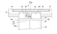
- FIG. 9 is an enlarged front view showing a main part of FIG. 8 .
- 9 is an explanatory diagram showing a schematic positional relationship between the first unlocking mechanism and the second unlocking mechanism in FIG. 7 and the first interlock device and the auxiliary roller in FIG. 8 .
- FIG. 11 is an explanatory diagram illustrating a schematic positional relationship between the first unlocking mechanism and the second unlocking mechanism, and the second interlock device and the auxiliary roller when the first interlock device is used as a car door unlocking interlock device;
- FIG. 13 is an explanatory diagram showing an example in which a maintenance unlocking member is installed on the top floor.
- FIG. 11 is a front view of a landing door device for the lowest floor in an elevator apparatus according to embodiment 3, as viewed from the hoistway side.
- Fig. 1 is a schematic diagram showing an elevator apparatus according to embodiment 1.
- a support beam 2 is provided at the top of a hoistway 1.
- a hoisting machine 3 is supported on the support beam 2.
- the hoisting machine 3 has a hoisting machine main body 4 and a drive sheave 5.
- the hoist body 4 has a hoist motor (not shown) and a hoist brake (not shown).
- the hoist motor rotates the drive sheave 5.
- the hoist brake keeps the drive sheave 5 stationary.
- the hoist brake also brakes the rotation of the drive sheave 5.
- a suspension body (not shown) is wrapped around the drive sheave 5.
- the suspension body is made up of multiple ropes or multiple belts.
- a car 6 and a counterweight (not shown).
- the car 6 and the counterweight are suspended by a suspension body, and move up and down inside the hoistway 1 by rotating the drive sheave 5.
- Multiple guide rails (not shown) are installed in the elevator shaft 1.
- the multiple guide rails guide the elevator car 6 and the counterweight as they ascend and descend.
- the support beam 2 is supported by two or more of the multiple guide rails.
- a car entrance 6a is provided on the front of the car 6.
- the car 6 is also provided with a car door device.
- the car door device has a pair of car doors, a right car door 7a and a left car door 7b.
- the right car door 7a is a car door located on the right side when looking at the car entrance 6a from the landing.
- the left car door 7b is a car door located on the left side when looking at the car entrance 6a from the landing.
- the right car door 7a and the left car door 7b are mechanically linked to each other and operate in opposite directions to open and close the car entrance 6a.
- a number of landing entrances are provided between the multiple landing floors and the elevator 1.
- the multiple landing entrances include at least one first landing entrance 10a and at least one second landing entrance 10b.
- the second landing entrance 10b is provided on a landing floor different from the first landing entrance 10a.
- the landing entrances at the multiple landing floors excluding the lowest floor are each a first landing entrance 10a. Also, the landing entrance at the lowest floor is a second landing entrance 10b.
- the height dimension h1 of each first landing entrance 10a and the height dimension h2 of the second landing entrance 10b are different from each other.
- the height dimension h2 of the second landing entrance 10b is greater than the height dimension h1 of each first landing entrance 10a.
- the height dimension of the landing entrance is the vertical dimension from the landing floor to the top end of the landing entrance.
- a first landing door device is provided on each of the multiple landing floors where the first landing entrance/exit 10a is provided.
- Each first landing door device has a pair of first landing doors, a first right landing door 8a and a first left landing door 8b.
- the first right landing door 8a is a landing door located on the right side when the first landing entrance/exit 10a is viewed from the landing.
- the first left landing door 8b is a landing door located on the left side when the first landing entrance/exit 10a is viewed from the landing.
- first right landing door 8a and the first left landing door 8b operate in opposite directions in mechanical interlocking relation to each other to open and close the corresponding first landing entrance/exit 10a. Also, in each first landing door device, the first right landing door 8a and the first left landing door 8b operate to open and close in interlocking relation to the right car door 7a and the left car door 7b when the car 6 lands on the floor.
- a second landing door device is provided on the landing floor where the second landing entrance 10b is provided.
- the second landing door device has a pair of second landing doors, a second right landing door 9a and a second left landing door 9b.
- the second right landing door 9a is a landing door located on the right side when looking at the second landing entrance 10b from the landing.
- the second left landing door 9b is a landing door located on the left side when looking at the second landing entrance 10b from the landing.
- the second right landing door 9a and the second left landing door 9b are mechanically linked to each other and operate in opposite directions to open and close the second landing entrance 10b.
- the second right landing door 9a and the second left landing door 9b are linked to the right car door 7a and the left car door 7b to open and close when the car 6 lands on the floor.
- FIG. 2 is a front view of the first landing door device in the elevator system of FIG. 1, as seen from the hoistway 1 side.
- the first landing door device is seen from the opposite side to the landing, so the first right landing door 8a is located on the left side, and the first left landing door 8b is located on the right side.
- a landing door frame 11 is fixed above the first landing entrance 10a.
- a landing door rail 12 is provided on the landing door frame 11.
- the landing door rail 12 is parallel to the width direction of the first landing entrance 10a and is horizontal.
- the width direction of the first landing entrance 10a is parallel to the opening and closing operation direction of the first right landing door 8a and the first left landing door 8b, and is the left-right direction in Figure 2.
- a first pulley 13 is provided at a first end of the landing door frame 11 in the width direction of the first landing entrance 10a.
- a second pulley 14 is provided at a second end of the landing door frame 11 in the width direction of the first landing entrance 10a.
- An endless interlocking rope 15 is wound around the first pulley 13 and the second pulley 14.
- the first right-side landing door 8a and the first left-side landing door 8b each have a landing door panel 16 and a landing door hanger 17. Each landing door hanger 17 is fixed to the top of the corresponding landing door panel 16.
- Each landing door hanger 17 is provided with a plurality of landing door rollers 18. Each landing door roller 18 moves while rolling on the landing door rail 12 when the first right landing door 8a and the first left landing door 8b are opened or closed. The first right landing door 8a and the first left landing door 8b are suspended from the landing door rail 12 and open or close along the landing door rail 12.
- the first right-side landing door 8a is connected to the upper part of the interlocking rope 15 via a first landing door connecting fitting 19.
- the first left-side landing door 8b is connected to the lower part of the interlocking rope 15 via a second landing door connecting fitting 20.
- a first interlock device 21a is provided between the first right-side landing door 8a and the landing door frame 11. That is, the first interlock device 21a is provided above the first landing entrance 10a. The first interlock device 21a prevents the first right-side landing door 8a and the first left-side landing door 8b from opening.
- the first interlock device 21a has a latch 22, a latch 23, a fixed interlock roller 24, and a movable interlock roller 25.
- the latch 22 is fixed to the landing door frame 11.
- the latch 23 is rotatably attached to the landing door hanger 17 of the first right landing door 8a.
- the tip of the latch 23 gets caught on the latch 22, thereby preventing the first right landing door 8a and the first left landing door 8b from opening.
- the fixed interlock roller 24 is arranged coaxially with the rotation axis of the latch 23.
- the movable interlock roller 25 is rotatably attached to the latch 23.
- the latch 23 and the movable interlock roller 25 move along an arc centered on the rotation axis of the latch 23.
- Figure 3 is a front view of the second landing door device in the elevator system of Figure 1, as seen from the hoistway 1 side.
- the second landing door device is seen from the opposite side to the landing, so the second right landing door 9a is located on the left side, and the second left landing door 9b is located on the right side.
- the basic configuration of the second landing door device is the same as that of the first landing door device.
- the second right landing door 9a and the second left landing door 9b each have a landing door panel 16 and a landing door hanger 17.
- the vertical dimension of each landing door panel 16 in the second landing door device is larger than the vertical dimension of each landing door panel 16 in the first landing door device.
- the second landing entrance 10b similar to the first landing door device, there are provided a landing door frame 11, a landing door rail 12, a first pulley 13, a second pulley 14, and an interlocking rope 15.
- the second right-side landing door 9a is connected to the upper part of the interlocking rope 15 via a first landing door connecting fitting 19.
- the second left-side landing door 9b is connected to the lower part of the interlocking rope 15 via a second landing door connecting fitting 20.
- a second interlock device 21b is provided between the second left-side landing door 9b and the landing door frame 11. That is, the second interlock device 21b is provided above the second landing entrance 10b. The second interlock device 21b prevents the second right-side landing door 9a and the second left-side landing door 9b from opening.
- the second interlock device 21b like the first interlock device 21a, has a latch 22, a latch 23, a fixed interlock roller 24, and a movable interlock roller 25.
- the second interlock device 21b is arranged in the opposite left-right direction to the first interlock device 21a when viewed from the elevator shaft 1 side.
- the second interlock device 21b is arranged symmetrically to the first interlock device 21a with respect to the center of the width of the first landing entrance 10a and the second landing entrance 10b.
- Figure 4 is a front view of the car door device in the elevator device of Figure 1, viewed from the landing side.
- a car door frame 31 is fixed to the upper part of the car entrance 6a.
- a car door rail 32 is provided on the car door frame 31.
- the car door rail 32 is parallel to the width direction of the car entrance 6a and is horizontal.
- the width direction of the car entrance 6a is parallel to the opening and closing operation direction of the right car door 7a and the left car door 7b, and is the left-right direction in Figure 4.
- the right car door 7a and the left car door 7b each have a car door panel 33 and a car door hanger 34.
- Each car door hanger 34 is fixed to the upper part of the corresponding car door panel 33.
- the right car door 7a and the left car door 7b are suspended from a car door rail 32 and open and close along the car door rail 32.
- the car door frame 31 is provided with a car door interlocking mechanism (not shown) and a door motor (not shown).
- the car door interlocking mechanism mechanically interlocks the right car door 7a and the left car door 7b with each other.
- the output of the door motor is transmitted to the right car door 7a and the left car door 7b via the car door interlocking mechanism. This causes the right car door 7a and the left car door 7b to open and close.
- the right car door 7a which is one of the pair of car doors, is provided with a first unlocking mechanism 41.
- the first unlocking mechanism 41 unlocks the first interlock device 21a when the right car door 7a and the left car door 7b are opened at each of the multiple landing floors where the first landing entrance/exit 10a is provided.
- the first unlocking mechanism 41 has a first door stopper side vane 42 and a first door pocket side vane 43.
- the first door stopper side vane 42 and the first door pocket side vane 43 are provided on the car door panel 33 of the right car door 7a.
- the first door pocket side vane 43 can move in the width direction of the car entrance 6a relative to the right car door 7a.
- the distance between the first door stop side vane 42 and the first door pocket side vane 43 changes as the first door pocket side vane 43 moves relative to the right car door 7a.
- the car door frame 31 and the right car door 7a are provided with a first operating mechanism 44.
- the first operating mechanism 44 moves the first door pocket side vane 43 relative to the right car door 7a when the right car door 7a is opened or closed.
- the first unlocking mechanism 41 sandwiches the fixed interlock roller 24 and the movable interlock roller 25 of the first landing door device between the first door striker vane 42 and the first door pocket vane 43. As a result, the first unlocking mechanism 41 rotates the latch 23, unlocking the first interlock device 21a and moving the first right landing door 8a together with the right car door 7a.
- the other of the pair of car doors, the left car door 7b, is provided with a second unlocking mechanism 45.
- the second unlocking mechanism 45 unlocks the second interlock device 21b when the right car door 7a and the left car door 7b are opened at the landing floor where the second landing entrance 10b is located.
- the installation height of the second unlocking mechanism 45 relative to the car entrance 6a is different from the installation height of the first unlocking mechanism 41 relative to the car entrance 6a. Specifically, the installation position of the second unlocking mechanism 45 relative to the car entrance 6a is higher than the installation position of the first unlocking mechanism 41 relative to the car entrance 6a.
- the second unlocking mechanism 45 has a second door stopper side vane 46 and a second door pocket side vane 47.
- the second door stopper side vane 46 and the second door pocket side vane 47 are provided on the car door panel 33 of the left car door 7b.
- the second door pocket side vane 47 can move in the width direction of the car entrance 6a relative to the left car door 7b.
- the distance between the second door stop side vane 46 and the second door pocket side vane 47 changes as the second door pocket side vane 47 moves relative to the left car door 7b.
- the car door frame 31 and the left car door 7b are provided with a second operating mechanism 48.
- the second operating mechanism 48 moves the second door pocket vane 47 when the left car door 7b is opened or closed.
- the second unlocking mechanism 45 sandwiches the fixed interlock roller 24 and the movable interlock roller 25 of the second landing door device between the second door stopper vane 46 and the second door pocket vane 47. As a result, the second unlocking mechanism 45 rotates the latch 23, unlocking the second interlock device 21b and moving the second left landing door 9b together with the left car door 7b.
- FIG. 5 is an explanatory diagram that shows a schematic positional relationship between the first interlock device 21a in FIG. 2 and the first unlocking mechanism 41 and second unlocking mechanism 45 in FIG. 4.
- the first unlocking mechanism 41 faces the first interlock device 21a.
- FIG. 6 is an explanatory diagram that shows a schematic diagram of the positional relationship between the second interlock device 21b in FIG. 3 and the first unlocking mechanism 41 and the second unlocking mechanism 45 in FIG. 4.
- the second unlocking mechanism 45 faces the second interlock device 21b.
- the second interlock device 21b is disposed in the left-right opposite orientation to the first interlock device 21a.
- a first unlocking mechanism 41 that unlocks the first interlock device 21a is provided on the right car door 7a, which is one of the pair of car doors.
- a second unlocking mechanism 45 that unlocks the second interlock device 21b is provided on the left car door 7b, which is the other of the pair of car doors.
- the installation positions of the first interlock device 21a and the second interlock device 21b can be changed depending on the landing floor, improving the degree of freedom in the installation positions of the first interlock device 21a and the second interlock device 21b.
- the installation height of the second unlocking mechanism 45 relative to the car entrance 6a is different from the installation height of the first unlocking mechanism 41 relative to the car entrance 6a. This makes it possible to relax restrictions on the difference between the height dimension h1 of the first landing entrance 10a and the height dimension h2 of the second landing entrance 10b. In other words, it is possible to relax restrictions on the difference in height dimension between multiple different landing entrances.
- first interlock device 21a and the second interlock device 21b are disposed outside the landing door panel 16. Therefore, even if the landing door panel 16 is provided with a glass window, the first interlock device 21a and the second interlock device 21b cannot be seen from the landing.
- Embodiment 2. 7 is a front view of a car door device in an elevator system according to embodiment 2, seen from the hall side.
- a car door locking mechanism 51 is provided in the car 6.
- the car door locking mechanism 51 prevents the right car door 7a and the left car door 7b from opening when the car 6 is located outside the door opening area.
- the door opening area is an area in which the right car door 7a and the left car door 7b are permitted to open when the car 6 lands on the floor during the lifting or lowering process.
- the car door locking mechanism 51 also allows the right car door 7a and the left car door 7b to open when the car 6 is located within the door opening area.
- the car door locking mechanism 51 has a fixed locking element 52 and an L-shaped rotating member 53.
- the fixed locking element 52 is fixed to the car door panel 33 of the right car door 7a.
- the fixed locking element 52 has a groove 52a.
- the middle part of the rotating member 53 is rotatably connected to the door panel 33 of the left car door 7b.
- the lower end part of the rotating member 53 is rotatably connected to the second door stop side vane 46.
- a lock pin 53a is provided at the upper end part of the rotating member 53.
- the fixed interlock roller 24 and the movable interlock roller 25 of the second interlock device 21b are between the second door-stop vane 46 and the second door pocket vane 47.
- the rotation of the rotating member 53 in the clockwise direction in FIG. 7 is restricted, the lock pin 53a does not enter the groove 52a, and the opening operation is permitted.
- the car door unlocking interlock device in embodiment 2 is the second interlock device 21b.
- the car door unlocking mechanism is the second unlocking mechanism 45.
- the car door unlocking mechanism is the unlocking mechanism that corresponds to the car door unlocking interlock device, either the first unlocking mechanism 41 or the second unlocking mechanism 45.
- the car door locking mechanism 51 allows the right car door 7a and the left car door 7b to open as the second unlocking mechanism 45 hits the second interlock device 21b.
- FIG. 8 is a front view of the first landing door device in an elevator system according to embodiment 2, as seen from the hoistway side.
- FIG. 9 is a front view showing an enlarged view of the main part of FIG. 8.
- the landing door frame 11 is provided with an auxiliary guide body 61.
- the auxiliary guide body 61 is provided with a movable body 62.
- the movable body 62 is guided by the auxiliary guide body 61 and can move in the width direction of the first landing entrance/exit 10a.
- the movable body 62 is provided with an auxiliary unlocking member 63.
- the auxiliary unlocking member 63 is provided at a position corresponding to the second unlocking mechanism 45.
- the auxiliary unlocking member 63 can move together with the movable body 62 along the auxiliary guide body 61 in a direction parallel to the opening and closing direction of the right car door 7a and the left car door 7b.
- the auxiliary unlocking member 63 is a roller similar to the fixed side interlock roller 24.
- the auxiliary unlocking member 63 When the first right-side landing door 8a and the first left-side landing door 8b are in the fully closed position, the auxiliary unlocking member 63 is in the standby position shown in Figures 8 and 9. When the auxiliary unlocking member 63 is in the standby position, the vertical line C1 passing through the center of the auxiliary unlocking member 63 passes through the center of the fixed interlock roller 24 in the second landing door device.
- FIG. 10 is an explanatory diagram that shows a schematic positional relationship between the first unlocking mechanism 41 and the second unlocking mechanism 45 in FIG. 7 and the first interlock device 21a and the auxiliary unlocking member 63 in FIG. 8.
- the car door locking mechanism 51 allows the right car door 7a and the left car door 7b to open as the second unlocking mechanism 45 hits the auxiliary unlocking member 63.
- an auxiliary unlocking member 63 is provided at the landing floor where the first interlock device 21a, which is not a car door unlocking interlock device, is provided.
- the auxiliary unlocking member 63 is also provided at a position corresponding to the second unlocking mechanism 45.
- the car door locking mechanism 51 allows the right car door 7a and the left car door 7b to open even when the second unlocking mechanism 45 hits the auxiliary unlocking member 63.
- the second interlock device 21b is a car door unlocking interlock device
- the second unlocking mechanism 45 is a car door unlocking mechanism
- the first interlock device 21a may be a car door unlocking interlock device
- the first unlocking mechanism 41 may be a car door unlocking mechanism.
- the car door locking mechanism 51 is installed symmetrically with respect to the center of the width of the car entrance 6a, and at a lower position than the position in FIG. 7, in comparison with the configuration in FIG. 7.
- FIG. 11 is an explanatory diagram that shows a schematic diagram of the positional relationship between the first unlocking mechanism 41 and the second unlocking mechanism 45, and the second interlocking device 21b and the auxiliary unlocking member 63 when the first interlocking device 21a is used as a car door unlocking interlocking device.
- the auxiliary unlocking member 63 is provided on the second right-side landing door 9a at each landing floor where a second interlock device 21b that is not a car door unlocking interlock device is provided.
- the auxiliary unlocking member 63 is also provided at a position on the second right-side landing door 9a that corresponds to the second unlocking mechanism 45.
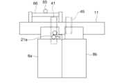
- a maintenance unlocking member 65 and a maintenance guide body 66 may be provided above the first landing entrance 10a on the top floor in the elevator 1.
- the maintenance unlocking member 65 is guided by the maintenance guide body 66 and can move in a direction parallel to the opening and closing direction of the right car door 7a and the left car door 7b.
- the maintenance unlocking member 65 is a roller similar to the auxiliary unlocking member 63.
- first unlocking mechanism 41 may be extended upward so that the vertical dimension of the first unlocking mechanism 41 is greater than the vertical dimension of the second unlocking mechanism 45.
- the worker moves the maintenance unlocking member 65 to a position directly above the first unlocking mechanism 41 before moving the car 6 above the door-opening area. After this, the car 6 is moved above the top floor, so that the maintenance unlocking member 65 faces the first unlocking mechanism 41.
- car 6 becomes unable to move during maintenance work on the car, the worker moves into car 6 from the ceiling rescue exit and manually moves right car door 7a and left car door 7b in the opening direction.
- the first unlocking mechanism 41 hits the maintenance unlocking member 65, allowing the right car door 7a and the left car door 7b to open.
- the car door locking mechanism 51 allows the right car door 7a and the left car door 7b to open even when the first unlocking mechanism 41 hits the maintenance unlocking member 65.
- the worker After moving the right car door 7a and the left car door 7b to a certain extent in the opening direction, the worker uses a door fixing tool (not shown) to prevent the right car door 7a and the left car door 7b from moving in the closing direction. After this, the worker manually unlocks the first interlock device 21a and manually moves the first right landing door 8a and the first left landing door 8b in the opening direction, allowing the worker to escape to the landing.
- auxiliary unlocking member 63 and the maintenance unlocking member 65 are not limited to rollers.
- the configuration of the car door locking mechanism 51 is not limited to the above configuration.
- Embodiment 3 Next, an elevator apparatus according to embodiment 3 will be described.
- the height dimensions of the landing entrances at all landing floors are the same or the difference in height dimensions of the landing entrances is small, so the installation height of the first unlocking mechanism 41 relative to the car entrance 6a is the same as the installation height of the second unlocking mechanism 45 relative to the car entrance 6a.
- FIG. 13 is a front view of the landing door device for the lowest floor in an elevator system according to embodiment 3, as seen from the hoistway 1 side.
- the second interlock device 21b installed on the lowest floor is equipped with a pit unlocking mechanism 26.
- the pit unlocking mechanism 26 has, for example, a flexible operating member. For example, a wire or rope is used as the operating member.
- the operating member is connected to the latch 23.
- a pit ladder (not shown) is installed in the pit of the elevator shaft 1.
- the pit ladder is used by workers to move between the lowest floor landing and the pit.
- the second interlock device 21b is manually unlocked by the worker operating the operating member from the pit or the pit ladder.
- the pit unlocking mechanism 26 is installed on the landing door on the side where the latch 23 is installed. Also, the pit ladder is installed below the landing door on which the pit unlocking mechanism 26 is installed.
- the layout of the elevator system may mean that it is not possible to install a pit ladder below the landing door on the side where the latches 23 are installed. In that case, the pit ladder and the pit unlocking mechanism 26 will be separated to the left and right, making it difficult to operate the pit unlocking mechanism 26 from the pit ladder.
- the car 6 is provided with a first unlocking mechanism 41 and a second unlocking mechanism 45, and the second interlock device 21b is disposed on the opposite side to each of the first interlock devices 21a at the other landing floors.
- the height dimensions of different landing entrances and exits may be different.
- the number of landing entrances with large height dimensions is not particularly limited and may be two or more.
- the number of landing entrances with small height dimensions is not particularly limited.
- the height dimension of the landing entrance on the lowest floor may be smaller than the height dimensions of landing entrances on floors other than the lowest floor.
- the number of height dimension patterns of the landing entrance may be three or more.
- the structure and size of the first interlock device do not have to be the same as the structure and size of the second interlock device.
- the car door device and the landing door device may be a single-leaf door device.
- the number of door panels in each of the car door device and the landing door device may be one or three or more.
- the layout of the elevator system is not limited to the layout shown in FIG. 1.
- the hoist 3 may be installed at a location other than the top of the hoistway 1.
- the elevator system may also be an elevator system with a machine room, a double-deck elevator, a one-shaft multi-car elevator, etc.
- the one-shaft multi-car system is a system in which an upper car and a lower car located directly below the upper car each independently ascend and descend in a common elevator shaft.
Landscapes
- Engineering & Computer Science (AREA)
- Automation & Control Theory (AREA)
- Mechanical Engineering (AREA)
- Elevator Door Apparatuses (AREA)
Priority Applications (3)
| Application Number | Priority Date | Filing Date | Title |
|---|---|---|---|
| JP2024565409A JP7843861B2 (ja) | 2022-12-19 | 2022-12-19 | エレベータ装置 |
| CN202280099745.0A CN120322403A (zh) | 2022-12-19 | 2022-12-19 | 电梯装置 |
| PCT/JP2022/046688 WO2024134726A1 (ja) | 2022-12-19 | 2022-12-19 | エレベータ装置 |
Applications Claiming Priority (1)
| Application Number | Priority Date | Filing Date | Title |
|---|---|---|---|
| PCT/JP2022/046688 WO2024134726A1 (ja) | 2022-12-19 | 2022-12-19 | エレベータ装置 |
Publications (1)
| Publication Number | Publication Date |
|---|---|
| WO2024134726A1 true WO2024134726A1 (ja) | 2024-06-27 |
Family
ID=91588142
Family Applications (1)
| Application Number | Title | Priority Date | Filing Date |
|---|---|---|---|
| PCT/JP2022/046688 Ceased WO2024134726A1 (ja) | 2022-12-19 | 2022-12-19 | エレベータ装置 |
Country Status (3)
| Country | Link |
|---|---|
| JP (1) | JP7843861B2 (https=) |
| CN (1) | CN120322403A (https=) |
| WO (1) | WO2024134726A1 (https=) |
Citations (5)
| Publication number | Priority date | Publication date | Assignee | Title |
|---|---|---|---|---|
| JPS5293044A (en) * | 1976-01-30 | 1977-08-05 | Hitachi Ltd | Elevator |
| JPH0812228A (ja) * | 1994-06-30 | 1996-01-16 | Mitsubishi Electric Corp | エレベーター装置 |
| WO2010125650A1 (ja) * | 2009-04-28 | 2010-11-04 | 三菱電機株式会社 | エレベータのドア装置 |
| WO2016059685A1 (ja) * | 2014-10-15 | 2016-04-21 | 三菱電機株式会社 | エレベータのかごドア装置 |
| CN111170127A (zh) * | 2020-01-19 | 2020-05-19 | 宁波宏大电梯有限公司 | 一种适配两种不同高度的门洞的电梯结构 |
-
2022
- 2022-12-19 WO PCT/JP2022/046688 patent/WO2024134726A1/ja not_active Ceased
- 2022-12-19 CN CN202280099745.0A patent/CN120322403A/zh active Pending
- 2022-12-19 JP JP2024565409A patent/JP7843861B2/ja active Active
Patent Citations (5)
| Publication number | Priority date | Publication date | Assignee | Title |
|---|---|---|---|---|
| JPS5293044A (en) * | 1976-01-30 | 1977-08-05 | Hitachi Ltd | Elevator |
| JPH0812228A (ja) * | 1994-06-30 | 1996-01-16 | Mitsubishi Electric Corp | エレベーター装置 |
| WO2010125650A1 (ja) * | 2009-04-28 | 2010-11-04 | 三菱電機株式会社 | エレベータのドア装置 |
| WO2016059685A1 (ja) * | 2014-10-15 | 2016-04-21 | 三菱電機株式会社 | エレベータのかごドア装置 |
| CN111170127A (zh) * | 2020-01-19 | 2020-05-19 | 宁波宏大电梯有限公司 | 一种适配两种不同高度的门洞的电梯结构 |
Also Published As
| Publication number | Publication date |
|---|---|
| CN120322403A (zh) | 2025-07-15 |
| JP7843861B2 (ja) | 2026-04-10 |
| JPWO2024134726A1 (https=) | 2024-06-27 |
Similar Documents
| Publication | Publication Date | Title |
|---|---|---|
| JP5940220B2 (ja) | エレベータのかごドアロック装置 | |
| CN107074502B (zh) | 电梯的轿厢门装置 | |
| JP6704068B2 (ja) | エレベーター装置 | |
| JP2015037995A (ja) | エレベータの係合装置 | |
| JP7843861B2 (ja) | エレベータ装置 | |
| JP7756814B2 (ja) | エレベータ装置 | |
| JP6881520B2 (ja) | エレベーターのドア装置 | |
| JP6758539B1 (ja) | エレベータのかごドア装置 | |
| JP7630718B2 (ja) | エレベータ装置 | |
| JP7666932B2 (ja) | ドア施錠装置及びエレベーター | |
| JP6881521B2 (ja) | エレベーターのドア装置 | |
| JP7425528B2 (ja) | エレベータのかごドア装置 | |
| JP7204051B2 (ja) | エレベータのかごドア装置 | |
| JP2025108031A (ja) | エレベーター | |
| CN109850731B (zh) | 电梯 | |
| JP6626932B1 (ja) | 戸開走行制限装置 | |
| JPH04292392A (ja) | エレベーターのかごドアロック装置 | |
| WO2026078860A1 (ja) | エレベータードア装置及びエレベーター | |
| CN120328318A (zh) | 电梯的轿厢门装置 | |
| CN120328316A (zh) | 电梯的轿厢门装置 | |
| CN113998570A (zh) | 电梯装置 | |
| JPH05330770A (ja) | エレベーターのかごの戸ロック装置 |
Legal Events
| Date | Code | Title | Description |
|---|---|---|---|
| 121 | Ep: the epo has been informed by wipo that ep was designated in this application |
Ref document number: 22969115 Country of ref document: EP Kind code of ref document: A1 |
|
| WWE | Wipo information: entry into national phase |
Ref document number: 2024565409 Country of ref document: JP |
|
| WWE | Wipo information: entry into national phase |
Ref document number: 202280099745.0 Country of ref document: CN |
|
| WWP | Wipo information: published in national office |
Ref document number: 202280099745.0 Country of ref document: CN |
|
| NENP | Non-entry into the national phase |
Ref country code: DE |
|
| 122 | Ep: pct application non-entry in european phase |
Ref document number: 22969115 Country of ref document: EP Kind code of ref document: A1 |