WO2024128178A1 - cBN焼結体および切削工具 - Google Patents
cBN焼結体および切削工具 Download PDFInfo
- Publication number
- WO2024128178A1 WO2024128178A1 PCT/JP2023/044174 JP2023044174W WO2024128178A1 WO 2024128178 A1 WO2024128178 A1 WO 2024128178A1 JP 2023044174 W JP2023044174 W JP 2023044174W WO 2024128178 A1 WO2024128178 A1 WO 2024128178A1
- Authority
- WO
- WIPO (PCT)
- Prior art keywords
- cbn
- sintered body
- area
- less
- particles
- Prior art date
- Legal status (The legal status is an assumption and is not a legal conclusion. Google has not performed a legal analysis and makes no representation as to the accuracy of the status listed.)
- Ceased
Links
Images


Classifications
-
- B—PERFORMING OPERATIONS; TRANSPORTING
- B23—MACHINE TOOLS; METAL-WORKING NOT OTHERWISE PROVIDED FOR
- B23B—TURNING; BORING
- B23B27/00—Tools for turning or boring machines; Tools of a similar kind in general; Accessories therefor
- B23B27/14—Cutting tools of which the bits or tips or cutting inserts are of special material
-
- B—PERFORMING OPERATIONS; TRANSPORTING
- B23—MACHINE TOOLS; METAL-WORKING NOT OTHERWISE PROVIDED FOR
- B23B—TURNING; BORING
- B23B27/00—Tools for turning or boring machines; Tools of a similar kind in general; Accessories therefor
- B23B27/14—Cutting tools of which the bits or tips or cutting inserts are of special material
- B23B27/18—Cutting tools of which the bits or tips or cutting inserts are of special material with cutting bits or tips or cutting inserts rigidly mounted, e.g. by brazing
- B23B27/20—Cutting tools of which the bits or tips or cutting inserts are of special material with cutting bits or tips or cutting inserts rigidly mounted, e.g. by brazing with diamond bits or cutting inserts
-
- B—PERFORMING OPERATIONS; TRANSPORTING
- B23—MACHINE TOOLS; METAL-WORKING NOT OTHERWISE PROVIDED FOR
- B23K—SOLDERING OR UNSOLDERING; WELDING; CLADDING OR PLATING BY SOLDERING OR WELDING; CUTTING BY APPLYING HEAT LOCALLY, e.g. FLAME CUTTING; WORKING BY LASER BEAM
- B23K35/00—Rods, electrodes, materials, or media, for use in soldering, welding, or cutting
- B23K35/22—Rods, electrodes, materials, or media, for use in soldering, welding, or cutting characterised by the composition or nature of the material
- B23K35/24—Selection of soldering or welding materials proper
- B23K35/30—Selection of soldering or welding materials proper with the principal constituent melting at less than 1550°C
-
- C—CHEMISTRY; METALLURGY
- C04—CEMENTS; CONCRETE; ARTIFICIAL STONE; CERAMICS; REFRACTORIES
- C04B—LIME, MAGNESIA; SLAG; CEMENTS; COMPOSITIONS THEREOF, e.g. MORTARS, CONCRETE OR LIKE BUILDING MATERIALS; ARTIFICIAL STONE; CERAMICS; REFRACTORIES; TREATMENT OF NATURAL STONE
- C04B35/00—Shaped ceramic products characterised by their composition; Ceramics compositions; Processing powders of inorganic compounds preparatory to the manufacturing of ceramic products
- C04B35/515—Shaped ceramic products characterised by their composition; Ceramics compositions; Processing powders of inorganic compounds preparatory to the manufacturing of ceramic products based on non-oxide ceramics
- C04B35/58—Shaped ceramic products characterised by their composition; Ceramics compositions; Processing powders of inorganic compounds preparatory to the manufacturing of ceramic products based on non-oxide ceramics based on borides, nitrides, i.e. nitrides, oxynitrides, carbonitrides or oxycarbonitrides or silicides
- C04B35/583—Shaped ceramic products characterised by their composition; Ceramics compositions; Processing powders of inorganic compounds preparatory to the manufacturing of ceramic products based on non-oxide ceramics based on borides, nitrides, i.e. nitrides, oxynitrides, carbonitrides or oxycarbonitrides or silicides based on boron nitride
-
- C—CHEMISTRY; METALLURGY
- C04—CEMENTS; CONCRETE; ARTIFICIAL STONE; CERAMICS; REFRACTORIES
- C04B—LIME, MAGNESIA; SLAG; CEMENTS; COMPOSITIONS THEREOF, e.g. MORTARS, CONCRETE OR LIKE BUILDING MATERIALS; ARTIFICIAL STONE; CERAMICS; REFRACTORIES; TREATMENT OF NATURAL STONE
- C04B35/00—Shaped ceramic products characterised by their composition; Ceramics compositions; Processing powders of inorganic compounds preparatory to the manufacturing of ceramic products
- C04B35/515—Shaped ceramic products characterised by their composition; Ceramics compositions; Processing powders of inorganic compounds preparatory to the manufacturing of ceramic products based on non-oxide ceramics
- C04B35/58—Shaped ceramic products characterised by their composition; Ceramics compositions; Processing powders of inorganic compounds preparatory to the manufacturing of ceramic products based on non-oxide ceramics based on borides, nitrides, i.e. nitrides, oxynitrides, carbonitrides or oxycarbonitrides or silicides
- C04B35/583—Shaped ceramic products characterised by their composition; Ceramics compositions; Processing powders of inorganic compounds preparatory to the manufacturing of ceramic products based on non-oxide ceramics based on borides, nitrides, i.e. nitrides, oxynitrides, carbonitrides or oxycarbonitrides or silicides based on boron nitride
- C04B35/5831—Shaped ceramic products characterised by their composition; Ceramics compositions; Processing powders of inorganic compounds preparatory to the manufacturing of ceramic products based on non-oxide ceramics based on borides, nitrides, i.e. nitrides, oxynitrides, carbonitrides or oxycarbonitrides or silicides based on boron nitride based on cubic boron nitrides or Wurtzitic boron nitrides, including crystal structure transformation of powder
-
- C—CHEMISTRY; METALLURGY
- C22—METALLURGY; FERROUS OR NON-FERROUS ALLOYS; TREATMENT OF ALLOYS OR NON-FERROUS METALS
- C22C—ALLOYS
- C22C29/00—Alloys based on carbides, oxides, nitrides, borides, or silicides, e.g. cermets, or other metal compounds, e.g. oxynitrides, sulfides
- C22C29/02—Alloys based on carbides, oxides, nitrides, borides, or silicides, e.g. cermets, or other metal compounds, e.g. oxynitrides, sulfides based on carbides or carbonitrides
- C22C29/06—Alloys based on carbides, oxides, nitrides, borides, or silicides, e.g. cermets, or other metal compounds, e.g. oxynitrides, sulfides based on carbides or carbonitrides based on carbides, but not containing other metal compounds
- C22C29/08—Alloys based on carbides, oxides, nitrides, borides, or silicides, e.g. cermets, or other metal compounds, e.g. oxynitrides, sulfides based on carbides or carbonitrides based on carbides, but not containing other metal compounds based on tungsten carbide
-
- C—CHEMISTRY; METALLURGY
- C22—METALLURGY; FERROUS OR NON-FERROUS ALLOYS; TREATMENT OF ALLOYS OR NON-FERROUS METALS
- C22C—ALLOYS
- C22C5/00—Alloys based on noble metals
- C22C5/06—Alloys based on silver
- C22C5/08—Alloys based on silver with copper as the next major constituent
Definitions
- the present invention relates to a cubic boron nitride (hereinafter sometimes referred to as cBN)-based ultra-high pressure sintered body (hereinafter sometimes referred to as cBN sintered body), and a cutting tool using the same as a tool base.
- cBN cubic boron nitride
- cBN sintered body ultra-high pressure sintered body
- cBN sintered bodies have traditionally been used as cutting tools for ferrous workpieces such as steel and cast iron, and efforts have been made to further improve toughness by devising the structure of the ceramic binder phase (hereafter sometimes referred to as the binder phase).
- Patent Document 1 describes a cBN sintered body in which the binder phase contains Ti boride grains, and the relationship between the sum of the lengths of the envelope interfaces where each cBN grain contacts the binder phase, Y, and the shape of the Ti borides present within 2 ⁇ m of the surface of each cBN grain, is specified, and the cBN sintered body is said to have excellent fatigue wear resistance and abrasive wear resistance.
- Patent Document 2 describes a cBN sintered body in which a binder phase contains Ti borides having an average particle size of 10 to 300 nm, the Ti borides being contained in an amount of 0.2 to 10 volume % relative to the cBN sintered body, and in which, when the total number of cBN particles (PN BN ) is taken as the number of cBN particles (PN TZ ) that are in contact with the Ti borides having a major axis of 150 nm or more, PN BN /PN TZ is taken as 0.05 or less; the cBN sintered body has high toughness, and a cutting tool base using this cBN sintered body is said to exhibit long-term chipping resistance.
- PN BN total number of cBN particles
- PN TZ the number of cBN particles
- Patent Document 3 discloses that the cBN content is in the range of 82 volume % or more and 98 volume % or less, and an isolated binder phase having an area of 0.05 ⁇ m2 or more and 0.5 ⁇ m2 or less in the cross section of the cBN sintered compact has two or more steps of convex portions with respect to the cBN, and when the side length perpendicular to the tip direction of the first step of the convex portion from the tip is A1 and the parallel side length is B1, and when the side length perpendicular to the tip direction of the second step of the convex portion from the tip is A2 and the parallel side length is B2, the area ratio of the isolated binder phase having a convex portion in which A1/B1 is 1 time or more and 10 times or less of A2/B2 is 0.05 ⁇ m2 or more and 0.5 ⁇ m2 or less.
- the document describes a cBN sintered body in which 20% or more of the entire isolated binder phase has a grain size in the range of 0.2 or less, and the binder phase contains W, Co and Al. It is said that a cutting tool using the cBN sintered body as a tool base is suitable for continuous cutting and intermittent cutting in the rough machining of cast iron and sintered alloys.
- Patent Document 4 describes a cBN sintered body in which the cubic boron nitride has two or more corners in its cross section, with at least two of the corners having an angle of 90° or less, and it is said that a cutting tool using the cBN sintered body as the tool base has good cutting characteristics.
- the present invention was made in consideration of the above circumstances and proposals, and aims to provide a cBN sintered body with improved toughness and a cutting tool that uses the cBN sintered body as a tool base.
- the cBN sintered body according to the embodiment of the present invention has cBN particles and a binder phase
- the average particle size of the cBN particles is 1000 nm or more and 6000 nm or less, the sum of the areas of the cBN particles having a median area of each uneven portion formed by the contour line and the contour approximation line on the surface or cross section of the sintered body of 500 nm2 or more and 2200 nm2 or less is 45% or more and 90% or less of the total area of all the cBN particles in the sintered body;
- the binder phase is an aggregate of binder phase particles having an average particle size of 100 nm or more and 230 nm or less, and further contains an Al compound, and the content of the Al compound is 1 area % or more and 12 area % or less with respect to the entire cBN sintered body.
- the cBN sintered body according to the above embodiment may satisfy one or more of the following items (1) to (3).
- the sum of the areas of the cBN particles in which the median area of each of the projections and recesses is 500 nm2 or more and 2200 nm2 or less is 50% or more and 90% or less of the total area of the cBN particles.
- the sum of the areas of the cBN particles in which the median area of each of the projections and recesses is 1000 nm2 or more and 2000 nm2 or less is 45% or more and 70% or less of the total area of the cBN particles.
- the average particle size of the binder phase particles is 130 nm or more and 200 nm or less.
- a cutting tool made of cBN sintered compact constructed from the cBN sintered compact according to these embodiments.
- cBN sintered bodies have excellent toughness, and cutting tools using said cBN sintered bodies as tool bases have improved toughness and exhibit excellent resistance to fracture and chipping.
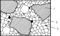
- FIG. 2 is a schematic cross-sectional view of a cBN sintered body according to one embodiment of the present invention.
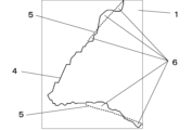
- 3A and 3B are schematic diagrams of a contour line and a contour approximation line.
- 1 is a schematic diagram showing coordinates (x i , yu i ) of a contour line and coordinates (P j , Q j ) of a contour approximation line;
- FIG. 3 is a partially enlarged view of FIG. 2 .
- the inventors conducted extensive research into the morphology of cBN particles in cBN sintered bodies. As a result, they discovered that when the external shape of the cBN particles has a specific irregular shape, the cBN particles are firmly bonded to the binder phase, improving the toughness of the cBN sintered body.
- the structure has a binder phase which is an aggregate of cBN particles (1) and binder phase particles (2), and Al compounds (3) are present in the binder phase.
- the cBN sintered body will be described below.
- the average particle size of the cBN particles is preferably 1000 nm or more and 6000 nm or less. If the average particle size is within this range, when the cBN sintered compact is used as a tool base of a cutting tool, chipping and defects originating from unevenness caused by falling off of cBN particles at the cutting edge are suppressed, and further, the propagation of cracks progressing from the interface between the cBN particles and the binder phase, or the propagation of cracks progressing due to the cracking of the cBN particles, can be suppressed.
- the average particle size of the cBN particles is more preferably 2000 nm or more and 5000 nm or less.
- the average particle size of the cBN particles is determined as follows.
- the surface or cross section of the cBN sintered compact is mirror-finished, and the observation area of the mirror-finished surface is observed with a scanning electron microscope (hereinafter referred to as SEM) (magnification, for example, 5000 times) to obtain a secondary electron image.
- SEM scanning electron microscope
- the cBN grains in the obtained image are extracted by binarization processing using image processing software, and the average grain size is calculated based on the maximum length (maximum Feret's diameter) of each cBN grain.
- any threshold value may be set so long as the perimeter of the cBN particles can be clearly detected in the image processing software.
- Each cBN particle is assumed to be an ideal sphere having this diameter, and the cumulative volume is calculated based on the volume of each particle. Based on this cumulative volume, a graph is drawn with the vertical axis representing volume percentage (%) and the horizontal axis representing diameter (nm), and the diameter when the volume percentage is 50% is taken as the average particle size of the cBN particles in that image. This is performed for any three or more observation regions, and the average value is taken as the average particle size (nm, this average particle size is called D50) of the cBN particles.
- the length (nm) per pixel is set using a scale value previously known from the SEM.
- the size of one observation area is preferably such that at least 30 cBN particles can be observed in the observation area.
- the binarization process, watershed image processing, and measurement of the maximum Feret's diameter may be performed using the same image processing software, or each may be performed using different image processing software. There are no particular restrictions on the image processing software used, and for example, Image J can be used.
- the content of cBN particles is not particularly limited, but is preferably 40 area % or more and 78 area % or less on the surface or cross section of the cBN sintered body. The reason is that if it is less than 40 area %, there are few cBN particles in the sintered body, and when it is used as a tool base for a cutting tool, the chipping resistance may decrease, while if it exceeds 78 area %, voids that become the starting points of cracks are generated in the sintered body, and the chipping resistance may decrease.
- the content of cBN particles is more preferably 50 area % or more and 75 area % or less.
- the cBN content is determined as follows. As in the case of determining the average particle size of cBN particles, the mirror-finished surface or cross section of the cBN sintered body is observed by SEM at a magnification of 5000 times, and the cBN particles in the observation area are extracted by binarization processing of image processing software.
- a process is performed to separate the cBN particles that are thought to be in contact with each other, for example, a watershed image processing is used to separate the cBN particles that are thought to be in contact with each other, and then the area occupied by the cBN particles is calculated, and the area ratio of the cBN particles in the observation area is calculated, and this is performed for any three or more observation areas, and the average value of the values obtained in each observation area is the content of the cBN particles.
- the size of the observation area is preferably the same as that when the average particle size of the cBN particles is obtained, and may be the same as the observation area for obtaining the average particle size of the cBN particles.
- the area ratio occupied by cBN can also be obtained by image processing software, and may be performed by the same image processing software as the binarization processing, watershed image processing, and measurement of the maximum Feret's diameter, or may be performed by another software.
- an XY coordinate that encompasses the entire cBN particle is set.
- the X axis is parallel to the maximum Feret diameter, and the coordinates of the outer periphery of the cBN particle are measured over the entire circumference of the outer periphery of the cBN particle at intervals d (d is an arbitrary value between 4.5 nm and 6.5 nm) in the X axis direction.
- the coordinates are measured for both above and below the maximum Feret diameter (the coordinates above the maximum Feret diameter are (x i , yu i ), and the coordinates below the maximum Feret diameter are (x i , yl i ).
- i 1 to n
- n [maximum Feret diameter/d]
- [ ] is the Gauss symbol
- d is the interval between adjacent x j + 1 and x j
- x j + 1 - x j d).
- Adjacent coordinates on both the upper and lower sides of the maximum Feret's diameter are connected by straight lines to define a contour line.
- the contour approximation line is obtained by averaging the coordinates of the periphery of the cBN particle obtained in (3-1) above as follows: The coordinates of the outer periphery of the cBN particle for which the average value is to be calculated and the coordinates of the contour line of 25 points each in the negative and positive directions of the X-axis with the coordinates as the origin, for a total of 51 points, are averaged to obtain the coordinates of the contour approximation line.
- FIG. 3 is a schematic diagram showing the aforementioned coordinates (x i , yui ) and coordinates (P j , Q j ), and "
- Figure 4 is an enlarged partial view of Figure 2, which shows an example of the contour line and the contour approximation line. Note that the binder phase particles are not shown in Figures 2 to 4.
- a cBN particle (1) forms an interface with the binder phase, which is an aggregate of binder phase particles (2), around it.
- the cBN particle and the binder phase are firmly bonded together by the anchor effect brought about by the irregularities of a specific shape around the cBN particle.
- the irregularities of this particular shape refer to the irregularities (6) formed by the contour line (4) and contour approximation line (5) of the cBN particle. It is preferable that the median (the definition of the median will be described later) of the areas of the irregularities (6) both above and below the Feret diameter (hereinafter, sometimes referred to as the irregularity area) is 500 nm2 or more and 2200 nm2 or less, and that the sum of the areas of the cBN particles satisfying this median accounts for 45% or more and 90% or less of the area of all the cBN particles.
- the median area of the unevenness of the contour line of the cBN grain is less than 500 nm2 , the number of protrusions and recesses that provide an anchor effect between the cBN grain and the binder phase will be insufficient, and toughness will not be improved.
- the recesses will act as notches that cause cracks in the cBN grains, and chipping resistance will decrease when used as a tool base for a cutting tool.
- the sum of the areas of the cBN particles having a median area of each of the projections and recesses of 500 nm2 or more and 2200 nm2 or less is 50% or more and 90% or less (even more preferably 60% or more and 80% or less) of the area of all the cBN particles in the sintered body.
- the median area of each of the concave and convex portions is 1000 nm2 or more and 2000 nm2 or less, and the sum of the areas of the cBN particles is 45% or more and 70% or less of the area of the entire cBN particles (even more preferably 50% or more and 65% or less).
- the sum of the areas of the cBN particles having a median area of each of the uneven portions of 500 nm2 or more and 2200 nm2 or less is 50% or more and 90% or less (more preferably 60% or more and 80% or less) of the area of all the cBN particles in the sintered body, and that the median area of each of the uneven portions is 1000 nm2 or more and 2000 nm2 or less and the sum of the areas of the cBN particles is 45% or more and 70% or less (more preferably 50% or more and 65% or less) of the area of the entire cBN particles.
- the surface or cross-sectional structure of the cBN sintered body is observed by SEM, and the cBN particle portion in the obtained observation image is extracted by binarization processing of any image processing software, and for cBN particles in which the total number (m) of unevenness formed by the contour line and the contour approximation line on the upper and lower sides of the Feret's diameter is 15 or more, the areas of the unevenness are arranged in ascending order (from smallest value to largest value), and the ratio of the total area of cBN particles whose median value ((m+1)/2 when m is an odd number, and m/2 when m is an even number) is 500 nm2 or more and 2200 nm2 or less (or 1000 nm2 or more and 2000 nm2 or less) to the total area of all cBN particles in the observation area is determined.
- the size of the observation area is set so that it contains
- the area of each uneven portion can be obtained by a known method such as the Monte Carlo method.
- cBN particles with a total number of uneven portions (m) of less than 15 are not used in calculating the median because the total number of uneven portions is insufficient, resulting in a large error in the median.
- the proportion of cBN particles with m less than 15 in the observation region is small, at 5% or less, and excluding them from the calculation of the median does not affect the results.
- binding phase is an aggregate of particulate binding phase particles, and the average particle size of the binding phase particles is preferably 100 nm or more and 230 nm or less. The reason is that if it is less than 100 nm, the thermal conductivity in the binding phase decreases, and the wear resistance decreases, while if it exceeds 230 nm, pores tend to remain in the sintered body during sintering, and the chipping resistance decreases.
- the average particle size of the binding phase is more preferably 130 nm or more and 200 nm or less.
- the average particle size of the binder phase particles is determined as follows. As in the case of determining the average grain size of cBN grains, the surface or cross section of the cBN sintered body is observed by SEM, and in the observation image at a magnification (for example, magnification: 50,000 times) at which the binder phase grains are clearly visible, the boundaries at which the brightness of the binder phase grains changes are regarded as grain boundaries of the binder phase grains, and the grain boundaries are extracted by binarization processing of the image processing software so that the grain boundaries can be clearly detected by the image processing software using the grain boundaries, and the maximum Feret diameter of each binder phase grain is regarded as the diameter of each binder phase grain. There are no particular restrictions on the image processing software used to determine the diameter of the binder phase grains.
- Each binder phase particle is assumed to be an ideal sphere having this diameter, and the cumulative volume is calculated based on the volume of each particle, and a graph is drawn based on this cumulative volume with the vertical axis representing volume percentage (%) and the horizontal axis representing diameter (nm), and the diameter at which the volume percentage is 50% is taken as the average particle size of the binder phase particles in that image. This is performed for any three or more observation areas, and the average value is taken as the average particle size (nm, this average particle size is called D50) of the binder phase particles.
- the length (nm) per pixel is set using a scale value previously known from the SEM. It is preferable that the observation region is a region in which at least 30 binder phase particles are observed.
- the main component of the binder phase can be prepared using raw material powders known as binder phase materials, such as TiN powder, TiC powder, TiCN powder, and TiAl3 powder.
- the binder phase contains Al compounds such as AlN, Al2O3 , and AlB2 , and the ratio of the area occupied by them to the entire cBN sintered body is preferably 1 area% or more and 12 area% or less.
- the reason is that if it is less than 1 area%, the reaction between the cBN particles and the binder phase is insufficient, resulting in a decrease in toughness, while if it exceeds 12 area%, the generation of Al compounds with low hardness is excessive, resulting in a decrease in fracture resistance when used as a tool base for a cutting tool.
- the Al compounds are present at the grain boundaries separated from the binder phase particles.
- the ratio of the area occupied by the Al compound in the cBN sintered compact is calculated from an Al element mapping image obtained by analyzing the surface or cross-sectional structure of the cBN sintered compact by Auger Electron Spectroscopy (hereinafter referred to as AES).
- AES Auger Electron Spectroscopy
- the overlapping portion of the Al element and elements other than Al is extracted as an Al compound by image processing using any image processing software, and the area occupied by the Al compound in the observed region is calculated by image analysis, and the area ratio is determined. This is performed for any three or more observed regions, and the average value of the calculated area ratios of each Al compound is determined as the area occupied by the Al compound in the cBN sintered compact.
- An example of the observation region used for image processing is a size of about 5.0 x 103 nm x 3.0 x 103 nm.
- raw material powders of components constituting the binder phase As raw materials that will be the main part of the binder phase, TiN powder, TiC powder, TiCN powder, and TiAl3 powder are prepared. These powders will be grain size adjusted pulverized powders and coarse grain raw material powders.
- the mixture is filled together with cBN powder of a predetermined average particle size into a ball mill container lined with cemented carbide, cemented carbide balls, acetone, and crushed and mixed in a ball mill, and dried to obtain a sintered raw material powder.
- the content (mass%) of the particle-size adjusted pulverized powder (mass of particle-size adjusted pulverized powder) / (mass of particle-size adjusted pulverized powder + mass of coarse-grained raw material powder) x 100 is preferably 50 to 100%.
- the sintered body raw material powder obtained above is molded at a predetermined pressure to produce a molded body, and this molded body is pre-sintered in a vacuum atmosphere, and then sintered at a pressure of 4 GPa and a temperature in the range of 1200 to 1600°C, for example, to produce a cBN sintered body of one embodiment of the present invention.
- a cBN sintered body having cBN particles and a binder phase The average particle size of the cBN particles is 1000 nm or more and 6000 nm or less, the sum of the areas of the cBN particles having a median area of each uneven portion formed by the contour line and the contour approximation line on the surface or cross section of the sintered body of 500 nm2 or more and 2200 nm2 or less is 45% or more and 90% or less of the area of all the cBN particles in the sintered body;
- the cBN sintered body is characterized in that the binder phase is an aggregate of binder phase particles having an average particle size of 100 nm or more and 230 nm or less, and further contains an Al compound, and the Al compound accounts for 1 area % or more and 12 area % or less of the entire cBN sintered body.
- (Appendix 2) The cBN sintered body according to claim 1, characterized in that the sum of the areas of the cBN grains having a median area of each of the projections and recesses of 500 nm2 or more and 2200 nm2 or less is 50% or more and 90% or less of the area of all the cBN grains in the sintered body.
- (Appendix 3) The cBN sintered body according to claim 1 or 2, characterized in that the sum of the areas of the cBN grains having a median area of each of the projections and recesses of 500 nm2 or more and 2200 nm2 or less is 60% or more and 80% or less of the area of all the cBN grains in the sintered body.
- a TiN powder and a TiAl 3 powder were prepared, pulverized in a ball mill, and then classified using a centrifugal separation method to prepare pulverized powders with an average particle size in the range of 50 to 100 nm as shown in Table 1.
- Coarse grain raw powder with average particle size range of TiN and TiAl3 of 520-580nm shown in Table 1 was prepared separately, and this coarse grain raw powder was blended and mixed with the grain size adjusted pulverized powder to obtain the raw powder for the binder phase.
- the content (mass%) of grain size adjusted pulverized powder shown in Table 1 is (mass of grain size adjusted pulverized powder)/(mass of grain size adjusted pulverized powder+mass of coarse grain raw powder) ⁇ 100. Note that there are also examples that do not contain coarse grain raw powder.
- the mass ratio of TiN to TiAl3 powder was the same for the coarse grain raw powder and the grain size adjusted pulverized powder.
- cBN powder was further blended as the raw material for the hard phase to the raw powder for the binder phase, acetone was added, wet mixing was performed for 24 hours, and drying was performed to obtain the raw powder for the sintered body.
- the resulting sintered body raw material powder was then press molded at a molding pressure of 1 MPa to dimensions of 50 mm diameter x 1.5 mm thickness, and this molded body was then pre-sintered at 1000°C in a vacuum atmosphere with a pressure of 1 Pa or less. It was then loaded into an ultra-high pressure sintering apparatus and sintered at a pressure of 4 GPa, a temperature of 1400°C, and the sintering time shown in Table 1 to produce example sintered bodies 1 to 11 shown in Table 2.
- the primary purpose of the pre-sintering performed on the molded body here was to remove the solvent that had been present during wet mixing.
- the manufacturing process for the sintered body of the above example was carried out in a non-oxidizing atmosphere, since it is preferable to prevent oxidation of the raw material powder in the process up to ultra-high pressure sintering.
- raw powders of TiN powder and TiAl 3 powder were prepared, and grain size-adjusted pulverized powder with the average grain size shown in Table 1 was prepared in the same manner as in the embodiment.
- the coarse grain raw powder with the average grain size shown in Table 1 was mixed in the same manner as in the embodiment so as to have the ratio shown in Table 1 (100-mass% of grain size-adjusted pulverized powder) to prepare a raw powder for forming the binder phase of the comparative example.
- cBN powder was separately prepared, and these powders were mixed in the same manner as in the embodiment, pre-sintered in the same manner as in the embodiment, and sintered under the conditions shown in Table 1 to prepare comparative example sintered bodies 1 to 10 shown in Table 2.
- the mass ratio of TiN to TiAl 3 powder was the same for the coarse grain raw powder and the grain size-adjusted pulverized powder.
- the comparative example sintered body was prepared in a non-oxidizing atmosphere in the same manner as in the embodiment sintered body.
- the cBN particles were extracted using Image J (version 1.44p) as image processing software, and the secondary electron images obtained by the SEM were automatically binarized by the minimum method, and a series of operations were performed, including measurement of particle size, calculation of area ratio, and definition of the contour line.
- the interval d when determining the contour line and the contour approximation line was set to 5.5 nm.
- Extraction of binder phase particles and measurement of particle size were also performed using Image J (version 1.44p) in the same manner. That is, the grain boundaries of binder phase particles were detected by Find Edge processing of secondary electron images obtained by SEM, and automatic binarization processing was performed by the Huang method to measure the particle size. The area of the uneven portion was determined by the Monte Carlo method.
- the number of cBN particles whose unevenness area was measured indicates the number of cBN particles whose outer circumference was clearly visible and whose unevenness area was measured in the observation area of the secondary electron image at a magnification of 20,000 times obtained by observing the cBN sintered body by SEM.
- the ratio of the number of cBN particles whose total number of unevenness, m, was less than 15 was less than 5% of the total cBN particles, and therefore was excluded from the evaluation.
- area ratio 1 (%) indicates the ratio of the sum of the areas of cBN particles whose median area of the unevenness of the cBN particles whose unevenness area was measured is in the range of 500 nm2 or more and 2200 nm2 or less to the sum of the areas of all cBN particles
- area ratio 2 (%) indicates the ratio of the sum of the areas of cBN particles whose median area is in the range of 1000 nm2 or more and 2000 nm2 or less to the sum of the areas of all cBN particles.
- the size of the observation area of each example sintered body and each comparative example sintered body was as described in Table 3.
- the content of Al compounds was calculated from the Al element mapping image obtained by analysis using AES spectroscopy.
- the portion where the Al element overlaps with elements other than Al was taken as the Al compound, and extracted by image processing using Image J (version 1.44p), and the area occupied by the Al compound in the observation region was calculated by image analysis to obtain the area ratio. This was performed for any three or more observation regions, and the average value of the calculated area ratios of each Al compound was obtained as the content of Al compounds in the cBN sintered body.
- the size of the observation region was (5.0 x 10³ nm) x (3.8 x 10³ nm).
- the sintered bodies 1-11 of the examples and 1-10 of the comparative examples were cut to the specified dimensions using a wire electric discharge machine. Then, brazing (composition of brazing material: Cu: 26% by mass, Ti: 5% by mass, Ag and unavoidable impurities: remainder) was applied to the brazing portion (corner portion) of the insert body made of WC-based cemented carbide (composition: Co: 5% by mass, TaC: 5% by mass, WC and unavoidable impurities: remainder) with an insert shape conforming to ISO standard CNGA120408, and the upper and lower surfaces and outer circumference were polished and honed to produce cutting tools 1-11 of the examples and cutting tools 1-10 of the comparative examples, each with an insert shape conforming to ISO standard CNGA120408.
Landscapes
- Chemical & Material Sciences (AREA)
- Engineering & Computer Science (AREA)
- Mechanical Engineering (AREA)
- Materials Engineering (AREA)
- Organic Chemistry (AREA)
- Ceramic Engineering (AREA)
- Metallurgy (AREA)
- Manufacturing & Machinery (AREA)
- Structural Engineering (AREA)
- Crystallography & Structural Chemistry (AREA)
- Cutting Tools, Boring Holders, And Turrets (AREA)
Priority Applications (1)
| Application Number | Priority Date | Filing Date | Title |
|---|---|---|---|
| JP2024564366A JP7773703B2 (ja) | 2022-12-16 | 2023-12-11 | cBN焼結体および切削工具 |
Applications Claiming Priority (2)
| Application Number | Priority Date | Filing Date | Title |
|---|---|---|---|
| JP2022-201336 | 2022-12-16 | ||
| JP2022201336 | 2022-12-16 |
Publications (1)
| Publication Number | Publication Date |
|---|---|
| WO2024128178A1 true WO2024128178A1 (ja) | 2024-06-20 |
Family
ID=91484983
Family Applications (1)
| Application Number | Title | Priority Date | Filing Date |
|---|---|---|---|
| PCT/JP2023/044174 Ceased WO2024128178A1 (ja) | 2022-12-16 | 2023-12-11 | cBN焼結体および切削工具 |
Country Status (2)
| Country | Link |
|---|---|
| JP (1) | JP7773703B2 (https=) |
| WO (1) | WO2024128178A1 (https=) |
Citations (7)
| Publication number | Priority date | Publication date | Assignee | Title |
|---|---|---|---|---|
| JP2008517868A (ja) * | 2004-10-29 | 2008-05-29 | エレメント シックス (プロダクション)(プロプライエタリィ) リミテッド | 立方晶系窒化硼素成形体 |
| JP2015044259A (ja) * | 2013-08-27 | 2015-03-12 | 三菱マテリアル株式会社 | 耐欠損性にすぐれた立方晶窒化硼素焼結体切削工具 |
| JP2018145020A (ja) * | 2017-03-01 | 2018-09-20 | 三菱マテリアル株式会社 | cBN焼結体および切削工具 |
| WO2021182462A1 (ja) * | 2020-03-13 | 2021-09-16 | 三菱マテリアル株式会社 | 硬質複合材料 |
| WO2021182463A1 (ja) * | 2020-03-13 | 2021-09-16 | 三菱マテリアル株式会社 | 硬質複合材料 |
| JP2021151943A (ja) * | 2020-03-25 | 2021-09-30 | 三菱マテリアル株式会社 | cBN焼結体および切削工具 |
| WO2022210771A1 (ja) * | 2021-03-31 | 2022-10-06 | 三菱マテリアル株式会社 | 掘削チップおよび掘削工具 |
-
2023
- 2023-12-11 JP JP2024564366A patent/JP7773703B2/ja active Active
- 2023-12-11 WO PCT/JP2023/044174 patent/WO2024128178A1/ja not_active Ceased
Patent Citations (7)
| Publication number | Priority date | Publication date | Assignee | Title |
|---|---|---|---|---|
| JP2008517868A (ja) * | 2004-10-29 | 2008-05-29 | エレメント シックス (プロダクション)(プロプライエタリィ) リミテッド | 立方晶系窒化硼素成形体 |
| JP2015044259A (ja) * | 2013-08-27 | 2015-03-12 | 三菱マテリアル株式会社 | 耐欠損性にすぐれた立方晶窒化硼素焼結体切削工具 |
| JP2018145020A (ja) * | 2017-03-01 | 2018-09-20 | 三菱マテリアル株式会社 | cBN焼結体および切削工具 |
| WO2021182462A1 (ja) * | 2020-03-13 | 2021-09-16 | 三菱マテリアル株式会社 | 硬質複合材料 |
| WO2021182463A1 (ja) * | 2020-03-13 | 2021-09-16 | 三菱マテリアル株式会社 | 硬質複合材料 |
| JP2021151943A (ja) * | 2020-03-25 | 2021-09-30 | 三菱マテリアル株式会社 | cBN焼結体および切削工具 |
| WO2022210771A1 (ja) * | 2021-03-31 | 2022-10-06 | 三菱マテリアル株式会社 | 掘削チップおよび掘削工具 |
Also Published As
| Publication number | Publication date |
|---|---|
| JP7773703B2 (ja) | 2025-11-20 |
| JPWO2024128178A1 (https=) | 2024-06-20 |
Similar Documents
| Publication | Publication Date | Title |
|---|---|---|
| JP5305056B1 (ja) | 立方晶窒化ほう素基焼結体製切削工具 | |
| JP6032409B2 (ja) | 立方晶窒化ほう素基超高圧焼結体を工具基体とする切削工具、表面被覆切削工具 | |
| JP2021151943A (ja) | cBN焼結体および切削工具 | |
| JP6198142B2 (ja) | 立方晶窒化ホウ素基超高圧焼結材料製切削工具 | |
| CN113286770A (zh) | 立方晶氮化硼烧结体及其制造方法和工具 | |
| JP6968341B2 (ja) | 微細構造組織を有する立方晶窒化ほう素基焼結体および切削工具 | |
| JP7773703B2 (ja) | cBN焼結体および切削工具 | |
| JP5804448B2 (ja) | 立方晶窒化ほう素基超高圧焼結体およびこれを工具基体とする切削工具、表面被覆切削工具 | |
| JP7773704B2 (ja) | cBN焼結体および切削工具 | |
| JP7598089B2 (ja) | cBN焼結体および切削工具 | |
| JP7377463B2 (ja) | cBN焼結体および切削工具 | |
| JP5312095B2 (ja) | 切削工具 | |
| CN111801304B (zh) | cBN烧结体及切削工具 | |
| JP6933017B2 (ja) | 立方晶窒化ほう素基焼結体および切削工具 | |
| JP7096977B2 (ja) | cBN焼結体および切削工具 | |
| JP2024124819A (ja) | cBN焼結体 | |
| JP7161670B2 (ja) | 立方晶窒化ほう素基焼結体および切削工具 | |
| JP6986232B2 (ja) | 立方晶窒化ほう素基焼結体及びこれからなる切削工具 | |
| JP2024138951A (ja) | cBN焼結体 | |
| JP2022142894A (ja) | cBN焼結体 | |
| WO2022196637A1 (ja) | 表面被覆切削工具 | |
| JP2024111448A (ja) | 立方晶窒化硼素焼結体 | |
| JP2020001990A (ja) | cBN焼結体および切削工具 |
Legal Events
| Date | Code | Title | Description |
|---|---|---|---|
| 121 | Ep: the epo has been informed by wipo that ep was designated in this application |
Ref document number: 23903464 Country of ref document: EP Kind code of ref document: A1 |
|
| WWE | Wipo information: entry into national phase |
Ref document number: 2024564366 Country of ref document: JP |
|
| NENP | Non-entry into the national phase |
Ref country code: DE |
|
| 122 | Ep: pct application non-entry in european phase |
Ref document number: 23903464 Country of ref document: EP Kind code of ref document: A1 |