WO2024128049A1 - マイクロレンズアレイ、及び投影装置 - Google Patents
マイクロレンズアレイ、及び投影装置 Download PDFInfo
- Publication number
- WO2024128049A1 WO2024128049A1 PCT/JP2023/043247 JP2023043247W WO2024128049A1 WO 2024128049 A1 WO2024128049 A1 WO 2024128049A1 JP 2023043247 W JP2023043247 W JP 2023043247W WO 2024128049 A1 WO2024128049 A1 WO 2024128049A1
- Authority
- WO
- WIPO (PCT)
- Prior art keywords
- microlens array
- lens
- aspheric
- inflection point
- dimensional direction
- Prior art date
- Legal status (The legal status is an assumption and is not a legal conclusion. Google has not performed a legal analysis and makes no representation as to the accuracy of the status listed.)
- Ceased
Links
Images




Classifications
-
- G—PHYSICS
- G02—OPTICS
- G02B—OPTICAL ELEMENTS, SYSTEMS OR APPARATUS
- G02B3/00—Simple or compound lenses
- G02B3/0006—Arrays
- G02B3/0037—Arrays characterized by the distribution or form of lenses
- G02B3/0043—Inhomogeneous or irregular arrays, e.g. varying shape, size, height
-
- G—PHYSICS
- G02—OPTICS
- G02B—OPTICAL ELEMENTS, SYSTEMS OR APPARATUS
- G02B3/00—Simple or compound lenses
-
- G—PHYSICS
- G02—OPTICS
- G02B—OPTICAL ELEMENTS, SYSTEMS OR APPARATUS
- G02B3/00—Simple or compound lenses
- G02B3/0006—Arrays
- G02B3/0037—Arrays characterized by the distribution or form of lenses
- G02B3/0056—Arrays characterized by the distribution or form of lenses arranged along two different directions in a plane, e.g. honeycomb arrangement of lenses
-
- G—PHYSICS
- G02—OPTICS
- G02B—OPTICAL ELEMENTS, SYSTEMS OR APPARATUS
- G02B3/00—Simple or compound lenses
- G02B3/02—Simple or compound lenses with non-spherical faces
- G02B3/04—Simple or compound lenses with non-spherical faces with continuous faces that are rotationally symmetrical but deviate from a true sphere, e.g. so called "aspheric" lenses
-
- G—PHYSICS
- G03—PHOTOGRAPHY; CINEMATOGRAPHY; ANALOGOUS TECHNIQUES USING WAVES OTHER THAN OPTICAL WAVES; ELECTROGRAPHY; HOLOGRAPHY
- G03B—APPARATUS OR ARRANGEMENTS FOR TAKING PHOTOGRAPHS OR FOR PROJECTING OR VIEWING THEM; APPARATUS OR ARRANGEMENTS EMPLOYING ANALOGOUS TECHNIQUES USING WAVES OTHER THAN OPTICAL WAVES; ACCESSORIES THEREFOR
- G03B21/00—Projectors or projection-type viewers; Accessories therefor
-
- G—PHYSICS
- G03—PHOTOGRAPHY; CINEMATOGRAPHY; ANALOGOUS TECHNIQUES USING WAVES OTHER THAN OPTICAL WAVES; ELECTROGRAPHY; HOLOGRAPHY
- G03B—APPARATUS OR ARRANGEMENTS FOR TAKING PHOTOGRAPHS OR FOR PROJECTING OR VIEWING THEM; APPARATUS OR ARRANGEMENTS EMPLOYING ANALOGOUS TECHNIQUES USING WAVES OTHER THAN OPTICAL WAVES; ACCESSORIES THEREFOR
- G03B21/00—Projectors or projection-type viewers; Accessories therefor
- G03B21/14—Details
- G03B21/20—Lamp housings
- G03B21/208—Homogenising, shaping of the illumination light
Definitions
- the present invention relates to a microlens array and a projection device.
- FIG. 1 is a schematic diagram of a conventional lens array, where (A) is a top view and (B) is a vertical cross-sectional view.
- a conventional diffuser having an array of concave lenses the depth of the concave lenses is varied as d1, d2, ..., and the central coordinate C position of the concave lenses is varied in the in-plane direction.
- d1, d2, ... the depth of the concave lenses
- the central coordinate C position of the concave lenses is varied in the in-plane direction.
- FIG. 1A equally spaced positions in the XY plane are shown as dotted circles as a reference.
- the central coordinate C of the concave lenses is shifted from the center of the equally spaced positions in both the X and Y directions, and the pitch is varied as P1, P2, ... in the XY plane.
- the depth d and pitch P of the concave lenses are varied to suppress diffracted light from being generated only in a specific direction.
- the inventors discovered that if there is variation in the lens pitch in a microlens array, it becomes difficult to provide good cutoff characteristics in the diffuse light profile. However, a regular lens arrangement with little variation in pitch raises concerns about the occurrence of diffracted bright spots.
- the present invention was made in consideration of the above situation, and aims to provide a microlens array that has good cutoff characteristics and suppresses the occurrence of diffraction spots.
- n the total number of inflection points that the cross-sectional shape of one row of aspheric lenses arranged in a desired one-dimensional direction has in an area excluding 12.5% at both ends of each aspheric lens.
- An inflection point is defined as a point where the sign of d"(x), which is the second derivative of d(x), changes when the cross-sectional shape of the aspheric lens is expressed as a function d(x) of the depth d of the aspheric lens and the distance x in the desired one-dimensional direction.
- X the sum of distances x [ ⁇ m] in a desired one-dimensional direction, excluding 12.5% at both ends of each aspheric lens in one row of aspheric lenses arranged in a desired one-dimensional direction
- a microlens array is realized that has good cutoff characteristics and suppresses the occurrence of diffraction spots.
- FIG. 1 is a schematic diagram of a conventional lens array.
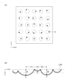
- 1A and 1B are a schematic cross-sectional view and a top view image of a microlens array according to an embodiment.
- FIG. 2 is a schematic top view of a microlens array according to an embodiment. This is a cross-sectional view of X-X' in Figure 3.
- FIG. 1 is a diagram illustrating a lens shape having an inflection point and a lens shape having no inflection point.
- FIG. 13 is a diagram illustrating a method for calculating an inflection point density N.
- FIG. 1 illustrates a diffusion profile with a "flat" top region.
- FIG. 1 illustrates a diffusion profile where the top region is not "flat.”
- 11 is a simulation diagram of a diffusion profile when the in-plane pitch variation of an aspheric lens is changed.
- FIG. 13 illustrates the change in cutoff band as a function of pitch variation.
- FIG. 13 is a diagram illustrating how to determine a cutoff band.
- FIG. 13 is a diagram for explaining how to determine a slope as a cutoff characteristic.
- 1 is a schematic diagram of a projection device to which a microlens array according to an embodiment is applied.
- FIG. 1 shows the diffusion profile in the X direction of Example 1.
- FIG. 13 shows the diffusion profile in the X direction of Example 2.
- FIG. 13 shows the diffusion profile in the X direction of Example 3.
- FIG. 13 shows the diffusion profile in the X direction of Example 4.
- FIG. 13 shows the diffusion profile in the X direction of Example 6.
- FIG. 13 shows the diffusion profile in the X direction of Example 5.
- the inflection point density N defined by the above formula (1) in at least one row of the aspherical lens array is set to a certain range, and pitch variation of the aspherical lenses is suppressed within the plane of the first surface.
- the inflection point density N is set to 0.50 to 0.80 [/ ⁇ m], more preferably 0.60 to 0.75 [/ ⁇ m].
- the inflection point density N is set in the above range in at least one row of aspheric lenses.
- the pitch variation relative to the average of all pitches in the area excluding both ends of the aspheric lenses arranged in a desired one-dimensional direction within the plane of the first surface is suppressed to less than 7.5%, more preferably to 5.0% or less.
- FIG. 2 shows an example of a microlens array 10 according to one embodiment.
- (A) in FIG. 2 is a schematic cross-sectional view of the microlens array 10, and
- (B) is an image viewed from above.
- a plurality of aspherical lenses 13 are formed on a first surface 101 of a substrate 11 that is transparent to the wavelength used.
- the plurality of aspherical lenses 13 form a row in the X direction.
- the row is aligned in the Y direction.
- the plurality of aspherical lenses 13 are provided at the lattice points of a square lattice, and are arranged in a square lattice.
- FIG. 2A shows a schematic cross section of one row of aspherical lenses 13 in a desired one-dimensional direction on the first surface 101, in this example, the X direction.
- At least one row of the arrangement of the aspherical lenses 13 in the desired one-dimensional direction has an inflection point density N of 0.60 to 0.80 [/ ⁇ m].
- an inflection point refers to a point where the lens shape of the aspherical lens 13 changes from an upwardly convex shape to a downwardly convex shape (or from a downwardly convex shape to an upwardly convex shape), and is defined as a point where the sign of d''(x), which is the second derivative of d(x), changes when the cross-sectional shape of the aspherical lens 13 is expressed as a function d(x) of the depth d of the aspherical lens 13 and the distance x in a desired one-dimensional direction, changes.
- the occurrence of diffracted bright spots can be suppressed by setting the inflection point density N, which is an index of the number of inflection points present in at least one row of the arrangement of the aspherical lenses 13 in the desired one-dimensional direction in the microlens array 10, within the above range.
- the pitch P between the centers 14 of the aspheric lenses 13 is almost constant. "Almost constant” means that the pitch variation is suppressed to be smaller than a predetermined variation.
- the pitch variation indicates the absolute value of the maximum possible difference of the randomly distributed relative pitch ratio in the entire pitch in the region of the lens in the one-dimensional direction when the average pitch of the region excluding both ends of the entire pitch in the desired one-dimensional direction is set to 1, and this is expressed as ⁇ p .
- the pitch variation ⁇ p of the aspheric lenses 13 in the region excluding both ends is suppressed to less than 0.075, that is, the variation with respect to the average pitch is suppressed to less than 7.5%.
- the white dots in the center of each aspherical lens 13 indicate the lens center.
- the microlens array 10 includes a square lattice arrangement of aspherical lenses 13, and has a nearly constant pitch in each of the X direction (horizontal direction of the paper) and Y direction (vertical direction of the paper).
- the absolute value of the pitch correlates with the diffusion angle in that direction.
- the aspect ratio of the pitch in the X direction and the Y direction is set to be greater than 1, but when forming a square projected image, the pitch of the aspherical lenses 13 may be designed to be the same value in the X direction and the Y direction.
- the pitch variation of the aspherical lenses 13 in one-dimensional directions such as the X direction and the Y direction is suppressed to less than 7.5%, more preferably 5.0% or less, resulting in a nearly regular lens arrangement in the in-plane direction.
- Fig. 3 is a schematic top view of a sample of a microlens array 10 according to an embodiment
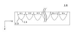
- Fig. 4 is a schematic view of the XX' cross section of Fig. 3.
- a plurality of aspherical lenses 13 are regularly arranged in the XY plane.
- the aspherical lenses 13 arranged in the microlens array 10 have a local change in lens shape (see the area surrounded by the dotted line), and this local change is caused by an inflection point of the aspherical lenses 13.
- the inflection point means a point at which the lens shape changes from an upward convex shape to a downward convex shape (or from a downward convex shape to an upward convex shape).
- n the total number of inflection points that the cross-sectional shape of one row of aspheric lenses arranged in a desired one-dimensional direction has in an area excluding 12.5% at both ends of each aspheric lens.
- An inflection point is defined as a point where the sign of d"(x), which is the second derivative of d(x), changes when the cross-sectional shape of the aspheric lens is expressed as a function d(x) of the depth d of the aspheric lens and the distance x in the desired one-dimensional direction.
- X the sum of distances x [ ⁇ m] in a desired one-dimensional direction, excluding 12.5% on both ends of each aspheric lens, in one row of aspheric lenses arranged in a desired one-dimensional direction.
- the inflection point density N is the sum n of the number of inflection points in the cross-sectional shape of one row of aspherical lenses arranged in a desired one-dimensional direction in the microlens array 10, excluding 12.5% at both ends of each aspherical lens, divided by X, which is the sum of the distances x in the desired one-dimensional direction excluding 12.5% at both ends of each aspherical lens, i.e., the sum of the distances x corresponding to the area in each aspherical lens where the number of inflection points is counted.
- the inflection point is defined as the point at which the sign of d''(x), which is the second derivative of d(x), changes when the cross-sectional shape of the aspheric lens is expressed as a function d(x) of the depth d of the aspheric lens and the distance x in a desired one-dimensional direction.
- the function d(x) can be obtained, for example, by the following steps (I) to (III).
- a laser microscope is used to measure the three-dimensional shape of each aspherical lens of the microlens array. Measurement conditions may be, for example, horizontal resolution of 0.556 ⁇ m and depth resolution of 0.100 ⁇ m.
- the depth d of the aspherical lens in a desired cross section of the microlens array is measured.
- III The measurement points of the depth d are connected to obtain the function d(x).
- a VK-X3000 manufactured by Keyence Corporation
- FIG. 5(a) shows an example of the cross-sectional shape of an aspheric lens that has an inflection point.
- the cross-sectional shape of the aspheric lens is expressed as a function d(x) of the depth d of the aspheric lens and the distance x in a desired one-dimensional direction.
- the aspherical lens in Figure 5(a) has two inflection points. As shown in Figure 5(b), at the inflection points, the sign of d''(x), which is the second derivative of d(x), changes. Therefore, by counting the points where the sign of d''(x) changes, it is possible to find the number of inflection points present in the aspherical lens (for example, eight in Figure 5(b)).
- Figure 5(c) is an example of the cross-sectional shape of an aspherical lens that does not have an inflection point. As shown in Figure 5(d), in the case of an aspherical lens that does not have an inflection point, there is no point where the sign of d''(x) changes.
- the number of inflection points that each aspheric lens 13 has is counted in the area (x1, x2, x3, ..., xk-1, xk) excluding 12.5% at both ends of each aspheric lens 13, and the sum of these is taken as N in formula (1).
- it can be calculated by dividing the calculated N by the sum X ( x1 + x2 + x3 + ... + xk-1 + xk) of the distances in the desired one-dimensional direction (corresponding to the X direction in Figure 6) in the area excluding 12.5% at both ends of each aspheric lens.
- the cross-sectional shape of a row of aspheric lenses in a desired one-dimensional direction is the shape of a cross section that passes through the centers 14 of the aspheric lenses 13 at both ends of the array and is perpendicular to the first surface 101 of the substrate 11.
- the microlens array 10 by setting the inflection point density N to 0.50 to 0.80 [/ ⁇ m] in at least one row of the aspheric lens arrangement in the desired one-dimensional direction, the occurrence of diffraction bright spots can be suppressed.
- the inflection point density N is preferably 0.50 to 0.75 [/ ⁇ m], and more preferably 0.60 to 0.75 [/ ⁇ m].
- the inflection point density N is 0.80 [/ ⁇ m] or less.
- the inflection point density N within the above-mentioned preferred range, the occurrence of diffraction bright spots is suppressed, and a diffusion profile with a flat intensity distribution at the top can be obtained.
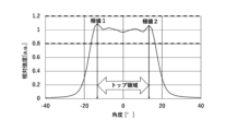
- the top of the diffusion profile when the top of the diffusion profile is said to be "flat,” it means that when the diffusion profile in a desired one-dimensional direction is normalized to have an average intensity of 1 in the range of diffusion angles of the diffused light from -10 degrees to +10 degrees, the minimum value of the relative intensity in the top region of the diffusion profile is 0.800 or more and the maximum value is 1.200 or less.
- the top region refers to the region between two diffusion angles at which the relative intensity has an extreme value, where the range of diffusion angles is the largest, and the diffusion angle at which the relative intensity has an extreme value refers to the diffusion angle value at which the relative intensity of the diffusion profile switches from increasing to decreasing, or from decreasing to increasing.
- Figure 7 is an example of a diffusion profile with a "flat" top intensity distribution.
- the minimum value of the relative intensity is 0.800 or more and the maximum value is 1.200 or less.
- such a diffusion profile is said to have a "flat" top.
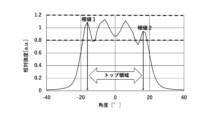
- Figure 8 is an example of a diffusion profile where the top intensity distribution is not "flat.”
- the minimum value of the relative intensity is less than 0.800 in the top region between extreme value 1 and extreme value 2, where the range of diffusion angles is at its maximum, out of the two diffusion angle points where the intensity distribution takes extreme values.
- the cutoff characteristics of the microlens array 10 refer to the abruptness of the change in whether light is diffused or blocked in a specified direction.
- the "FOV" of the microlens array 10 refers to the angle range where the relative intensity is 0.5 or more when the diffusion profile is normalized with the average intensity in the diffusion angle range of -10° to +10° set to 1.
- Figure 9 shows an enlarged view of a portion of the diffusion profile on the positive side. It can be seen that the larger the in-plane pitch variation, the more gradual the rise or fall of the diffusion profile becomes, and the worse the cutoff characteristics become.
- Figure 10 shows a plot of the cutoff band as a function of pitch variation from the simulation results of Figure 9.
- the cutoff band is the angular width required for the intensity of the diffusion profile to change to a given level. A more precise definition of the cutoff band is described with reference to Figure 11.
- FIG. 11 is a diagram explaining how to determine the cutoff band.
- the "cutoff band" is the angle width required for the relative intensity to change between 0.200 and 0.800.
- the relative intensity of the diffusion profile is the intensity when the average intensity in the diffusion angle range of -10° to +10° is normalized to 1.
- the angle width when the relative intensity changes from 0.200 to 0.800 or from 0.800 to 0.200 is obtained on both the negative and positive sides of the diffusion profile, and the larger of the two angle widths is determined as the cutoff band.
- FIG. 12 is a diagram explaining how to determine the slope.
- the slope can be calculated by the following steps (I) to (III).
- (I) The average intensity in the diffusion angle range of -10° to +10° is normalized as 1.
- (II) The points on the negative and positive sides of the diffusion profile where the relative intensity is closest to 0.200 and 0.800 are connected, and the slope of the line is determined.
- (III) The smaller of the absolute values of the two slopes determined is taken as the slope. From the viewpoint of obtaining good cutoff characteristics, the slope is preferably 1.0/° or more, more preferably 1.1/° or more, and even more preferably 1.2/° or more.
- the pitch variation of the aspheric lens 13 is smaller than 0.075 (or 7.5%), and more preferably 0.050 (or 5.0%) or less.
- the microlens array 10 can obtain a diffusion profile with good cutoff characteristics and suppressed occurrence of diffraction bright spots.
- the depth variation of the aspherical lenses 13 in the microlens array 10 is preferably 1.50 ⁇ m or more, more preferably 1.70 ⁇ m or more, from the viewpoint of suppressing the occurrence of diffraction spots.
- the depth variation is preferably 6.00 ⁇ m or less, more preferably 4.00 ⁇ m or less.
- the depth variation is 1 ⁇ when the depth of the aspherical lenses 13 of the microlens array 10 follows a normal distribution, and is the variation (standard deviation) from the median or mean value.
- the variation in the radius of curvature R of the aspheric lenses 13 in the microlens array 10 is preferably 3.50 ⁇ m or more, and more preferably 3.70 ⁇ m or more, from the viewpoint of suppressing the occurrence of diffracted bright spots. Since there is a concern that the cutoff performance of the diffusion profile may decrease, the variation in the radius of curvature R is preferably 8.00 ⁇ m or less, and more preferably 6.00 ⁇ m or less.
- the variation in the radius of curvature R is 1 ⁇ when the radius of curvature R of the aspheric lenses 13 in the microlens array 10 follows a normal distribution, and is the variation (standard deviation) from the median or mean value.
- the depth and the radius of curvature of the aspheric lenses 13 in the microlens array 10 may be varied.
- the inflection point density N is within the above-mentioned preferred range, it is possible to suppress diffracted bright spots even if the variation in the depth and the radius of curvature of the aspheric lenses is not within the preferred range.
- the diffusion angle of the microlens array 10 is not particularly limited and can be designed appropriately depending on the purpose, but is preferably 30° or more, and more preferably 40° or more.
- the wavelength used i.e., the light incident on the microlens array 10, can be any wavelength that is transparent to the substrate 11, but it is preferable for the light to be in at least a portion of the wavelength range between 400 and 1000 nm.
- FIG. 13 is a schematic diagram of a projection device 20 to which the microlens array 10 of one embodiment is applied.
- the projection device 20 includes a light source 21, a lens 22, and a microlens array 10.
- the light source 21 is, for example, a light-emitting diode (LED).
- the light emitted from the light source 21 is collimated into parallel light by the lens 22 and enters the microlens array 10.
- the microlens array 10 is provided on the exit side of the light source 21 and diffuses and projects the light emitted from the light source 21.
- the microlens array 10 diffuses the incident parallel light in the X and Y directions with a specified FOV and projects it onto the screen 25. If a laser light source is used instead of an LED as the light source, the collimating lens 22 may be omitted. To obtain a color projection image, a microlens array 10 may be arranged for each of a red light source, a green light source, and a blue light source, and the light emitted from each microlens array 10 may be combined using a prism or the like and projected onto the screen 25.
- the microlens array 10 of one embodiment can be applied not only to projection devices, but also to lighting devices, imaging systems, etc.
- Wavelength selectivity can be achieved by tuning the pitch itself while suppressing pitch variation of the aspheric lenses within the plane. In this case, light of a specific wavelength can be diffused, making it suitable for application to color projection devices.
- the method for manufacturing the aspheric lenses 13 in the microlens array 10 is not particularly limited, but for example, the aspheric lenses 13 are formed by performing wet etching on a pretreated base material.
- the pretreatment is preferably a method in which a pulsed laser beam is irradiated to a certain position on the base material 11 to modify a partial area inside the base material, and a density distribution is provided in the thickness direction at the position irradiated with the pulsed laser beam.
- the shape of the aspheric lens 13 is determined by a combination of factors, such as the wavelength, frequency, power, pulse width, and focal position of the laser light used during pretreatment. The following describes the preferred conditions for the manufacturing method according to one embodiment.
- the wavelength of the laser light is not particularly limited, but examples include 1026 nm, 1064 nm, and 532 nm, with 1064 nm being preferred.
- the frequency of the laser light is preferably 10 to 50 kHz.
- the power of the laser light is preferably 0.60 W or more from the viewpoint of modifying the substrate sufficiently to form a lens.
- it is preferably 1.00 W or less, and more preferably 0.90 W or less.
- the pulse width of the laser light is preferably 20 ps or less, and more preferably 15 ps or less, since it is necessary to rapidly cool the laser light after irradiation.
- the lower limit of the pulse width is not particularly limited, but may be, for example, 1 ps or more.
- the focal position of the laser light is preferably -0.250 to +0.100 mm, and more preferably -0.150 to +0.00 mm.
- the focal position of the laser light is considered to be 0 mm at the first surface 101 of the substrate 11, and the traveling direction of the laser light (the direction from the first surface 101 of the substrate 11 into the substrate 11) is considered to be the + direction.
- Table 1 shows the laser light irradiation conditions, inflection point density N, minimum and maximum relative intensity in the top region of the diffusion profile, pitch variation, diffusion profile slope, depth variation, and curvature radius variation for each sample in Examples 1 to 6.
- the depth variation and curvature radius variation are 1 ⁇ when the depth and curvature radius follow a normal distribution, and are the variation (standard deviation) from the average value.
- Figures 14 to 19 show the diffusion profiles in the X direction for Examples 1 to 6.
- the diffusion profiles are shown in terms of relative intensity normalized by taking the average intensity of the diffused light in the diffusion angle range of -10 degrees to +10 degrees as 1.
- the wavelength of the incident light when measuring the diffusion profile was 940 nm.
- Examples 1 to 4 correspond to working examples, and Examples 5 and 6 correspond to comparative examples.
- Examples 1 to 6 are microlens array samples in which the reference pitch in the X direction is 40 ⁇ m and the reference pitch in the Y direction is 40 ⁇ m, with a total of 100 aspheric lenses arranged in 10 rows in the X direction and 10 rows in the Y direction. As shown in Table 1, the pitch variation is different for each sample.
- the aspheric lenses were fabricated by irradiating the substrate with pulsed laser light, carrying out pretreatment to modify part of the substrate's interior, and then carrying out wet etching with hydrofluoric acid.
- the etching time was 35 minutes.
- the conditions for the laser light irradiation during pretreatment were a wavelength of 1064 nm, a frequency of 20 kHz, and a pulse width of 10 to 15 ps, which were the same for Examples 1 to 6.
- the power and focal length of the laser light were different for Examples 1 to 6, and were as shown in Table 1.
- the laser light was irradiated onto the processing point while room temperature air was applied to it.
- a desired row was selected from the 10 rows of aspherical lenses arranged in the X direction for each of the produced samples, and the inflection point density N was calculated for the 10 aspherical lenses on the lens array based on the above formula (1).
- the cross-sectional shape of the aspherical lens when calculating the inflection point density N was the shape of a cross section that passes through the centers of the aspherical lenses at both ends of the array and is perpendicular to the first surface of the substrate.
- Examples 5 and 6 which have lens arrangements in which the inflection point density N is outside the above-mentioned preferred range, the minimum value of the relative intensity in the top region of the diffusion profile is less than 0.800, and it is observed that diffraction bright spots, which are localized concentrations of light, occur. From the above, it can be seen that by setting the inflection point density N within the above preferred range, the occurrence of diffraction bright spots can be suppressed and a flat diffusion profile can be realized.
- Table 1 shows that in all of Examples 1 to 6, the pitch variation is within the preferred range described above, so the slope of the diffusion profile is 0.10/° or more, and the diffusion profile has good cutoff characteristics.
- the slope of the diffusion profile was calculated using the following steps (I) to (III).
- the data used for the calculation is shown in Table 2.
- (I) The average intensity in the diffusion angle range of -10° to +10° is normalized as 1.
- (II) On the negative and positive sides of the diffusion profile, the points with the closest relative intensity values of 0.200 and 0.800 are connected, and the slope of the line is determined.
- (III) The smaller of the absolute values of the two slopes determined is taken as the slope.
- microlens arrays of Examples 1 to 4 which correspond to the working examples, have good cutoff characteristics and suppress the occurrence of diffracted bright spots by setting the inflection point density N and pitch variation within the above-mentioned preferred ranges.
Landscapes
- Physics & Mathematics (AREA)
- General Physics & Mathematics (AREA)
- Optics & Photonics (AREA)
- Lenses (AREA)
Priority Applications (2)
| Application Number | Priority Date | Filing Date | Title |
|---|---|---|---|
| JP2024564294A JPWO2024128049A1 (https=) | 2022-12-15 | 2023-12-04 | |
| US19/223,408 US20250291092A1 (en) | 2022-12-15 | 2025-05-30 | Microlens array and projection device |
Applications Claiming Priority (2)
| Application Number | Priority Date | Filing Date | Title |
|---|---|---|---|
| JP2022200185 | 2022-12-15 | ||
| JP2022-200185 | 2022-12-15 |
Related Child Applications (1)
| Application Number | Title | Priority Date | Filing Date |
|---|---|---|---|
| US19/223,408 Continuation US20250291092A1 (en) | 2022-12-15 | 2025-05-30 | Microlens array and projection device |
Publications (1)
| Publication Number | Publication Date |
|---|---|
| WO2024128049A1 true WO2024128049A1 (ja) | 2024-06-20 |
Family
ID=91484827
Family Applications (1)
| Application Number | Title | Priority Date | Filing Date |
|---|---|---|---|
| PCT/JP2023/043247 Ceased WO2024128049A1 (ja) | 2022-12-15 | 2023-12-04 | マイクロレンズアレイ、及び投影装置 |
Country Status (3)
| Country | Link |
|---|---|
| US (1) | US20250291092A1 (https=) |
| JP (1) | JPWO2024128049A1 (https=) |
| WO (1) | WO2024128049A1 (https=) |
Citations (5)
| Publication number | Priority date | Publication date | Assignee | Title |
|---|---|---|---|---|
| JP2010204518A (ja) * | 2009-03-05 | 2010-09-16 | Toppan Printing Co Ltd | 複数の変曲点を有する単位レンズを配した光学シート |
| JP2013084375A (ja) * | 2011-10-06 | 2013-05-09 | Toppan Printing Co Ltd | 照明装置、ディスプレイ装置、液晶ディスプレイ装置 |
| JP2014038314A (ja) * | 2012-07-19 | 2014-02-27 | Asahi Glass Co Ltd | 光学素子、投影装置および計測装置並びに製造方法 |
| JP2021056503A (ja) * | 2019-09-26 | 2021-04-08 | ナルックス株式会社 | 拡散素子 |
| WO2021230324A1 (ja) * | 2020-05-13 | 2021-11-18 | Scivax株式会社 | 光学系装置および光学素子製造方法 |
-
2023
- 2023-12-04 JP JP2024564294A patent/JPWO2024128049A1/ja active Pending
- 2023-12-04 WO PCT/JP2023/043247 patent/WO2024128049A1/ja not_active Ceased
-
2025
- 2025-05-30 US US19/223,408 patent/US20250291092A1/en active Pending
Patent Citations (5)
| Publication number | Priority date | Publication date | Assignee | Title |
|---|---|---|---|---|
| JP2010204518A (ja) * | 2009-03-05 | 2010-09-16 | Toppan Printing Co Ltd | 複数の変曲点を有する単位レンズを配した光学シート |
| JP2013084375A (ja) * | 2011-10-06 | 2013-05-09 | Toppan Printing Co Ltd | 照明装置、ディスプレイ装置、液晶ディスプレイ装置 |
| JP2014038314A (ja) * | 2012-07-19 | 2014-02-27 | Asahi Glass Co Ltd | 光学素子、投影装置および計測装置並びに製造方法 |
| JP2021056503A (ja) * | 2019-09-26 | 2021-04-08 | ナルックス株式会社 | 拡散素子 |
| WO2021230324A1 (ja) * | 2020-05-13 | 2021-11-18 | Scivax株式会社 | 光学系装置および光学素子製造方法 |
Also Published As
| Publication number | Publication date |
|---|---|
| JPWO2024128049A1 (https=) | 2024-06-20 |
| US20250291092A1 (en) | 2025-09-18 |
Similar Documents
| Publication | Publication Date | Title |
|---|---|---|
| US11378812B2 (en) | Diffuser plate and method for designing diffuser plate | |
| CN110161602B (zh) | 漫射板、漫射板的设计方法、显示装置、投影装置和照明装置 | |
| JP5343752B2 (ja) | 導光板、導光板の製造方法、面光源装置および液晶表示装置 | |
| US9939561B2 (en) | Projector having diffuser | |
| TWI713502B (zh) | 擴散板 | |
| US10877188B2 (en) | Composite diffuser plate | |
| JP6424418B2 (ja) | 光学素子、投影装置および計測装置並びに製造方法 | |
| JP6884518B2 (ja) | 拡散板、拡散板の設計方法、拡散板の製造方法、表示装置、投影装置及び照明装置 | |
| JP3747207B2 (ja) | ディスプレイ用ライトユニット | |
| JP6430048B1 (ja) | 拡散板及び光学機器 | |
| JP2003043266A (ja) | 面発光装置の導光板 | |
| JP5584858B2 (ja) | 光学装置 | |
| JP6678524B2 (ja) | 照明装置 | |
| US20200407271A1 (en) | Diffusion element, lighting module, and method for processing aspheric lens | |
| US9274433B2 (en) | Fly eye lens and proximity exposure machine optical system | |
| WO2024128049A1 (ja) | マイクロレンズアレイ、及び投影装置 | |
| JP5210709B2 (ja) | 光源ユニット | |
| KR20030078305A (ko) | 반사형 도광판 및 이를 이용한 백라이트 유닛 | |
| JP7823327B2 (ja) | マイクロレンズアレイ、投影装置用拡散板、及び投影装置 | |
| US20130135897A1 (en) | Back light unit | |
| JP2023039292A (ja) | 光学素子 | |
| CN120315076B (zh) | 光学系统以及激光雷达 | |
| JP6928139B2 (ja) | 照明装置 | |
| KR20250078930A (ko) | 백라이트 디스플레이용 백라이트 유닛 | |
| WO2024034458A1 (ja) | 光学部材および照明装置 |
Legal Events
| Date | Code | Title | Description |
|---|---|---|---|
| 121 | Ep: the epo has been informed by wipo that ep was designated in this application |
Ref document number: 23903338 Country of ref document: EP Kind code of ref document: A1 |
|
| WWE | Wipo information: entry into national phase |
Ref document number: 2024564294 Country of ref document: JP |
|
| NENP | Non-entry into the national phase |
Ref country code: DE |
|
| 122 | Ep: pct application non-entry in european phase |
Ref document number: 23903338 Country of ref document: EP Kind code of ref document: A1 |