WO2024127927A1 - 内燃機関 - Google Patents
内燃機関 Download PDFInfo
- Publication number
- WO2024127927A1 WO2024127927A1 PCT/JP2023/041772 JP2023041772W WO2024127927A1 WO 2024127927 A1 WO2024127927 A1 WO 2024127927A1 JP 2023041772 W JP2023041772 W JP 2023041772W WO 2024127927 A1 WO2024127927 A1 WO 2024127927A1
- Authority
- WO
- WIPO (PCT)
- Prior art keywords
- exhaust
- valve
- intake
- combustion chamber
- exhaust valve
- Prior art date
- Legal status (The legal status is an assumption and is not a legal conclusion. Google has not performed a legal analysis and makes no representation as to the accuracy of the status listed.)
- Ceased
Links
Images




Classifications
-
- F—MECHANICAL ENGINEERING; LIGHTING; HEATING; WEAPONS; BLASTING
- F01—MACHINES OR ENGINES IN GENERAL; ENGINE PLANTS IN GENERAL; STEAM ENGINES
- F01L—CYCLICALLY OPERATING VALVES FOR MACHINES OR ENGINES
- F01L1/00—Valve-gear or valve arrangements, e.g. lift-valve gear
- F01L1/02—Valve drive
- F01L1/04—Valve drive by means of cams, camshafts, cam discs, eccentrics or the like
- F01L1/08—Shape of cams
-
- F—MECHANICAL ENGINEERING; LIGHTING; HEATING; WEAPONS; BLASTING
- F01—MACHINES OR ENGINES IN GENERAL; ENGINE PLANTS IN GENERAL; STEAM ENGINES
- F01L—CYCLICALLY OPERATING VALVES FOR MACHINES OR ENGINES
- F01L1/00—Valve-gear or valve arrangements, e.g. lift-valve gear
- F01L1/12—Transmitting gear between valve drive and valve
-
- F—MECHANICAL ENGINEERING; LIGHTING; HEATING; WEAPONS; BLASTING
- F02—COMBUSTION ENGINES; HOT-GAS OR COMBUSTION-PRODUCT ENGINE PLANTS
- F02B—INTERNAL-COMBUSTION PISTON ENGINES; COMBUSTION ENGINES IN GENERAL
- F02B31/00—Modifying induction systems for imparting a rotation to the charge in the cylinder
- F02B31/04—Modifying induction systems for imparting a rotation to the charge in the cylinder by means within the induction channel, e.g. deflectors
- F02B31/06—Movable means, e.g. butterfly valves
-
- F—MECHANICAL ENGINEERING; LIGHTING; HEATING; WEAPONS; BLASTING
- F02—COMBUSTION ENGINES; HOT-GAS OR COMBUSTION-PRODUCT ENGINE PLANTS
- F02D—CONTROLLING COMBUSTION ENGINES
- F02D13/00—Controlling the engine output power by varying inlet or exhaust valve operating characteristics, e.g. timing
- F02D13/02—Controlling the engine output power by varying inlet or exhaust valve operating characteristics, e.g. timing during engine operation
-
- F—MECHANICAL ENGINEERING; LIGHTING; HEATING; WEAPONS; BLASTING
- F02—COMBUSTION ENGINES; HOT-GAS OR COMBUSTION-PRODUCT ENGINE PLANTS
- F02F—CYLINDERS, PISTONS OR CASINGS, FOR COMBUSTION ENGINES; ARRANGEMENTS OF SEALINGS IN COMBUSTION ENGINES
- F02F1/00—Cylinders; Cylinder heads
- F02F1/24—Cylinder heads
-
- F—MECHANICAL ENGINEERING; LIGHTING; HEATING; WEAPONS; BLASTING
- F02—COMBUSTION ENGINES; HOT-GAS OR COMBUSTION-PRODUCT ENGINE PLANTS
- F02F—CYLINDERS, PISTONS OR CASINGS, FOR COMBUSTION ENGINES; ARRANGEMENTS OF SEALINGS IN COMBUSTION ENGINES
- F02F1/00—Cylinders; Cylinder heads
- F02F1/24—Cylinder heads
- F02F1/42—Shape or arrangement of intake or exhaust channels in cylinder heads
-
- Y—GENERAL TAGGING OF NEW TECHNOLOGICAL DEVELOPMENTS; GENERAL TAGGING OF CROSS-SECTIONAL TECHNOLOGIES SPANNING OVER SEVERAL SECTIONS OF THE IPC; TECHNICAL SUBJECTS COVERED BY FORMER USPC CROSS-REFERENCE ART COLLECTIONS [XRACs] AND DIGESTS
- Y02—TECHNOLOGIES OR APPLICATIONS FOR MITIGATION OR ADAPTATION AGAINST CLIMATE CHANGE
- Y02T—CLIMATE CHANGE MITIGATION TECHNOLOGIES RELATED TO TRANSPORTATION
- Y02T10/00—Road transport of goods or passengers
- Y02T10/10—Internal combustion engine [ICE] based vehicles
- Y02T10/12—Improving ICE efficiencies
Definitions
- This disclosure relates to an internal combustion engine.
- the internal combustion engine of Patent Document 1 utilizes this type of exhaust-side swirl flow to improve the deterioration of combustibility caused by the drop in intake charging efficiency in the low load range. Specifically, the internal combustion engine of Patent Document 1 uses a swirl control valve to generate a swirl flow on the intake side as well, mixing the swirl flow on the exhaust side with the swirl flow on the intake side to promote the flow of the mixture inside the cylinder.
- the objective of this disclosure is to provide an internal combustion engine with good combustion efficiency.
- the internal combustion engine comprises a combustion chamber, an exhaust passage connected to the combustion chamber, a first exhaust valve that opens and closes between the exhaust passage and the combustion chamber, and a second exhaust valve that is disposed adjacent to the first exhaust valve and opens and closes the exhaust passage, the opening period of the second exhaust valve being shorter than the opening period of the first exhaust valve, and the first exhaust valve and the second exhaust valve are closed simultaneously.
- the peak of the exhaust pressure rise in the exhaust passage where the first exhaust valve opens and closes is offset from the peak of the exhaust pressure rise in the exhaust passage where the second exhaust valve opens and closes. This reduces exhaust interference in the exhaust passage and also suppresses the maximum value of the exhaust pressure. As a result, exhaust backflow is suppressed and combustion efficiency is improved.
- This disclosure makes it possible to provide an internal combustion engine with good combustion efficiency.
- FIG. 1 is a system diagram of a vehicle equipped with an internal combustion engine according to one embodiment of the present disclosure.
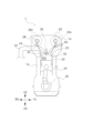
- 1 is a cross-sectional view of an internal combustion engine according to one embodiment of the present disclosure.
- 1 is a bottom view of a combustion chamber of an internal combustion engine according to one embodiment of the present disclosure; 1 illustrates a camshaft of an internal combustion engine according to one embodiment of the present disclosure.
- FIG. 2 is a diagram showing lift curves of intake and exhaust valves of an internal combustion engine according to one embodiment of the present disclosure.
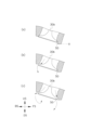
- FIG. 4 is a cross-sectional view taken along line aa of FIG.
- FIG. 4 is a cross-sectional view taken along line AA of FIG.
- FIG. 4 is a cross-sectional view taken along line BB of FIG. 3.
- FIG. 4 is a cross-sectional view taken along line bb of FIG. 3.
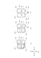
- 2 is a diagram showing the flow of a mixture in a combustion chamber during the intake, compression, and expansion strokes of an internal combustion engine according to an embodiment of the present disclosure;
- FIG. FIG. 2 illustrates the flow of exhaust gas in a combustion chamber during an exhaust stroke of an internal combustion engine according to one embodiment of the present disclosure.
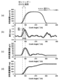
- 5 is a graph showing an example of a state in which exhaust interference is reduced;
- FS indicates the front side of the electric vehicle C
- BS indicates the rear side of the electric vehicle C
- RS indicates the right side of the electric vehicle C
- LS indicates the left side of the electric vehicle C
- US indicates the upper side of the electric vehicle C
- DS indicates the lower side of the electric vehicle C.
- the internal combustion engine 1 is mounted on an electric vehicle C that drives wheels C1 using the internal combustion engine 1 and a motor (FrM) 2 as power sources.
- the electric vehicle C has the motor 2, a generator (GEN) 4, a drive battery (BT) 6 including a secondary battery such as a lithium ion battery, and a transaxle 8.
- the transaxle 8 has multiple gears and a clutch 8a.
- the internal combustion engine 1 is connected to the generator 4 and the axle 10 via the transaxle 8. When the clutch 8a is in the disengaged state, the transaxle 8 cuts off the power transmission between the internal combustion engine 1 and the axle 10, and when the clutch 8a is in the engaged state, the power of the internal combustion engine 1 is transmitted to the axle 10.
- the motor 2 is connected to the axle 10 via the transaxle 8.
- the electric vehicle C may have a vehicle control device 12, an engine control device 14 that controls the internal combustion engine 1, an accelerator pedal 16 operated by a user of the electric vehicle C, an inverter 18 that controls the motor 2 and the generator 4, and a charging button (not shown).
- the electric vehicle C of this embodiment has various modes, such as EV mode, series mode, parallel mode, and charging mode.
- EV mode the electric vehicle C drives the motor 2 with power from the drive battery 6.
- series mode the electric vehicle C drives the generator 4 with the internal combustion engine 1 and drives the motor 2 with the power generated by the generator 4.
- parallel mode the electric vehicle C connects the clutch 8a and drives the axle 10 with the power of the internal combustion engine 1.
- charging mode the electric vehicle C drives the generator 4 with the internal combustion engine 1 and stores the power generated by the generator 4 in the drive battery 6.
- the vehicle control device 12 switches between each mode depending on the depression state of the accelerator pedal 16 and the operation state of the charge button, controls the motor 2 and the generator 4 via the inverter 18, and has the engine control device 14 control the internal combustion engine 1.
- Such an electric vehicle C uses the motor 2 when the electric vehicle C runs in the low load range.
- the electric vehicle C uses the internal combustion engine 1 in series mode, parallel mode, and charging mode. In these series mode, parallel mode, and charging mode, the internal combustion engine 1 is mainly operated in the high load operating range. For this reason, the internal combustion engine 1 used in such an electric vehicle C is required to have good combustion efficiency in the high load operating range.
- the internal combustion engine 1 includes a cylinder head 1a, a cylinder block 1b, a plurality of cylinders 20, an intake port (an example of an intake passage) 22, an exhaust port (an example of an exhaust passage) 24, an intake camshaft 26, an exhaust camshaft 28, a plurality of intake valves 30, a plurality of exhaust valves 32, a piston 34, a crankshaft 36, a spark plug 38, and a fuel injection valve 40.
- the internal combustion engine 1 of this embodiment is a horizontally mounted type in which the cylinders 20 of the internal combustion engine 1 are arranged side by side along the direction of the axle 10 of the wheel C1 of the electric vehicle C (the left-right direction of the electric vehicle C).
- each cylinder 20 accommodates a piston 34 that is slidably connected to the crankshaft 36 via a connecting rod.
- a combustion chamber 20a is formed between the piston 34 and the lower surface of the cylinder head 1a.
- the combustion chamber 20a is a pent roof type combustion chamber 20a with ridges formed in the left-right direction of the internal combustion engine 1.
- the intake port 22 is formed in the cylinder head 1a and connected to the slope on the intake side (front side in FIG. 2) of the combustion chamber 20a.
- the exhaust port 24 is formed in the cylinder head 1a and connected to the slope on the exhaust side (rear side in FIG. 2) of the combustion chamber 20a.
- An ignition plug 38 is disposed at the center O of the combustion chamber 20a (see FIG. 3).
- the internal combustion engine 1 in this embodiment is a gasoline engine.
- the intake port 22 is provided in each of the four cylinders 20 and is a passage that supplies intake air to the combustion chamber 20a.
- the intake port 22 is branched to the left and right by the intake port wall 22a, with a first intake port 22b located on the right side and a second intake port 22c located on the left side.
- the fuel injection valve 40 is located forward of the branch of the intake port 22. Fuel is supplied to the fuel injection valve 40 from a fuel tank 54 (see Figure 1), and the fuel injected from the fuel injection valve 40 and the air passing through the intake port 22 are mixed and supplied to the combustion chamber 20a.
- an exhaust port 24 is provided in each of the four cylinders 20, and is a passage for discharging exhaust gas generated after the mixture is burned in the combustion chamber 20a.
- the exhaust port 24 is branched to the left and right by the exhaust port wall 24a, with a first exhaust port 24b located on the right side and a second exhaust port 24c located on the left side.
- the exhaust port 24 of each cylinder 20 is connected to an exhaust manifold 25.
- the exhaust manifold 25 collects and discharges the exhaust flowing through the exhaust ports 24 located in each cylinder 20.
- the intake valve 30 opens and closes between the intake port 22 and the combustion chamber 20a.
- the intake valve 30 has a first intake valve 30a located on the right side, and a second intake valve 30b located adjacent to the first intake valve 30a and located on the left side.
- the first intake valve 30a opens and closes between the first intake port 22b and the combustion chamber 20a.
- the second intake valve 30b opens and closes between the second intake port 22c and the combustion chamber 20a.
- the exhaust valve 32 opens and closes between the exhaust port 24 and the combustion chamber 20a.
- the exhaust valve 32 has a first exhaust valve 32a located on the left side, and a second exhaust valve 32b located adjacent to the first exhaust valve 32a and located on the right side.
- the first exhaust valve 32a opens and closes between the second exhaust port 24c and the combustion chamber 20a.
- the second exhaust valve 32b opens and closes between the first exhaust port 24b and the combustion chamber 20a.
- the intake valve 30 is a direct-hit valve that is driven by the cam of the intake camshaft 26 pushing out the intake valve 30.
- the intake camshaft 26 in this embodiment has a first intake cam 26a that drives the first intake valve 30a and a second intake cam 26b that drives the second intake valve 30b.
- the intake camshaft 26 has one set of the first intake cam 26a and the second intake cam 26b arranged in one cylinder 20. For example, if there are four cylinders 20, four first intake cams 26a and four second intake cams 26b are arranged.
- the first intake valve 30a oscillates along the cam profile of the first intake cam 26a, resulting in a lift curve as shown in FIG. 5.
- the second intake valve 30b oscillates along the cam profile of the second intake cam 26b, resulting in a lift curve as shown in FIG. 5.
- the first intake cam 26a and the second intake cam 26b are split cams with different phases and cam profiles. Specifically, the second intake cam 26b is retarded more than the first intake cam 26a. This causes the second intake valve 30b to open later than the first intake valve 30a. Furthermore, the cam profile of the first intake cam 26a and the cam profile of the second intake cam 26b are formed so that the timing at which the first intake valve 30a changes from the maximum lift position P1 to the closed valve position P0 and the timing at which the second intake valve 30b changes from the maximum lift position P1 to the closed valve position P0 are simultaneous. In other words, the first intake valve 30a and the second intake valve 30b close simultaneously.
- the opening period of the second intake valve 30b is shorter than the opening period of the first intake valve 30a.
- the cam profile of the second intake cam 26b may be linearly symmetrical or asymmetrical, with the upward profile of the cam from the closed position P0 to the maximum lift position P1 and the downward profile of the cam from the maximum lift position P1 to the closed position P0.
- An asymmetrical cam profile of the second intake cam 26b may be, for example, one in which the upward period is shorter than the downward period, or one in which the downward period is shorter than the upward period.
- the exhaust valve 32 is a direct-hit valve that is driven by the cam of the exhaust camshaft 28 pushing out the exhaust valve 32.
- the exhaust camshaft 28 in this embodiment has a first exhaust cam 28a that drives the first exhaust valve 32a and a second exhaust cam 28b that drives the second exhaust valve 32b.
- the exhaust camshaft 28 has one set of the first exhaust cam 28a and the second exhaust cam 28b arranged in one cylinder 20. For example, if there are four cylinders 20, four first exhaust cams 28a and four second exhaust cams 28b are arranged.
- the first exhaust valve 32a oscillates along the cam profile of the first exhaust cam 28a, resulting in a lift curve as shown in FIG. 5.
- the second exhaust valve 32b oscillates along the cam profile of the second exhaust cam 28b, resulting in a lift curve as shown in FIG. 5.
- the first exhaust cam 28a and the second exhaust cam 28b are split cams with different phases and cam profiles.
- the second exhaust cam 28b is retarded more than the first exhaust cam 28a. This causes the second exhaust valve 32b to open later than the first exhaust valve 32a.
- the cam profile of the first exhaust cam 28a is formed so that the first exhaust valve 32a is at the maximum lift position P2, while the cam profile of the second exhaust cam 28b is formed so that the second exhaust valve 32b is at the maximum lift position P3 that is lower than the maximum lift position P2.
- the maximum lift position P3 of the second exhaust valve 32b is lower than the maximum lift position P2 of the first exhaust valve 32a.
- the cam profile of the first exhaust cam 28a and the cam profile of the second exhaust cam 28b are formed so that the timing when the first exhaust valve 32a changes from the maximum lift position P2 to the closed valve position P0 and the timing when the second exhaust valve 32b changes from the maximum lift position P3 to the closed valve position P0 are the same. That is, the first exhaust valve 32a and the second exhaust valve 32b are closed at the same time. Also, the opening period of the second exhaust valve 32b is shorter than the opening period of the first exhaust valve 32a.
- the cam profile of the second exhaust cam 28b may be linearly symmetrical or asymmetrical in the ascending profile of the cam from the closed valve position P0 to the maximum lift position P3 and the descending profile of the cam from the maximum lift position P3 to the closed valve position P0.
- An example of an asymmetrical cam profile of the second exhaust cam 28b is one in which the descending period is shorter than the ascending period.
- the cam profile of the second exhaust cam 28b may be formed so that the lift curve rises gradually from the valve closing position P0.
- the maximum lift position P1 of the first intake valve 30a and the second intake valve 30b is higher than the maximum lift position P2 of the first exhaust valve 32a and the maximum lift position P3 of the second exhaust valve 32b.
- the lift amounts of the first intake valve 30a and the second intake valve 30b are lower than the lift amounts of the first exhaust valve 32a and the second exhaust valve 32b.
- the internal combustion engine 1 further includes an intake variable valve timing device 26c capable of changing the phase of the intake camshaft 26, and an exhaust variable valve timing device 28c capable of changing the phase of the exhaust camshaft 28.
- the intake variable valve timing device 26c and the exhaust variable valve timing device 28c can adjust the valve overlap amount between the first intake valve 30a and the second intake valve 30b and the first exhaust valve 32a and the second exhaust valve 32b by changing the phase of each camshaft.
- the combustion chamber 20a is formed asymmetrically with respect to the center line O1 of the combustion chamber 20a. That is, the shape of the combustion chamber 20a is asymmetric between the side where the first exhaust valve 32a is arranged and the side where the second exhaust valve 32b is arranged, with the center line O1 of the combustion chamber 20a in between. More specifically, the combustion chamber 20a is formed such that the right wall 42 between the first intake valve 30a and the first exhaust valve 32a bulges out in a direction away from the center O of the combustion chamber 20a more than the left wall 44 between the second intake valve 30b and the second exhaust valve 32b. In this embodiment, the right wall 42 is formed bulging in an arc shape along the cylindrical shape of the cylinder 20.
- an intake shroud 45 is formed across the first intake valve 30a and the second intake valve 30b, and the intake shroud 45 has an intake shroud protrusion (part of the intake shroud 45) 46 between the first intake valve 30a and the second intake valve 30b that protrudes toward the center O of the combustion chamber 20a.
- a first shroud wall 48 is formed on the intake shroud 45 around the first intake valve 30a side, and is formed so that the height of the first shroud wall 48 on the A-A cross section is higher (see reference line Y in Figure 7(a)) when the height of the first shroud wall 48 on the a-a cross section is taken as the reference (see reference line X in Figure 6(a)).
- FIG. 3 FIG. 8 and FIG.
- the intake shroud 45 around the second intake valve 30b side is formed with a second shroud wall 50, and the height of the second shroud wall 50 at the b-b section is the same as the height of the first shroud wall 48 at the a-a section (see reference line X in FIG. 9(a)), and the height of the second shroud wall 50 at the B-B section is the same as the height of the second shroud wall 50 at the A-A section (see reference line in FIG. 8(a)).
- the gap between the second intake valve 30b and the second shroud wall 50 is formed in a shape that is larger than the gap between the first intake valve 30a and the first shroud wall 48 (see gap D in FIG. 8(a)).
- the exhaust shroud 51 is formed across the first exhaust valve 32a and the second exhaust valve 32b, and the exhaust shroud 51 has an exhaust shroud protrusion 52 formed between the first exhaust valve 32a and the second exhaust valve 32b.
- the first intake valve 30a opens first during the intake stroke.
- the intake shroud 45 causes the first shroud wall 48 to obstruct the flow from the FS side of the first intake valve 30a, and as shown by the arrows in Figures 6(b) and 7(b), the mixture flows into the combustion chamber 20a biased toward the BS side of the first intake valve 30a, forming a tumble flow.
- the mixture also flows into the combustion chamber 20a from the FS side of the valve, as shown by the arrows in Figures 6(c) and 7(c).
- the height of the first shroud wall 48 around the intake shroud protrusion 46 is set higher than the first shroud wall 48 other than the intake shroud protrusion 46, and the flow of the incoming mixture is obstructed, causing a deviation in the mixture flow to the left and right, and as shown by the arrows in FIG. 10(a), the flow along the first shroud wall 48 and the right wall 42 is strengthened, and in addition to the tumble flow, a swirl flow is also formed in the combustion chamber 20a along the circumferential direction of the cylinder 20.
- the second intake valve 30b opens as shown in FIG. 5.
- the intake shroud 45 prevents the flow from the FS side of the second intake valve 30b by the second shroud wall 50, and as shown by the arrows in FIG. 8(b) and FIG. 9(b), the mixture flows into the combustion chamber 20a biased toward the BS side of the second intake valve 30b, forming a tumble flow.
- the mixture also flows into the combustion chamber 20a from the FS side of the valve as shown by the arrows in FIG. 8(c) and FIG. 9(c).
- the height of the second shroud wall 50 on the second intake valve 30b side is the same as that on the first intake valve side due to the intake shroud protrusion 46, but by providing a gap D between the second intake valve 30b and the second shroud wall 50, the mixture without a swirl flow flows into the combustion chamber 20a.
- the gap D between the second intake valve 30b and the second shroud wall 50 as the height of the shroud wall decreases i.e., the shape is such that it moves away from the second intake valve 30b as it moves toward the center O, see also FIG. 3
- a uniform flow rate can be made to flow into the combustion chamber 20a from the entire circumferential surface of the second intake valve 30b.
- the amount of mixture that flows into the combustion chamber 20a can be made larger, and the swirl flow formed by opening the first intake valve 30a is maintained without being hindered even when the second intake valve 30b is opened. Furthermore, since the first intake valve 30a and the second intake valve 30b are closed at the same time, it is also possible to suppress the swirl flow from flowing back from the second intake valve 30b.
- the swirl flow of the mixture thus formed in the combustion chamber 20a becomes a flow with its center biased toward the first intake valve 30a during the compression stroke after the first intake valve 30a and the second intake valve 30b are closed.
- the mixture with such a swirl flow is ignited by the spark plug 38 and burns. Therefore, the flame that is generated after the mixture is ignited propagates vigorously throughout the combustion chamber 20a over the unburned mixture, which has become highly turbulent due to the collapse of the tumble flow before ignition, and the maintained swirl flow with its center bias helps to uniformize the uneven flame propagation, improving the degree of volume constancy and preventing knocking caused by the end gas of the unburned mixture.
- the first exhaust valve 32a opens first, followed by the second exhaust valve 32b.
- the first exhaust valve 32a is located diagonally opposite the first intake valve 30a across the center O. Therefore, as shown by the arrow in FIG. 11(a), the swirl flow biased toward the first intake valve 30a is maintained for a longer period of time compared to when the first exhaust valve 32a opens before the second exhaust valve 32b. This shortens the flame propagation during the expansion stroke, improves the degree of constant volume, and improves combustion efficiency.
- the second exhaust valve 32b opens later than the first exhaust valve 32a, so there is less exhaust interference than when the first exhaust valve 32a and the second exhaust valve 32b are opened simultaneously.
- the first exhaust valve 32a opens first, and exhaust flows into the second exhaust port 24c.
- the second exhaust valve 32b opens later than the first exhaust valve 32a, and exhaust flows into the first exhaust port 24b.
- the exhaust pressure in the second exhaust port 24c increases first, and the exhaust pressure generated in the first exhaust port 24b increases later. This reduces exhaust interference at the junction of the first exhaust port 24b and the second exhaust port 24c, and the maximum value of the exhaust pressure also decreases.
- the opening period of the second exhaust valve 32b is shorter than the opening period of the first exhaust valve 32a, and the lift amount of the second exhaust valve 32b is also smaller than the lift amount of the first exhaust valve 32a. This further reduces exhaust interference. Therefore, the amount of exhaust gas (internal EGR) that flows back into the combustion chamber 20a due to exhaust interference is reduced. As a result, not only can knocking be suppressed, but scavenging of the combustion chamber 20a is also made easier.
- 12(a) to 12(d) are graphs showing an example of reduced exhaust interference, where the solid line representing the exhaust split EC alignment is a graph in the case where the first exhaust valve 32a and the second exhaust valve 32b according to this embodiment are used, and the dashed line representing the normal cam is a graph of a conventional cam profile.
- the lift amount of the first exhaust valve 32a and the second exhaust valve 32b is smaller than the lift amount of the first intake valve 30a and the second intake valve 30b.
- the internal combustion engine 1 can further reduce exhaust interference, making it easier to suppress exhaust backflow, especially in the high load region.
- first exhaust valve 32a and the second exhaust valve 32b are closed simultaneously during the exhaust stroke. That is, as shown in FIG. 12(b), by making the exhaust pressure rise in the first exhaust port 24b slower than that in the second exhaust port 24c, it is possible to make the timing N2 at which the exhaust pressure rise reaches its maximum value slower than the timing N1 at which the exhaust pressure rise reaches its maximum value in the normal cam. Therefore, the internal combustion engine 1 can shift the timing at which the exhaust pressure rises and reaches its maximum value during the valve overlap period (VOL period in FIG. 12) in another cylinder 20. This allows the internal combustion engine 1 to suppress backflow from the exhaust and further suppress exhaust interference with the other cylinder 20. As a result, as shown in FIG. 12(d), it is possible to suppress exhaust backflow due to exhaust interference in the exhaust manifold 25 in the cylinder 20 as well, shorten the exhaust valve opening period, and avoid deterioration of exhaust efficiency due to a reduced lift amount.
- the valve overlap between the first intake valve 30a and the second exhaust valve 32b is reduced compared to when the second exhaust valve 32b is closed later than the first exhaust valve 32a.
- immediately combusted gas internal EGR gas
- the mixture that flows into the combustion chamber 20a when the first intake valve 30a opens can be prevented from blowing through the second exhaust valve 32b. As a result, it becomes easier to generate a swirl flow, and the charging efficiency is also improved.
- this disclosure makes it possible to provide an internal combustion engine with good combustion efficiency.
- an electric vehicle C having various modes such as EV mode, series mode, parallel mode, and charging mode has been described as an example, but the present disclosure is not limited to this.
- the electric vehicle C is not limited to these modes, and may have any mode that uses the internal combustion engine 1.
- the internal combustion engine 1 may be a self-ignition engine such as a diesel engine.
Landscapes
- Engineering & Computer Science (AREA)
- Mechanical Engineering (AREA)
- General Engineering & Computer Science (AREA)
- Chemical & Material Sciences (AREA)
- Combustion & Propulsion (AREA)
- Valve-Gear Or Valve Arrangements (AREA)
Priority Applications (1)
| Application Number | Priority Date | Filing Date | Title |
|---|---|---|---|
| JP2024564240A JPWO2024127927A1 (https=) | 2022-12-14 | 2023-11-21 |
Applications Claiming Priority (2)
| Application Number | Priority Date | Filing Date | Title |
|---|---|---|---|
| JP2022-199214 | 2022-12-14 | ||
| JP2022199214 | 2022-12-14 |
Publications (1)
| Publication Number | Publication Date |
|---|---|
| WO2024127927A1 true WO2024127927A1 (ja) | 2024-06-20 |
Family
ID=91485610
Family Applications (1)
| Application Number | Title | Priority Date | Filing Date |
|---|---|---|---|
| PCT/JP2023/041772 Ceased WO2024127927A1 (ja) | 2022-12-14 | 2023-11-21 | 内燃機関 |
Country Status (2)
| Country | Link |
|---|---|
| JP (1) | JPWO2024127927A1 (https=) |
| WO (1) | WO2024127927A1 (https=) |
Citations (5)
| Publication number | Priority date | Publication date | Assignee | Title |
|---|---|---|---|---|
| JPS5644404A (en) * | 1979-09-18 | 1981-04-23 | Honda Motor Co Ltd | Device for improving combustion of mixture in four-cycle internal combustion engine |
| JPH01159417A (ja) * | 1987-12-15 | 1989-06-22 | Nissan Motor Co Ltd | 内燃機関の弁装置 |
| KR100794015B1 (ko) * | 2006-08-25 | 2008-01-10 | 현대자동차주식회사 | 듀얼 CVVT(Continuously VariableValve Timing)가 적용된 가솔린 엔진 |
| JP2010169029A (ja) * | 2009-01-23 | 2010-08-05 | Nissan Motor Co Ltd | 内燃機関 |
| JP2018204607A (ja) * | 2017-06-06 | 2018-12-27 | ドクター エンジニール ハー ツェー エフ ポルシェ アクチエンゲゼルシャフトDr. Ing. h.c. F. Porsche Aktiengesellschaft | 内燃機関用のシリンダヘッド、内燃機関、および内燃機関を動作させる方法 |
Family Cites Families (1)
| Publication number | Priority date | Publication date | Assignee | Title |
|---|---|---|---|---|
| JP6900932B2 (ja) * | 2018-04-18 | 2021-07-14 | トヨタ自動車株式会社 | 内燃機関のシリンダヘッド |
-
2023
- 2023-11-21 JP JP2024564240A patent/JPWO2024127927A1/ja active Pending
- 2023-11-21 WO PCT/JP2023/041772 patent/WO2024127927A1/ja not_active Ceased
Patent Citations (5)
| Publication number | Priority date | Publication date | Assignee | Title |
|---|---|---|---|---|
| JPS5644404A (en) * | 1979-09-18 | 1981-04-23 | Honda Motor Co Ltd | Device for improving combustion of mixture in four-cycle internal combustion engine |
| JPH01159417A (ja) * | 1987-12-15 | 1989-06-22 | Nissan Motor Co Ltd | 内燃機関の弁装置 |
| KR100794015B1 (ko) * | 2006-08-25 | 2008-01-10 | 현대자동차주식회사 | 듀얼 CVVT(Continuously VariableValve Timing)가 적용된 가솔린 엔진 |
| JP2010169029A (ja) * | 2009-01-23 | 2010-08-05 | Nissan Motor Co Ltd | 内燃機関 |
| JP2018204607A (ja) * | 2017-06-06 | 2018-12-27 | ドクター エンジニール ハー ツェー エフ ポルシェ アクチエンゲゼルシャフトDr. Ing. h.c. F. Porsche Aktiengesellschaft | 内燃機関用のシリンダヘッド、内燃機関、および内燃機関を動作させる方法 |
Also Published As
| Publication number | Publication date |
|---|---|
| JPWO2024127927A1 (https=) | 2024-06-20 |
Similar Documents
| Publication | Publication Date | Title |
|---|---|---|
| JP7312362B2 (ja) | エンジンシステム | |
| US7654245B2 (en) | Method of operating a spark ignition internal combustion engine | |
| CN109763905B (zh) | 压缩着火式发动机的控制装置 | |
| US9624868B2 (en) | Spark-ignition direct injection engine | |
| JP5916840B2 (ja) | 燃料反応性成層を介した低負荷でのエンジン燃焼制御 | |
| CN104884772A (zh) | 带涡轮增压器的发动机 | |
| JP7167831B2 (ja) | 圧縮着火式エンジンの制御装置 | |
| JP2012163039A (ja) | 内燃機関の制御装置 | |
| JP7707721B2 (ja) | エンジンシステム | |
| JP2020186716A (ja) | 圧縮着火式エンジンの制御装置 | |
| EP3770412A1 (en) | Fuel injection control device, and method of controlling injecton of fuel | |
| JP2020186717A (ja) | 圧縮着火式エンジンの制御装置 | |
| EP3770409A1 (en) | Fuel injection control device, and method of controlling injection of fuel | |
| US4491104A (en) | Torch ignition type internal combustion engine | |
| JP7052534B2 (ja) | 圧縮着火式エンジンの制御装置 | |
| JP7052535B2 (ja) | 圧縮着火式エンジンの制御装置 | |
| WO2018101149A1 (ja) | 予混合圧縮着火式エンジンおよび予混合圧縮着火式エンジンの制御方法 | |
| JP2018009489A (ja) | 内燃機関の制御装置 | |
| EP3770411A1 (en) | Fuel injection control device, and method of controlling injection of fuel | |
| EP3770410A1 (en) | Fuel injection control device, and method of controlling injection of fuel | |
| JP7764981B2 (ja) | 内燃機関 | |
| JP7024587B2 (ja) | 圧縮着火式エンジンの制御装置 | |
| WO2024127927A1 (ja) | 内燃機関 | |
| JP2020122448A (ja) | 圧縮着火式エンジンの制御装置 | |
| JP4114008B2 (ja) | ターボ過給機付火花点火式直噴エンジンの制御装置 |
Legal Events
| Date | Code | Title | Description |
|---|---|---|---|
| 121 | Ep: the epo has been informed by wipo that ep was designated in this application |
Ref document number: 23903223 Country of ref document: EP Kind code of ref document: A1 |
|
| DPE2 | Request for preliminary examination filed before expiration of 19th month from priority date (pct application filed from 20040101) | ||
| WWE | Wipo information: entry into national phase |
Ref document number: 2024564240 Country of ref document: JP |
|
| WWE | Wipo information: entry into national phase |
Ref document number: 2501003892 Country of ref document: TH |
|
| NENP | Non-entry into the national phase |
Ref country code: DE |
|
| 122 | Ep: pct application non-entry in european phase |
Ref document number: 23903223 Country of ref document: EP Kind code of ref document: A1 |