WO2024127750A1 - カテーテル - Google Patents
カテーテル Download PDFInfo
- Publication number
- WO2024127750A1 WO2024127750A1 PCT/JP2023/032854 JP2023032854W WO2024127750A1 WO 2024127750 A1 WO2024127750 A1 WO 2024127750A1 JP 2023032854 W JP2023032854 W JP 2023032854W WO 2024127750 A1 WO2024127750 A1 WO 2024127750A1
- Authority
- WO
- WIPO (PCT)
- Prior art keywords
- tip
- tube
- rear end
- catheter
- marker
- Prior art date
- Legal status (The legal status is an assumption and is not a legal conclusion. Google has not performed a legal analysis and makes no representation as to the accuracy of the status listed.)
- Ceased
Links
Images


Classifications
-
- A—HUMAN NECESSITIES
- A61—MEDICAL OR VETERINARY SCIENCE; HYGIENE
- A61M—DEVICES FOR INTRODUCING MEDIA INTO, OR ONTO, THE BODY; DEVICES FOR TRANSDUCING BODY MEDIA OR FOR TAKING MEDIA FROM THE BODY; DEVICES FOR PRODUCING OR ENDING SLEEP OR STUPOR
- A61M25/00—Catheters; Hollow probes
-
- A—HUMAN NECESSITIES
- A61—MEDICAL OR VETERINARY SCIENCE; HYGIENE
- A61M—DEVICES FOR INTRODUCING MEDIA INTO, OR ONTO, THE BODY; DEVICES FOR TRANSDUCING BODY MEDIA OR FOR TAKING MEDIA FROM THE BODY; DEVICES FOR PRODUCING OR ENDING SLEEP OR STUPOR
- A61M25/00—Catheters; Hollow probes
- A61M25/0021—Catheters; Hollow probes characterised by the form of the tubing
- A61M25/0023—Catheters; Hollow probes characterised by the form of the tubing by the form of the lumen, e.g. cross-section, variable diameter
-
- A—HUMAN NECESSITIES
- A61—MEDICAL OR VETERINARY SCIENCE; HYGIENE
- A61M—DEVICES FOR INTRODUCING MEDIA INTO, OR ONTO, THE BODY; DEVICES FOR TRANSDUCING BODY MEDIA OR FOR TAKING MEDIA FROM THE BODY; DEVICES FOR PRODUCING OR ENDING SLEEP OR STUPOR
- A61M25/00—Catheters; Hollow probes
- A61M25/0043—Catheters; Hollow probes characterised by structural features
- A61M25/005—Catheters; Hollow probes characterised by structural features with embedded materials for reinforcement, e.g. wires, coils, braids
- A61M25/0053—Catheters; Hollow probes characterised by structural features with embedded materials for reinforcement, e.g. wires, coils, braids having a variable stiffness along the longitudinal axis, e.g. by varying the pitch of the coil or braid
-
- A—HUMAN NECESSITIES
- A61—MEDICAL OR VETERINARY SCIENCE; HYGIENE
- A61M—DEVICES FOR INTRODUCING MEDIA INTO, OR ONTO, THE BODY; DEVICES FOR TRANSDUCING BODY MEDIA OR FOR TAKING MEDIA FROM THE BODY; DEVICES FOR PRODUCING OR ENDING SLEEP OR STUPOR
- A61M25/00—Catheters; Hollow probes
- A61M25/0043—Catheters; Hollow probes characterised by structural features
- A61M25/0054—Catheters; Hollow probes characterised by structural features with regions for increasing flexibility
-
- A—HUMAN NECESSITIES
- A61—MEDICAL OR VETERINARY SCIENCE; HYGIENE
- A61M—DEVICES FOR INTRODUCING MEDIA INTO, OR ONTO, THE BODY; DEVICES FOR TRANSDUCING BODY MEDIA OR FOR TAKING MEDIA FROM THE BODY; DEVICES FOR PRODUCING OR ENDING SLEEP OR STUPOR
- A61M25/00—Catheters; Hollow probes
- A61M25/0067—Catheters; Hollow probes characterised by the distal end, e.g. tips
- A61M25/0068—Static characteristics of the catheter tip, e.g. shape, atraumatic tip, curved tip or tip structure
- A61M25/0069—Tip not integral with tube
-
- A—HUMAN NECESSITIES
- A61—MEDICAL OR VETERINARY SCIENCE; HYGIENE
- A61M—DEVICES FOR INTRODUCING MEDIA INTO, OR ONTO, THE BODY; DEVICES FOR TRANSDUCING BODY MEDIA OR FOR TAKING MEDIA FROM THE BODY; DEVICES FOR PRODUCING OR ENDING SLEEP OR STUPOR
- A61M25/00—Catheters; Hollow probes
- A61M25/01—Introducing, guiding, advancing, emplacing or holding catheters
- A61M25/0105—Steering means as part of the catheter or advancing means; Markers for positioning
- A61M25/0108—Steering means as part of the catheter or advancing means; Markers for positioning using radio-opaque or ultrasound markers
-
- A—HUMAN NECESSITIES
- A61—MEDICAL OR VETERINARY SCIENCE; HYGIENE
- A61M—DEVICES FOR INTRODUCING MEDIA INTO, OR ONTO, THE BODY; DEVICES FOR TRANSDUCING BODY MEDIA OR FOR TAKING MEDIA FROM THE BODY; DEVICES FOR PRODUCING OR ENDING SLEEP OR STUPOR
- A61M25/00—Catheters; Hollow probes
- A61M25/0067—Catheters; Hollow probes characterised by the distal end, e.g. tips
- A61M25/008—Strength or flexibility characteristics of the catheter tip
- A61M2025/0081—Soft tip
-
- A—HUMAN NECESSITIES
- A61—MEDICAL OR VETERINARY SCIENCE; HYGIENE
- A61M—DEVICES FOR INTRODUCING MEDIA INTO, OR ONTO, THE BODY; DEVICES FOR TRANSDUCING BODY MEDIA OR FOR TAKING MEDIA FROM THE BODY; DEVICES FOR PRODUCING OR ENDING SLEEP OR STUPOR
- A61M25/00—Catheters; Hollow probes
- A61M25/01—Introducing, guiding, advancing, emplacing or holding catheters
- A61M2025/0183—Rapid exchange or monorail catheters
-
- A—HUMAN NECESSITIES
- A61—MEDICAL OR VETERINARY SCIENCE; HYGIENE
- A61M—DEVICES FOR INTRODUCING MEDIA INTO, OR ONTO, THE BODY; DEVICES FOR TRANSDUCING BODY MEDIA OR FOR TAKING MEDIA FROM THE BODY; DEVICES FOR PRODUCING OR ENDING SLEEP OR STUPOR
- A61M2205/00—General characteristics of the apparatus
- A61M2205/32—General characteristics of the apparatus with radio-opaque indicia
Definitions
- the present invention relates to a catheter.
- Patent Document 1 describes a catheter that has two markers at its tip that can be seen by the surgeon under X-ray fluoroscopy.
- the tip of the catheter needed to be flexible to facilitate its movement through the blood vessels.
- the purpose of the present invention is to improve the flexibility of the catheter tip.
- the present invention has been made to solve at least some of the problems described above, and can be realized in the following form.
- One embodiment of the present invention is a catheter comprising a hollow shaft, a tip marker provided at the tip of the shaft, a rear marker provided at the tip of the shaft and located rearward of the tip marker, a tip tube covering the outer periphery of the tip marker, and a rear tube covering the outer periphery of the rear marker, with the rear end of the tip tube and the tip of the rear tube spaced apart.
- the distal tube and the proximal tube are spaced apart, which improves the flexibility of the catheter tip.
- the shaft has a straight section whose outer diameter is approximately constant in the axial direction of the shaft, and a tapered section that is located rearward of the straight section and whose rear end outer diameter is larger than the tip outer diameter, and the tip side marker and the rear end side marker may be located on the straight section.
- the distal end marker and the proximal end marker are provided on the straight section, making it easier to visually confirm the position of the portion of the catheter that is closer to the distal end when inserted into the body under X-ray fluoroscopy.
- the shaft is placed between the distal tube and the proximal tube, making it easier to pass other medical devices through the catheter and into the body.
- the rear end of the distal tube may be located rearward of the rear end of the distal marker, and the distal end of the rear tube may be located distal of the distal end of the rear marker.
- the tip tube covers the rear end of the tip marker, and the rear tube covers the tip of the rear marker, reducing the possibility of the markers being exposed.
- the present invention can be realized in various forms, such as a guidewire, a method for manufacturing a guidewire, a catheter, a method for manufacturing a catheter, an endoscope, a dilator, etc.
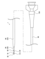
- FIG. 1 is an explanatory diagram illustrating an example of the overall configuration of a catheter according to a first embodiment.
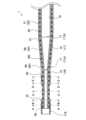
- FIG. 2 is an explanatory diagram illustrating a longitudinal cross section of a catheter tip portion.
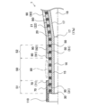
- FIG. 13 is an explanatory diagram illustrating a vertical cross section near a marker.
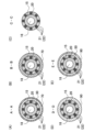
- FIG. 2 is an explanatory diagram illustrating a cross section of a catheter.
- 13 is an explanatory diagram illustrating a longitudinal section near a marker of a catheter according to a second embodiment.
- FIG. 13 is an explanatory diagram illustrating a longitudinal section near a marker of a catheter according to a third embodiment.
- FIG. 13 is an explanatory diagram illustrating a longitudinal section near a marker of a catheter according to a fourth embodiment.
- FIG. 13 is an explanatory diagram illustrating a longitudinal section near a marker of a catheter according to a fifth embodiment.
- Fig. 1 is an explanatory diagram illustrating the overall configuration of a catheter 1 of a first embodiment.
- Fig. 2 is an explanatory diagram illustrating a longitudinal cross section of the tip of the catheter 1.
- the end portion of each component of the catheter 1 located on the tip side will be referred to as the "tip”, and the portion including the “tip” and extending from the tip to the middle toward the rear end will be referred to as the "tip portion”.
- the end portion of each component located on the rear end side will be referred to as the "rear end”
- the portion including the "rear end” and extending from the rear end to the middle toward the tip side will be referred to as the "rear portion”.
- the catheter 1 is a medical device that is inserted into blood vessels, digestive organs, etc., and is used for treatment and diagnosis of the human body.
- the catheter 1 includes a shaft 15 (Figure 2), an intermediate tube 20, a distal tube 70, a proximal tube 90, a distal marker 30, a proximal marker 50, a distal tip 110, and a connector 120 ( Figure 1).
- the shaft 15 is a hollow member extending in the longitudinal direction of the catheter 1.
- the shaft 15 has a straight section 16 and a tapered section 17.
- the straight section 16 is a section of the shaft 15 whose outer diameter is approximately constant in the longitudinal direction of the shaft 15.
- the tapered section 17 is a section of the shaft 15 whose outer diameter increases from the tip side to the rear end side of the shaft 15.
- the outer diameter of the rear end 17b of the tapered section 17 is larger than the outer diameter of the tip 17a of the tapered section 17.
- the straight section 16 is provided on the tip side of the shaft 15, and the tapered section 17 is provided on the rear end side of the straight section 16.
- a lumen 18 is formed inside the shaft 15.
- the lumen 18 is a space that extends in the longitudinal direction of the shaft 15 by being surrounded by the inner circumference of the shaft 15.
- a guide wire, a delivery device for carrying an embolic substance used in the treatment of an aneurysm, and the like can pass through the lumen 18.
- the intermediate tube 20 is a hollow member that covers the outer circumference of the shaft 15. Inside the intermediate tube 20, a braid 21 is provided along the longitudinal direction of the catheter 1. The braid 21 is formed by weaving together four wires 22.
- the tip tube 70 is a hollow member that covers part of the outer periphery of the intermediate tube 20 and part of the outer periphery of the tip marker 30.
- the tip tube 70 is disposed on the outer periphery of the straight portion 16 of the shaft 15.
- the rear end tube 90 is a hollow member that covers part of the outer periphery of the intermediate tube 20 and the outer periphery of the rear end marker 50.
- the rear end tube 90 is disposed rearward of the tip end tube 70 in the longitudinal direction of the shaft 15.
- the rear end tube 90 has a first rear end tube 92 and a second rear end tube 93.
- the first rear end tube 92 covers the outer periphery of the tip side of the tapered portion 17 of the shaft 15.
- the second rear end tube 93 covers the outer periphery of the rear end side of the tapered portion 17 of the shaft 15.
- the boundary between the first rear end tube 92 and the second rear end tube 93 is called "boundary B0".
- the boundary B0 is between the tip 17a and rear end 17b of the tapered portion 17 of the shaft 15, and is located on the tip side of the intermediate position of the tapered portion 17 that is equidistant from the tip 17a and rear end 17b.
- the bending rigidity of the first rear end tube 92 is smaller than the bending rigidity of the second rear end tube 93. Therefore, the bending rigidity of the rear end tube 90, a portion covering the tip side of the tapered portion 17, is smaller than the bending rigidity of the portion covering the base end side.
- the bending rigidity of the portion of the rear end tube 90 covering the tip side of the tapered portion 17 and the bending rigidity of the portion covering the base end side are measured as follows.
- the rear end tube 90 is divided into four equal parts between the tip 17a of the tapered portion 17 and the middle position, and the average bending rigidity of the rear end tube 90 at each position is calculated.
- the rear end tube 90 is divided into four equal parts between the middle position of the tapered portion 17 and the rear end 17b, and the average bending rigidity of the rear end tube 90 at each position is calculated.
- the difference in bending rigidity between the first rear end tube 92 and the second rear end tube 93 can be set, for example, by forming the two tubes from materials with different hardness or by changing the thickness of the two tubes.
- the materials of the shaft 15, intermediate tube 20, tip tube 70, and rear tube 90 are not particularly limited, but may be, for example, nylon resins such as polyamide, polyolefins such as polyethylene, polypropylene, and ethylene-propylene copolymers, polyesters such as polyethylene terephthalate, thermoplastic resins such as polyvinyl chloride, ethylene-vinyl acetate copolymers, cross-linked ethylene-vinyl acetate copolymers, and polyurethanes, fluororesins such as polytetrafluoroethylene (PTFE), polyamide elastomers, polyolefin elastomers, polyurethane elastomers, silicone rubber, and latex rubber.
- nylon resins such as polyamide
- polyolefins such as polyethylene, polypropylene, and ethylene-propylene copolymers
- polyesters such as polyethylene terephthalate
- thermoplastic resins such as polyvinyl chloride, ethylene-vin
- the tip marker 30 is an annular member made of a material with low X-ray transmittance.
- the tip marker 30 is provided at the tip of the shaft 15. Specifically, the tip marker 30 is disposed on the outer periphery of the straight portion 16 of the shaft 15. "The tip marker 30 is provided at the tip of the shaft 15" means that at least a part of the tip marker 30 is at the same axial position as the tip of the shaft 15, and the tip marker 30 does not necessarily have to be directly connected to the tip of the shaft 15. Here, the tip marker 30 is indirectly fixed to the tip of the shaft 15 via the intermediate tube 20.
- the outer periphery of the tip of the tip marker 30 is covered by the tip tip 110, and the outer periphery of the rear end of the tip marker 30 is covered by the tip tube 70.
- the rear end marker 50 is an annular member formed of a material with low X-ray transmittance.
- the rear end marker 50 is provided at the tip of the shaft 15. Specifically, the rear end marker 50 is disposed on the outer periphery of the straight portion 16 of the shaft 15. "The rear end marker 50 is provided at the tip of the shaft 15" means that at least a part of the rear end marker 50 is at the same axial position as the tip of the shaft 15, and the rear end marker 50 does not necessarily have to be directly connected to the tip of the shaft 15.
- the rear end marker 50 is indirectly fixed to the tip of the shaft 15 via the intermediate tube 20.
- the rear end marker 50 is provided on the rear end side of the tip marker 30.
- the outer periphery of the rear end marker 50 is covered by the rear end tube 90.
- the shape of the leading end marker 30 and the trailing end marker 50 is not limited to annular, and may be, for example, a plate shape that covers only a portion of the outer circumference of the intermediate tube 20, or a coil shape as described in the third embodiment below.
- the materials of the leading end marker 30 and the trailing end marker 50 are not particularly limited, but may be, for example, gold, platinum, tungsten, or alloys containing these elements (for example, platinum-nickel alloys).
- the materials of the leading end marker 30 and the trailing end marker 50 may be, for example, resin materials formed by mixing a radiopaque material such as bismuth trioxide, tungsten, or barium sulfate with polyamide resin, polyolefin resin, polyester resin, polyurethane resin, silicone resin, or fluororesin.
- the distal tip 110 is a hollow member with a space that communicates with the lumen 18 of the shaft 15.
- the distal tip 110 is connected to the distal end of the shaft 15, the distal end of the intermediate tube 20, the distal end of the distal tube 70, and the distal end of the distal marker 30.
- the rear end of the distal tip 110 covers the outer periphery of the distal end of the distal marker 30.
- the material of the tip tip 110 is not particularly limited, but can be, for example, a resin material such as polyurethane, polyurethane elastomer, polyamide, or polyamide elastomer.
- the connector 120 is a member connected to the rear end of the rear end tube 90 and is used to connect the catheter 1 to other medical devices such as a syringe (not shown).
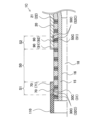
- FIG. 3 is an explanatory diagram illustrating a longitudinal cross section of the catheter 1 near the markers (30, 50).
- the distal tube 70 covers a portion of the outer periphery of the distal marker 30.
- the rear end 71 of the distal tube 70 is located further rearward than the rear end 31 of the distal marker 30.
- the rear tube 90 covers the outer periphery of the rear marker 50.
- the tip 91 of the rear tube 90 is located further distal than the tip 51 of the rear marker 50. As a result, the outer periphery of the rear marker 50 is not exposed to the outside.
- the rear end 71 of the tip tube 70 and the tip 91 of the rear tube 90 are spaced apart.
- the section between the rear end 71 of the tip tube 70 and the tip 91 of the rear tube 90 is called “section S0”.
- the gap 80 is formed along the outer periphery of the intermediate tube 20.
- the section from the tip of the tip marker 30 to the rear end 71 of the tip tube 70 is called “section S1".
- the section from the rear end of the rear marker 50 to the tip 91 of the rear tube 90 is called "section S2".
- Fig. 4 is an explanatory diagram illustrating a cross section of the catheter 1.
- Fig. 4 (A) to (E) respectively illustrate the A-A cross section, the B-B cross section, the C-C cross section, the D-D cross section, and the E-E cross section of Fig. 2.
- 4A is a cross section taken along line AA in FIG. 2, which is a cross section of the distal end of section S1 (FIG. 3).
- the outer periphery of the distal marker 30 is covered by the distal tube 70.
- 4B is a cross section taken along line B-B in FIG. 2, which is a cross section of the rear end side of section S1 (FIG. 3).
- FIG. 4A is a cross section taken along line AA in FIG. 2, which is a cross section of the distal end of section S1 (FIG. 3).
- 4B is a cross section taken along line B-B in FIG. 2, which is a cross section of the rear end side of section S1 (FI
- 4(C) is a cross section taken along line CC in FIG. 2, which is a cross section of section S0 (FIG. 3). As shown in FIG. 4(C), in section S0 (FIG. 3), the outer periphery of the intermediate tube 20 is exposed and is not covered by the distal tube 70 or the proximal tube 90. In other words, a gap 80 (FIG. 3) is formed along the outer periphery of the intermediate tube 20.
- 4(D) is a cross section taken along line D-D in FIG.
- FIG. 4(D) is a cross section of the tip side of section S2 (FIG. 3).
- FIG. 4(D) a portion in which the outer periphery of the intermediate tube 20 is covered by the rear end tube 90 is provided on the tip side of the tip 51 (FIG. 3) of the rear end marker 50.
- 4(E) is a cross section taken along line E-E in FIG. 2, which is a cross section of the rear end side of section S2 (FIG. 3).
- the outer periphery of the rear end marker 50 is covered by the rear end tube 90.
- the catheter 1 in section S1 is composed of a shaft 15, an intermediate tube 20, a tip tube 70, and a tip marker 30.
- the catheter 1 in section S2 is composed of a shaft 15, an intermediate tube 20, a rear end tube 90, and a rear end marker 50.
- the catheter 1 in section S0 does not have the tip tube 70, the rear end tube 90, the tip marker 30, or the rear end marker 50.
- the bending rigidity of the catheter 1 in section S0 is smaller than the bending rigidity of the catheter 1 in section S1 and the bending rigidity of the catheter 1 in section S2.
- the flexibility of the part between the tip tube 70 and the rear end tube 90 of the catheter 1 is high.
- the tubes (70, 90) and markers (30, 50) are not arranged in section S0, the outer diameter of the catheter 1 in section S0 is smaller than the outer diameter of the catheter 1 in section S1 and the outer diameter of the catheter 1 in section S2.
- the braid 21 is formed by a combination of two wires 22 wound in a first direction along the longitudinal direction of the intermediate tube 20, and two wires 22 wound in a second direction different from the first direction.
- the material of the wires 22 is not particularly limited, but for example, tungsten can be used.
- the rear end 71 of the tip tube 70 and the tip 91 of the rear tube 90 are spaced apart. Since the outer layer tube (70, 90) and the marker (30, 50) are not arranged in section S0, the bending rigidity of the catheter 1 in section S0 is smaller than the bending rigidity of the catheter 1 in sections (S1, S2) adjacent to section S0. In addition, the outer diameter of the catheter 1 in section S0 is smaller than the outer diameter of the catheter 1 in sections (S1, S2). This improves the flexibility of the tip of the catheter 1. Since section S0 is located between the tip marker 30 and the rear marker 50, the flexibility of the catheter 1 between the tip marker 30 and the rear marker 50 can be improved.
- the catheter 1 can be used to treat aneurysms.
- the distal marker 30 and the proximal marker 50 function to display the position of the distal end of the catheter 1 under X-ray fluoroscopy, and can also be used to align a delivery device for carrying an embolic substance used in treating aneurysms.
- the position of the markers (30, 50) confirms that the distal end of the catheter 1 has been placed near the treatment site, and the distal end of the delivery device can be positioned at an appropriate position near the treatment site by aligning the position of the marker (30, 50) with the marker provided at the distal end of the delivery device.
- the portion of the catheter 1 included in section S is advanced toward the end of the blood vessel along a guidewire that has been inserted into the blood vessel in advance. It may be difficult for the catheter 1 to advance inside the blood vessel following the guidewire due to resistance from the curved blood vessel, but the flexibility of the portion of the catheter 1 included in section S makes it easier to follow the guidewire.
- the tip marker 30 and the rear end marker 50 are provided on the straight section 16 of the shaft 15.
- the markers (30, 50) on the straight section 16 provided on the tip side of the catheter 1 it becomes easier to visually confirm the position of the tip of the catheter 1 inserted into the body under X-ray fluoroscopy.
- the bending stiffness of the first rear end tube 92 of the rear end tube 90 is smaller than the bending stiffness of the second rear end tube 93. This improves the flexibility of the tip side of the catheter 1.
- the portion where the bending stiffness of the rear end tube 90 changes (boundary B0) is located between the tip 17a and rear end 17b of the tapered section 17. This suppresses the change in bending stiffness of the catheter 1 in the straight section 16, making it easier for the straight section 16 to follow along the guidewire that has been previously inserted into the body.
- the catheter 1 has a distal tip 110 that is located distal to the distal marker 30 and adjacent to the distal marker 30. For example, by using a flexible material for the distal tip 110, the risk of the catheter 1 damaging the inside of the body can be reduced.
- a part of the shaft 15 is disposed between the rear end 71 of the distal tube 70 and the distal end 91 of the proximal tube 90 (section S0). This allows a lumen 18 to be provided in section S0 as well, making it easy to insert other medical devices into the body through the lumen 18.
- the rear end 71 of the distal tube 70 is located rearward of the rear end 31 of the distal marker 30, and the front end 91 of the rear tube 90 is located frontward of the front end 51 of the rear marker 50.
- the rear end 31 of the distal marker 30 is covered by the distal tube 70, and the front end 51 of the rear marker 50 is covered by the rear tube 90.
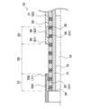
- Second Embodiment 5 is an explanatory diagram illustrating a longitudinal section of the catheter 1B of the second embodiment near the markers (30B, 50B).
- the catheter 1B differs from the catheter 1 of the first embodiment in that the markers (30B, 50B) are embedded in the intermediate tube 20.
- a description of the configuration of the catheter 1B that is common to the configuration of the catheter 1 will be omitted.
- the tip marker 30B and the rear marker 50B are embedded in the tip of the intermediate tube 20.
- a portion of the outer periphery of the tip marker 30B is covered by the tip tube 70.
- a portion of the outer periphery of the rear marker 50B is covered by the rear tube 90.
- Third Embodiment 6 is an explanatory diagram illustrating a longitudinal section of a catheter 1C of the third embodiment near the markers (30C, 50C).
- the catheter 1C is different from the catheter 1 of the first embodiment in that the markers (30C, 50C) are coil-shaped. A description of the configuration of the catheter 1C that is common to the configuration of the catheter 1 will be omitted.
- the tip marker 30C is a coil formed by winding the wire 32C in a spiral shape in the longitudinal direction of the catheter 1C.
- the rear end marker 50C is a coil formed by winding the wire 52C in a spiral shape in the longitudinal direction of the catheter 1C.
- the wire (32C, 52C) can be made of a radiopaque material, similar to the markers (30, 50) of the catheter 1 of the first embodiment described above.
- the tip tube 70 covers the outer periphery of the wire 32C, and the rear end tube 90 covers the outer periphery of the wire 52C.
- the coil-shaped markers (30C, 50C) can prevent the bending rigidity of the catheter 1C from being increased by the markers (30C, 50C).
- the catheter 1C can also improve the flexibility of the tip of the catheter 1C.
- Fourth Embodiment 7 is an explanatory diagram illustrating a longitudinal section of a catheter 1D of the fourth embodiment near the markers (30, 50).
- the catheter 1D differs from the catheter 1 of the first embodiment in that a distal tube 70D extends further toward the distal end than the distal end of the shaft 15. A description of the configuration of the catheter 1D that is common to the configuration of the catheter 1 will be omitted.
- the tip of the tip tube 70D is disposed further distal than the tip of the shaft 15, the tip of the intermediate tube 20, and the tip of the tip marker 30 in the longitudinal direction of the catheter 1D.
- the catheter 1D does not have the tip tip 110 of the catheter 1 of the first embodiment, the tip of the tip tube 70D can have the same function as the tip tip 110.
- the risk of the catheter 1D damaging the inside of the body can be reduced.
- the catheter 1D can also improve the flexibility of the tip of the catheter 1D.
- Fifth Embodiment 8 is an explanatory diagram illustrating a vertical cross section of the catheter 1E of the fifth embodiment near the markers (30, 50).
- the catheter 1E is different from the catheter 1 of the first embodiment in that the rear end 71E of the distal tube 70E and the distal end 91E of the rear end tube 90E (first rear end tube 92E) are tapered.
- a description of the configuration of the catheter 1E that is common to the configuration of the catheter 1 will be omitted.
- the thickness of the tip tube 70E is called “thickness t1" and the thickness of the rear tube 90E is called “thickness t2".
- the rear end 71E of the tip tube 70E has a tapered shape in which the thickness t1 gradually decreases from the tip side to the rear end side of the catheter 1E.
- the tip 91E of the rear tube 90E has a tapered shape in which the thickness t2 gradually decreases from the rear end side to the tip side of the catheter 1E.
- the rear end 71E of the tip tube 70E and the tip 91E of the rear tube 90E have a curved outer surface.
- the catheter 1E can also improve the flexibility of the tip of the catheter 1E.
- the tip markers (30, 30B, 30C) and the rear end markers (50, 50B, 50C) are provided on the straight portion 16 of the shaft 15.
- the tip markers (30, 30B, 30C) and the rear end markers (50, 50B, 50C) may be provided on the tapered portion 17 of the shaft 15.
- the catheters (1, 1B, 1C, 1D, 1E) of the first to fifth embodiments are configured by overlapping a shaft 15, an intermediate tube 20, a tip tube (70, 70D, 70E), and a rear tube (90, 90E).
- the catheters (1, 1B, 1C, 1D, 1E) may not have the shaft 15, and may not have the intermediate tube 20.
- the catheters (1, 1B, 1C, 1D, 1E) may be configured by a tip tube (70, 70D, 70E) covering the outer periphery of the tip marker (30, 30B, 30C) and a rear tube (90, 90E) covering the outer periphery of the rear marker (50, 50B, 50C).
- the rear end (71, 71E) of the distal tube (70, 70D, 70E) is located rearward of the rear end 31 of the distal marker (30, 30B, 30C), and the front end (91, 91E) of the rear tube (90, 90E) is located distal of the front end 51 of the rear marker (50, 50B, 50C).
- the rear end (71, 71E) of the distal tube (70, 70D, 70E) may be located distal of the rear end 31 of the distal marker (30, 30B, 30C), and the front end (91, 91E) of the rear tube (90, 90E) may be located rearward of the front end 51 of the rear marker (50, 50B, 50C).
Landscapes
- Health & Medical Sciences (AREA)
- Life Sciences & Earth Sciences (AREA)
- Biophysics (AREA)
- Pulmonology (AREA)
- Engineering & Computer Science (AREA)
- Anesthesiology (AREA)
- Biomedical Technology (AREA)
- Heart & Thoracic Surgery (AREA)
- Hematology (AREA)
- Animal Behavior & Ethology (AREA)
- General Health & Medical Sciences (AREA)
- Public Health (AREA)
- Veterinary Medicine (AREA)
- Media Introduction/Drainage Providing Device (AREA)
Priority Applications (1)
| Application Number | Priority Date | Filing Date | Title |
|---|---|---|---|
| US19/227,617 US20250295887A1 (en) | 2022-12-13 | 2025-06-04 | Catheter |
Applications Claiming Priority (2)
| Application Number | Priority Date | Filing Date | Title |
|---|---|---|---|
| JP2022198605A JP2024084369A (ja) | 2022-12-13 | 2022-12-13 | カテーテル |
| JP2022-198605 | 2022-12-13 |
Related Child Applications (1)
| Application Number | Title | Priority Date | Filing Date |
|---|---|---|---|
| US19/227,617 Continuation US20250295887A1 (en) | 2022-12-13 | 2025-06-04 | Catheter |
Publications (1)
| Publication Number | Publication Date |
|---|---|
| WO2024127750A1 true WO2024127750A1 (ja) | 2024-06-20 |
Family
ID=91484773
Family Applications (1)
| Application Number | Title | Priority Date | Filing Date |
|---|---|---|---|
| PCT/JP2023/032854 Ceased WO2024127750A1 (ja) | 2022-12-13 | 2023-09-08 | カテーテル |
Country Status (3)
| Country | Link |
|---|---|
| US (1) | US20250295887A1 (enExample) |
| JP (1) | JP2024084369A (enExample) |
| WO (1) | WO2024127750A1 (enExample) |
Citations (4)
| Publication number | Priority date | Publication date | Assignee | Title |
|---|---|---|---|---|
| US6702802B1 (en) * | 1999-11-10 | 2004-03-09 | Endovascular Technologies, Inc. | Catheters with improved transition |
| US20110054394A1 (en) * | 2002-02-04 | 2011-03-03 | Boston Scientific Scimed, Inc. | Bonding sleeve for a medical device |
| WO2019180928A1 (ja) * | 2018-03-23 | 2019-09-26 | 朝日インテック株式会社 | バルーンカテーテル |
| WO2022091372A1 (ja) * | 2020-10-30 | 2022-05-05 | 朝日インテック株式会社 | カテーテルおよびその製造方法 |
-
2022
- 2022-12-13 JP JP2022198605A patent/JP2024084369A/ja active Pending
-
2023
- 2023-09-08 WO PCT/JP2023/032854 patent/WO2024127750A1/ja not_active Ceased
-
2025
- 2025-06-04 US US19/227,617 patent/US20250295887A1/en active Pending
Patent Citations (4)
| Publication number | Priority date | Publication date | Assignee | Title |
|---|---|---|---|---|
| US6702802B1 (en) * | 1999-11-10 | 2004-03-09 | Endovascular Technologies, Inc. | Catheters with improved transition |
| US20110054394A1 (en) * | 2002-02-04 | 2011-03-03 | Boston Scientific Scimed, Inc. | Bonding sleeve for a medical device |
| WO2019180928A1 (ja) * | 2018-03-23 | 2019-09-26 | 朝日インテック株式会社 | バルーンカテーテル |
| WO2022091372A1 (ja) * | 2020-10-30 | 2022-05-05 | 朝日インテック株式会社 | カテーテルおよびその製造方法 |
Also Published As
| Publication number | Publication date |
|---|---|
| US20250295887A1 (en) | 2025-09-25 |
| JP2024084369A (ja) | 2024-06-25 |
Similar Documents
| Publication | Publication Date | Title |
|---|---|---|
| JP5075632B2 (ja) | 予め形状化された遠位先端部を有するカテーテル | |
| US10933220B2 (en) | Balloon catheter | |
| US20200276413A1 (en) | Catheter | |
| JPH06507566A (ja) | 剛性可変カテーテル | |
| US20210023339A1 (en) | Catheter With Embedded Core Wires | |
| EP2943244B1 (en) | Coronary guidewire | |
| WO2012014860A1 (ja) | 医療用カテーテル | |
| WO2024127750A1 (ja) | カテーテル | |
| JP2016154632A (ja) | 医療用長尺体 | |
| US20220105310A1 (en) | Hollow shaft and catheter | |
| JP2018064890A (ja) | カテーテル組立体 | |
| JP7715159B2 (ja) | ガイドエクステンションカテーテル | |
| US20250249205A1 (en) | Catheter | |
| US20250065082A1 (en) | Catheter | |
| US20240299703A1 (en) | Catheter | |
| WO2018074074A1 (ja) | カテーテル組立体 | |
| US20220152351A1 (en) | Catheter | |
| JP2025119195A (ja) | 医療機器用補助具、ガイドワイヤアッセンブリ及び医療機器アッセンブリ | |
| JP2025183963A (ja) | カテーテル | |
| WO2022158417A1 (ja) | カテーテル | |
| JP2023031608A (ja) | カテーテル | |
| JP2018064891A (ja) | カテーテル組立体 | |
| HK1211245B (en) | Coronary guidewire |
Legal Events
| Date | Code | Title | Description |
|---|---|---|---|
| 121 | Ep: the epo has been informed by wipo that ep was designated in this application |
Ref document number: 23903052 Country of ref document: EP Kind code of ref document: A1 |
|
| NENP | Non-entry into the national phase |
Ref country code: DE |
|
| 122 | Ep: pct application non-entry in european phase |
Ref document number: 23903052 Country of ref document: EP Kind code of ref document: A1 |