WO2024127458A1 - 空気調和装置及びその施工方法 - Google Patents
空気調和装置及びその施工方法 Download PDFInfo
- Publication number
- WO2024127458A1 WO2024127458A1 PCT/JP2022/045659 JP2022045659W WO2024127458A1 WO 2024127458 A1 WO2024127458 A1 WO 2024127458A1 JP 2022045659 W JP2022045659 W JP 2022045659W WO 2024127458 A1 WO2024127458 A1 WO 2024127458A1
- Authority
- WO
- WIPO (PCT)
- Prior art keywords
- indoor
- heat exchanger
- heat exchange
- refrigerant
- unit housing
- Prior art date
- Legal status (The legal status is an assumption and is not a legal conclusion. Google has not performed a legal analysis and makes no representation as to the accuracy of the status listed.)
- Ceased
Links
Images










Classifications
-
- F—MECHANICAL ENGINEERING; LIGHTING; HEATING; WEAPONS; BLASTING
- F24—HEATING; RANGES; VENTILATING
- F24F—AIR-CONDITIONING; AIR-HUMIDIFICATION; VENTILATION; USE OF AIR CURRENTS FOR SCREENING
- F24F1/00—Room units for air-conditioning, e.g. separate or self-contained units or units receiving primary air from a central station
- F24F1/0007—Indoor units, e.g. fan coil units
- F24F1/0059—Indoor units, e.g. fan coil units characterised by heat exchangers
- F24F1/0063—Indoor units, e.g. fan coil units characterised by heat exchangers by the mounting or arrangement of the heat exchangers
-
- F—MECHANICAL ENGINEERING; LIGHTING; HEATING; WEAPONS; BLASTING
- F24—HEATING; RANGES; VENTILATING
- F24F—AIR-CONDITIONING; AIR-HUMIDIFICATION; VENTILATION; USE OF AIR CURRENTS FOR SCREENING
- F24F1/00—Room units for air-conditioning, e.g. separate or self-contained units or units receiving primary air from a central station
- F24F1/0007—Indoor units, e.g. fan coil units
- F24F1/0068—Indoor units, e.g. fan coil units characterised by the arrangement of refrigerant piping outside the heat exchanger within the unit casing
-
- F—MECHANICAL ENGINEERING; LIGHTING; HEATING; WEAPONS; BLASTING
- F24—HEATING; RANGES; VENTILATING
- F24F—AIR-CONDITIONING; AIR-HUMIDIFICATION; VENTILATION; USE OF AIR CURRENTS FOR SCREENING
- F24F2130/00—Control inputs relating to environmental factors not covered by group F24F2110/00
- F24F2130/20—Sunlight
Definitions
- This disclosure relates to an air conditioning device and its installation method.
- an indoor heat exchanger installed indoors functions as both a condenser and an evaporator (see, for example, Patent Document 1).
- the indoor heat exchanger is composed of a cooling heat exchanger and a reheating exchanger.
- the cooling heat exchanger functions as an evaporator and cools the air that is sucked in.
- the reheating heat exchanger functions as a condenser and heats the air that is sucked in.
- piping through which a heat medium such as a refrigerant, water, antifreeze, or brine flows is connected to an indoor heat exchanger provided inside the indoor unit housing.
- a heat medium such as a refrigerant, water, antifreeze, or brine flows
- the piping may have to be extended or bent in order to connect to the indoor heat exchanger.
- extending or bending the piping increases the flow resistance of the heat medium, resulting in a problem of reduced performance of the air conditioner.
- This disclosure has been made against the background of the above-mentioned problems, and aims to provide an air conditioner and its construction method that makes it possible to install an indoor unit housing while suppressing the deterioration of the air conditioner's performance caused by the arrangement of the piping.
- the air conditioning device comprises a compressor and an outdoor heat exchanger provided inside an outdoor unit housing, an indoor heat exchanger and an indoor blower provided inside an indoor unit housing, and a heat medium pipe connected to the indoor heat exchanger and through which a heat medium flows that directly exchanges heat with the indoor air.
- the indoor heat exchanger has a first heat exchange section that heats the indoor air during dehumidification operation and a second heat exchange section that cools the indoor air during dehumidification operation to condense water vapor in the indoor air.
- the indoor heat exchanger is provided in the indoor unit housing in either a first mounting mode or a second mounting mode.
- the surface of the indoor heat exchanger that faces the airflow generated by the indoor blower differs between the first mounting mode and the second mounting mode. In both the first mounting mode and the second mounting mode, the second heat exchange section is provided below the first heat exchange section.
- the air conditioning apparatus installation method is an installation method for the above air conditioning apparatus, and includes a step of installing the indoor heat exchanger in an installation mode in which the length of the heat medium piping located between the outdoor unit housing and the indoor heat exchanger is shortened, out of the first and second installation modes.
- the indoor heat exchanger has a first heat exchange section that heats the indoor air during dehumidification operation and a second heat exchange section that cools the indoor air during dehumidification operation to condense water vapor in the indoor air.
- the indoor heat exchanger can be provided inside the indoor unit housing in either the first installation mode or the second installation mode.
- the surface of the indoor heat exchanger that faces the airflow is different in the first installation mode and the second installation mode, while the second heat exchange section is provided below the first heat exchange section in both the first installation mode and the second installation mode.
- the indoor unit housing can be installed while suppressing the deterioration of the performance of the air conditioner caused by the arrangement of the heat medium piping by installing the indoor heat exchanger inside the indoor unit housing in either the first installation mode or the second installation mode.
- FIG. 1 is a schematic configuration diagram of an air conditioning apparatus according to a first embodiment.
- 4A to 4C are diagrams for explaining a first mounting mode of the indoor heat exchanger according to the first embodiment.
- 6A to 6C are diagrams for explaining a second mounting mode of the indoor heat exchanger according to the first embodiment.
- 3 is a diagram for explaining a modified example of the indoor unit housing shown in FIG. 2 .
- FIG. 4 is a diagram for explaining a modified example of the indoor unit housing shown in FIG. 3 .
- FIG. 4A to 4C are diagrams for explaining a first mounting mode and a second mounting mode of the indoor heat exchanger according to the first embodiment.
- 3 is a diagram for explaining a heat transfer tube of an indoor heat exchanger according to the first embodiment.
- 5A to 5C are diagrams for explaining a heat transfer tube of another example of the indoor heat exchanger according to the first embodiment.
- 5A to 5C are diagrams for explaining the configurations of the side plates and the fixing plate when the indoor heat exchanger according to the first embodiment is in a first mounting mode.
- 10A to 10C are diagrams for explaining the configurations of the side plates and the fixing plate when the indoor heat exchanger according to the first embodiment is in a second mounting mode.
- 1 is a schematic bottom perspective view of an indoor unit housing for illustrating a side plate when the indoor heat exchanger according to Embodiment 1 is in a first mounting mode.
- FIG. 10 is a schematic bottom perspective view of the indoor unit housing for illustrating the side panels when the indoor heat exchanger according to the first embodiment is in a second mounting mode.
- FIG. FIG. 11 is a schematic bottom perspective view of the indoor unit housing for illustrating another example of a side plate when the indoor heat exchanger according to Embodiment 1 is in a second mounting mode.
- FIG. 4 is a schematic bottom perspective view of the indoor unit housing for illustrating a mounting mode of the side plate according to the first embodiment.
- FIG. 11 is a diagram for explaining an installation mode of an indoor unit housing according to Comparative Example 1.
- FIG. 11 is a diagram for explaining an installation mode of an indoor unit housing according to Comparative Example 2.
- FIG. 13 is a diagram for explaining a first branch portion according to the second embodiment.
- FIG. 13 is a diagram for explaining a first mounting mode of the indoor heat exchanger according to embodiment 3.
- FIG. 13 is a diagram for explaining a second mounting mode of the indoor heat exchanger according to embodiment 3.
- FIG. 13 is a diagram showing a schematic view of the air velocity distribution in a first mounting mode of the indoor heat exchanger according to embodiment 4.
- FIG. 13 is a diagram showing a schematic view of the air velocity distribution in a second mounting mode of the indoor heat exchanger according to the fourth embodiment.
- 13A to 13C are diagrams for explaining a first mode of an indoor blower according to a fifth embodiment.
- FIG. 13 is a diagram for explaining a second mode of the indoor blower according to the fifth embodiment.
- FIG. 13 is a diagram for explaining a second mode of the indoor blower according to the fifth embodiment.
- FIG. 13 is a diagram for explaining a first aspect of another example of an indoor blower according to embodiment 5.
- FIG. 13 is a diagram for explaining a second mode of another example of the indoor blower according to the fifth embodiment.
- FIG. 13 is a schematic configuration diagram of an air conditioning apparatus according to a sixth embodiment.
- FIG. 13 is a diagram for explaining an indoor heat exchanger according to a sixth embodiment.
- the air conditioner according to the present disclosure will be described below with reference to the drawings.
- the present disclosure is not limited to the following embodiments and their modifications, and can be modified in various ways without departing from the spirit of the present disclosure.
- the present disclosure also includes all combinations of possible configurations among the configurations shown in the following embodiments and modifications.
- terms indicating directions e.g., “up,” “down,” “right,” “left,” “front,” “rear,” etc.
- the same reference numerals are used to indicate the same or equivalent items, and this is common throughout the entire specification.
- the relative dimensional relationship or shape of each component may differ from the actual ones.
- the high and low levels of temperature and pressure in the following description are not determined in relation to absolute values, but are determined relatively in the state or operation of the air conditioner.
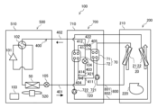
- FIG. 1 is a schematic diagram of an air-conditioning apparatus 100 according to embodiment 1.
- the solid arrows in Fig. 1 indicate the direction of refrigerant flow during cooling operation of the air-conditioning apparatus 100.
- the open arrows indicate airflow.
- the refrigerant flow is indicated by solid arrows, and the air flow is indicated by open arrows.
- the air conditioning device 100 of this embodiment includes an indoor unit 200, an outdoor unit 500, and a refrigerant piping 400.
- the indoor unit 200 includes an indoor unit housing 210. Inside the indoor unit housing 210, an indoor heat exchanger 20, a first throttling device 104, and an indoor blower 220 are provided.
- the outdoor unit 500 includes an outdoor unit housing 510. Inside the outdoor unit housing 510, a compressor 101, a flow path switching device 102, an outdoor heat exchanger 50, a second throttling device 105, an outdoor blower 520, and a control device 103 are provided.
- the compressor 101, the flow path switching device 102, the outdoor heat exchanger 50, the second throttling device 105, the indoor heat exchanger 20, and the first throttling device 104 are connected by the refrigerant piping 400 to form a refrigerant circuit in which the refrigerant, which is a heat medium, circulates.
- the indoor heat exchanger 20 includes a first heat exchange section 21 and a second heat exchange section 22.
- the refrigerant piping 400 includes a first refrigerant piping 401 provided between the outdoor unit housing 510 and the first heat exchange section 21, a second refrigerant piping 402 provided between the outdoor unit housing 510 and the second heat exchange section 22, and a third refrigerant piping 403 provided between the first heat exchange section 21 and the second heat exchange section 22.
- the first refrigerant piping 401 is connected to the first heat exchange section 21.
- the second refrigerant piping 402 is connected to the second heat exchange section 22.
- the third refrigerant piping 403 is connected to the first heat exchange section 21 and the second heat exchange section 22.
- the first throttling device 104 is provided in the third refrigerant piping 403.
- the second throttling device 105 is provided in the refrigerant piping 400 between the outdoor heat exchanger 50 and the first heat exchange section 21. Details of the first heat exchange section 21 and the second heat exchange section 22 will be described later. In the following description, when there is no need to distinguish between the first heat exchange section 21 and the second heat exchange section 22, they will be referred to simply as the "indoor heat exchanger 20". When the term “indoor heat exchanger 20" is used, it includes the first heat exchange section 21 and the second heat exchange section 22.
- refrigerant pipe 400 When there is no need to distinguish between the first refrigerant pipe 401, the second refrigerant pipe 402, and the third refrigerant pipe 403, they will be referred to simply as the "refrigerant pipe 400".
- refrigerant pipe 400 When the term “refrigerant pipe 400” is used, it includes at least one of the first refrigerant pipe 401, the second refrigerant pipe 402, and the third refrigerant pipe 403.
- the compressor 101 draws in a refrigerant, compresses it, and discharges it in a high-temperature, high-pressure state.
- the refrigerant compressed by the compressor 101 is discharged and flows into the flow path switching device 102.
- the compressor 101 is, for example, a rotary compressor, a scroll compressor, a screw compressor, or a reciprocating compressor.
- the flow path switching device 102 switches the direction of refrigerant flow in the refrigerant circuit.
- the flow path switching device 102 is, for example, a four-way valve.
- the flow path switching device 102 switches the direction of refrigerant flow during heating operation of the air conditioning device 100 and the direction of refrigerant flow during cooling operation and dehumidification operation.
- the flow path switching device 102 connects the discharge port of the compressor 101 to the outdoor heat exchanger 50 and connects the suction port of the compressor 101 to the indoor heat exchanger 20.
- the flow path switching device 102 connects the discharge port of the compressor 101 to the indoor heat exchanger 20 and connects the suction port of the compressor 101 to the outdoor heat exchanger 50.
- the first refrigerant piping 401 connecting the outdoor unit housing 510 and the first heat exchanger 21 is connected to the discharge side of the compressor 101 during cooling operation and dehumidification operation.
- the second refrigerant pipe 402 that connects the outdoor unit housing 510 and the second heat exchange section 22 is connected to the suction side of the compressor 101 during cooling operation and dehumidification operation.
- the outdoor heat exchanger 50 exchanges heat between the refrigerant flowing in from the refrigerant piping 400 and a heat exchange fluid such as air flowing through the outdoor heat exchanger 50.
- the outdoor heat exchanger 50 is configured, for example, as a fin-and-tube heat exchanger, a microchannel heat exchanger, a shell-and-tube heat exchanger, a heat pipe heat exchanger, a double-tube heat exchanger, or a plate heat exchanger.
- the outdoor heat exchanger 50 functions as an evaporator during heating operation.
- heat exchange takes place between the refrigerant that has flowed inside and the heat exchange fluid, causing the refrigerant to evaporate and vaporize.
- the outdoor heat exchanger 50 functions as a condenser during cooling and dehumidification operations.
- heat exchange occurs between the refrigerant that has flowed inside and the heat exchange fluid, causing the refrigerant to condense and liquefy.
- the outdoor blower 520 supplies air as a heat exchange fluid to the outdoor heat exchanger 50.
- the outdoor blower 520 is provided adjacent to the outdoor heat exchanger 50 in order to supply air. Supplying air from the outdoor blower 520 to the outdoor heat exchanger 50 increases the efficiency of heat exchange between the refrigerant and the outdoor air in the outdoor heat exchanger 50.
- the outdoor blower 520 is configured as a propeller fan, a line flow fan (registered trademark), or a multi-blade centrifugal fan, depending on the flow rate, static pressure, or other operating conditions.
- the heat exchange fluid supplied to the outdoor heat exchanger 50 may be water instead of air. In this case, a water pump or the like may be provided instead of the outdoor blower 520.
- the second throttling device 105 expands the refrigerant to reduce the pressure. That is, the second throttling device 105 functions as a pressure reducing valve or an expansion valve.
- the second throttling device 105 is, for example, configured with an electric expansion valve capable of adjusting the flow rate of the refrigerant.
- the second throttling device 105 is not limited to an electric expansion valve, and may be configured with a mechanical expansion valve that employs a diaphragm in the pressure receiving section.
- the second throttling device 105 does not have to be provided inside the outdoor unit housing 510.
- the second throttling device 105 may be provided inside the indoor unit housing 210.
- the second throttling device 105 may be provided in a diverter unit that divides the refrigerant to the multiple indoor units.
- the indoor heat exchanger 20 exchanges heat between the refrigerant flowing in from the refrigerant piping 400 and the heat exchange fluid flowing through the indoor heat exchanger 20.
- the indoor heat exchanger 20 is configured, for example, as a fin-and-tube heat exchanger, a microchannel heat exchanger, a shell-and-tube heat exchanger, a heat pipe heat exchanger, a double-tube heat exchanger, or a plate heat exchanger.
- both the first heat exchange section 21 and the second heat exchange section 22 function as condensers.
- heat is exchanged between the refrigerant that has flowed into the inside and the indoor air, causing the refrigerant to condense and liquefy.
- both the first heat exchange section 21 and the second heat exchange section 22 function as evaporators.
- heat exchange takes place between the refrigerant that has flowed into the inside and the indoor air, causing the refrigerant to evaporate and vaporize.
- the indoor heat exchanger 20 When in dehumidification operation, the indoor heat exchanger 20 has the first heat exchange section 21 functioning as a condenser and the second heat exchange section 22 functioning as an evaporator.
- the first heat exchange section 21 functioning as a condenser heat exchange takes place between the refrigerant that has flowed inside and the indoor air, causing the refrigerant to condense and liquefy.
- the second heat exchange section 22 functioning as an evaporator heat exchange takes place between the refrigerant that has flowed inside and the indoor air, causing the refrigerant to evaporate and vaporize.
- the indoor blower 220 supplies air as a heat exchange fluid to the indoor heat exchanger 20. Supplying air from the indoor blower 220 to the indoor heat exchanger 20 increases the efficiency of heat exchange between the refrigerant and the indoor air in the indoor heat exchanger 20.
- the indoor blower 220 is configured as a propeller fan, a line flow fan (registered trademark), or a multi-blade centrifugal fan, depending on the flow rate, static pressure, or other operating conditions.
- the first throttling device 104 expands the refrigerant to reduce its pressure. That is, the first throttling device 104 functions as a pressure reducing valve or an expansion valve.
- the first throttling device 104 is configured, for example, as an electric expansion valve capable of adjusting the flow rate of the refrigerant.
- the first throttling device 104 is not limited to an electric expansion valve, and may be configured as a mechanical expansion valve that employs a diaphragm in the pressure receiving section.
- the control device 103 controls the overall operation of the air conditioning device 100.
- the control device 103 is composed of dedicated hardware, or a CPU (Central Processing Unit) that executes programs stored in memory.
- the CPU is also called a central processing unit, processing unit, arithmetic unit, microprocessor, microcomputer, or processor.
- the control device 80 is dedicated hardware, the control device 103 is, for example, a single circuit, a composite circuit, an ASIC (Application Specific Integrated Circuit), an FPGA (Field-Programmable Gate Array), or a combination of these.
- Each of the functional units realized by the control device 103 may be realized by separate hardware, or each functional unit may be realized by a single piece of hardware.
- each function executed by the control device 103 is realized by software, firmware, or a combination of software and firmware.
- Software and firmware are written as programs and stored in memory.
- the CPU realizes each function of the control device 103 by reading and executing the programs stored in the memory.
- the memory is, for example, a non-volatile or volatile semiconductor memory such as RAM (Random Access Memory), ROM (Read Only Memory), flash memory, EPROM (Erasable Programmable Read Only Memory), or EEPROM (Electrically Erasable Programmable Read Only Memory).
- RAM Random Access Memory
- ROM Read Only Memory
- flash memory a non-volatile or volatile semiconductor memory
- EPROM Erasable Programmable Read Only Memory
- EEPROM Electrical Erasable Programmable Read Only Memory
- the control device 103 controls the compressor 101, the flow path switching device 102, the outdoor blower 520, the indoor blower 220, the first throttling device 104, and the second throttling device 105 during heating operation, cooling operation, and dehumidification operation.
- the control device 103 controls the flow path switching device 102 to switch the direction in which the refrigerant flows in the refrigerant circuit.
- the control device 103 may also control the compressor 101 to adjust the discharge amount of the compressed refrigerant.
- the control device 103 may also adjust the opening degree of the first throttling device 104 and the second throttling device 105 to adjust the flow rate of the refrigerant flowing through the refrigerant circuit.
- the high-temperature, high-pressure gas refrigerant compressed by the compressor 101 flows through the flow switching device 102 into the outdoor heat exchanger 50 functioning as a condenser.
- the high-temperature, high-pressure gas refrigerant that flows into the outdoor heat exchanger 50 is cooled and condensed by supplying heat to the outdoor air supplied by the outdoor blower 520, and flows out as a low-temperature liquid refrigerant.
- the liquid refrigerant that flows out of the outdoor heat exchanger 50 is decompressed by the second throttling device 105 to become a low-temperature, low-pressure two-phase gas-liquid refrigerant, and flows into the first heat exchanger 21 functioning as an evaporator.
- both the first heat exchanger 21 and the second heat exchanger 22 function as evaporators.
- the low-temperature, low-pressure two-phase gas-liquid refrigerant that flows into the first heat exchanger 21 absorbs heat from the indoor air supplied by the indoor blower 220 and evaporates.
- the refrigerant that flows out of the first heat exchange section 21 flows into the second heat exchange section 22 via the first throttling device 104 that is in a fully open state, or by bypassing the first throttling device 104.
- the refrigerant that flows into the second heat exchange section 22 evaporates and becomes a low-pressure gas refrigerant and flows out of the second heat exchange section 22.
- the refrigerant flows out of the indoor heat exchanger 20 as a low-pressure gas refrigerant.
- the low-pressure gas refrigerant that flows out of the indoor heat exchanger 20 passes through the flow switching device 102 and is then sucked into the compressor 101.
- the low-pressure gas refrigerant sucked into the compressor 101 is compressed again by the compressor 101 and is discharged as a high-temperature, high-pressure gas refrigerant. This cycle is repeated during cooling operation of the air conditioning device 100.
- the high-temperature, high-pressure gas refrigerant compressed by the compressor 101 flows through the flow switching device 102 into the outdoor heat exchanger 50 functioning as a condenser.
- the high-temperature, high-pressure gas refrigerant that flows into the outdoor heat exchanger 50 is cooled and condensed by supplying heat to the outdoor air supplied to the outdoor blower 520, and flows out as a gas-liquid two-phase refrigerant.
- the gas-liquid two-phase refrigerant that flows out of the outdoor heat exchanger 50 flows into the first heat exchanger 21 through the second throttling device 105 in a fully open state, or bypasses the second throttling device 105.
- the first heat exchanger 21 functions as a condenser
- the second heat exchanger 22 functions as an evaporator.
- the gas-liquid two-phase refrigerant that flows into the first heat exchanger 21 condenses while releasing heat to the indoor air supplied by the indoor blower 220, and becomes a low-temperature liquid refrigerant.
- the low-temperature liquid refrigerant flowing out of the first heat exchange unit 21 is decompressed by the first throttling device 104 until the saturation temperature is equal to or lower than the dew point temperature of the indoor air, and becomes a low-pressure gas-liquid two-phase refrigerant.
- the low-pressure gas-liquid two-phase refrigerant flowing out of the first throttling device 104 flows into the second heat exchange unit 22 functioning as an evaporator.
- the low-pressure gas-liquid two-phase refrigerant flowing into the second heat exchange unit 22 absorbs heat from the indoor air supplied by the indoor blower 220, evaporates, and becomes a low-pressure gas refrigerant.
- the low-pressure gas refrigerant flows out of the second heat exchange unit 22.
- the refrigerant flows out of the indoor heat exchanger 20 as a low-pressure gas refrigerant.
- the low-pressure gas refrigerant flowing out of the indoor heat exchanger 20 passes through the flow switching device 102 and is then drawn into the compressor 101.
- the low-pressure gas refrigerant drawn into the compressor 101 is compressed again by the compressor 101 and discharged as a high-temperature, high-pressure gas refrigerant. During the dehumidification operation of the air conditioner 100, this cycle is repeated.
- the air in the indoor space is humid, and the indoor blower 220 supplies the humid air drawn from the indoor space to the indoor heat exchanger 20. Upstream of the indoor heat exchanger 20, the humid air is divided and flows into the first heat exchange section 21 and the second heat exchange section 22.
- the air whose temperature has increased in the first heat exchange section 21 and the air whose temperature has decreased and been dehumidified in the second heat exchange section 22 join together downstream of the indoor heat exchanger 20. As a result, the decrease in the indoor temperature is suppressed, and dehumidified air is supplied to the room.
- the high-temperature, high-pressure gas refrigerant compressed by the compressor 101 flows through the flow switching device 102 into the indoor heat exchanger 20 functioning as a condenser.
- both the first heat exchanger 21 and the second heat exchanger 22 function as condensers.
- the high-temperature, high-pressure gas refrigerant that flows into the second heat exchanger 22 and the first heat exchanger 21 sequentially is cooled and condensed by supplying heat to the indoor air supplied by the indoor blower 220, and flows out of the first heat exchanger 21 as a low-temperature liquid refrigerant.
- the refrigerant flows out of the indoor heat exchanger 20 as a low-temperature liquid refrigerant.
- the liquid refrigerant that flows out of the indoor heat exchanger 20 is decompressed by the second throttling device 105 to become a low-temperature, low-pressure two-phase gas-liquid refrigerant, and flows into the outdoor heat exchanger 50 functioning as an evaporator.
- the low-temperature, low-pressure two-phase gas-liquid refrigerant that flows into the outdoor heat exchanger 50 absorbs heat from the outdoor air supplied by the outdoor blower 520. At this time, the liquid refrigerant in the gas-liquid two-phase state evaporates due to the absorbed heat, becoming a low-pressure gas refrigerant.
- the low-pressure gas refrigerant flows out of the outdoor heat exchanger 50, passes through the flow path switching device 102, and is then drawn into the compressor 101.
- the low-pressure gas refrigerant drawn into the compressor 101 is compressed again by the compressor 101 and discharged as a high-temperature, high-pressure gas refrigerant. This cycle is repeated during heating operation of the air conditioning apparatus 100.
- the first throttling device 104 may be in a closed state, or the refrigerant may bypass the first throttling device 104.
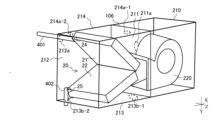
- FIG. 2 is a diagram for explaining a first mounting mode of the indoor heat exchanger 20 according to the first embodiment.
- Fig. 3 is a diagram for explaining a second mounting mode of the indoor heat exchanger 20 according to the first embodiment.
- Fig. 4 is a diagram for explaining a modified example of the indoor unit housing 210 shown in Fig. 2.
- Fig. 5 is a diagram for explaining a modified example of the indoor unit housing 210 shown in Fig. 3.
- Airflow direction X is the direction along the air flow, and is indicated by the symbol X in the drawings.
- the upstream side of airflow direction X is airflow upstream side X1
- the downstream side of airflow direction X is airflow downstream side X2.
- Vertical direction Y is the direction of gravity, and is indicated by the symbol Y in the drawings. In FIG. 2, the direction from the top of the paper to the bottom is the vertical direction Y.
- Depth direction Z is the depth direction of the indoor unit housing 210, and is indicated by the symbol Z in the drawings. In this embodiment, depth direction Z is the horizontal direction.
- the front side of the indoor unit housing 210 is indoor unit housing front side Z1
- the rear side of the indoor unit housing 210 is indoor unit housing rear side Z2.
- the indoor heat exchanger 20 includes the first heat exchange section 21 and the second heat exchange section 22.
- the first heat exchange section 21 has a first connection port 24 to which the first refrigerant piping 401 is connected.
- the second heat exchange section 22 has a second connection port 25 to which the second refrigerant piping 402 is connected.
- the second heat exchange section 22 is provided below the first heat exchange section 21 in the vertical direction Y.
- the first heat exchange section 21 and the second heat exchange section 22 are installed in the indoor unit housing 210 so that the cross section of the indoor heat exchanger 20 along the vertical direction Y and the airflow direction X is a horizontal V-shape.
- the indoor heat exchanger 20 is provided at a position facing the indoor blower 220 so that the airflow generated by the indoor blower 220 passes around the heat transfer tube of the indoor heat exchanger 20.
- the indoor heat exchanger 20 is provided downstream X2 in the airflow direction from the indoor blower 220.
- a filter 106 for capturing dust contained in the airflow may be provided between the indoor heat exchanger 20 and the indoor blower 220.
- first and a second mounting manner in which the indoor heat exchanger 20 is provided inside the indoor unit housing 210.
- the first and second mounting manners differ in the surface of the indoor heat exchanger 20 that faces the airflow generated by the indoor blower 220.
- the indoor heat exchanger 20 is provided so that the inner peripheral surface of the horizontal V-shape faces the airflow generated by the indoor blower 220.
- the indoor heat exchanger 20 is provided so that the outer peripheral surface of the horizontal V-shape faces the airflow generated by the indoor blower 220.
- the second heat exchange section 22 is provided below the first heat exchange section 21.
- the first refrigerant pipe 401 is inserted into the indoor unit housing 210 through the first opening 211a provided in the first wall surface 211 of the indoor unit housing 210.
- the second refrigerant pipe 402 is inserted into the indoor unit housing 210 through the second opening 211b provided in the first wall surface 211 of the indoor unit housing 210. That is, the refrigerant pipe 400 is inserted into the indoor unit housing 210 from the front side Z1 of the indoor unit housing.
- the second opening 211b is provided below the first opening 211a in the vertical direction Y.
- the first refrigerant pipe 401 inserted through the first opening 211a of the indoor unit housing 210 is connected to the first connection port 24 of the first heat exchange unit 21.
- the second refrigerant pipe 402 inserted through the second opening 211b of the indoor unit housing 210 is connected to the second connection port 25 of the second heat exchange unit 22.
- the first refrigerant pipe 401 is inserted into the indoor unit housing 210 through the third opening 212a provided in the second wall surface 212 of the indoor unit housing 210.
- the second refrigerant pipe 402 is inserted into the indoor unit housing 210 through the fourth opening 212b provided in the second wall surface 212 of the indoor unit housing 210. That is, the refrigerant pipe 400 is inserted into the indoor unit housing 210 from the rear side Z2 of the indoor unit housing.
- the fourth opening 212b is provided below the third opening 212a in the vertical direction Y.
- the first refrigerant pipe 401 inserted through the third opening 212a of the indoor unit housing 210 is connected to the first connection port 24 of the first heat exchange unit 21.
- the second refrigerant pipe 402 inserted through the fourth opening 212b of the indoor unit housing 210 is connected to the second connection port 25 of the second heat exchange unit 22.
- the first wall surface 211 and the second wall surface 212 of the indoor unit housing 210 face each other.
- openings when there is no need to distinguish between the first opening 211a, the second opening 211b, the third opening 212a, and the fourth opening 212b, they will be simply referred to as "openings".
- first refrigerant pipe 401 and the second refrigerant pipe 402 of this embodiment are not limited to the example in which they are inserted into the same wall surface of the indoor unit housing 210 shown in Figures 2 and 3, and may be inserted into different wall surfaces.
- the first refrigerant pipe 401 may be inserted into the indoor unit housing 210 along the depth direction Z
- the second refrigerant pipe 402 may be inserted into the indoor unit housing 210 along the vertical direction Y.
- the first refrigerant pipe 401 is inserted into the first opening 211a provided in the first wall surface 211 of the indoor unit housing 210.
- the second refrigerant pipe 402 is inserted into the second opening 213b-1 provided in the bottom surface 213 of the indoor unit housing 210 in the opposite direction to the vertical direction Y. Then, in the second installation mode, as shown in Figure 5, the first refrigerant pipe 401 is inserted into the third opening 212a provided in the second wall surface 212 of the indoor unit housing 210. The second refrigerant pipe 402 is inserted into a fourth opening 213b-2 provided in the bottom surface 213 of the indoor unit housing 210 in the opposite direction to the vertical direction Y. In this way, in each of the first and second mounting modes, the first refrigerant pipe 401 and the second refrigerant pipe 402 are inserted into adjacent wall surfaces of the indoor unit housing 210. Note that the second refrigerant pipe 402 is inserted into the same bottom surface 213 in both the first and second mounting modes, but the insertion position differs between the first and second mounting modes.
- the indoor unit housing 210 may have the first opening 214a-1 and the third opening 214a-2 shown in Figures 4 and 5 instead of the first opening 211a and the third opening 212a shown in Figures 2 and 3. That is, the indoor unit housing 210 may have the second opening 211b and the fourth opening 212b shown in Figures 2 and 3, and the first opening 214a-1 and the third opening 214a-2 shown in Figures 4 and 5.
- the first refrigerant piping 401 may be inserted into the indoor unit housing 210 along the vertical direction Y
- the second refrigerant piping 402 may be inserted into the indoor unit housing 210 along the depth direction Z.
- the first refrigerant piping 401 is inserted into the first opening 214a-1 provided on the top surface 214 of the indoor unit housing 210 in the vertical direction Y.
- the second refrigerant pipe 402 is inserted into the second opening 211b provided in the first wall surface 211.
- the first refrigerant pipe 401 is inserted into the third opening 214a-2 provided in the top surface 214 of the indoor unit housing 210 in the vertical direction Y.
- the second refrigerant pipe 402 is inserted into the fourth opening 212b provided in the second wall surface 212.
- the first refrigerant pipe 401 and the second refrigerant pipe 402 are inserted into the adjacent wall surfaces of the indoor unit housing 210.
- the first refrigerant pipe 401 is inserted into the same top surface 214 in both the first mounting mode and the second mounting mode, but the insertion position differs between the first mounting mode and the second mounting mode.
- FIG. 6 is a diagram for explaining the first mounting mode and the second mounting mode of the indoor heat exchanger 20 according to embodiment 1.
- FIG. 6 is a schematic diagram of the indoor heat exchanger 20 in the first mounting mode and the indoor heat exchanger 20 in the second mounting mode projected onto the first wall surface 211 of the indoor unit housing 210 from the rear side Z2 of the indoor unit housing toward the front side Z1 of the indoor unit housing.
- FIG. 6 is a schematic diagram of the indoor heat exchanger 20 in the first mounting mode and the indoor heat exchanger 20 in the second mounting mode projected onto the first wall surface 211 of the indoor unit housing 210 from the rear side Z2 of the indoor unit housing toward the front side Z1 of the indoor unit housing.
- FIG. 6 is a diagram showing a first projection view obtained by projecting the indoor heat exchanger 20 in the first mounting mode horizontally onto the first wall surface 211 and a second projection view obtained by projecting the indoor heat exchanger 20 in the second mounting mode horizontally onto the first wall surface 211, superimposed on each other.
- the indoor heat exchanger 20, the first heat exchange section 21, the second heat exchange section 22, the first connection port 24, and the second connection port 25 in the first installation mode may be referred to as the indoor heat exchanger 20a, the first heat exchange section 21a, the second heat exchange section 22a, the first connection port 24a, and the second connection port 25a, respectively.
- the indoor heat exchanger 20, the first heat exchange section 21, the second heat exchange section 22, the first connection port 24, and the second connection port 25 in the second installation mode may be referred to as the indoor heat exchanger 20b, the first heat exchange section 21b, the second heat exchange section 22b, the first connection port 24b, and the second connection port 25b, respectively.
- the first virtual point VP1a is a point in the first projection drawing when an arbitrary point of the first heat exchange section 21 is projected in the first mounting manner
- the second virtual point VP1b is a point in the second projection drawing when the arbitrary point is projected in the second mounting manner.
- the straight line connecting the first virtual point VP1a and the second virtual point VP1b is defined as the first virtual line VL1.
- the third virtual point VP2a is a point in the first projection drawing when an arbitrary point of the second heat exchange section 22 is projected in the first mounting manner
- the fourth virtual point VP2b is a point in the second projection drawing when the arbitrary point is projected in the second mounting manner.
- the straight line connecting the third virtual point VP2a and the fourth virtual point VP2b is defined as the second virtual line VL2.
- the fifth virtual point VP3a is a point in the first projection drawing in which the center of the first connection port 24 is projected in the first mounting mode
- the sixth virtual point VP3b is a point in the second projection drawing in which the center is projected in the second mounting mode.
- the straight line connecting the fifth virtual point VP3a and the sixth virtual point VP3b is the third virtual line VL3.
- the seventh virtual point VP4a is a point in the first projection drawing in which the center of the second connection port 25 is projected in the first mounting mode
- the eighth virtual point VP4b is a point in the second projection drawing in which the center is projected in the second mounting mode.
- the straight line connecting the seventh virtual point VP4a and the eighth virtual point VP4b is the fourth virtual line VL4.
- the first virtual line VL1, the second virtual line VL2, the third virtual line VL3, and the fourth virtual line VL4 are parallel to each other.
- FIG. 7 is a diagram for explaining the heat transfer tubes of the indoor heat exchanger 20 according to embodiment 1.
- FIG. 8 is a diagram for explaining another example of the heat transfer tubes of the indoor heat exchanger 20 according to embodiment 1.
- the heat transfer tubes of the indoor heat exchanger 20 may be circular tubes 30 as shown in FIG. 7, or flat tubes 31 as shown in FIG. 8.
- the first heat exchange section 21 and the second heat exchange section 22 each have a diverter header 28 and a merging header 29.
- the diverter header 28 of the first heat exchange section 21 has a first connection port 24, and the merging header 29 of the second heat exchange section 22 has a second connection port 25.
- the first refrigerant pipe 401 is connected to the first connection port 24 of the diverter header 28.
- the second refrigerant pipe 402 is connected to the second connection port 25 of the merging header 29.
- the merging header 29 of the first heat exchange section 21 and the diverter header 28 of the second heat exchange section 22 are connected by a third refrigerant pipe 403.
- the third refrigerant pipe 403 is provided with a first throttling device 104.
- Fig. 9 is a diagram for explaining the configuration of the side plate 230 and the fixing plate 240 when the indoor heat exchanger 20 according to the first embodiment is in a first attachment mode.
- Fig. 10 is a diagram for explaining the configuration of the side plate 230 and the fixing plate 240 when the indoor heat exchanger 20 according to the first embodiment is in a second attachment mode.
- the first heat exchange section 21 and the second heat exchange section 22 of the indoor heat exchanger 20 are fixed and integrated by a fixing plate 240, as shown in Figs. 9 and 10.
- the fixing plate 240 is a triangular plate-like member.
- the fixing plate 240 is attached to the first heat exchange section 21 and the second heat exchange section 22 so as to connect the opposing surfaces of the first heat exchange section 21 and the second heat exchange section 22.
- the position inside the indoor unit housing 210 changes depending on the first and second mounting modes of the indoor heat exchanger 20.
- each of the first heat exchange section 21 and the second heat exchange section 22 has a protruding portion for screwing the fixing plate 240.
- the method of attaching the fixing plate 240 to the first heat exchange section 21 and the second heat exchange section 22 is not particularly limited.
- the fixing plate 240 may be connected to the first heat exchange section 21 and the second heat exchange section 22 by adhesive or the like.
- the indoor heat exchanger 20 in the first mounting mode shown in FIG. 9 is rotated 180 degrees around the imaginary axis of rotation AX extending vertically upward to obtain the second mounting mode shown in FIG. 10.
- the indoor heat exchanger 20 in the second mounting mode shown in FIG. 10 is rotated 180 degrees around the imaginary axis of rotation AX to obtain the first mounting mode shown in FIG. 9.
- the fixing plate 240 located on the front side Z1 of the indoor unit housing in the first mounting mode is located on the rear side Z2 of the indoor unit housing in the second mounting mode as shown in FIG. 10.
- an opening may be provided in the indoor unit housing 210 so that the indoor heat exchanger 20 integrated with the fixing plate 240 can be removed from inside the indoor unit housing 210.
- at least one of the first wall surface 211 or the second wall surface 212 of the indoor unit housing 210 may be made removable from the indoor unit housing 210 so that the indoor heat exchanger 20 integrated with the fixing plate 240 can be removed from inside the indoor unit housing 210.
- the second heat exchange section 22 is attached with a side plate 230 as shown in Figs. 9 and 10.
- the side plate 230 is a member for fixing the indoor heat exchanger 20 to the indoor unit housing 210.
- the side plate 230 is a triangular plate member.
- the part where the side plate 230 is fixed to the bottom surface 213 of the indoor unit housing 210 is called the side plate fixing part 231.
- the side plate fixing part 231 may protrude from the plate member in a direction intersecting with the flat plate surface of the plate member of the side plate 230.
- the side plate fixing part 231 which is in surface contact with the bottom surface 213 of the indoor unit housing 210, is fixed to the indoor unit housing 210, thereby fixing the second heat exchange section 22 to the indoor unit housing 210.
- the position where the side plate 230 is fixed to the indoor unit housing 210 differs between the first mounting mode and the second mounting mode of the indoor heat exchanger 20.
- Figure 11 is a schematic bottom perspective view of the indoor unit housing 210 for explaining the side plate 230 when the indoor heat exchanger 20 according to embodiment 1 is in a first mounting state.
- Figure 12 is a schematic bottom perspective view of the indoor unit housing 210 for explaining the side plate 230 when the indoor heat exchanger 20 according to embodiment 1 is in a second mounting state.
- Figure 13 is a schematic bottom perspective view of the indoor unit housing 210 for explaining another example of the side plate 230 when the indoor heat exchanger 20 according to embodiment 1 is in the second mounting state.
- Figure 14 is a schematic bottom perspective view of the indoor unit housing 210 for explaining the mounting state of the side plate 230 according to embodiment 1.
- the side plate 230 and the side plate fixing portion 231 in the first mounting state of the indoor heat exchanger 20 may be referred to as the side plate 230a and the side plate fixing portion 231a, respectively.
- the side plate 230 and the side plate fixing portion 231 in the second mounting mode of the indoor heat exchanger 20 may be referred to as the side plate 230b and the side plate fixing portion 231b, respectively.
- the side plate 230 may include the side plate fixing portion 231.
- Figures 11 to 13 are views of the side plate 230 and the second heat exchange portion 22 viewed from the bottom surface 213 of the indoor unit housing 210 along the rotation axis AX shown in Figures 9 and 10.
- Figure 11 shows the side plate 230a
- Figures 12 and 13 show the side plate 230b.
- the side plate 230 in the first mounting mode, is located on the front side Z1 of the indoor unit housing. Also, the side plate fixing portion 231 protrudes toward the front side Z1 of the indoor unit housing. In the second mounting mode of the indoor heat exchanger 20, the side plate 230b can be fixed to the front side Z1 of the indoor unit housing or to the rear side Z2 of the indoor unit housing.
- Figure 12 shows the state in which the side plate 230 removed from the second heat exchange section 22a shown in Figure 11 is rotated 180 degrees around the vertical direction and attached to the underside of the second heat exchange section 22b.
- the side plate 230b is fixed to the front side Z1 of the indoor unit housing with the side plate fixing portion 231b protruding toward the rear side Z2 of the indoor unit housing.
- Figure 13 shows the state in which the second heat exchange section 22a and the side plate 230 shown in Figure 11 are rotated 180 degrees around the vertical direction as a single unit.
- the side plate 230b is fixed to the rear side Z2 of the indoor unit housing with the side plate fixing portion 231b protruding toward the rear side Z2 of the indoor unit housing.
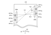
- FIG. 14 is a bottom perspective view of the indoor unit housing 210 along the rotation axis AX (see FIG. 9), showing the side plate 230a and the side plate 230b.
- three arbitrary points of the side plate 230a in the first mounting embodiment are shown as the first point PPT1a, the second point PPT2a, and the third point PPT3a, respectively.
- the three arbitrary points in the second mounting embodiment are shown as the first point PPT1b, the second point PPT2b, and the third point PPT3b.
- the imaginary line connecting the first point PPT1a and the first point PPT1b is the first imaginary line SL1.
- the imaginary line connecting the second point PPT2a and the second point PPT2b is the second imaginary line SL2.
- the virtual line connecting the third point PPT3a and the third point PPT3b is the third virtual line SL3.
- the indoor heat exchanger 20 is disposed so that the first virtual line SL1, the second virtual line SL2, and the third virtual line SL3 intersect at the virtual intersection point VO.
- the position of the virtual intersection point VO is the same as the position of the virtual rotation axis AX.
- Fig. 15 is a diagram for explaining the installation mode of the indoor unit housing according to Comparative Example 1.
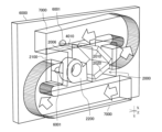
- Fig. 16 is a diagram for explaining the installation mode of the indoor unit housing according to Comparative Example 2.
- Comparative Example 1 shown in FIG. 15 will be described.
- Indoor unit housing 2100 of Comparative Example 1 is provided with indoor heat exchanger 2000, indoor blower 2200, and filter 2006.
- Indoor heat exchanger 2000 has first heat exchange section 2010 and second heat exchange section 2020.
- First refrigerant pipe 4010 is connected to first connection port 2400 of first heat exchange section 2010, and second refrigerant pipe 4020 is connected to second heat exchange section 2020.
- First refrigerant pipe 4010 and second refrigerant pipe 4020 are connected to an outdoor unit (not shown) provided outside the room through wall hole 6001 provided in wall 6000.
- first refrigerant piping 4010 and the second refrigerant piping 4020 it is necessary to extend the first refrigerant piping 4010 and the second refrigerant piping 4020 and then perform additional bending processing.
- the flow resistance of the refrigerant pipe between the indoor heat exchanger 2000 and the compressor increases, the refrigerant intake pressure of the compressor decreases, and the intake refrigerant density decreases. This reduces the refrigerant circulation flow rate in the air conditioning device, leading to a decrease in air conditioning capacity.
- Comparative Example 1 in order to avoid the extension and bending of the first refrigerant piping 4010 and the second refrigerant piping 4020, it is possible to change the arrangement of the indoor heat exchanger 2000 so that the first connection port 2400 and the second connection port 2500 face the first refrigerant piping 4010 and the second refrigerant piping 4020. That is, in FIG. 15, the indoor heat exchanger 2000 may be installed so that the first connection port 2400 and the second connection port 2500 are located on the rear side Z2 of the indoor unit housing.
- the second heat exchanger 2020 is provided above the first heat exchanger 2010.
- the second heat exchange unit 2020 functions as an evaporator
- the condensed water flows into the first heat exchange unit 2010 located below.
- the first heat exchange unit 2010 functions as a condenser, so when the condensed water flows in, the efficiency of heat exchange in the first heat exchange unit 2010 decreases, and the temperature of the air sent from the first heat exchange unit 2010 decreases. For this reason, the indoor temperature decreases during dehumidification operation, and as a result, the dehumidification performance of the air conditioner decreases.
- Comparative Example 1 in order to avoid the extension and bending of the first refrigerant pipe 4010 and the second refrigerant pipe 4020, it is also possible to change the arrangement direction of the indoor unit housing 2100 and position the first connection port 2400 and the second connection port 2500 on the rear side Z2 of the indoor unit housing. That is, in FIG. 15, the indoor unit housing 2100 may be arranged so that the indoor blower 2200 is located on the left side of the paper and the indoor heat exchanger 2000 is located on the right side of the paper. However, in this case, the direction of the airflow generated by the indoor blower 2200 is reversed, so the conditions of the airflow path of the space in which the air conditioner is installed may not be met.
- the direction of the airflow generated by the indoor blower 2200 cannot be changed because it leads to poor heat accommodation design and the release of dust into the indoor space.
- the conditions for installing the indoor blower 2200 in the air passage are not met, so the orientation of the indoor unit housing 2100 cannot be changed.
- the airflow duct 7000 is provided to redirect the airflow generated by the indoor blower 2200. Since the airflow duct 7000 can prevent the airflow generated by the indoor blower 2200 from being reversed, the installation direction of the indoor unit housing 2100 can be changed without extending or bending the first refrigerant piping 4010 and the second refrigerant piping 4020.
- the airflow duct 7000 when the airflow duct 7000 is provided as in the comparative example 2, a space for installing the airflow duct 7000 is required. In addition, including the airflow duct 7000 increases the size of the air conditioning device. In addition, the path through which the airflow supplied from the indoor blower 2200 travels becomes longer, so the flow resistance of the airflow reduces the volume of air sent, leading to a decrease in air conditioning capacity.
- the indoor heat exchanger 20 can be installed inside the indoor unit housing 210 by selecting either the first or second installation mode. Therefore, when installing the indoor unit housing 210 in the space shown in FIG. 15, the indoor heat exchanger 20 can be installed inside the indoor unit housing 210 in the second installation mode (see FIG. 3). Also, in this embodiment, in both the first and second installation modes of the indoor heat exchanger 20, the second heat exchange section 22 is provided below the first heat exchange section 21. Therefore, even if condensation occurs in the second heat exchange section 22 functioning as an evaporator during dehumidification operation, it does not flow into the first heat exchange section 21 functioning as a condenser.
- the second heat exchange section 22 exchanges heat between the refrigerant at or below the dew point temperature of the indoor air temperature and the indoor air, so that condensation occurs on the outside of the heat transfer tube.
- the condensation that adheres to the heat transfer tube in the second heat exchange section 22 flows down the refrigerant piping 400 using gravity as a driving force, into a drainage path (not shown) provided below, and is discharged outside the indoor unit housing 210.
- the air conditioning device 100 can select the mounting mode of the indoor heat exchanger 20 from the first mounting mode or the second mounting mode. Therefore, even if there is a limit to the space in which the indoor unit housing 210 is installed, the refrigerant piping 400 can be connected to the indoor heat exchanger 20 without both or either of the extension of the refrigerant piping 400 and bending of the refrigerant piping 400. In addition, in both the first mounting mode and the second mounting mode, the indoor heat exchanger 20 does not reduce the air conditioning capacity during dehumidification operation because the second heat exchange section 22 is provided below the first heat exchange section 21.
- the indoor unit housing 210 is not subject to the space limit for installing the indoor unit housing 210, and can be installed while suppressing the deterioration of the performance of the air conditioning device 100 caused by the arrangement of the refrigerant piping 400.
- the air conditioning apparatus 100 includes a compressor 101 and an outdoor heat exchanger 50 provided inside the outdoor unit housing 510, an indoor heat exchanger 20 and an indoor blower 220 provided inside the indoor unit housing 210, and refrigerant piping 400 connected to the indoor heat exchanger 20 as a heat medium piping through which a refrigerant flows as a heat medium that directly exchanges heat with the indoor air.
- the heat medium piping is part of the refrigerant piping 400.
- the indoor heat exchanger 20 has a first heat exchange section 21 that heats the indoor air during dehumidification operation, and a second heat exchange section 22 that cools the indoor air during dehumidification operation to condense water vapor in the indoor air.
- the indoor heat exchanger 20 is installed in the indoor unit housing 210 in either the first or second installation manner, and the surface of the indoor heat exchanger 20 facing the airflow generated by the indoor blower 220 is different between the first and second installation manners. In both the first and second installation manners, the second heat exchange section 22 is installed below the first heat exchange section 21.
- the refrigerant piping 400 through which the refrigerant flows as a heat medium connects the first throttling device 104 installed inside the indoor unit housing 210, the compressor 101, the outdoor heat exchanger 50, the indoor heat exchanger 20, and the first throttling device 104.
- the first heat exchange section 21 of the indoor heat exchanger 20 functions as a condenser during dehumidification operation
- the second heat exchange section 22 of the indoor heat exchanger 20 functions as an evaporator during dehumidification operation.
- the indoor heat exchanger 20 having a first heat exchange section 21 that functions as a condenser during dehumidification operation and a second heat exchange section 22 that functions as an evaporator during dehumidification operation can be provided inside the indoor unit housing 210 in either a first installation mode or a second installation mode. And, while the surface of the indoor heat exchanger 20 that faces the airflow is different between the first installation mode and the second installation mode, in both the first installation mode and the second installation mode, the second heat exchange section 22 is provided below the first heat exchange section 21. Therefore, the indoor heat exchanger 20 can be installed in the indoor unit housing 210 by selecting an installation mode that does not require at least one of the extension and bending of the refrigerant piping 400.
- the indoor heat exchanger 20 can be installed in the indoor unit housing 210 in either the first or second installation manner, thereby suppressing the deterioration of the performance of the air conditioning device 100 caused by the placement of the refrigerant piping 400 and allowing the indoor unit housing 210 to be installed.
- the second heat exchange section 22 is provided below the first heat exchange section 21. Therefore, when the air conditioning device 100 is in dehumidification operation, condensation water generated in the second heat exchange section 22, which functions as an evaporator, does not enter the first heat exchange section 21. Therefore, there is no difference in air conditioning capacity between the first and second mounting modes of the indoor heat exchanger 20 when the air conditioning device 100 is in dehumidification operation.
- the refrigerant piping 400 includes a first refrigerant piping 401 provided between the outdoor unit housing 510 and the first heat exchange unit 21, and a second refrigerant piping 402 provided between the outdoor unit housing 510 and the second heat exchange unit 22.
- the indoor unit housing 210 has a first wall surface 211 having a first opening 211a through which the first refrigerant piping 401 passes in the first mounting mode and a second opening 211b through which the second refrigerant piping 402 passes, and a second wall surface 212 having a third opening 212a through which the first refrigerant piping 401 passes in the second mounting mode and a fourth opening 212b through which the second refrigerant piping 402 passes.
- the first wall surface 211 and the second wall surface 212 face each other.
- the refrigerant piping 400 passes through either the first wall surface 211 or the second wall surface 212 facing the indoor unit housing 210 and is connected to the indoor heat exchanger 20. That is, in the first mounting mode of the indoor heat exchanger 20, the first refrigerant piping 401 is connected to the first connection port 24 of the first heat exchange section 21 through the first opening 211a of the first wall surface 211, and the second refrigerant piping 402 is connected to the second connection port 25 of the second heat exchange section 22 through the second opening 211b of the first wall surface 211.
- the first refrigerant piping 401 is connected to the first connection port 24 of the first heat exchange section 21 through the third opening 212a of the second wall surface 212
- the second refrigerant piping 402 is connected to the second connection port 25 of the second heat exchange section 22 through the fourth opening 212b of the second wall surface 212.
- the indoor heat exchanger 20 may be installed in either the first or second mounting manner, depending on whether the wall surface of the indoor unit housing 210 facing the ends of the first refrigerant piping 401 and the second refrigerant piping 402 extending from the outdoor unit housing 510 side is the first wall surface 211 or the second wall surface 212.
- the refrigerant piping 400 can be connected to the indoor heat exchanger 20 from the opposing first wall surface 211 or second wall surface 212 of the indoor unit housing 210 without changing the installation direction of the indoor unit housing 210 and without extending or bending the first refrigerant piping 401 and the second refrigerant piping 402. Therefore, in a space where the arrangement direction of the indoor unit housing 210 cannot be selected, the indoor unit housing 210 can be installed while suppressing the deterioration of the performance of the air conditioning device 100 caused by the arrangement of the refrigerant piping 400.
- the refrigerant piping 400 includes a first refrigerant piping 401 provided between the outdoor unit housing 510 and the first heat exchange unit 21, and a second refrigerant piping 402 provided between the outdoor unit housing 510 and the second heat exchange unit 22.
- the indoor unit housing 210 has a first wall surface 211 having a first wall surface opening through which one of the first refrigerant piping 401 and the second refrigerant piping 402 passes, and in the second mounting mode, a second wall surface 212 having a second wall surface opening through which the one of the first refrigerant piping 401 and the second refrigerant piping 402 passes, and a third wall surface having a third wall surface opening and a fourth wall surface opening through which the other of the first refrigerant piping 401 and the second refrigerant piping 402 passes.
- the first wall surface 211 and the second wall surface 212 face each other and are connected by the third wall surface.
- the first wall opening is either the first opening 211a through which the first refrigerant pipe 401 passes or the second opening 211b through which the second refrigerant pipe 402 passes.
- the second wall opening is either the third opening 212a through which the first refrigerant pipe 401 passes or the fourth opening 212b through which the second refrigerant pipe 402 passes.
- the third wall opening is either the first opening 214a-1 through which the first refrigerant pipe 401 passes or the second opening 213b-1 through which the second refrigerant pipe 402 passes.
- the fourth wall opening is either the third opening 214a-2 through which the first refrigerant pipe 401 passes or the fourth opening 213b-2 through which the second refrigerant pipe 402 passes.
- the mounting manner of the indoor heat exchanger 20 may be either the first mounting manner or the second mounting manner depending on the wall surface of the indoor unit housing 210 facing the first refrigerant piping 401 and the second refrigerant piping 402 extending from the outdoor unit housing 510 side.
- the first refrigerant piping 401 inserted from the first wall surface 211, the second wall surface 212, and the top surface 214 of the indoor unit housing 210 can be connected to the first heat exchange section 21 without changing the installation direction of the indoor unit housing 210 and without extending or bending the first refrigerant piping 401.
- the second refrigerant piping 402 inserted from the first wall surface 211, the second wall surface 212, and the bottom surface 213 of the indoor unit housing 210 can be connected to the second heat exchange section 22 without changing the installation direction of the indoor unit housing 210 and without extending or bending the second refrigerant piping 402. Therefore, in a space where the placement direction of the indoor unit housing 210 cannot be selected, the indoor unit housing 210 can be installed while suppressing the deterioration of the performance of the air conditioning device 100 caused by the placement of the refrigerant piping 400.
- the first heat exchanger 21 has a first connection port 24 to which the first refrigerant pipe 401 is connected
- the second heat exchanger 22 has a second connection port 25 to which the second refrigerant pipe 402 is connected.
- the first heat exchanger 21 and the second heat exchanger 22 are installed in the indoor unit housing 210 so that the cross section of the indoor heat exchanger 20 along the vertical direction Y is a horizontal V-shape.
- the inner peripheral surface of the V-shape of the indoor heat exchanger 20 faces the airflow
- the outer peripheral surface of the V-shape faces the airflow.
- the first virtual line VL1 is a straight line connecting a first virtual point VP1a projected in the first mounting mode of an arbitrary point of the first heat exchanger 21 and a second virtual point VP1b projected in the second mounting mode.
- the second virtual line VL2 is a straight line connecting a third virtual point VP2a projected in the first mounting mode and a fourth virtual point VP2b projected in the second mounting mode at any one point of the second heat exchanger 22.
- the third virtual line VL3 is a straight line connecting a fifth virtual point VP3a projected in the first mounting mode and a sixth virtual point VP3b projected in the second mounting mode at the center of the first connection port 24.
- the fourth virtual line VL4 is a straight line connecting a seventh virtual point VP4a projected in the first mounting mode and an eighth virtual point VP4b projected in the second mounting mode at the center of the second connection port 25.
- the first virtual line VL1, the second virtual line VL2, the third virtual line VL3, and the fourth virtual line VL4 are parallel to each other.
- the following mounting manner of the indoor heat exchanger 20 may be considered as a manner in which the direction of the indoor heat exchanger 20 is reversed with respect to the airflow generated by the indoor blower. That is, the indoor heat exchanger 20 may be mounted so that the first virtual line VL1 or the second virtual line VL2, the third virtual line VL3, and the fourth virtual line VL4 intersect at one point in the first mounting manner and the second mounting manner.
- the positions of the first connection port 24 and the second connection port 25 can be made different in the first mounting manner and the second mounting manner
- the second heat exchange section 22 is located above the first heat exchange section 21.
- the positions of the first mounting manner and the second mounting manner of the indoor heat exchanger 20 are determined so that the first virtual line VL1, the second virtual line VL2, the third virtual line VL3, and the fourth virtual line VL4 are parallel to each other.
- the second heat exchange section 22 remains positioned below the first heat exchange section 21, (ii) the first refrigerant piping 401 is connected to the first connection port 24 of the first heat exchange section 21 without tilting horizontally regardless of whether it is inserted from the first wall surface 211 or the second wall surface 212, and (iii) the second refrigerant piping 402 is connected to the second connection port 25 of the second heat exchange section 22 without tilting horizontally regardless of whether it is inserted from the first wall surface 211 or the second wall surface 212.
- the indoor heat exchanger 20 can be installed inside the indoor unit housing 210.
- the air conditioning device 100 is provided with a fixing plate 240 that fixes and integrates the first heat exchange section 21 and the second heat exchange section 22.
- the indoor unit housing 210 is provided with an openable and closable opening for removing the integrated first heat exchange section 21 and second heat exchange section 22 from the indoor unit housing 210.
- the fixing plate 240 connects the opposing surfaces of the first heat exchange section 21 and the second heat exchange section 22 at the ends of the first heat exchange section 21 and the second heat exchange section 22, so that the heat transfer area of the first heat exchange section 21 and the second heat exchange section 22 can be secured.
- the heat transfer area can be secured in both the first and second mounting modes.
- the fixing plate 240 is provided between the first heat exchange section 21 and the second heat exchange section 22, a dedicated installation space for the fixing plate 240 is not required inside the indoor unit housing 210. Therefore, it is possible to avoid the indoor unit housing 210 becoming larger due to the provision of the fixing plate 240.
- the indoor unit housing 210 has an opening that can be opened and closed, the mounting mode of the indoor heat exchanger 20 integrated with the fixing plate 240 can be easily changed between the first mounting mode and the second mounting mode. Therefore, it is possible to easily change the mounting mode of the indoor heat exchanger 20 at the installation location of the indoor unit housing 210 by the worker.
- the air conditioning device 100 in this embodiment also includes a side plate 230 that fixes the second heat exchange section 22 to the bottom surface 213 of the indoor unit housing 210, and the position at which the side plate 230 is fixed to the bottom surface 213 differs between the first and second mounting modes.
- the second heat exchange section 22 can be fixed to the bottom surface 213 of the indoor unit housing 210 by the side plate 230.
- the mounting mode of the indoor heat exchanger 20 is changed between the first mounting mode and the second mounting mode by rotating 180 degrees around a virtual rotation axis AX extending in the vertical direction Y. If any three points on the side plate 230 are respectively a first point PPT1, a second point PPT2, and a third point PPT3, a first virtual straight line SL1 is a line connecting any first point PPT1 on the side plate 230 with a position PPT1a in the first mounting mode and a position PPT1b in the second mounting mode.
- a second virtual straight line SL2 is a line connecting any second point PPT2 on the side plate 230 with a position PPT2a in the first mounting mode and a position PPT2b in the second mounting mode.
- the third virtual line SL3 is a line that connects an arbitrary third point PPT3 on the side plate 230 with the position PPT3a in the first mounting mode and the position PPT3b in the second mounting mode.
- the second heat exchanger 22 is fixed to the indoor unit housing 210 so that the first virtual straight line SL1, the second virtual straight line SL2, and the third virtual straight line SL3 intersect at one point VO. Therefore, in both the first and second mounting modes, the indoor heat exchanger 20 can be installed inside the indoor unit housing 210 so that (i) the second heat exchanger 22 remains positioned below the first heat exchanger 21, and (ii) the first connection port 24 of the first heat exchanger 21 and the second connection port 25 of the second heat exchanger 22 face either an opening provided in the first wall surface 211 or the second wall surface 212 of the indoor unit housing 210.
- the construction method of the air conditioning device 100 also includes a step of installing the indoor heat exchanger 20 in an installation mode, out of the first and second installation modes, in which the length of the refrigerant piping 400, which is the heat medium piping located between the outdoor unit housing 510 and the indoor heat exchanger 20, is shortened. Therefore, even if the space in which the indoor unit housing 210 is installed is limited and the arrangement direction of the indoor unit housing 210 cannot be selected, the refrigerant piping 400 between the outdoor unit housing 510 and the indoor heat exchanger 20 can be made shorter. Therefore, in a space in which the arrangement direction of the indoor unit housing 210 cannot be selected, the indoor unit housing 210 can be installed while suppressing a decrease in performance of the air conditioning device 100 caused by the arrangement of the refrigerant piping 400.
- Embodiment 2 In this embodiment, the differences from embodiment 1 will be mainly described. The difference between this embodiment and embodiment 1 is the configuration of the refrigerant circuit inside the indoor unit housing 210. The other configurations are the same as those in embodiment 1, so the description will be omitted.
- FIG. 17 is a schematic diagram of the refrigerant circuit inside the indoor unit housing 210 according to the second embodiment.
- FIG. 18 is a diagram for explaining the flow of refrigerant between the first heat exchange section 21 and the second heat exchange section 22 of the indoor heat exchanger 20 according to the second embodiment.
- the first refrigerant pipe 401 is provided with a first branch section 411
- the second refrigerant pipe 402 is provided with a second branch section 412
- the third refrigerant pipe 403 is provided with a third branch section 413 and a fourth branch section 414.
- the first throttling device 104 is provided between the third branch section 413 and the fourth branch section 414.
- the fourth refrigerant pipe 404 branches off from the first refrigerant pipe 401.
- the fourth refrigerant pipe 404 connects the first branch 411 and the fourth branch 414. That is, at the fourth branch 414, the third refrigerant pipe 403 and the fourth refrigerant pipe 404 join together.
- a first opening/closing valve 421 is provided on the fourth refrigerant pipe 404.
- the first opening/closing valve 421 is a valve that opens and closes the flow path of the fourth refrigerant pipe 404, and is controlled by the control device 103.
- the refrigerant flowing from the outdoor unit housing 510 (see FIG. 1) through the first refrigerant pipe 401 to the indoor unit housing 210 is divided into the refrigerant flowing through the first refrigerant pipe 401 and the refrigerant flowing through the fourth refrigerant pipe 404 at the first branching section 411 by the first opening/closing valve 421 being open.
- the refrigerant flowing through the first refrigerant pipe 401 flows into the first heat exchange section 21.
- the refrigerant flowing through the fourth refrigerant pipe 404 flows into the third refrigerant pipe 403 at the fourth branching section 414 and then into the second heat exchange section 22.
- the fifth refrigerant pipe 405 branches off from the third refrigerant pipe 403.
- the fifth refrigerant pipe 405 connects the third branch 413 and the second branch 412. That is, at the second branch 412, the second refrigerant pipe 402 and the fifth refrigerant pipe 405 join together.
- a second on-off valve 422 is provided on the fifth refrigerant pipe 405.
- the second on-off valve 422 is a valve that opens and closes the flow path of the fifth refrigerant pipe 405, and is controlled by the control device 103.
- the refrigerant flowing out of the first heat exchange section 21 and flowing through the third refrigerant pipe 403 is divided into the refrigerant flowing through the third refrigerant pipe 403 and the refrigerant flowing through the fifth refrigerant pipe 405 at the third branch section 413 when the second opening/closing valve 422 is opened.
- the refrigerant flowing through the third refrigerant pipe 403 flows into the second heat exchange section 22 through the first throttling device 104 and the fourth branch section 414.
- the refrigerant flowing through the fifth refrigerant pipe 405 flows into the second refrigerant pipe 402 at the second branch section 412 and flows out of the indoor unit housing 210.
- the air conditioning apparatus 100 may include a temperature measuring device 250 that measures the temperature of the refrigerant and a saturation temperature measuring device 260 that measures the saturation temperature of the refrigerant.
- the temperature measuring device 250 and the saturation temperature measuring device 260 are provided in the refrigerant piping 400.
- FIG. 17 shows an example in which the temperature measuring device 250 and the saturation temperature measuring device 260 are provided in the refrigerant piping 400 arranged inside the indoor unit housing 210.
- the temperature measuring device 250 is provided in the refrigerant pipe 400 that connects the second heat exchange section 22 and the suction side of the compressor 101 during cooling operation and dehumidification operation.
- the temperature measuring device 250 may be provided in the second refrigerant pipe 402.
- the saturation temperature measuring device 260 is provided in the refrigerant pipe 400 that connects the fourth branch section 414 and the suction side of the compressor 101 during cooling operation and dehumidification operation.
- the saturation temperature measuring device 260 may be provided in the second refrigerant pipe 402 or in the refrigerant pipe 400 that passes through the second heat exchange section 22.
- the saturation temperature measuring device 260 may have a pressure sensor that measures the pressure of the refrigerant and measure the saturation temperature based on the correspondence between the pressure of the refrigerant and the saturation temperature.
- the saturation temperature may also be measured by measuring the two-phase temperature of the refrigerant in the second heat exchange section 22.
- the saturation temperature measuring device 260 is a temperature measuring device provided to measure the two-phase temperature of the refrigerant in the second heat exchange section 22.
- the outdoor heat exchanger 50 functions as a condenser, and the first heat exchange section 21 and the second heat exchange section 22 function as evaporators.
- the control device 103 opens the first on-off valve 421 and the second on-off valve 422.
- the control device 103 also closes the first throttling device 104. Therefore, the refrigerant that flows into the indoor unit housing 210 through the first refrigerant piping 401 is branched at the first branch section 411, and flows through the first refrigerant piping 401 and the fourth refrigerant piping 404.
- the refrigerant flowing through the first refrigerant pipe 401 flows into the first heat exchange section 21.
- the first throttling device 104 is closed and the second opening/closing valve 422 is open, so the refrigerant flowing out of the first heat exchange section 21 flows into the fifth refrigerant pipe 405 without flowing into the third refrigerant pipe 403.
- no refrigerant flows from the first heat exchange section 21 to the second heat exchange section 22.
- the refrigerant that flows into the fifth refrigerant pipe 405 merges with the refrigerant that flows out of the second heat exchange section 22 and flows through the second refrigerant pipe 402 at the second branch section 412.
- the refrigerant that branches at the first branch 411 and flows through the fourth refrigerant pipe 404 flows into the third refrigerant pipe 403 at the fourth branch 414.
- the refrigerant that flows into the third refrigerant pipe 403 at the fourth branch 414 flows into the second heat exchange section 22 instead of the first heat exchange section 21.
- the refrigerant that flows into the second heat exchange section 22 flows out into the second refrigerant pipe 402.
- the refrigerant that flows out of the second heat exchange section 22 merges with the refrigerant that flows in from the fifth refrigerant pipe 405 at the second branch 412, and flows out of the indoor unit housing 210 through the second refrigerant pipe 402.
- the first heat exchange section 21 and the second heat exchange section 22 are arranged in parallel in the refrigerant circuit. Therefore, in cooling operation, the pressure loss of the refrigerant is reduced, and the air conditioning capacity of the air conditioner 100 is improved.
- the refrigerant flowing through the first refrigerant pipe 401 flows into the first heat exchange section 21 without being diverted to the fourth refrigerant pipe 404 at the fourth branch section 414. Since the first throttling device 104 is open and the second opening/closing valve 422 is closed, the refrigerant flowing into the first heat exchange section 21 flows into the third refrigerant pipe 403 without being diverted to the fifth refrigerant pipe 405 at the third branch section 413. The refrigerant flowing into the third refrigerant pipe 403 flows into the second heat exchange section 22 through the first throttling device 104 and the fourth branch section 414.
- the refrigerant flowing into the second heat exchange section 202 flows out of the indoor unit housing 210 through the second refrigerant pipe 402. That is, during dehumidification operation, the refrigerant flows in series from the first heat exchange section 21 to the second heat exchange section 22 and flows out of the indoor unit housing 210.
- the control device 103 adjusts the opening of the first throttling device 104 so that the refrigerant flowing out of the second heat exchange section 22 becomes superheated steam.
- the control device 103 receives data acquired by the temperature measuring device 250 and the saturation temperature measuring device 260. Based on the received data, the control device 103 derives the opening of the first throttling device 104 so that the refrigerant flowing out of the second heat exchange section 22 becomes superheated steam.
- the control device 103 controls the first throttling device 104 so that it is open at the derived opening. For example, the control device 103 may transmit a control signal to the first throttling device 104 to control the opening of the first throttling device 104.
- the first heat exchange section 21 and the second heat exchange section 22 are arranged in series in the refrigerant circuit. Therefore, indoor air whose temperature has been increased in the first heat exchange section 21 and indoor air whose temperature has been decreased and dehumidified in the second heat exchange section 22 are supplied to the room from the indoor heat exchanger 20, so that the indoor temperature decrease can be suppressed while dehumidifying the indoor space.
- the opening degree of the first throttling device 104 is controlled by the control device 103 so that the refrigerant flowing out of the second heat exchange section 22 becomes superheated vapor, thereby adjusting the flow rate of the refrigerant flowing through the refrigerant circuit. Therefore, the air conditioning capacity of the air conditioning device 100 during dehumidification operation is improved.
- Fig. 19 is a diagram for describing the first branch portion 411 according to the second embodiment.
- the direction in which the refrigerant flows into the first branch portion 411 is shown as an inflow direction FI
- the direction in which the refrigerant flows out from the first branch portion 411 to the first refrigerant pipe 401 is shown as a first outflow direction FO1
- the direction in which the refrigerant flows out from the first branch portion 411 to the fourth refrigerant pipe 404 is shown as a second outflow direction FO2.
- the inertial force of the inflow refrigerant does not resist gravity in the first branch 411. Therefore, the degree of uneven distribution of the liquid refrigerant in the two-phase refrigerant in the first branch 411 due to gravity increases.
- the second heat exchange section 22 is provided below the first heat exchange section 21 in both the first and second mounting modes. That is, the gravitational relationship between the first and second heat exchange sections 21 and 22 does not change depending on the mounting mode of the indoor heat exchanger 20.
- the indoor heat exchanger 20 can be designed to suppress uneven distribution due to gravity with respect to the distribution of the two-phase refrigerant in the first branch 411. Therefore, in both the first and second mounting modes of the indoor heat exchanger 20, the air conditioning capacity of the air conditioning device 100 during cooling operation does not decrease.
- the first branch section 411 is positioned so that the dot product of the vector of the inflow direction FI during cooling operation and the vector of the direction of gravity, i.e., the vertical direction Y, is negative. Since the inertial force of the refrigerant flowing into the first branch section 411 is oriented in a direction that offsets gravity, uneven distribution of liquid refrigerant due to gravity is reduced. Therefore, during cooling operation of the air conditioning device 100, the refrigerant can be diverted without reducing the air conditioning capacity. In other words, during cooling operation, the refrigerant is diverted at the first branch section 411 to the first heat exchange section 21 and the second heat exchange section 22 without reducing the air conditioning capacity, improving the air conditioning capacity of the air conditioning device 100.
- first branch 411 shows a T-shaped first branch 411.
- the shape of the first branch 411 is not particularly limited as long as the dot product of the vector of the inflow direction FI and the vector of the vertical direction Y is negative.
- the first branch 411 may be Y-shaped or F-shaped.
- the first branch 411 may also be a collision-type distributor such as a distributor.
- the vectors of the first outflow direction FO1 and second outflow direction FO2 of the first branch 411 are determined according to the installation space of the refrigerant piping.
- Embodiment 3 In this embodiment, the differences from the first and second embodiments will be mainly described.
- the present embodiment differs from the first and second embodiments in that the indoor heat exchanger 20 includes a third heat exchange section 23. Descriptions of the same configurations as those in the first and second embodiments will be omitted or simplified.
- the indoor heat exchanger 20 is a diagram for explaining a first mounting mode of the indoor heat exchanger 20 according to the third embodiment.
- FIG. 21 is a diagram for explaining a second mounting mode of the indoor heat exchanger 20 according to the third embodiment.
- the indoor heat exchanger 20 further includes a third heat exchange section 23.
- the third heat exchange section 23 is provided in the first refrigerant piping 401 provided between the outdoor unit housing 510 (see FIG. 1) and the first heat exchange section 21. Therefore, the first refrigerant piping 401 inserted into the indoor unit housing 210 through either the first opening 211a or the third opening 212a of the indoor unit housing 210 is connected to the first connection port 24 of the first heat exchange section 21 through the third heat exchange section 23.
- the second throttling device 105 (see FIG. 1) is located upstream of the third heat exchange section 23 in the refrigerant flow direction during cooling operation and dehumidification operation.
- the first refrigerant piping 401 inserted into the indoor unit housing 210 via the first opening 211a or the third opening 212a is connected to the third connection port 26 of the third heat exchange section 23.
- the fourth connection port 27 of the third heat exchange section 23 and the first connection port 24 of the first heat exchange section 21 are connected by the first refrigerant piping 401.
- the third heat exchange section 23 is provided downstream X2 in the airflow direction X from the first heat exchange section 21 and the second heat exchange section 22.
- the third heat exchange section 23 is located upstream of the first heat exchange section 21 in the refrigerant flow direction during cooling operation and dehumidification operation, and functions as a condenser during dehumidification operation.
- the surface of the third heat exchanger 23 facing the airflow is switched between the first and second mounting modes. Therefore, in FIG. 19, which shows the indoor heat exchanger 20 in the first mounting mode, the third connection port 26 of the third heat exchanger 23 is located on the upper side of the page and the fourth connection port 27 is located on the lower side of the page, but in FIG. 20, which shows the indoor heat exchanger 20 in the second mounting mode, the third connection port 26 of the third heat exchanger 23 is located on the lower side of the page and the fourth connection port 27 is located on the upper side of the page.
- the indoor heat exchanger 20 further includes a third heat exchange section 23 that is provided upstream of the first heat exchange section 21 in the direction of refrigerant flow during dehumidification operation.
- the third heat exchange section 23 is provided downstream X2 in the airflow direction relative to the first and second heat exchange sections 21 and 22.
- the surface of the third heat exchange section 23 that faces the airflow differs between the first and second mounting modes.
- the temperature of the dehumidified air generated by the first heat exchange unit 21 functioning as a condenser and the second heat exchange unit 22 functioning as an evaporator is low during dehumidification operation, the temperature of the dehumidified air can be further increased by the third heat exchange unit 23 as a condenser provided on the downstream side X2 in the airflow direction.
- the third heat exchange unit 23 as a condenser provided on the downstream side X2 in the airflow direction.
- the temperature of the air passing through the first heat exchange section 21 increases due to heat exchange in the first heat exchange section 21, which functions as a condenser.
- the temperature of the air passing through the second heat exchange section 22 decreases to below the dew point temperature due to heat exchange in the second heat exchange section 22, which functions as an evaporator.
- the air that has passed through the first heat exchange section 21 is cooled by the air that has passed through the second heat exchange section 22, so condensation occurs.
- the third heat exchange section 23 further increases the temperature of the dehumidified air generated by the first heat exchange section 21 and the second heat exchange section 22, so the occurrence of condensation is suppressed on the downstream side X2 of the airflow direction of the third heat exchange section 23. In other words, dew formation on the air supply duct and dew splashing into the indoor space are suppressed. Therefore, the air conditioning capacity of the air conditioner 100 during dehumidification operation is improved.
- the surface of the third heat exchange section 23 that faces the airflow generated by the indoor blower 220 is different. Therefore, the length of the first refrigerant piping 401 between the fourth connection port 27 of the third heat exchange section 23 and the first connection port 24 of the first heat exchange section 21 does not differ significantly between the first and second mounting modes. In other words, the extension of the first refrigerant piping 401 due to the difference in the mounting mode of the indoor heat exchanger 20 can be suppressed. Therefore, in a space where the arrangement direction of the indoor unit housing 210 cannot be selected, the indoor unit housing 210 can be installed while suppressing the deterioration of the performance of the air conditioning device 100 caused by the arrangement of the refrigerant piping 400.
- Embodiment 4 the differences from the first to third embodiments will be mainly described.
- the difference between the present embodiment and the first to third embodiments is the installation angle of the first heat exchange section 21 and the second heat exchange section 22 of the indoor heat exchanger 20. Descriptions of the same configurations as the first to third embodiments will be omitted or simplified.
- FIG. 22 is a diagram showing a schematic representation of the air velocity distribution in the first mounting mode of the indoor heat exchanger 20 according to embodiment 4.
- FIG. 23 is a diagram showing a schematic representation of the air velocity distribution in the second mounting mode of the indoor heat exchanger 20 according to embodiment 4.
- the angle formed by a virtual line perpendicular to the first heat exchange section 21 and a virtual line perpendicular to the second heat exchange section 22 with respect to the horizontal V-shaped inner circumferential surface of the indoor heat exchanger 20 is referred to as angle ⁇ .
- the angle ⁇ is 90 degrees or more and 150 degrees or less. That is, in both the first mounting mode and the second mounting mode of the indoor heat exchanger 20, the first heat exchange section 21 and the second heat exchange section 22 are provided so that the angle ⁇ is 90 degrees or more and 150 degrees or less.
- the indoor heat exchanger 20 is installed in the first or second installation manner, by providing the first heat exchange section 21 and the second heat exchange section 22 so that the angle ⁇ is 90 degrees or more, it is possible to prevent a decrease in air conditioning capacity during cooling and dehumidification operations due to uneven distribution of wind speed. Furthermore, when the indoor heat exchanger 20 is installed in the first installation manner (see FIG. 22), as the angle ⁇ increases, the wind speed in the region close to the top of the horizontal V-shape becomes high and the wind speed in the region away from the top of the V-shape becomes low. In other words, the wind speed decreases toward the top and bottom of the paper in FIG. 22. On the other hand, when the indoor heat exchanger 20 is installed in the second installation manner (see FIG.
- Embodiment 5 the differences from the first to fourth embodiments will be mainly described.
- the present embodiment differs from the first to fourth embodiments in the configuration of the indoor blower 220. Descriptions of the same configuration as the first to fourth embodiments will be omitted or simplified.
- FIG. 24 is a diagram for explaining a first mode of the indoor blower 220 according to embodiment 5.
- FIG. 25 is a diagram for explaining a second mode of the indoor blower 220 according to embodiment 5.
- FIG. 26 is a diagram for explaining a first mode of another example of the indoor blower 220 according to embodiment 5.
- FIG. 27 is a diagram for explaining a second mode of another example of the indoor blower 220 according to embodiment 5.
- the indoor blower 220 is a centrifugal blower.
- the indoor blower 220 shown in Figures 24 and 25 has a built-in multi-blade blower.
- the indoor blower 220 may also be a turbo-type blower.
- a turbo-type blower When a turbo-type blower is used, the same effect as when a multi-blade blower is used can be obtained by changing the installation direction of the turbo-type blower and changing the direction in which air is blown out from the turbo-type blower, as shown in Figures 26 and 27.
- the indoor blower 220 can be installed inside the indoor unit housing 210 by selecting either a first mode in which the indoor blower 220 generates an airflow toward the indoor heat exchanger 20, or a second mode in which the indoor blower 220 generates an airflow in the opposite direction to the direction in which the indoor heat exchanger 20 is located. That is, as shown in Figures 24 and 26, when the indoor blower 220 is installed in the indoor unit housing 210 in the first mode, the indoor blower 220 is installed upstream X1 of the indoor heat exchanger 20 in the airflow direction X. Also, as shown in Figures 25 and 27, when the indoor blower 220 is installed in the indoor unit housing 210 in the second mode, the indoor blower 220 is installed downstream X2 of the indoor heat exchanger 20 in the airflow direction X.
- the mounting manner of the indoor blower 220 can be selected from either the first manner or the second manner. Therefore, when the indoor unit housing 210 is installed in a space where the airflow direction is fixed but the arrangement direction of the indoor unit housing 210 cannot be changed, the indoor blower 220 can be installed inside the indoor unit housing 210 in a mounting manner that matches the airflow direction. By doing so, there is no need to add an air blower duct 7000 as in Comparative Example 2 shown in FIG. 16. Since the direction of the airflow generated by the indoor blower 220 can be changed depending on the mounting manner of the indoor blower 220, the extension of the air blowing path can be suppressed.
- the indoor heat exchanger 20 can be installed inside the indoor unit housing 210 in either the first or second installation manner, but in either the first or second installation manner, the second heat exchange section 22 is provided below the first heat exchange section 21. Therefore, the installation manner of the indoor heat exchanger 20 is not limited by the installation manner of the indoor blower 220. That is, in the air conditioning device 100 according to this embodiment, if there is a restriction on the connection direction of the refrigerant piping 400 and the direction of the airflow generated by the indoor blower 220 in the installation space of the indoor unit housing 210, the installation manner of the indoor heat exchanger 20 and the installation manner of the indoor blower 220 can be changed.
- the indoor heat exchanger 20 and the indoor blower 220 can be installed in the indoor unit housing 210 according to the installation space of the indoor unit housing 210, the indoor unit housing 210 can be installed while suppressing the deterioration of the performance of the air conditioning device 100 caused by the arrangement of the refrigerant piping 400 and the airflow direction X.
- Embodiment 6 is a schematic configuration diagram of an air conditioning apparatus 100 according to embodiment 6.
- Fig. 29 is a diagram for explaining an indoor heat exchanger 20 according to embodiment 6.
- the air conditioning apparatus 100 includes a relay unit 700. Descriptions of configurations similar to those in embodiments 1 to 5 will be omitted or simplified.
- the air conditioning device 100 of this embodiment is composed of an indoor unit 200, an outdoor unit 500, a refrigerant pipe 400 which is a heat medium pipe, a relay unit 700, and a water pipe 800 which is a heat medium pipe.
- the relay unit 700 includes a relay unit housing 710. Inside the relay unit housing 710, an intermediate heat exchanger 70, a first throttling device 104, and a water pump 720 are provided.
- the intermediate heat exchanger 70 exchanges heat between the refrigerant which is a heat medium flowing through the refrigerant pipe 400 and the water which is a heat medium flowing through the water pipe 800.
- the water which is a heat medium flowing through the water pipe 800 may have additives such as antifreeze or brine added to it.
- the intermediate heat exchanger 70 includes a first intermediate heat exchanger 71 and a second intermediate heat exchanger 72.
- intermediate heat exchanger 70 when there is no need to particularly distinguish between the first intermediate heat exchanger 71 and the second intermediate heat exchanger 72, they will simply be referred to as “intermediate heat exchanger 70" as appropriate.
- intermediate heat exchanger 70 when the term “intermediate heat exchanger 70" is used, it is intended to include the first intermediate heat exchanger 71 and the second intermediate heat exchanger 72.
- the water piping 800 includes a first water piping 801 that connects the first intermediate heat exchanger 71 and the first heat exchange section 21 of the indoor heat exchanger 20, and a second water piping 802 that connects the second intermediate heat exchanger 72 and the second heat exchange section 22 of the indoor heat exchanger 20.
- the water pump 720 is provided on the first water piping 801 and includes a first water pump 721 that sends water, which is a heat medium, to the first heat exchange section 21.
- the water pump 720 is also provided on the second water piping 802 and includes a second water pump 722 that sends water, which is a heat medium, to the second heat exchange section 22.
- the intermediate heat exchanger 70, the water pump 720, and the indoor heat exchanger 20 are connected by the water piping 800 to form a water circuit in which the water, which is a heat medium, circulates. More specifically, the first intermediate heat exchanger 71, the first heat exchange section 21, and the first water pump 721 are connected by a first water pipe 801 to form one water circuit in which the heat medium water circulates. The second intermediate heat exchanger 72, the second heat exchange section 22, and the second water pump 722 are connected by a second water pipe 802 to form one water circuit in which the heat medium water circulates.
- the water pump 720 is provided inside the relay unit housing 710, but the installation position of the water pump 720 is not limited to the example shown.
- the water pump 720 may be provided inside the indoor unit housing 210, for example.
- the air conditioning device 100 according to this embodiment may be configured so that the amount of heat exchanged in the intermediate heat exchanger 70 or the indoor heat exchanger 20 can be adjusted by adjusting the rotation speed of the water pump 720.
- a refrigerant circuit in which a refrigerant, which is a heat medium, circulates is formed by connecting the compressor 101, the flow switching device 102, the outdoor heat exchanger 50, the second throttling device 105, the first intermediate heat exchanger 71, the first throttling device 104, and the second intermediate heat exchanger 72 by refrigerant piping 400.
- the configuration of the refrigerant circuit in this embodiment is the same as the configuration of the refrigerant circuits in embodiments 1 to 5, except that an intermediate heat exchanger 70 is provided instead of the indoor heat exchanger 20.
- Figure 28 shows a refrigerant circuit of the same configuration as the refrigerant circuit described in embodiment 2 as an example of the refrigerant circuit in this embodiment. A description of the configuration common to embodiment 2 will be omitted.
- the first intermediate heat exchanger 71 functions in the same manner as the first heat exchange section 21 in the first to fifth embodiments
- the second intermediate heat exchanger 72 functions in the same manner as the second heat exchange section 22 in the first to fifth embodiments.
- the intermediate heat exchanger 70 in this embodiment differs from the indoor heat exchanger 20 in the first to fifth embodiments in that the intermediate heat exchanger 70 exchanges heat between the refrigerant, which is a heat medium, and water, and the indoor heat exchanger 20 exchanges heat between the water, which is a heat medium, and the indoor air, which is a heat exchange fluid.
- heat exchange occurs between the indoor air and the water, which is a heat medium. That is, the indoor air indirectly exchanges heat with the refrigerant via the water.
- the first intermediate heat exchanger 70 and the second intermediate heat exchanger 72 function as condensers, and heat is exchanged between the refrigerant and water, heating the water.
- the water heated in the first intermediate heat exchanger 71 flows into the first heat exchange section 21 through the first water piping 801.
- the water that flows into the first heat exchange section 21 supplies heat to the indoor air supplied by the indoor blower 220.
- the indoor air is heated.
- the water that has supplied heat to the indoor air in the first heat exchange section 21 flows into the first intermediate heat exchanger 71 through the first water piping 801 and the first water pump 721.
- the water heated in the second intermediate heat exchanger 72 flows into the second heat exchange section 22 through the second water piping 802.
- the water that flows into the second heat exchange section 22 supplies heat to the indoor air supplied by the indoor blower 220. As a result, the indoor air is heated.
- the water that has supplied heat to the indoor air in the second heat exchange section 22 flows through the second water pipe 802 and the second water pump 722 into the second intermediate heat exchanger 72. During heating operation, this cycle is repeated in the water circuit.
- both the first intermediate heat exchanger 71 and the second intermediate heat exchanger 72 function as evaporators, and heat exchange occurs between the refrigerant and water, thereby cooling the water.
- the water cooled in the first intermediate heat exchanger 71 flows into the first heat exchange section 21 through the first water piping 801.
- the water that flows into the first heat exchange section 21 absorbs heat from the indoor air supplied by the indoor blower 220. As a result, the indoor air is cooled.
- the water that has absorbed heat from the indoor air in the first heat exchange section 21 flows into the first intermediate heat exchanger 71 through the first water piping 801 and the first water pump 721.
- the water cooled in the second intermediate heat exchanger 72 flows into the second heat exchange section 22 through the second water piping 802.
- the water that flows into the second heat exchange section 22 absorbs heat from the indoor air supplied by the indoor blower 220. As a result, the indoor air is cooled.
- the water that absorbs heat from the indoor air in the second heat exchanger 22 flows through the second water pipe 802 and the second water pump 722 into the second intermediate heat exchanger 72. During cooling operation, this cycle is repeated in the water circuit.
- the first intermediate heat exchanger 71 of the intermediate heat exchanger 70 functions as a condenser
- the second intermediate heat exchanger 72 functions as an evaporator.
- heat exchange takes place between the refrigerant and water, thereby heating the water.
- the water heated in the first intermediate heat exchanger 71 passes through the first water piping 801 and flows into the first heat exchange section 21.
- the water that has flowed into the first heat exchange section 21 supplies heat to the indoor air supplied by the indoor blower 220. As a result, the indoor air is heated.
- the water that has supplied heat to the indoor air in the first heat exchange section 21 passes through the first water piping 801 and the first water pump 721 and flows into the first intermediate heat exchanger 71.
- the second intermediate heat exchanger 72 functioning as an evaporator, heat exchange takes place between the refrigerant and water, thereby cooling the water.
- the water cooled in the second intermediate heat exchanger 72 flows through the second water piping 802 into the second heat exchange section 22.
- the water that flows into the second heat exchange section 22 absorbs heat from the indoor air supplied by the indoor blower 220.
- the indoor air is cooled and the water vapor in the indoor air is condensed.
- the water that has absorbed heat from the indoor air in the second heat exchange section 22 flows through the second water piping 802 and the second water pump 722 into the second intermediate heat exchanger 72.
- this cycle is repeated in the water circuit.
- FIG. 29 shows the indoor heat exchanger 20 in a first mounting manner.
- the indoor heat exchanger 20 according to this embodiment differs from the indoor heat exchanger 20 according to embodiments 1 to 5 in the water piping 800, the first connection port 24, and the second connection port 25.
- the indoor unit housing 210 according to this embodiment differs from the indoor unit housing 210 according to embodiments 1 to 5 in the first opening 211a, the second opening 211b, the third opening 212a, and the fourth opening 212b.
- the first heat exchange section 21 has a first connection port 24 to which a first water pipe 801 through which water flowing into the first heat exchange section 21 flows is connected, and a first connection port 24 to which a first water pipe 801 through which water flowing out of the first heat exchange section 21 flows is connected. That is, in this embodiment, two first connection ports 24 are provided in the first heat exchange section 21.
- the second heat exchange section 22 has a second connection port 25 to which a second water pipe 802 through which water flowing into the second heat exchange section 22 flows is connected, and a second connection port 25 to which a second water pipe 802 through which water flowing out of the second heat exchange section 22 flows is connected. That is, in this embodiment, two second connection ports 25 are provided in the second heat exchange section 22.
- the first wall surface 211 of the indoor unit housing 210 is provided with a first opening 211a into which the first water pipe 801 through which the water flowing into the first heat exchange section 21 flows is inserted, and a first opening 211a into which the first water pipe 801 through which the water flowing out of the first heat exchange section 21 flows is inserted. That is, in this embodiment, two first openings 211a are provided in the indoor unit housing 210. Further, the first wall surface 211 of the indoor unit housing 210 is provided with a second opening 211b into which the second water pipe 802 through which the water flowing into the second heat exchange section 22 flows is inserted, and a second opening 211b into which the second water pipe 802 through which the water flowing out of the second heat exchange section 22 flows is inserted.
- the indoor unit housing 210 two second openings 211b are provided in the indoor unit housing 210. Therefore, in the first installation mode of the indoor heat exchanger 20, the first water pipe 801 and the second water pipe 802 are inserted into the indoor unit housing 210 from the front side Z1 of the indoor unit housing, in the same manner as the first refrigerant pipe 401 and the second refrigerant pipe 402 in embodiments 1 to 5.
- the second wall surface 212 of the indoor unit housing 210 is provided with a third opening 212a into which the first water pipe 801 through which the water flowing into the first heat exchange section 21 flows is inserted, and a third opening 212a into which the first water pipe 801 through which the water flowing out of the first heat exchange section 21 flows is inserted. That is, in this embodiment, two third openings 212a are provided in the indoor unit housing 210. Further, the second wall surface 212 of the indoor unit housing 210 is provided with a fourth opening 212b into which the second water pipe 802 through which the water flowing into the second heat exchange section 22 flows is inserted, and a fourth opening 212b into which the second water pipe 802 through which the water flowing out of the second heat exchange section 22 flows is inserted.
- two fourth openings 212b are provided in the indoor unit housing 210. Therefore, in the second installation mode of the indoor heat exchanger 20, the first water pipe 801 and the second water pipe 802 are inserted into the indoor unit housing 210 from the rear side Z2 of the indoor unit housing, in the same manner as the first refrigerant pipe 401 and the second refrigerant pipe 402 in embodiments 1 to 5.
- the air conditioning apparatus 100 includes a compressor 101 and an outdoor heat exchanger 50 provided inside the outdoor unit housing 510, an indoor heat exchanger 20 and an indoor blower 220 provided inside the indoor unit housing 210, and a water piping 800 connected to the indoor heat exchanger 20 as a heat medium piping through which water flows as a heat medium that directly exchanges heat with the indoor air.
- the indoor heat exchanger 20 also has a first heat exchange section 21 that heats the indoor air during dehumidification operation, and a second heat exchange section 22 that cools the indoor air during dehumidification operation to condense water vapor in the indoor air.
- the indoor heat exchanger 20 is provided in the indoor unit housing 210 in either a first installation mode or a second installation mode, and the surface of the indoor heat exchanger 20 facing the airflow generated by the indoor blower 220 differs between the first installation mode and the second installation mode, and in both the first installation mode and the second installation mode, the second heat exchange section 22 is provided below the first heat exchange section 21.
- the water piping 800 which is the heat medium piping, includes a first water piping 801 connected to the first heat exchange section 21 and a second water piping 802 connected to the second heat exchange section 22.
- the air conditioning device 100 includes a first intermediate heat exchanger 701 connected to the compressor 101 and the outdoor heat exchanger 50 by the refrigerant piping 400 and exchanging heat between the refrigerant, which is a heat medium, flowing through the refrigerant piping 400, and the water, which is a heat medium, flowing through the first water piping 801; a second intermediate heat exchanger 702 connected to the compressor 101 and the outdoor heat exchanger 50 by the refrigerant piping 400 and exchanging heat between the refrigerant, which is a heat medium, flowing through the refrigerant piping 400, and the water, which is a heat medium, flowing through the second water piping 802; a first water pump 721 that circulates the water, which is a heat medium, in the first water piping 801; and a second water pump 722 that circulates the water, which is a heat medium, in the second water piping 802.
- the air conditioning device 100 can select the mounting mode of the indoor heat exchanger 20 from the first mounting mode or the second mounting mode, just like the air conditioning device 100 according to embodiments 1 to 5. Therefore, even if there is a limit to the space in which the indoor unit housing 210 is installed, the water pipe 800 can be connected to the indoor heat exchanger 20 without extending the water pipe 800 and/or bending the water pipe 800.
- the indoor heat exchanger 20 can be installed in either the first mounting mode or the second mounting mode by installing the indoor unit housing 210 in the indoor unit housing 210, thereby suppressing the deterioration of the performance of the air conditioning device 100 caused by the arrangement of the water pipe 800.
- the construction method of the air conditioning device 100 includes a step of installing the indoor heat exchanger 20 in an installation mode in which the length of the water pipe 800, which is the heat medium pipe located between the relay unit housing 710 and the indoor heat exchanger 20, is shortened, among the first installation mode and the second installation mode. That is, the installation method includes a step of installing the indoor heat exchanger 20 in an installation mode in which the length of the heat medium pipe located between the outdoor unit housing 510 and the indoor heat exchanger 20 is shortened. Therefore, even if the space in which the indoor unit housing 210 is installed is limited and the arrangement direction of the indoor unit housing 210 cannot be selected, the water pipe 800 between the relay unit housing 710 and the indoor heat exchanger 20 can be made shorter. Therefore, in a space in which the arrangement direction of the indoor unit housing 210 cannot be selected, the indoor unit housing 210 can be installed while suppressing the deterioration of the performance of the air conditioning device 100 caused by the arrangement of the water pipe 800.
- the air conditioning apparatus according to the present disclosure is not limited to each embodiment and various modifications are possible.
- the air conditioning apparatus 100 consisting of one indoor unit 200 and one outdoor unit 500 has been described.
- the air conditioning apparatus may be equipped with multiple indoor units or multiple outdoor units.
- the type of refrigerant flowing through the refrigerant circuit is not particularly limited, and various refrigerants can be used.
- the decrease in the refrigerant circulation amount due to the low pressure of the refrigerant sucked into the compressor 101 can be suppressed. Therefore, by using refrigerants that can suppress the decrease in the refrigerant circulation amount, the decrease in the performance of the air conditioning apparatus 100 is further suppressed.
Landscapes
- Engineering & Computer Science (AREA)
- Chemical & Material Sciences (AREA)
- Combustion & Propulsion (AREA)
- Mechanical Engineering (AREA)
- General Engineering & Computer Science (AREA)
- Physics & Mathematics (AREA)
- Thermal Sciences (AREA)
- Air Filters, Heat-Exchange Apparatuses, And Housings Of Air-Conditioning Units (AREA)
Priority Applications (2)
| Application Number | Priority Date | Filing Date | Title |
|---|---|---|---|
| JP2024563778A JP7829733B2 (ja) | 2022-12-12 | 2022-12-12 | 空気調和装置及びその施工方法 |
| PCT/JP2022/045659 WO2024127458A1 (ja) | 2022-12-12 | 2022-12-12 | 空気調和装置及びその施工方法 |
Applications Claiming Priority (1)
| Application Number | Priority Date | Filing Date | Title |
|---|---|---|---|
| PCT/JP2022/045659 WO2024127458A1 (ja) | 2022-12-12 | 2022-12-12 | 空気調和装置及びその施工方法 |
Publications (1)
| Publication Number | Publication Date |
|---|---|
| WO2024127458A1 true WO2024127458A1 (ja) | 2024-06-20 |
Family
ID=91484514
Family Applications (1)
| Application Number | Title | Priority Date | Filing Date |
|---|---|---|---|
| PCT/JP2022/045659 Ceased WO2024127458A1 (ja) | 2022-12-12 | 2022-12-12 | 空気調和装置及びその施工方法 |
Country Status (2)
| Country | Link |
|---|---|
| JP (1) | JP7829733B2 (https=) |
| WO (1) | WO2024127458A1 (https=) |
Citations (7)
| Publication number | Priority date | Publication date | Assignee | Title |
|---|---|---|---|---|
| JPS5340572U (https=) * | 1976-09-13 | 1978-04-08 | ||
| JPS59191823A (ja) * | 1983-04-15 | 1984-10-31 | Hitachi Ltd | セパレ−ト形空気調和機の据付装置 |
| JP2003139382A (ja) * | 2001-10-31 | 2003-05-14 | Mitsubishi Electric Corp | 空気調和機 |
| WO2012176805A1 (ja) * | 2011-06-20 | 2012-12-27 | 三洋電機株式会社 | ビルトイン型空気調和装置 |
| WO2014132433A1 (ja) * | 2013-03-01 | 2014-09-04 | 三菱電機株式会社 | 空気調和装置 |
| WO2015033467A1 (ja) * | 2013-09-09 | 2015-03-12 | 三菱電機株式会社 | 空気調和機 |
| WO2016075817A1 (ja) * | 2014-11-14 | 2016-05-19 | 三菱電機株式会社 | 空気調和装置の室内機 |
-
2022
- 2022-12-12 WO PCT/JP2022/045659 patent/WO2024127458A1/ja not_active Ceased
- 2022-12-12 JP JP2024563778A patent/JP7829733B2/ja active Active
Patent Citations (7)
| Publication number | Priority date | Publication date | Assignee | Title |
|---|---|---|---|---|
| JPS5340572U (https=) * | 1976-09-13 | 1978-04-08 | ||
| JPS59191823A (ja) * | 1983-04-15 | 1984-10-31 | Hitachi Ltd | セパレ−ト形空気調和機の据付装置 |
| JP2003139382A (ja) * | 2001-10-31 | 2003-05-14 | Mitsubishi Electric Corp | 空気調和機 |
| WO2012176805A1 (ja) * | 2011-06-20 | 2012-12-27 | 三洋電機株式会社 | ビルトイン型空気調和装置 |
| WO2014132433A1 (ja) * | 2013-03-01 | 2014-09-04 | 三菱電機株式会社 | 空気調和装置 |
| WO2015033467A1 (ja) * | 2013-09-09 | 2015-03-12 | 三菱電機株式会社 | 空気調和機 |
| WO2016075817A1 (ja) * | 2014-11-14 | 2016-05-19 | 三菱電機株式会社 | 空気調和装置の室内機 |
Also Published As
| Publication number | Publication date |
|---|---|
| JP7829733B2 (ja) | 2026-03-13 |
| JPWO2024127458A1 (https=) | 2024-06-20 |
Similar Documents
| Publication | Publication Date | Title |
|---|---|---|
| CN101600929B (zh) | 具有不同管道间隔的多通路热交换器 | |
| CN110462309B (zh) | 热交换器和冷冻装置 | |
| WO2011005986A2 (en) | Multichannel heat exchanger with differing fin spacing | |
| JP7185158B1 (ja) | 熱源ユニット、および空気調和装置 | |
| CN104220818B (zh) | 空调机 | |
| CN109196288B (zh) | 多联型空调装置 | |
| JP2002267204A (ja) | 除湿装置 | |
| WO2021014520A1 (ja) | 空気調和装置 | |
| EP3594591B1 (en) | Heat exchanger and air conditioner | |
| CN215951581U (zh) | 空调装置 | |
| JP7829733B2 (ja) | 空気調和装置及びその施工方法 | |
| JP2005291553A (ja) | マルチ型空気調和装置 | |
| WO2021229794A1 (ja) | 空気調和装置の室内ユニット、および、空気調和装置 | |
| JP6947262B1 (ja) | 空気調和装置 | |
| WO2020004395A1 (ja) | 屋外空気調和装置 | |
| WO2020195153A1 (ja) | 空気調和機 | |
| JPH07120105A (ja) | 空気調和機 | |
| KR102915877B1 (ko) | 공기 조화기 | |
| CN118056103B (zh) | 热源机组及空调装置 | |
| JP7821951B2 (ja) | 空気調和機及び空気調和機の制御方法 | |
| WO2019155571A1 (ja) | 熱交換器および冷凍サイクル装置 | |
| JP2024048908A (ja) | 空気調和装置 | |
| CN121025527A (zh) | 一种恒温除湿空调及其控制方法 | |
| WO2023084658A1 (ja) | 空気調和機 | |
| KR20120018520A (ko) | 공기 조화기의 실내기 및 그 제어방법 |
Legal Events
| Date | Code | Title | Description |
|---|---|---|---|
| 121 | Ep: the epo has been informed by wipo that ep was designated in this application |
Ref document number: 22968370 Country of ref document: EP Kind code of ref document: A1 |
|
| WWE | Wipo information: entry into national phase |
Ref document number: 2024563778 Country of ref document: JP |
|
| NENP | Non-entry into the national phase |
Ref country code: DE |
|
| 122 | Ep: pct application non-entry in european phase |
Ref document number: 22968370 Country of ref document: EP Kind code of ref document: A1 |