WO2024122405A1 - 磁性体コア、ステータアッシー、回転電気機械及びブラシレスモータ - Google Patents
磁性体コア、ステータアッシー、回転電気機械及びブラシレスモータ Download PDFInfo
- Publication number
- WO2024122405A1 WO2024122405A1 PCT/JP2023/042583 JP2023042583W WO2024122405A1 WO 2024122405 A1 WO2024122405 A1 WO 2024122405A1 JP 2023042583 W JP2023042583 W JP 2023042583W WO 2024122405 A1 WO2024122405 A1 WO 2024122405A1
- Authority
- WO
- WIPO (PCT)
- Prior art keywords
- magnetic core
- teeth
- line
- tip
- tooth
- Prior art date
- Legal status (The legal status is an assumption and is not a legal conclusion. Google has not performed a legal analysis and makes no representation as to the accuracy of the status listed.)
- Ceased
Links
Images



Classifications
-
- H—ELECTRICITY
- H02—GENERATION; CONVERSION OR DISTRIBUTION OF ELECTRIC POWER
- H02K—DYNAMO-ELECTRIC MACHINES
- H02K1/00—Details of the magnetic circuit
- H02K1/06—Details of the magnetic circuit characterised by the shape, form or construction
- H02K1/12—Stationary parts of the magnetic circuit
- H02K1/14—Stator cores with salient poles
-
- H—ELECTRICITY
- H02—GENERATION; CONVERSION OR DISTRIBUTION OF ELECTRIC POWER
- H02K—DYNAMO-ELECTRIC MACHINES
- H02K1/00—Details of the magnetic circuit
- H02K1/06—Details of the magnetic circuit characterised by the shape, form or construction
- H02K1/12—Stationary parts of the magnetic circuit
- H02K1/16—Stator cores with slots for windings
- H02K1/165—Shape, form or location of the slots
-
- H—ELECTRICITY
- H02—GENERATION; CONVERSION OR DISTRIBUTION OF ELECTRIC POWER
- H02K—DYNAMO-ELECTRIC MACHINES
- H02K3/00—Details of windings
- H02K3/04—Windings characterised by the conductor shape, form or construction, e.g. with bar conductors
- H02K3/28—Layout of windings or of connections between windings
-
- H—ELECTRICITY
- H02—GENERATION; CONVERSION OR DISTRIBUTION OF ELECTRIC POWER
- H02K—DYNAMO-ELECTRIC MACHINES
- H02K2201/00—Specific aspects not provided for in the other groups of this subclass relating to the magnetic circuits
- H02K2201/06—Magnetic cores, or permanent magnets characterised by their skew
Definitions
- the present invention relates to a magnetic core for use in a rotating electric machine, a stator assembly equipped with a magnetic core, a rotating electric machine equipped with a magnetic core, and a brushless motor equipped with a magnetic core.
- the magnetic core described in Patent Document 1 includes teeth extending from the inner peripheral surface of a cylindrical yoke extending in a direction along the rotation axis in the opposite radial direction of the yoke, or teeth extending from the outer peripheral surface of a cylindrical yoke extending in a direction along the rotation axis in the radial direction of the yoke.
- the rotation axis is the rotation axis of a rotating electric machine when the magnetic core is incorporated in the rotating electric machine.
- the teeth have a teeth main body portion around which a coil is wound, and teeth tip portions that protrude from the teeth main body portion in the direction along the rotation axis and in the circumferential direction of the yoke.
- the object of the present invention is to provide a magnetic core, a stator assembly, a rotating electric machine, and a brushless motor that can reduce the size of the rotating electric machine.
- a magnetic core includes: A magnetic core for use in a rotating electrical machine, comprising: A core back portion; a teeth portion including a teeth main body portion extending in a first direction from the core back portion and a teeth tip portion provided at a tip of the teeth main body portion in the first direction; Equipped with a position of a geometric center of the teeth portion is equal to a position of a geometric center of the core back portion in a second direction that is a direction along a rotation axis of the rotating electric machine when the magnetic core is assembled in the rotating electric machine; An orthogonal projection of the first direction onto a plane perpendicular to the second direction is defined as a third direction; A line connecting geometric centers of cross sections of the teeth main body portions perpendicular to the third direction is defined as a first line, A position of the first line at the tip of the tooth main body and a position of the first line at an end of the tooth main body opposite the tip are shifted in the second direction.
- the present invention provides a magnetic core, a stator assembly, a rotating electric machine, and a brushless motor that can reduce the size of a rotating electric machine.
- FIG. 1 is a perspective view of a magnetic core 1.
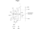
- FIG. FIG. 2 is a cross-sectional view of the magnetic core 1 viewed in a fourth direction DIR4.
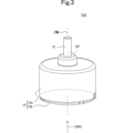
- FIG. 3 is a perspective view showing the appearance of a brushless motor 100 in which the magnetic core 1 is used.
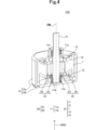
- FIG. 4 is an exploded perspective schematic view of a brushless motor 100 in which the magnetic core 1 is used.
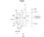
- FIG. 5 is a cross-sectional view of a magnetic core 6 according to a comparative example viewed in a fourth direction DIR4.
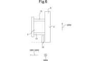
- FIG. 6 is a cross-sectional view of a magnetic core 6 around which a coil 13 is wound and a connecting member 15 according to a comparative example, viewed in a fourth direction DIR4.
- FIG. 7 is a cross-sectional view of the magnetic core 1 around which the coil 13 is wound and the connecting member 15, as viewed in the fourth direction DIR4.
- FIG. 8 is a perspective view of the magnetic core 1a.
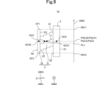
- FIG. 9 is a cross-sectional view of the magnetic core 1a viewed in the fourth direction DIR4.
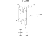
- FIG. 10 is an example of a cross-sectional view of the magnetic core 1 around which the coil 13 is wound, the connection member 15, and the wiring member 16 as viewed in the fourth direction DIR4.
- Fig. 1 is a perspective view of the magnetic core 1.
- Fig. 2 is a cross-sectional view of the magnetic core 1 as viewed in a fourth direction DIR4.
- the direction in which the teeth main body portion 31 extends is defined as the first direction DIR1.
- the direction along the rotation axis of the brushless motor 100 when the magnetic core 1 is assembled into the brushless motor 100 is defined as the second direction DIR2.
- the orthogonal projection of the first direction DIR1 onto a plane perpendicular to the second direction DIR2 is defined as the third direction DIR3.
- the third direction DIR3 is different from the first direction DIR1.
- the direction perpendicular to the second direction DIR2 and the third direction DIR3 is defined as the fourth direction DIR4.
- the first direction DIR1, the second direction DIR2, the third direction DIR3, and the fourth direction DIR4 are directions defined for the purpose of explanation.
- the first direction DIR1, the second direction DIR2, the third direction DIR3, and the fourth direction DIR4 during actual use of the magnetic core 1 do not necessarily have to coincide with the first direction DIR1, the second direction DIR2, the third direction DIR3, and the fourth direction DIR4 in this embodiment.
- the magnetic core 1 is used in a brushless motor 100.
- the brushless motor 100 is an example of a "rotating electric machine" according to the present invention.
- the magnetic core 1 has a core back portion 2 and teeth portion 3.
- the magnetic core 1 is a soft magnetic material. When a magnetic field is applied from the outside, the soft magnetic material is magnetized. When the application of the magnetic field is then stopped, the soft magnetic material loses its magnetization.
- An example of the material of such a soft magnetic material is iron.
- the magnetic core 1 is a molded body formed from soft magnetic powder. That is, each of the core back portion 2 and the teeth portion 3 is a molded body formed from soft magnetic powder.
- the material of the soft magnetic powder includes, for example, iron and a binder.
- the binder is, for example, a resin.
- the soft magnetic powder is, for example, a mixture of iron powder and epoxy resin, which is an example of a binder.
- Such a magnetic core 1 is produced, for example, by press molding. Furthermore, the outer surface of the magnetic core 1 is subjected to an insulating treatment.
- the core back portion 2 has a first main surface S1 and a second main surface S2 aligned in the third direction DIR3.
- the second main surface S2 is located in the third direction DIR3 further than the first main surface S1.
- each of the first main surface S1 and the second main surface S2 has a rectangular shape when viewed in the third direction DIR3.
- the core back portion 2 has a geometric center GC2.
- the geometric center GC2 is the position of the arithmetic mean taken over all points belonging to the core back portion 2.
- the core back portion 2 has a shape that is plane-symmetrical with respect to a plane perpendicular to the second direction DIR2.
- the teeth portion 3 includes a teeth main body portion 31 and a teeth tip portion 32.
- the teeth portion 3 has a geometric center GC3.
- the geometric center GC3 is the position of the arithmetic mean taken over all points belonging to the teeth portion 3.
- the teeth main body portion 31 extends from the core back portion 2 in the first direction DIR1. More specifically, the teeth main body portion 31 extends from the second main surface S2 in the first direction DIR1. The first direction DIR1 is not perpendicular to the second direction DIR2. Therefore, the third direction DIR3 is different from the first direction DIR1.
- the teeth main body portion 31 is in the shape of a quadrangular prism.
- the teeth main body portion 31 has a geometric center GC31.
- the geometric center GC31 is the position of the arithmetic mean taken over all points belonging to the teeth main body portion 31.
- the teeth main body portion 31 has a first end E1 and a second end E2, which are both ends in the second direction DIR2.
- the first end E1 is located further in the second direction DIR2 than the second end E2.
- the teeth main body portion 31 has a geometric center GC31, as shown in FIG. 2.
- the position PGC31 of the geometric center GC31 of the teeth main body portion 31 in the second direction DIR2 is equal to the position PGC31 of the geometric center GC31 of the core back portion 2.
- the second direction DIR2 is a direction along the rotation axis of the brushless motor 100 when the magnetic core 1 is assembled in the brushless motor 100, as shown in FIGS. 3 and 4.
- the tooth tip portion 32 has a third main surface S3 and a fourth main surface S4 aligned in the third direction DIR3.
- the fourth main surface S4 is located in the third direction DIR3 from the third main surface S3.
- each of the third main surface S3 and the fourth main surface S4 has a rectangular shape when viewed in the third direction DIR3.
- the tooth tip portion 32 has a geometric center GC32.
- the geometric center GC32 is the position of the arithmetic mean taken over all points belonging to the tooth tip portion 32.
- the position PGC2 of the geometric center GC32 of the tooth tip portion 32 in the second direction DIR2 is equal to the position PGC2 of the geometric center GC2 of the core back portion 2.
- the tooth tip portion 32 has a shape that is plane-symmetrical with respect to a plane perpendicular to the second direction DIR2.
- the tooth tip portion 32 has a first end face EF1 facing the second direction DIR2, and a second end face EF2 facing the opposite direction to the second direction DIR2.
- the first end face EF1 is located further in the second direction DIR2 than the second end face EF2.
- Such a tooth tip portion 32 is provided at the tip of the tooth main body portion 31 in the first direction DIR1, as shown in FIG. 1.
- the outer edge O2 of the core back portion 2 as viewed in the third direction DIR3 surrounds the outer edge O31 of the tooth main body portion 31 as viewed in the third direction DIR3, as shown in FIG. 1.
- the outer edge O32 of the tooth tip portion 32 as viewed in the third direction DIR3 surrounds the outer edge O31 of the tooth main body portion 31 as viewed in the third direction DIR3.
- the length of the tooth main body portion 31 in the second direction DIR2 is uniform in the third direction DIR3, as shown in FIG. 2.
- the position PGC3 of the geometric center GC3 of the teeth portion 3 is equal to the position PGC2 of the geometric center GC2 of the core back portion 2, as shown in FIG. 2.
- the line connecting the geometric centers of the cross sections of the teeth main body 31 perpendicular to the third direction DIR3 is defined as the first line L1.
- the geometric center of the cross section of the teeth main body 31 perpendicular to the third direction DIR3 is the position of the arithmetic mean taken over all points belonging to the cross section of the teeth main body 31 perpendicular to the third direction DIR3.
- the first line L1 is a straight line as shown in FIG. 2.
- the position of the first line L1 at the tip of the teeth main body 31 in the first direction DIR1 and the position of the first line L1 at the end of the teeth main body 31 opposite to the tip are shifted in the second direction DIR2.
- the first line L1 at the tip of the teeth main body 31 in the first direction DIR1 is located in the opposite direction of the second direction DIR2 from the first line L1 at the end of the teeth main body 31 opposite to the tip of the teeth main body 31 in the first direction DIR1.
- Fig. 3 is an external perspective view of the brushless motor 100 using a magnetic core 1.
- Fig. 4 is an exploded perspective schematic view of the brushless motor 100 using a magnetic core 1. Note that in Fig. 4, reference symbols are given only to representative magnetic cores 1, coils 13, and insulating members 14 among the multiple magnetic cores 1, multiple coils 13, and multiple insulating members 14.
- the brushless motor 100 includes a rotor 20 and a stator assembly 10. As shown in FIG. 4, the stator assembly 10 is disposed around the rotor 20 when viewed in the second direction DIR2. In other words, the brushless motor 100 is an inner rotor type.
- the rotor 20 includes a shaft 21 and a rotor member 22.
- the shaft 21 has a shape that extends in the second direction DIR2. More specifically, the shaft 21 is cylindrical.
- the rotor member 22 is cylindrical.
- the central axes of the shaft 21 and the rotor member 22 are the Z-axis. In other words, the rotation axis of the brushless motor 100 is the Z-axis. Therefore, the second direction DIR2 is a direction along the Z-axis.
- the rotor member 22 includes a soft magnetic body 23 and a hard magnetic body 24.
- the rotor member 22 is attached to the outer peripheral surface of the shaft 21 in the radial direction centered on the Z axis. More specifically, the soft magnetic body 23 is attached to the outer peripheral surface of the shaft 21 in the radial direction centered on the Z axis.
- the hard magnetic body 24 is attached to the outer peripheral surface of the soft magnetic body 23 in the radial direction centered on the Z axis.
- the rotor member 22 is arranged so that the position PGC22 in the second direction DIR2 of the geometric center GC22 of the rotor member 22 is equal to the position PGC2 in the second direction DIR2 of the geometric center GC2 of the core back portion 2.
- the geometric center GC22 is the position of the arithmetic mean taken over all points belonging to the rotor member 22.
- the soft magnetic body 23 is a soft magnetic body.
- the hard magnetic body 24 is a hard magnetic body. When a magnetic field is applied from the outside, the hard magnetic body is magnetized. Even if the application of the magnetic field is then stopped, the hard magnetic body does not lose its magnetization. Such hard magnetic material is a magnet.
- the stator assembly 10 includes a bearing 11, a housing 12, a plurality of magnetic cores 1, a plurality of coils 13, a plurality of insulating members 14, and a connecting member 15.
- the brushless motor 100 includes a magnetic core 1.
- the bearing 11 supports the shaft 21 so that it can rotate in the circumferential direction around the Z-axis. More specifically, as shown in FIG. 4, the bearing 11 has a first bearing 11a and a second bearing 11b. Each of the first bearing 11a and the second bearing 11b is, for example, a ball bearing. Each of the first bearing 11a and the second bearing 11b is cylindrical. The central axis of each of the first bearing 11a and the second bearing 11b is the Z-axis. In other words, the central axis of each of the first bearing 11a and the second bearing 11b coincides with the central axis of the shaft 21.
- the first bearing 11a is positioned further in the second direction DIR2 than the second bearing 11b.
- the first bearing 11a is also positioned further in the second direction DIR2 than the rotor member 22.
- the second bearing 11b is positioned in the opposite direction of the second direction DIR2 than the rotor member 22.
- the second bearing 11b supports the end of the shaft 21 that is positioned opposite the second direction DIR2.
- the housing 12 has a first housing 12a and a second housing 12b.
- the first housing 12a is cylindrical.
- the central axis of the first housing 12a is the Z axis.
- the first housing 12a is positioned further in the second direction DIR2 than the second housing 12b.
- the first housing 12a also has an opening OP.
- the end of the shaft 21 in the second direction DIR2 protrudes from the opening OP in the second direction DIR2.
- the brushless motor 100 is a single-shaft type.
- the first housing 12a supports the first bearing 11a, the multiple magnetic cores 1, the multiple coils 13, and the multiple insulating members 14.
- the second housing 12b supports the second bearing 11b.
- the materials of the first housing 12a and the second housing 12b are, for example, a highly rigid material such as SUS.
- the number of magnetic cores 1, the number of coils 13, and the number of insulating members 14 is nine. Each of the nine coils 13 and each of the nine insulating members 14 is provided corresponding to each of the nine magnetic cores 1. More specifically, if a set including one magnetic core 1, one coil 13, and one insulating member 14 is considered to be one set, the nine sets are lined up in the circumferential direction centered on the Z axis. Each set is disposed around the hard magnetic material 24 with a gap therebetween. Note that each set has the same structure. Therefore, one set including one magnetic core 1, one coil 13, and one insulating member 14 will be described.
- the magnetic core 1 is magnetized by both the magnetic field generated by the hard magnetic material 24 and the magnetic field generated by the coil 13. As a result, the magnetic core 1 generates a magnetic force that rotates the rotor. Note that, as shown in FIG. 4, there is an air gap between the magnetic core 1 and the rotor member 22.
- the first direction DIR1 is the direction toward the rotation axis of the brushless motor 100 when the magnetic core 1 is incorporated into the brushless motor 100.
- the coil 13 is wound around the teeth main body 31 so as to be positioned around the magnetic core 1 when viewed in the radial direction centered on the Z-axis.
- the coil 13 is made of a conductive material such as copper.
- the coil 13 has a structure in which the surface of the copper wire is covered with an insulating film. The coil 13 generates a magnetic field when a current flows through the coil 13.
- the insulating member 14 is an insulator. As shown in FIG. 4, the insulating member 14 is disposed between the magnetic core 1 and the coil 13. This electrically insulates the magnetic core 1 and the coil 13. In this embodiment, the insulating member 14 is in the form of a film, but it may also be in the form of a plate. The insulating member 14 may also be disposed so that a portion of the insulating member 14 is disposed between the magnetic core 1 and the coil 13. Thus, the insulating member 14 may be disposed over the entire surface of the coil 13.
- the connecting member 15 is electrically connected to the coil 13.
- the connecting member 15 is, for example, a substrate.
- the substrate includes a substrate body (not shown) and a plurality of mounting electrodes (not shown) provided on the surface of the substrate body.
- the substrate body is a glass epoxy substrate.
- the plurality of mounting electrodes are copper electrodes.
- the coil 13 is electrically connected to each of the plurality of mounting electrodes.
- a current is supplied to the coil 13 from a power source (not shown).
- the rotation of the rotor 20 is controlled by controlling this current.
- Fig. 5 is a cross-sectional view of the magnetic core 6 according to the comparative example, viewed in the fourth direction DIR4.
- Fig. 6 is a cross-sectional view of the magnetic core 6 and the connecting member 15 according to the comparative example, around which the coil 13 is wound, viewed in the fourth direction DIR4.
- Fig. 7 is a cross-sectional view of the magnetic core 1 and the connecting member 15 around which the coil 13 is wound, viewed in the fourth direction DIR4. Note that the number of turns of the coil 13 is equal in Figs. 6 and 7.
- the magnetic core 6 according to the comparative example will be described. Note that, for the magnetic core 6 according to the comparative example, only the parts that are different from the magnetic core 1 will be described, and the rest will be omitted.
- the third direction DIR3 is equal to the first direction DIR1, as shown in FIG. 5. Therefore, in the magnetic core 6 according to the comparative example, the position of the first line L1 in the second direction DIR2 at the tip of the tooth main body 31 in the first direction DIR1 is equal to the position of the first line L1 in the second direction DIR2 at the end of the tooth main body 31 opposite the tip. In other words, the position of the first line L1 at the tip of the tooth main body 31 in the first direction DIR1 and the position of the first line L1 at the end of the tooth main body 31 opposite the tip are not shifted in the second direction DIR2.
- the coil 13 is wound around the teeth main body 31 as shown in FIG. 6.
- the connecting member 15 is disposed in a region that overlaps with the teeth portion 3 when viewed in the second direction DIR2 and is located in the opposite direction of the second direction DIR2 from the teeth portion 3, the end of the connecting member 15 in the opposite direction of the second direction DIR2 may be located in the opposite direction of the second direction DIR2 than the end of the core back portion 2 in the opposite direction of the second direction DIR2. This increases the length of the brushless motor 100 in the second direction DIR2.
- the position of the first line L1 at the tip of the tooth main body portion 31 in the first direction DIR1 and the position of the first line L1 at the end of the tooth main body portion 31 opposite the tip are shifted in the second direction DIR2. More specifically, the first line L1 at the tip of the tooth main body portion 31 in the first direction DIR1 is located in the opposite direction of the second direction DIR2 from the first line L1 at the end of the tooth main body portion 31 opposite the tip of the tooth main body portion 31 in the first direction DIR1. As a result, the coil 13 according to the first embodiment of the present invention is located further in the second direction DIR2 than the coil 13 according to the comparative example, as shown in FIG. 7.
- the connecting member 15 is disposed in a region that overlaps with the teeth portion 3 when viewed in the second direction DIR2 and is located in the opposite direction of the second direction DIR2 from the teeth portion 3, the end of the connecting member 15 in the opposite direction of the second direction DIR2 can be positioned in the second direction DIR2 further than the end of the core back portion 2 in the opposite direction of the second direction DIR2.
- the connecting member 15 is located on the core back portion 2 side between the tooth tip portion 32 and the core back portion 2, and in the opposite direction of the second direction DIR2 from the tooth main body portion 31.
- the length in the second direction DIR2 of the brushless motor 100 according to the first embodiment of the present invention can be made shorter than the length in the second direction DIR2 of the brushless motor 100 according to the comparative example. Therefore, the magnetic core 1 allows the brushless motor 100 to be made low-profile and small-sized.
- the magnetic core 1 makes it easier to form the magnetic core 1. More specifically, the core back portion 2 and the teeth tip portion 32 each have a shape that is plane-symmetrical with respect to a plane perpendicular to the second direction DIR2. Therefore, for example, when manufacturing the magnetic core 1 by press molding, the magnetic core 1 can be manufactured using a die that has a shape that is plane-symmetrical with respect to a plane perpendicular to the second direction DIR2, and a punch that has a shape that is plane-symmetrical with respect to a plane perpendicular to the second direction DIR2. As a result, the magnetic core 1 makes it easier to form the magnetic core 1.
- Fig. 8 is a perspective view of the magnetic core 1a.
- Fig. 9 is a cross-sectional view of the magnetic core 1a viewed in the fourth direction DIR4. Note that, for the magnetic core 1a according to the first modified example, only the parts different from the magnetic core 1 according to the first embodiment will be described, and the rest will be omitted.
- magnetic core 1a differs from magnetic core 1 in that first line L1 is a broken line.
- the magnetic core 1a described above has the same effect as the magnetic core 1.
- FIG. 10 is an example of a cross-sectional view of the magnetic core 1 around which the coil 13 is wound and the wiring member 16 as viewed in the fourth direction DIR4. Note that, regarding the stator assembly 10a according to the second embodiment, only the parts that are different from the stator assembly 10 according to the first embodiment will be described, and the rest will be omitted.
- the stator assembly 10a differs from the stator assembly 10 in that it further includes a wiring member 16.
- the wiring member 16 is, for example, a bus bar.
- the wiring member 16 is disposed in a region that overlaps with the teeth portion 3 when viewed in the second direction DIR2 and is located further in the second direction DIR2 than the teeth portion 3.
- the end of the wiring member 16 in the second direction DIR2 can be positioned in the opposite direction of the second direction DIR2 than the end of the core back portion 2 in the second direction DIR2.
- the wiring member 16 is positioned on the tooth tip portion 32 side between the tooth tip portion 32 and the core back portion 2, and further in the second direction DIR2 than the tooth main body portion 31.
- the length of the brushless motor 100 in the second direction DIR2 can be made shorter than the length of the brushless motor 100 in the second direction DIR2 according to the comparative example. Therefore, according to the stator assembly 10a, the brushless motor 100 can be made lower in height and smaller.
- the connecting member 15 may be located on the tooth tip 32 side between the tooth tip 32 and the core back portion 2, and further in the second direction DIR2 than the tooth main body portion 31, and the wiring member 16 may be located on the core back portion 2 side between the tooth tip 32 and the core back portion 2, and further in the opposite direction of the second direction DIR2 than the tooth main body portion 31. Even in this case, the brushless motor 100 can be made low-profile and small-sized.
- the magnetic core according to the present invention is not limited to the magnetic cores 1 and 1a, and may be modified within the scope of the present invention.
- the structures of the magnetic cores 1 and 1a may be combined in any desired manner.
- stator assembly according to the present invention is not limited to stator assemblies 10 and 10a, and can be modified within the scope of the gist of the invention.
- the structures of stator assemblies 10 and 10a may be combined in any manner.
- the rotating electric machine may have a structure in which the rotor is rotated by electricity, or a structure in which electricity is generated by the rotation of the rotor.
- the rotating electric machine may have at least one of the magnetic cores 1 and 1a, and may also have brushes.
- the magnetic cores 1 and 1a may be made by laminating electromagnetic steel sheets.
- the magnetic cores 1 and 1a may be made of any soft magnetic material.
- the outer surface of the magnetic cores 1, 1a does not need to be insulated.
- each of the first main surface S1 and the second main surface S2 of the core back portion 2 does not have to have a rectangular shape when viewed in the third direction DIR3.
- the core back portion 2 does not have to have a shape that is plane-symmetrical with respect to a plane perpendicular to the second direction DIR2.
- the tooth body portion 31 does not have to be rectangular prism shaped.
- the position PGC31 of the geometric center GC31 of the tooth main body portion 31 in the second direction DIR2 may be different from the position PGC31 of the geometric center GC31 of the core back portion 2.
- each of the third principal surface S3 and the fourth principal surface S4 of the tooth tip portion 32 does not have to have a rectangular shape when viewed in the third direction DIR3.
- the position PGC2 of the geometric center GC32 of the tooth tip portion 32 in the second direction DIR2 may be different from the position PGC2 of the geometric center GC2 of the core back portion 2.
- the tooth tip portion 32 does not have to have a shape that is plane-symmetrical with respect to a plane perpendicular to the second direction DIR2.
- the position PGC2 of the geometric center GC32 of the tooth tip portion 32 in the second direction DIR2 may be different from the position PGC2 of the geometric center GC2 of the core back portion 2.
- the outer edge O2 of the core back portion 2 as viewed in the third direction DIR3 does not have to surround the outer edge O31 of the tooth main body portion 31 as viewed in the third direction DIR3. Furthermore, the outer edge O32 of the tooth tip portion 32 as viewed in the third direction DIR3 does not have to surround the outer edge O31 of the tooth main body portion 31 as viewed in the third direction DIR3.
- the length of the tooth body portion 31 in the second direction DIR2 does not have to be uniform in the third direction DIR3.
- first line L1 is not limited to being a straight line or a broken line, and may be a curved line. Furthermore, the first line L1 may include a straight line or a curved line.
- the first line L1 at the tip of the tooth body 31 in the first direction DIR1 may be located in the second direction DIR2 further than the first line L1 at the end of the tooth body 31 opposite the tip of the tooth body 31 in the first direction DIR1.
- the connecting member 15 is arranged in a region that overlaps with the tooth portion 3 as viewed in the second direction DIR2 and is located in the opposite direction of the second direction DIR2 from the tooth portion 3, the end of the connecting member 15 in the opposite direction of the second direction DIR2 can be located in the second direction DIR2 further than the end of the core back portion 2 in the opposite direction of the second direction DIR2.
- the length of the brushless motor 100 in the second direction DIR2 can be made shorter than the length of the brushless motor 100 in the second direction DIR2 according to the comparative example. As a result, the brushless motor 100 can be made smaller.
- the brushless motor 100 may be an outer rotor type.
- the first direction DIR1 is the opposite direction to the direction toward the rotation shaft of the brushless motor 100 when the magnetic core 1 is assembled in the brushless motor 100.
- the brushless motor 100 is not limited to a single-shaft type.
- the brushless motor 100 may be, for example, a double-shaft type.
- first bearing 11a and the second bearing 11b are not limited to ball bearings.
- the materials for the first housing 12a and the second housing 12b may be any material that has high rigidity.
- each of the magnetic cores 1, the coils 13, and the insulating members 14 is not limited to nine. Each of the coils 13 and each of the insulating members 14 may be provided in correspondence with each of the magnetic cores 1.
- connecting member 15 is not limited to a substrate.
- the connecting member 15 may be, for example, a terminal block.
- the connecting member 15 is not a required component of the stator assembly 10a.
- the wiring member 16 is not limited to a bus bar.
- the wiring member 16 may be, for example, a cable.
- the present invention has the following configuration.
- a magnetic core for use in a rotating electrical machine comprising: A core back portion; a teeth portion including a teeth main body portion extending in a first direction from the core back portion and a teeth tip portion provided at a tip of the teeth main body portion in the first direction; Equipped with a position of a geometric center of the teeth portion is equal to a position of a geometric center of the core back portion in a second direction that is a direction along a rotation axis of the rotating electric machine when the magnetic core is assembled in the rotating electric machine; An orthogonal projection of the first direction onto a plane perpendicular to the second direction is defined as a third direction; A line connecting geometric centers of cross sections of the teeth main body portions perpendicular to the third direction is defined as a first line, a position of the first line at the tip of the tooth main body portion and a position of the first line at an end of the tooth main body portion opposite to the tip are shifted in the second direction.
- Magnetic core Magnetic core.
- the first line is a straight line.
- the first line is a broken line.
- the core back portion has a shape that is plane-symmetrical with respect to a plane perpendicular to the second direction
- the tip end portion of the teeth has a shape that is plane-symmetrical with respect to a plane perpendicular to the second direction.
- a magnetic core according to any one of (1) to (3).
- the length of the tooth main body portion in the second direction is uniform in the third direction.
- Each of the core back portion and the teeth portion is a molded body formed from soft magnetic powder.
- the material of the soft magnetic powder includes iron and resin; A magnetic core according to (6).
- a magnetic core according to any one of (1) to (7) is provided. Rotating electrical machines.
- a magnetic core according to any one of (1) to (7) is provided. Brushless motor.
Landscapes
- Engineering & Computer Science (AREA)
- Power Engineering (AREA)
- Iron Core Of Rotating Electric Machines (AREA)
Priority Applications (4)
| Application Number | Priority Date | Filing Date | Title |
|---|---|---|---|
| CN202380061974.8A CN119768994A (zh) | 2022-12-05 | 2023-11-28 | 磁芯、定子组件、旋转电气机械和无刷马达 |
| JP2024562705A JP7852742B2 (ja) | 2022-12-05 | 2023-11-28 | 磁性体コア、ステータアッシー、回転電気機械及びブラシレスモータ |
| DE112023002747.1T DE112023002747T5 (de) | 2022-12-05 | 2023-11-28 | Magnetkern, statoreinheit, drehende elektrische maschine, und bürstenloser motor |
| US19/082,432 US20250219479A1 (en) | 2022-12-05 | 2025-03-18 | Magnetic core, stator assembly, rotating electrical machine, and brushless motor |
Applications Claiming Priority (2)
| Application Number | Priority Date | Filing Date | Title |
|---|---|---|---|
| JP2022194081 | 2022-12-05 | ||
| JP2022-194081 | 2022-12-05 |
Related Child Applications (1)
| Application Number | Title | Priority Date | Filing Date |
|---|---|---|---|
| US19/082,432 Continuation US20250219479A1 (en) | 2022-12-05 | 2025-03-18 | Magnetic core, stator assembly, rotating electrical machine, and brushless motor |
Publications (1)
| Publication Number | Publication Date |
|---|---|
| WO2024122405A1 true WO2024122405A1 (ja) | 2024-06-13 |
Family
ID=91379302
Family Applications (1)
| Application Number | Title | Priority Date | Filing Date |
|---|---|---|---|
| PCT/JP2023/042583 Ceased WO2024122405A1 (ja) | 2022-12-05 | 2023-11-28 | 磁性体コア、ステータアッシー、回転電気機械及びブラシレスモータ |
Country Status (5)
| Country | Link |
|---|---|
| US (1) | US20250219479A1 (cg-RX-API-DMAC7.html) |
| JP (1) | JP7852742B2 (cg-RX-API-DMAC7.html) |
| CN (1) | CN119768994A (cg-RX-API-DMAC7.html) |
| DE (1) | DE112023002747T5 (cg-RX-API-DMAC7.html) |
| WO (1) | WO2024122405A1 (cg-RX-API-DMAC7.html) |
Citations (4)
| Publication number | Priority date | Publication date | Assignee | Title |
|---|---|---|---|---|
| JP2000201458A (ja) * | 1998-06-30 | 2000-07-18 | Mitsubishi Electric Corp | 鉄心装置及びその製造方法 |
| JP2008061407A (ja) * | 2006-08-31 | 2008-03-13 | Jtekt Corp | 電動モータ |
| JP2010166810A (ja) * | 2010-03-26 | 2010-07-29 | Mitsubishi Electric Corp | 回転電機の固定子 |
| JP2017060395A (ja) * | 2015-09-16 | 2017-03-23 | ヤマハ発動機株式会社 | 回転電機及びステータ |
-
2023
- 2023-11-28 JP JP2024562705A patent/JP7852742B2/ja active Active
- 2023-11-28 DE DE112023002747.1T patent/DE112023002747T5/de active Pending
- 2023-11-28 WO PCT/JP2023/042583 patent/WO2024122405A1/ja not_active Ceased
- 2023-11-28 CN CN202380061974.8A patent/CN119768994A/zh active Pending
-
2025
- 2025-03-18 US US19/082,432 patent/US20250219479A1/en active Pending
Patent Citations (4)
| Publication number | Priority date | Publication date | Assignee | Title |
|---|---|---|---|---|
| JP2000201458A (ja) * | 1998-06-30 | 2000-07-18 | Mitsubishi Electric Corp | 鉄心装置及びその製造方法 |
| JP2008061407A (ja) * | 2006-08-31 | 2008-03-13 | Jtekt Corp | 電動モータ |
| JP2010166810A (ja) * | 2010-03-26 | 2010-07-29 | Mitsubishi Electric Corp | 回転電機の固定子 |
| JP2017060395A (ja) * | 2015-09-16 | 2017-03-23 | ヤマハ発動機株式会社 | 回転電機及びステータ |
Also Published As
| Publication number | Publication date |
|---|---|
| JPWO2024122405A1 (cg-RX-API-DMAC7.html) | 2024-06-13 |
| US20250219479A1 (en) | 2025-07-03 |
| DE112023002747T5 (de) | 2025-04-10 |
| JP7852742B2 (ja) | 2026-04-28 |
| CN119768994A (zh) | 2025-04-04 |
Similar Documents
| Publication | Publication Date | Title |
|---|---|---|
| US7508109B2 (en) | Commutator motor | |
| US20020093260A1 (en) | Axial directional gap type eccentric rotor having stop position maintaining unit and flat coreless vibration motor using the rotor | |
| US20250219477A1 (en) | Magnetic core, coil-equipped magnetic core, and rotary electric machine | |
| JP2004222356A (ja) | 回転電気機器 | |
| JP7852742B2 (ja) | 磁性体コア、ステータアッシー、回転電気機械及びブラシレスモータ | |
| CN113924712B (zh) | 旋转电机及制造定子核心的方法 | |
| JPWO2024122405A5 (cg-RX-API-DMAC7.html) | ||
| JP2018160956A (ja) | ブラシレスモータ | |
| WO2024122406A1 (ja) | 磁性体コア、回転電気機械及びブラシレスモータ | |
| WO2023189285A1 (ja) | 回転子及び電動機 | |
| WO2024122407A1 (ja) | 磁性体コア及び回転電気機械 | |
| JP7848933B2 (ja) | ステータ部材、回転電気機械及びステータ部材の製造方法 | |
| EP4156460A1 (en) | Rotary electric machine | |
| US20250219476A1 (en) | Rotating electric machine | |
| JP2024121489A (ja) | ステータ及び回転電気機械 | |
| CN118020232A (zh) | 转子及旋转电机 | |
| WO2024181096A1 (ja) | ステータ及び回転電気機械 | |
| WO2024122408A1 (ja) | 磁性体コア、コイル付き磁性体コア、回転電気機械及びブラシレスモータ | |
| JP2018207617A (ja) | モータ | |
| US20240186844A1 (en) | Magnetic core, winding with magnetic core, rotary electric machine, and brushless motor | |
| EP4535615A1 (en) | Electric motor, core block, and stator core | |
| US20260039164A1 (en) | Coil body, armature and rotary electric machine | |
| JP2024131471A (ja) | ステータ、モータ、および送風機 | |
| JP5230303B2 (ja) | ステッピングモータ | |
| WO2023188524A1 (ja) | 磁性体コア、磁性体コア付き巻線、回転電気機械及びブラシレスモータ |
Legal Events
| Date | Code | Title | Description |
|---|---|---|---|
| 121 | Ep: the epo has been informed by wipo that ep was designated in this application |
Ref document number: 23900521 Country of ref document: EP Kind code of ref document: A1 |
|
| WWE | Wipo information: entry into national phase |
Ref document number: 112023002747 Country of ref document: DE |
|
| WWE | Wipo information: entry into national phase |
Ref document number: 2024562705 Country of ref document: JP |
|
| WWE | Wipo information: entry into national phase |
Ref document number: 202380061974.8 Country of ref document: CN |
|
| WWP | Wipo information: published in national office |
Ref document number: 202380061974.8 Country of ref document: CN |
|
| WWP | Wipo information: published in national office |
Ref document number: 112023002747 Country of ref document: DE |
|
| 122 | Ep: pct application non-entry in european phase |
Ref document number: 23900521 Country of ref document: EP Kind code of ref document: A1 |