WO2024122265A1 - コネクタ付き光ファイバケーブルおよび光伝送システム - Google Patents
コネクタ付き光ファイバケーブルおよび光伝送システム Download PDFInfo
- Publication number
- WO2024122265A1 WO2024122265A1 PCT/JP2023/040406 JP2023040406W WO2024122265A1 WO 2024122265 A1 WO2024122265 A1 WO 2024122265A1 JP 2023040406 W JP2023040406 W JP 2023040406W WO 2024122265 A1 WO2024122265 A1 WO 2024122265A1
- Authority
- WO
- WIPO (PCT)
- Prior art keywords
- core
- optical
- optical connector
- optical fiber
- connector
- Prior art date
- Legal status (The legal status is an assumption and is not a legal conclusion. Google has not performed a legal analysis and makes no representation as to the accuracy of the status listed.)
- Ceased
Links
Images


Classifications
-
- G—PHYSICS
- G02—OPTICS
- G02B—OPTICAL ELEMENTS, SYSTEMS OR APPARATUS
- G02B6/00—Light guides; Structural details of arrangements comprising light guides and other optical elements, e.g. couplings
- G02B6/02—Optical fibres with cladding with or without a coating
- G02B6/02042—Multicore optical fibres
-
- G—PHYSICS
- G02—OPTICS
- G02B—OPTICAL ELEMENTS, SYSTEMS OR APPARATUS
- G02B6/00—Light guides; Structural details of arrangements comprising light guides and other optical elements, e.g. couplings
- G02B6/24—Coupling light guides
- G02B6/36—Mechanical coupling means
- G02B6/38—Mechanical coupling means having fibre to fibre mating means
- G02B6/3807—Dismountable connectors, i.e. comprising plugs
- G02B6/389—Dismountable connectors, i.e. comprising plugs characterised by the method of fastening connecting plugs and sockets, e.g. screw- or nut-lock, snap-in, bayonet type
- G02B6/3893—Push-pull type, e.g. snap-in, push-on
Definitions
- This disclosure relates to a connectorized optical fiber cable and an optical transmission system.
- This application claims priority to Japanese Application No. 2022-196942, filed on December 9, 2022, and incorporates by reference all of the contents of said Japanese application.
- Patent documents 1 and 2 disclose optical fiber cables with connectors that have multi-core optical fibers.
- a connectorized optical fiber cable includes a multi-core optical fiber having a first core to an Nth core (N is an integer of 2 or more), a first optical connector attached to a first end of the multi-core optical fiber, and a second optical connector attached to a second end of the multi-core optical fiber.
- the arrangement of the first core to the Nth core is rotationally asymmetric around the central axis in a cross section of the multi-core optical fiber perpendicular to the central axis of the multi-core optical fiber.
- the first optical connector and the second optical connector are optical connectors of a type that are connected to the counterpart optical connector in a state where the connectors face upwards in the same direction.
- the arrangement of the end faces from the first core to the Nth core at the connection end face of the second optical connector is an arrangement that is the inversion of the arrangement of the end faces from the first core to the Nth core at the connection end face of the first optical connector with respect to the central axis of the connection end face along the direction in which the optical connectors face upwards.
- FIG. 1A is a perspective view for explaining the types of optical connectors.
- FIG. 1B is a perspective view for explaining the types of optical connectors.
- FIG. 2 is a perspective view showing how a plurality of optical fiber cables with connectors are connected to each other.
- FIG. 3A is a diagram illustrating an example of a cross section perpendicular to the central axis of a multi-core optical fiber included in an optical fiber cable.
- FIG. 3B is a diagram illustrating an example of a cross section perpendicular to the central axis of a multi-core optical fiber included in an optical fiber cable.
- FIG. 4A is a diagram illustrating another example of a cross section perpendicular to the central axis of a multi-core optical fiber included in an optical fiber cable.
- FIG. 4B is a diagram illustrating another example of a cross section perpendicular to the central axis of a multi-core optical fiber included in an optical fiber cable.
- FIG. 5 is a diagram showing the core arrangement when the connection end faces of the first optical connector and the second optical connector in one optical fiber cable with connectors are viewed from the front.
- FIG. 6 is a diagram showing the correspondence between the cores.
- FIG. 7A is a perspective view showing the appearance of the MPO connector.
- FIG. 7B is a perspective view showing the appearance of an MT ferrule provided in the MPO connector.
- FIG. 8A is a front view of the connection end face of an MT ferrule.
- FIG. 8B is a side view of the MT ferrule.
- FIG. 8C is a side view of the MT ferrule.
- FIG. 9A is a side view showing a state in which the connection end faces of two MT ferrules face each other.
- FIG. 9B is a side view showing the connection end faces of two MT ferrules facing each other.
- Fig. 10 is a diagram showing the core arrangement of each optical fiber when the connection end faces of the first optical connector and the second optical connector in one connectorized optical fiber cable are viewed from the front when the first optical connector and the second optical connector are MPO connectors. Note that Fig. 10 shows the core arrangement of one representative optical fiber among the multiple optical fibers provided in the connectorized optical fiber cable, and the core arrangements of the other optical fibers are the same as that in Fig. 10.
- FIG. 10 shows the core arrangement of one representative optical fiber among the multiple optical fibers provided in the connectorized optical fiber cable, and the core arrangements of the other optical fibers are the same as that in Fig. 10.
- FIG. 11 is a diagram showing the correspondence between the cores.
- FIG. 12A is a diagram showing modified examples of the number and arrangement of cores.
- FIG. 12B is a diagram showing modified examples of the number and arrangement of cores.
- FIG. 12C is a diagram showing modified examples of the number and arrangement of cores.
- FIG. 12D is a diagram showing modified examples of the number and arrangement of cores.
- FIG. 13 is a diagram showing another embodiment of the core arrangement when the connection end faces of the first optical connector and the second optical connector in a single optical fiber cable with connectors are viewed from the front.
- FIG. 14A is a diagram for explaining the effect obtained by the core arrangement shown in FIG.
- FIG. 14B is a diagram for explaining the effect obtained by the core arrangement shown in FIG. FIG.
- FIG. 14C is a diagram for explaining the effect obtained by the core arrangement shown in FIG.
- FIG. 14D is a diagram for explaining the effect obtained by the core arrangement shown in FIG.
- FIG. 14E is a diagram for explaining the effect obtained by the core arrangement shown in FIG.
- FIG. 14F is a diagram for explaining the effect obtained by the core arrangement shown in FIG.
- FIG. 14G is a diagram for explaining the effect obtained by the core arrangement shown in FIG.
- FIG. 14H is a diagram for explaining the effect obtained by the core arrangement shown in FIG.
- FIG. 15A is a diagram for explaining the effect obtained by the core arrangement shown in FIG.
- FIG. 15B is a diagram for explaining the effect obtained by the core arrangement shown in FIG.
- FIG. 15C is a diagram for explaining the effect obtained by the core arrangement shown in FIG. FIG.
- FIG. 15D is a diagram for explaining the effect obtained by the core arrangement shown in FIG.
- FIG. 15E is a diagram for explaining the effect obtained by the core arrangement shown in FIG.
- FIG. 15F is a diagram for explaining the effect obtained by the core arrangement shown in FIG.
- FIG. 15G is a diagram for explaining the effect obtained by the core arrangement shown in FIG.
- FIG. 15H is a diagram for explaining the effect obtained by the core arrangement shown in FIG.
- FIG. 16A is a diagram showing modified examples of the number and arrangement of cores.
- FIG. 16B is a diagram showing modified examples of the number and arrangement of cores.
- FIG. 16C is a diagram showing modified examples of the number and arrangement of cores.
- FIG. 16D is a diagram showing modified examples of the number and arrangement of cores.
- FIG. 16A is a diagram showing modified examples of the number and arrangement of cores.
- FIG. 16B is a diagram showing modified examples of the number and arrangement of cores.
- FIG. 16C is a
- FIG 17 is a top view showing a schematic diagram of one SC connector and another SC connector to which the SC connector is connected, in which the connection end face of the ferrule of the SC connector is inclined laterally.
- Figure 18 is a diagram showing the core arrangement of the first optical connector and the second optical connector in a connectorized optical fiber cable when the first optical connector and the second optical connector are SC connectors as shown in Figure 17, when the connection end faces of the first optical connector and the second optical connector are viewed from the front.
- Figure 19A is a diagram to explain the core arrangement when the first optical connector and the second optical connector are of a type that are connected to the mating optical connector with their upwardly aligned orientations, and when the arrangement from the first core to the Nth core is rotationally asymmetric around the central axis.
- Figure 19B is a diagram to explain the core arrangement when the first optical connector and the second optical connector are of a type that are connected to the mating optical connector with their upward facing alignment, and when the arrangement from the first core to the Nth core is rotationally asymmetric around the central axis.
- Figure 20A is a diagram to explain the core arrangement when the first optical connector and the second optical connector are of a type that are connected to the mating optical connector in an inverted upward direction, and when the arrangement from the first core to the Nth core is rotationally asymmetric around the central axis.
- FIG. 20B is a diagram to explain the core arrangement when the first optical connector and the second optical connector are of a type that are connected to the mating optical connector in an inverted upward direction, and the arrangement from the first core to the Nth core is rotationally asymmetric around the central axis.
- FIG. 21A is a diagram for explaining the effect obtained by the core arrangement shown in FIG.
- FIG. 21B is a diagram for explaining the effect obtained by the core arrangement shown in FIG.
- FIG. 21C is a diagram for explaining the effect obtained by the core arrangement shown in FIG.
- FIG. 21D is a diagram for explaining the effect obtained by the core arrangement shown in FIG.
- FIG. 21E is a diagram for explaining the effect obtained by the core arrangement shown in FIG. FIG.
- FIG. 21F is a diagram for explaining the effect obtained by the core arrangement shown in FIG.
- FIG. 21G is a diagram for explaining the effect obtained by the core arrangement shown in FIG.
- FIG. 21H is a diagram for explaining the effect obtained by the core arrangement shown in FIG.
- FIG. 22A is a diagram for explaining the effect obtained by the core arrangement shown in FIG. 20.
- FIG. 22B is a diagram for explaining the effect obtained by the core arrangement shown in FIG. 20.
- FIG. 22C is a diagram for explaining the effect obtained by the core arrangement shown in FIG. 20.
- FIG. 22D is a diagram for explaining the effect obtained by the core arrangement shown in FIG. 20.
- FIG. 22E is a diagram for explaining the effect obtained by the core arrangement shown in FIG. 20.
- FIG. 22A is a diagram for explaining the effect obtained by the core arrangement shown in FIG. 20.
- FIG. 22B is a diagram for explaining the effect obtained by the core arrangement shown in FIG. 20.
- FIG. 22C is a diagram for explaining
- FIG. 22F is a diagram for explaining the effect obtained by the core arrangement shown in FIG.
- FIG. 22G is a diagram for explaining the effect obtained by the core arrangement shown in FIG. 20.
- FIG. 22H is a diagram for explaining the effect obtained by the core arrangement shown in FIG.
- FIG. 23 is a diagram showing a schematic diagram of an optical transmission system including two types of optical fiber cables with connectors as a first modified example.
- Figure 24A is a diagram showing an example of an optical connector of a type in which a first optical connector and a second optical connector are connected in an inverted upward direction relative to a mating optical connector, and the end faces of the first optical fiber to the Mth optical fiber are arranged in multiple rows at the connection end face.
- Figure 24B is a diagram showing an example of an optical connector of a type in which the first optical connector and the second optical connector are connected in an inverted upward direction relative to the mating optical connector, and the end faces of the first optical fiber to the Mth optical fiber are arranged in multiple rows at the connection end face.
- Figure 25A is a diagram showing an example of an optical connector of a type in which a first optical connector and a second optical connector are connected in an inverted upward direction relative to a mating optical connector, and the end faces of the first optical fiber to the Mth optical fiber are arranged in multiple rows at the connection end face.
- Figure 25B is a diagram showing an example of an optical connector of a type in which the first optical connector and the second optical connector are connected in an inverted upward direction relative to the mating optical connector, and the end faces of the first optical fiber to the Mth optical fiber are arranged in multiple rows at the connection end face.
- the present disclosure aims to provide an optical fiber cable with connectors and an optical transmission system that can simplify connection work without the need to manage which core the light propagates through for each optical fiber cable.
- a connectorized optical fiber cable includes a multi-core optical fiber having a first core to an Nth core (N is an integer of 2 or more), a first optical connector attached to a first end of the multi-core optical fiber, and a second optical connector attached to a second end of the multi-core optical fiber.
- the arrangement of the first core to the Nth core is rotationally asymmetric around the central axis in a cross section of the multi-core optical fiber perpendicular to the central axis of the multi-core optical fiber.
- the first optical connector and the second optical connector are optical connectors of a type that are connected to a mating optical connector in a state where the upper direction of the mating optical connector is aligned.
- the arrangement of the end faces from the first core to the Nth core at the connection end face of the second optical connector is an arrangement that is the inversion of the arrangement of the end faces from the first core to the Nth core at the connection end face of the first optical connector with respect to the central axis of the connection end face along the direction in which the optical connectors are facing upwards aligned.
- a connectorized optical fiber cable includes a multi-core optical fiber having a first core to an Nth core (N is an integer of 2 or more), a first optical connector attached to a first end of the multi-core optical fiber, and a second optical connector attached to a second end of the multi-core optical fiber.
- the arrangement of the first core to the Nth core is rotationally asymmetric around the central axis in a cross section of the multi-core optical fiber perpendicular to the central axis of the multi-core optical fiber.
- the first optical connector and the second optical connector are optical connectors of a type that are connected to a mating optical connector in a state in which the upward orientation is inverted with respect to the mating optical connector.
- the arrangement of the end faces from the first core to the Nth core at the connection end face of the second optical connector is an arrangement in which the arrangement of the end faces from the first core to the Nth core at the connection end face of the first optical connector is inverted with respect to the central axis of the connection end face along a direction perpendicular to the direction in which the optical connectors are facing upwards.
- a connectorized optical fiber cable includes a multi-core optical fiber having a first core to an Nth core (N is an integer of 2 or more), a first optical connector attached to a first end of the multi-core optical fiber, and a second optical connector attached to a second end of the multi-core optical fiber.
- the arrangement of the first core to the Nth core has rotational symmetry around the central axis in a cross section of the multi-core optical fiber perpendicular to the central axis of the multi-core optical fiber.
- the arrangement of the end faces of the first core to the Nth core at the connection end face of the second optical connector is an arrangement obtained by inverting the arrangement of the end faces of the first core to the Nth core at the connection end face of the first optical connector with respect to the central axis of the connection end face along the direction in which the optical connectors are facing upwards.
- the first optical connector and the second optical connector may be optical connectors that are connected to the mating optical connector with their upper ends aligned.
- the first optical connector and the second optical connector may be optical connectors that are connected to the mating optical connector in a state where they are inverted upward with respect to the mating optical connector.
- a connectorized optical fiber cable includes a multi-core optical fiber having a first core to an Nth core (N is an integer of 2 or more), a first optical connector attached to a first end of the multi-core optical fiber, and a second optical connector attached to a second end of the multi-core optical fiber.
- the arrangement of the first core to the Nth core has rotational symmetry around the central axis in a cross section of the multi-core optical fiber perpendicular to the central axis of the multi-core optical fiber.
- the first optical connector and the second optical connector are optical connectors of a type that are connected to a mating optical connector in a state in which the upward orientation is inverted with respect to the mating optical connector.
- the arrangement of the end faces from the first core to the Nth core at the connection end face of the second optical connector is an arrangement in which the arrangement of the end faces from the first core to the Nth core at the connection end face of the first optical connector is inverted with respect to the central axis of the connection end face along a direction perpendicular to the direction in which the optical connectors are facing upwards.
- the structures of the portions of the first optical connector and the second optical connector that mate with the mating optical connector may be different from each other.
- connection end face may be perpendicular to the central axis of the multi-core optical fiber.
- connection end face may be inclined with respect to an imaginary plane perpendicular to the central axis of the multi-core optical fiber.
- the multi-core optical fiber may have markers for identifying the first core to the Nth core.
- An optical transmission system includes a first connectorized optical fiber cable that is the connectorized optical fiber cable of [1] above, and a second connectorized optical fiber cable that is the connectorized optical fiber cable of [2] above.
- the appearance of the second connectorized optical fiber cable is different from the appearance of the first connectorized optical fiber cable.
- An optical transmission system includes a third connectorized optical fiber cable which is the connectorized optical fiber cable of [3] above, and a fourth connectorized optical fiber cable which is the connectorized optical fiber cable of [6] above.
- the appearance of the fourth connectorized optical fiber cable is different from the appearance of the third connectorized optical fiber cable.
- FIG. 1A and 1B are perspective views for explaining the types of optical connectors.
- FIG. 1A shows an SC connector 10 as one type of optical connector.
- the SC connector 10 has a resin housing 11.
- the optical fiber cable 30 extends from a boot 16 attached to the rear end 12 of the housing 11.
- the optical fiber cable 30 has one optical fiber.
- a cylindrical ferrule 40 protrudes from the front end 13 of the housing 11.
- the ferrule 40 holds the tip portion of the optical fiber of the optical fiber cable 30.
- the end face of the optical fiber is exposed at the connection end face 41 of the ferrule 40.
- the connection end face 41 may be perpendicular to the central axis of the optical fiber, or may be inclined with respect to an imaginary plane perpendicular to the central axis of the optical fiber.
- the inclination angle of the connection end face 41 with respect to the imaginary plane is, for example, 8°.
- the cross section of the housing 11 perpendicular to the central axis of the optical fiber is rectangular.
- the upper surface 14 of the housing 11, which corresponds to one side of the rectangle, is provided with a protrusion (key) 15 extending along the central axis of the optical fiber. That is, the protrusion 15 is provided on a part of the circumference of the SC connector 10, i.e., on a part of the outer surface.
- the protrusion 15 is accommodated in a recess (key groove) formed in an adapter (not shown) into which the SC connector 10 is fitted, and guides the SC connector 10 relative to the adapter when the SC connector 10 is inserted into the adapter.
- the protrusion 15 also determines the orientation of the SC connector 10 in the circumferential direction. In the following description, the direction in which the protrusion 15 is provided when looking at the front end 13 from above the central axis of the SC connector 10 (i.e. the central axis of the optical fiber 31) is defined as the upward direction.
- FIG. 1B shows an LC connector 20 as another type of optical connector.
- the LC connector 20 includes a plastic housing 21.
- An optical fiber cable 30 extends from a boot 26 attached to a rear end 22 of the housing 21.
- a ferrule 40 protrudes from a front end 23 of the housing 21.
- the connection end face 41 of the ferrule 40 in the LC connector 20 may be perpendicular to the central axis of the optical fiber, or may be inclined with respect to an imaginary plane perpendicular to the central axis of the optical fiber.
- the cross section of the housing 21 perpendicular to the central axis of the optical fiber is a square.
- the top surface 24 of the housing 21, which corresponds to one side of the square, is provided with a latch lever 25 that detachably engages with the adapter (see FIG. 2) into which the LC connector 20 is fitted. That is, the latch lever 25 is provided on a portion of the LC connector 20 in the circumferential direction, i.e., on a portion of the outer circumferential surface.
- the latch lever 25 is housed in a recess formed in the adapter, and guides the LC connector 20 relative to the adapter when the LC connector 20 is inserted into the adapter.
- the latch lever 25 also determines the orientation of the LC connector 20 in the circumferential direction. In the following explanation, the direction in which the latch lever 25 is provided when looking at the front end 23 from above the central axis of the LC connector 20 (i.e., the central axis of the optical fiber 31) is defined as the upward direction.
- FIG. 2 is a perspective view showing how a plurality of optical fiber cables 1 with connectors (hereinafter simply referred to as cables 1) are connected to each other.
- cables 1 include an optical fiber cable 30 having a multi-core optical fiber, a first optical connector 3, and a second optical connector 4.
- the three cables 1 may be referred to as cable A, cable B, and cable C, respectively.
- the first optical connector 3 and the second optical connector 4 are the same type of optical connector. That is, the first optical connector 3 and the second optical connector 4 are both SC connectors 10 or both LC connectors 20.
- the SC connector 10 and the LC connector 20 are optical connectors of a type that are connected to the optical connector of the other connection in a state where the circumferential direction (specifically, the upward direction defined by the protrusion 15 and the latch lever 25) is aligned with respect to the optical connector of the other connection.
- FIG. 3A and 3B are schematic diagrams showing an example of a cross section perpendicular to the central axis of a multi-core optical fiber 31 (hereinafter simply referred to as optical fiber 31) included in an optical fiber cable 30.
- the optical fiber 31 has a first core 32 to an Nth core 32 (N is an integer of 2 or more), a marker 33, and a cladding 34 in which all the cores 32 and the markers 33 are embedded.
- N is an integer of 2 or more
- N is an integer of 2 or more
- a marker 33 a marker 33
- cladding 34 in which all the cores 32 and the markers 33 are embedded.
- the resin coating covering the outer periphery of the cladding 34 is omitted.
- the cores 32, the markers 33, and the cladding 34 are made of, for example, glass.
- the refractive index of all the cores 32 is greater than that of the cladding 34.
- the refractive index of the marker 33 may be greater than, the same as, or smaller than that of the cladding 34.
- the arrangement of the N cores 32 has rotational symmetry around the central axis A1 in a cross section of the optical fiber 31 perpendicular to the central axis A1 of the optical fiber 31.
- the arrangement of the cores 32 has rotational symmetry means that when the cores 32 are rotated around the central axis A1, the arrangement coincides with the original arrangement of the cores 32 at a rotation angle of 180° or less.
- the arrangement of the cores 32 is linearly symmetric with respect to the symmetry axis A2 passing through the central axis A1.
- the markers 33 are provided at a position away from the central axis A1 of the optical fiber 31.
- the markers 33 are distinguished from the cores 32, for example, by being colored.
- the markers 33 may be provided at a position on the axis of symmetry A2 as shown in FIG. 3A, or may be provided at a position away from the axis of symmetry A2 as shown in FIG. 3B.
- the markers 33 are provided to identify each of the first core 32 to the Nth core 32. In other words, based on the position of the markers 33, it can be determined which of the first core 32 to the Nth core 32 each of the N cores 32 corresponds to.
- Figures 4A and 4B are each a schematic diagram showing another example of a cross section perpendicular to the central axis of an optical fiber 31 in an optical fiber cable 30.
- the arrangement of the N cores 32 is rotationally asymmetric about the central axis A1 in a cross section of the optical fiber 31 perpendicular to the central axis A1 of the optical fiber 31.
- the cores 32 when the cores 32 are rotated about the central axis A1, they do not match the original arrangement of the cores 32 unless they are rotated 360°.
- the first optical connector 3 is inserted into an opening formed at one end (first end) of the adapter 50.
- the second optical connector 4 is inserted into an opening 51 formed at the other end (second end) of the adapter 50.
- the connection end face 41 of the ferrule 40 of the second optical connector 4 contacts the connection end face 41 of the ferrule 40 of the first optical connector 3 inside the adapter 50.
- the positions of the N cores 32 on the connection end face 41 of the second optical connector 4 coincide with the positions of the N cores 32 on the connection end face 41 of the first optical connector 3, so that each of the N cores 32 of the second optical connector 4 is optically coupled to each of the N cores 32 of the first optical connector 3.
- Figure 5 is a diagram showing the core arrangement of the first optical connector 3 and the second optical connector 4 in one cable 1 when the connection end face 41 is viewed from the front.
- Figure 5 shows an example where the first optical connector 3 and the second optical connector 4 are optical connectors that are connected to the mating optical connector with the same upward orientation relative to the mating optical connector, and the core arrangement has rotational symmetry around the central axis A1.
- the arrangement of the end faces from the first core 32 to the fourth core 32 at the connection end face 41 of the second optical connector 4 is an inverted arrangement of the end faces from the first core 32 to the fourth core 32 at the connection end face 41 of the first optical connector 3 with respect to the central axis A3 of the connection end face 41 along the direction in which the optical connectors are facing upwards (upward direction).
- the central axis A3 passes through the central axis A1 of the optical fiber 31 and coincides with the symmetrical axis A2 shown in FIG. 3A.
- FIG. 6 is a diagram showing the corresponding relationships of the cores 32 of cables A to C when the first core 32 to the fourth core 32 are arranged as in FIG. 5.
- each core 32 of cable A is connected to the core 32 of the same number in cable B
- each core 32 of cable B is connected to the core 32 of the same number in cable C. Therefore, there is no need to manage which core the light propagates through for each cable 1, making the connection work easier.
- FIG. 7A is a perspective view showing the appearance of the MPO connector 60.
- FIG. 7B is a perspective view showing the appearance of the MT ferrule 70 provided in the MPO connector 60.
- the MPO connector 60 has a resin housing 61.
- the optical fiber cable 35 extends from a boot 66 attached to the rear end 62 of the housing 61.
- the optical fiber cable 35 has a plurality of optical fibers 31 arranged in a direction intersecting the extension direction of the optical fiber cable 35.
- a rectangular parallelepiped MT ferrule 70 protrudes from the front end 63 of the housing 61.
- the MT ferrule 70 holds the tip portion of the optical fiber 31 provided in the optical fiber cable 35.
- the connection end surface 71 of the MT ferrule 70 exposes the end surface of the optical fiber 31.
- the MT ferrule 70 has an upper surface 73 facing the same direction as the upper surface 64 of the housing 61.
- a resin injection hole 74 is formed on the upper surface 73.
- the cross section of the housing 61 perpendicular to the central axis of the optical fiber 31 is rectangular.
- the upper surface 64 of the housing 61 which corresponds to one side of the rectangle, is provided with a protrusion (key) 65 extending in the direction of the central axis of the optical fiber 31. That is, the protrusion 65 is provided on a part of the circumferential direction of the MPO connector 60, i.e., on a part of the outer peripheral surface.
- the protrusion 65 is accommodated in a recess (key groove) formed in an adapter (not shown) into which the MPO connector 60 is fitted, and guides the MPO connector 60 relative to the adapter when the MPO connector 60 is inserted into the adapter.
- the protrusion 65 also determines the orientation of the MPO connector 60 in the circumferential direction.
- the direction in which the protrusion 65 is provided when looking at the front end 63 from above the central axis of the MPO connector 60 i.e., an axis perpendicular to the central axes of the optical fibers 31, passing through the center of gravity in the cross section of the MT ferrule 70, and extending along the central axes of the optical fibers 31
- the upward direction i.e., an axis perpendicular to the central axes of the optical fibers 31, passing through the center of gravity in the cross section of the MT ferrule 70, and extending along the central axes of the optical fibers 31.
- FIG. 8A is a front view of the connection end surface 71 of the MT ferrule 70.
- the end surfaces of the optical fibers 31 are arranged in a horizontal direction perpendicular to the upward direction.
- FIG. 8A shows an example in which the end surfaces of the optical fibers 31 are arranged in one row, the end surfaces of the optical fibers 31 may be arranged in multiple rows.
- a pair of guide pin holes 72 into which guide pins are inserted are formed at the connection end surface 71 of the MT ferrule 70.
- the pair of guide pin holes 72 are arranged in a horizontal direction, and the end surface of the optical fiber 31 is disposed between the pair of guide pin holes 72.
- FIG. 8B is a side view of the MT ferrule 70 when the connection end face 71 of the MT ferrule 70 is perpendicular to the central axis of the optical fiber 31.
- FIG. 8C is a side view of the MT ferrule 70 when the connection end face 71 of the MT ferrule 70 is inclined with respect to an imaginary plane H that is perpendicular to the central axis of the optical fiber 31.
- the inclination angle of the connection end face 71 with respect to the imaginary plane H is, for example, 8°.
- FIG. 10 is a diagram showing the core arrangement of the first optical connector 3 and the second optical connector 4 in one cable 1 when the first optical connector 3 and the second optical connector 4 shown in FIG. 2 are MPO connectors 60, respectively, when the connection end surface 71 is viewed from the front.
- FIG. 10 shows the core arrangement of one representative optical fiber 31 among the multiple optical fibers 31 provided in the optical fiber cable 35, and the core arrangements of the other optical fibers 31 are the same as FIG. 10.
- 10 is an example of a type of optical connector in which the first optical connector 3 and the second optical connector 4 are connected to the optical connector of the connection partner in a state where the upward direction is inverted with respect to the optical connector of the connection partner, and the core arrangement has rotational symmetry around the central axis A1.
- connection end faces 71 of the first optical connector 3 and the second optical connector 4 are viewed with the optical connectors aligned with their upward orientation
- the arrangement of the end faces from the first core 32 to the fourth core 32 at the connection end face 71 of the second optical connector 4 is an inverted arrangement of the end faces from the first core 32 to the fourth core 32 at the connection end face 71 of the first optical connector 3 with respect to the central axis A3 of the connection end face 41 along the direction in which the optical connectors are aligned with their upward orientation (upward direction).
- FIG. 11 is a diagram showing the correspondence of the cores 32 of cables A to C when the first core 32 to the fourth core 32 of each optical fiber 31 are arranged as in FIG. 10.
- each core 32 of cable A is connected to a core 32 of a different number in cable B
- each core 32 of cable B is connected to a core 32 of a further different number in cable C.
- each core 32 of cable C is connected to the core 32 of the same number in cable A via cable B. Therefore, if the number of connections in cable 1 is an even number, there is no need to manage which core light propagates through for each cable 1, making the connection work easier.
- the number N of cores 32 and their arrangement are not limited to the example of FIG. 12A shown in FIG. 5 and FIG. 10.
- FIG. 12B, FIG. 12C, and FIG. 12D are diagrams showing modified examples of the number N of cores 32 and their arrangement.
- the connection end face 41 (or 71) of the first optical connector 3 and the second optical connector 4 are viewed with the optical connectors facing upwards, the arrangement of the end faces from the first core 32 to the Nth core 32 at the connection end face 41 (or 71) of the second optical connector 4 is an inverted arrangement with respect to the central axis A3 of the arrangement of the end faces from the first core 32 to the Nth core 32 at the connection end face 41 (or 71) of the first optical connector 3.
- Figure 13 is a diagram showing another form of core arrangement when the connection end faces 71 of the first optical connector 3 and second optical connector 4 in one cable 1 are viewed from the front.
- Figure 13 shows an example in which the first optical connector 3 and second optical connector 4 are optical connectors (e.g. MPO connector 60) that are connected to the mating optical connector with their upward facing inverted relative to the mating optical connector, and the core arrangement has rotational symmetry around the central axis A1.
- the first optical connector 3 and second optical connector 4 are optical connectors (e.g. MPO connector 60) that are connected to the mating optical connector with their upward facing inverted relative to the mating optical connector, and the core arrangement has rotational symmetry around the central axis A1.
- the arrangement of the end faces from the first core 32 to the fourth core 32 at the connection end face 71 of the second optical connector 4 is an inverted arrangement of the end faces from the first core 32 to the fourth core 32 at the connection end face 71 of the first optical connector 3 with respect to the central axis A4 of the connection end face 41 along a horizontal direction perpendicular to the direction in which the optical connectors are facing upwards (upward direction).
- the central axis A4 passes through the central axis A1 of the optical fiber 31 and is perpendicular to the symmetry axis A2 shown in FIG. 3A.
- each core 32 of cable A is connected to the core 32 of the same number in cable B, and each core 32 of cable B is connected to the core 32 of the same number in cable C. Therefore, there is no need to manage which core the light propagates through for each cable 1, which simplifies the connection work.
- 14A to 14H and 15A to 15H are diagrams for explaining the effect obtained by the core arrangement shown in FIG. 13.
- 14A to 14H show the case where the core arrangement is the form shown in FIG. 13.
- 15A to 15H show the case where the core arrangement is not specifically determined.
- 14A and 14B are front views showing the connection end faces 71 of the first optical connector 3 and the second optical connector 4 in the cable A.
- 14C and 14D are front views showing the connection end faces 71 of the first optical connector 3 and the second optical connector 4 in the cable B connected to the cable A.
- 14E, 14F, 14G, and 14H show the end faces of each optical fiber 31 in the optical connectors shown in FIG. 14A, 14B, 14C, and 14D.
- the core 32 through which the light propagates is marked with dots, assuming that the light propagates through a certain core 32.
- 15A and 15B are front views showing the connection end faces 71 of the first optical connector 3 and the second optical connector 4 of cable A.
- 15C and 15D are front views showing the connection end faces 71 of the first optical connector 3 and the second optical connector 4 of cable B connected to cable A.
- 15E, 15F, 15G, and 15H show the end faces of the optical fibers 31 in the optical connectors shown in 15A, 15B, 15C, and 15D, respectively.
- the core 32 through which the light propagates is marked with dots, assuming that the light propagates through a certain core 32.
- Figs. 16A to 16D are diagrams showing modified examples of the number N of cores 32 and their arrangement.
- the connection end face 41 (or 71) of the first optical connector 3 and the second optical connector 4 are viewed with the optical connectors facing upwards, the arrangement of the end faces from the first core 32 to the Nth core 32 at the connection end face 41 (or 71) of the second optical connector 4 is an inverted arrangement with respect to the central axis A4 of the arrangement of the end faces from the first core 32 to the Nth core 32 at the connection end face 41 (or 71) of the first optical connector 3.
- FIG. 17 is a top view showing one SC connector 10 and another SC connector 10 that is a connection partner of the SC connector 10, in a case where the connection end face 41 of the ferrule 40 of the SC connector 10 is inclined in a horizontal direction perpendicular to the direction in which the optical connectors are aligned upward (upward).
- FIG. 18 is a diagram showing the core arrangement when the connection end faces 41 of the first optical connector 3 and the second optical connector 4 in one cable 1 are viewed from the front when the first optical connector 3 and the second optical connector 4 shown in FIG. 2 are the SC connector 10 shown in FIG. 17.
- FIG. 18 is a diagram showing the core arrangement when the connection end faces 41 of the first optical connector 3 and the second optical connector 4 in one cable 1 are viewed from the front when the first optical connector 3 and the second optical connector 4 shown in FIG. 2 are the SC connector 10 shown in FIG. 17.
- FIG. 18 is a diagram showing the core arrangement when the connection end faces 41 of the first optical connector 3 and the second optical connector 4 in one cable 1 are viewed from
- connection end face 41 shows an example of a type of optical connector in which the first optical connector 3 and the second optical connector 4 are connected to the connection partner optical connector with their upward alignment relative to the connection partner optical connector, the core arrangement has rotational symmetry around the central axis A1, and the inclination direction of the connection end face 41 is horizontal.
- connection end faces 41 of the first optical connector 3 and the second optical connector 4 when the connection end faces 41 of the first optical connector 3 and the second optical connector 4 are viewed with the optical connectors facing upwards, the arrangement of the end faces from the first core 32 to the fourth core 32 at the connection end face 41 of the second optical connector 4 is an inverted arrangement of the end faces from the first core 32 to the Nth core 32 at the connection end face 41 of the first optical connector 3 with respect to the central axis A3 of the connection end face 41 along the direction in which the optical connectors are facing upwards (upward direction).
- the correspondence relationship of the cores 32 of the cables A to C is as shown in FIG. 6.
- each core 32 of the cable A is connected to the core 32 of the same number in the cable B, and each core 32 of the cable B is connected to the core 32 of the same number in the cable C. Therefore, there is no need to manage which core the light propagates through for each cable 1, making the connection work easier.
- Figures 19A and 19B are diagrams for explaining the core arrangement when the first optical connector 3 and the second optical connector 4 are optical connectors (e.g., SC connector 10 or LC connector 20) that are connected with the mating optical connector with their upward facing alignment, and when the arrangement of the first core 32 to the Nth core 32 is rotationally asymmetric around the central axis A1.
- Figure 19A shows the case where the number N of cores 32 is 2
- Figure 19B shows the case where the number N of cores 32 is 4.
- the end faces of the first core 32 to the Nth core 32 are arranged as follows: That is, when the connection end faces 41 of the first optical connector 3 and the second optical connector 4 are viewed with the optical connectors facing upward, the arrangement of the end faces from the first core 32 to the Nth core 32 at the connection end face 41 of the second optical connector 4 is an inverted arrangement of the end faces from the first core 32 to the Nth core 32 at the connection end face 41 of the first optical connector 3 with respect to the central axis A3.
- FIGS. 20A and 20B are diagrams for explaining the core arrangement when the first optical connector 3 and the second optical connector 4 are optical connectors (e.g., MPO connector 60) of a type that are connected with the opposing optical connector in an inverted upward direction, and when the arrangement of the first core 32 to the Nth core 32 is rotationally asymmetric around the central axis A1.
- Fig. 20A shows the case where the number N of cores 32 is 2
- Fig. 20B shows the case where the number N of cores 32 is 4. In the configuration shown in Figs.
- the end faces of the first core 32 to the Nth core 32 are arranged as follows: That is, when the connection end faces 41 of the first optical connector 3 and the second optical connector 4 are viewed with the optical connectors facing upward, the arrangement of the end faces from the first core 32 to the Nth core 32 at the connection end face 41 of the second optical connector 4 is an inverted arrangement of the end faces from the first core 32 to the Nth core 32 at the connection end face 41 of the first optical connector 3 with respect to the central axis A4.
- each core 32 of cable A is connected to a core 32 of the same number in cable B, and each core 32 of cable B is connected to a core 32 of the same number in cable C. Therefore, there is no need to manage which core the light propagates through for each cable 1, making the connection work easier.
- FIG. 21A to 21H and 22A to 22H are diagrams for explaining the effects obtained by the core arrangement shown in FIG. 20A and FIG. 20B.
- FIG. 21A to 21H show the case where the core arrangement is the form shown in FIG. 20A and FIG. 20B.
- FIG. 22A to 22H show the case where the core arrangement is not specifically determined.
- FIG. 21A, FIG. 21B, FIG. 22A, and FIG. 22B are front views showing the connection end faces 71 of the first optical connector 3 and the second optical connector 4 in cable A.
- FIG. 21C, FIG. 21D, FIG. 22C, and FIG. 22D are front views showing the connection end faces 71 of the first optical connector 3 and the second optical connector 4 in cable B connected to cable A.
- FIG. 21H show the end faces of each optical fiber 31 in the optical connectors shown in FIG. 21A to FIG. 21D.
- Figures 22E to 22H show the end faces of the optical fibers 31 in the optical connectors shown in Figures 22A to 22D, respectively.
- the core 32 through which the light propagates is marked with dots, assuming that the light propagates through one core 32.
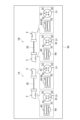
- FIG. 23 is a diagram showing an optical transmission system 90 including connectorized optical fiber cables 1A and 1B (hereinafter simply referred to as cables 1A and 1B) as a first modification of the above embodiment.
- the cables 1A and 1B have, as the first optical connector 3 and the second optical connector 4, optical connectors (e.g., MPO connectors 60) that are connected in an inverted upward direction to the mating optical connector.
- the first cable 1A has the arrangement of the cores 32 shown in Fig. 10.
- the second cable 1B has the arrangement of the cores 32 shown in Fig. 13.
- the appearance of cable 1B may be different from that of cable 1A in order to easily distinguish between cables 1A and 1B.
- different appearances may mean that the color of the coating resin of the optical fiber cable 30 is different, the color of the resin housing 61 of the MPO connector 60 is different, the colors of the boots 16, 26, and 66 are different, etc.
- FIGS. 24A, 24B, 25A, and 25B are diagrams showing an example of an optical connector (e.g., MPO connector 60) in which the first optical connector 3 and the second optical connector 4 are connected in a state in which the upward direction is inverted relative to the mating optical connector, and the end faces of the first optical fiber 31 to the Mth optical fiber 31 are arranged in multiple rows (e.g., two rows) on the connection end face 71.
- Each of Figs. 24A and 25A shows the connection end face 71 of the first optical connector 3, and each of Figs. 24B and 25B shows the connection end face 71 of the second optical connector 4.
- the numbers with "#" indicate the numbers of the optical fibers 31.
- the arrangement of the end faces of the first optical fiber 31 to the Mth optical fiber 31 at the connection end face 71 of the second optical connector 4 is an arrangement that is upside down of the arrangement of the end faces of the first optical fiber 31 to the Mth optical fiber 31 at the connection end face 71 of the first optical connector 3. Also, in the example shown in FIG.
- connection end faces 71 of the first optical connector 3 and the second optical connector 4 when the connection end faces 71 of the first optical connector 3 and the second optical connector 4 are viewed with the optical connectors facing upwards, the arrangement of the end faces of the first optical fiber 31 to the Mth optical fiber 31 at the connection end face 71 of the second optical connector 4 is the same as the arrangement of the end faces of the first optical fiber 31 to the Mth optical fiber 31 at the connection end face 71 of the first optical connector 3.
- the structures of the portions of the first optical connector 3 and the second optical connector 4 that fit with the optical connector of the connection partner may be different from each other.
- the housing 11 of either the first optical connector 3 or the second optical connector 4 may have a recess (key groove) instead of the protrusion 15.
- the housing 61 of either the first optical connector 3 or the second optical connector 4 may have a recess (key groove) instead of the protrusion 65.
- the guide pin to be inserted into the guide pin hole 72 may be prepared in advance only in either the first optical connector 3 or the second optical connector 4. In this way, the structures of the portions of the first optical connector 3 and the second optical connector 4 that fit with the optical connector of the connection partner are different from each other, so that the first optical connector 3 and the second optical connector 4 can be easily identified.
- the connectorized optical fiber cable and optical transmission system are not limited to the above-described embodiments, and various other modifications are possible.
- the SC connector 10 and the LC connector 20 are given as examples of optical connectors that are connected with the mating optical connector facing in the same direction, but various other optical connectors other than the SC connector 10 and the LC connector 20 can be used as such optical connectors.
- the MPO connector 60 is given as an example of an optical connector that is connected with the mating optical connector facing in the opposite direction, but various other optical connectors other than the MPO connector 60 can be used as such optical connectors.
Landscapes
- Physics & Mathematics (AREA)
- General Physics & Mathematics (AREA)
- Optics & Photonics (AREA)
- Mechanical Coupling Of Light Guides (AREA)
Priority Applications (3)
| Application Number | Priority Date | Filing Date | Title |
|---|---|---|---|
| CN202380076080.6A CN120202431A (zh) | 2022-12-09 | 2023-11-09 | 带连接器的光缆和光传输系统 |
| JP2024562639A JPWO2024122265A1 (https=) | 2022-12-09 | 2023-11-09 | |
| EP23900386.6A EP4632454A1 (en) | 2022-12-09 | 2023-11-09 | Connector-equipped optical fiber cable and optical transmission system |
Applications Claiming Priority (2)
| Application Number | Priority Date | Filing Date | Title |
|---|---|---|---|
| JP2022196942 | 2022-12-09 | ||
| JP2022-196942 | 2022-12-09 |
Publications (1)
| Publication Number | Publication Date |
|---|---|
| WO2024122265A1 true WO2024122265A1 (ja) | 2024-06-13 |
Family
ID=91378972
Family Applications (1)
| Application Number | Title | Priority Date | Filing Date |
|---|---|---|---|
| PCT/JP2023/040406 Ceased WO2024122265A1 (ja) | 2022-12-09 | 2023-11-09 | コネクタ付き光ファイバケーブルおよび光伝送システム |
Country Status (4)
| Country | Link |
|---|---|
| EP (1) | EP4632454A1 (https=) |
| JP (1) | JPWO2024122265A1 (https=) |
| CN (1) | CN120202431A (https=) |
| WO (1) | WO2024122265A1 (https=) |
Citations (5)
| Publication number | Priority date | Publication date | Assignee | Title |
|---|---|---|---|---|
| JPS6333102U (https=) * | 1986-08-20 | 1988-03-03 | ||
| WO2017077050A1 (en) * | 2015-11-06 | 2017-05-11 | CommScope Connectivity Belgium BVBA | Optical fiber alignment mechanisms |
| US10859772B1 (en) | 2019-09-23 | 2020-12-08 | Ofs Fitel, Llc | Routing of multicore optical fibers in data networks |
| JP2022055678A (ja) * | 2020-09-29 | 2022-04-08 | Kddi株式会社 | マルチコア光ファイバの接続器 |
| WO2022118985A1 (ja) | 2020-12-04 | 2022-06-09 | 株式会社フジクラ | ファイバ接続体、光通信システム、光デバイス、及び、ファイバ接続体の製造方法 |
-
2023
- 2023-11-09 EP EP23900386.6A patent/EP4632454A1/en active Pending
- 2023-11-09 WO PCT/JP2023/040406 patent/WO2024122265A1/ja not_active Ceased
- 2023-11-09 CN CN202380076080.6A patent/CN120202431A/zh active Pending
- 2023-11-09 JP JP2024562639A patent/JPWO2024122265A1/ja active Pending
Patent Citations (5)
| Publication number | Priority date | Publication date | Assignee | Title |
|---|---|---|---|---|
| JPS6333102U (https=) * | 1986-08-20 | 1988-03-03 | ||
| WO2017077050A1 (en) * | 2015-11-06 | 2017-05-11 | CommScope Connectivity Belgium BVBA | Optical fiber alignment mechanisms |
| US10859772B1 (en) | 2019-09-23 | 2020-12-08 | Ofs Fitel, Llc | Routing of multicore optical fibers in data networks |
| JP2022055678A (ja) * | 2020-09-29 | 2022-04-08 | Kddi株式会社 | マルチコア光ファイバの接続器 |
| WO2022118985A1 (ja) | 2020-12-04 | 2022-06-09 | 株式会社フジクラ | ファイバ接続体、光通信システム、光デバイス、及び、ファイバ接続体の製造方法 |
Non-Patent Citations (1)
| Title |
|---|
| See also references of EP4632454A1 |
Also Published As
| Publication number | Publication date |
|---|---|
| JPWO2024122265A1 (https=) | 2024-06-13 |
| CN120202431A (zh) | 2025-06-24 |
| EP4632454A1 (en) | 2025-10-15 |
Similar Documents
| Publication | Publication Date | Title |
|---|---|---|
| US8272788B2 (en) | Optical-path turning device | |
| US7184635B2 (en) | Optical fiber array connectivity system utilizing angle polished ferrules and aligned-key adapters and cable for same | |
| US7416347B2 (en) | Optical fiber array connectivity system with indicia to facilitate connectivity in four orientations for dual functionality | |
| JP7010244B2 (ja) | 光接続部品及び光結合構造 | |
| US10775569B2 (en) | Optical connector and optical connection structure | |
| EP4571374A1 (en) | Multicore fiber, optical device, and method for manufacturing multicore fiber | |
| JP2025020464A (ja) | マルチコアファイバ、及び光デバイス | |
| WO2024122265A1 (ja) | コネクタ付き光ファイバケーブルおよび光伝送システム | |
| US11150418B2 (en) | Optical connector ferrule and optical connector | |
| WO2024134775A1 (ja) | 光コネクタおよび光コネクタユニット | |
| JP7451315B2 (ja) | 光コネクタフェルール、光コネクタ、光接続構造、およびレンズアレイの製造方法 | |
| JPWO2024122265A5 (https=) | ||
| WO2025075063A1 (ja) | 光コネクタ、光接続アセンブリ、光導波路部材、および光コネクタの製造方法 | |
| JP7591600B2 (ja) | マルチコアファイバ、光デバイス、ファンイン/ファンアウトデバイス、及びマルチコアファイバ集合体 | |
| JP2022028382A (ja) | レンズプレート、レンズフェルール及びレンズコネクタ | |
| US20230251433A1 (en) | Fiber positioning arrangement for optical fibers | |
| WO2025075062A1 (ja) | 光コネクタ、光接続アセンブリ、および光コネクタの製造方法 | |
| WO2025150374A1 (ja) | 保持部材、光ファイバ接続部品、光コネクタ、接続アセンブリ、および光ファイバ接続部品の製造方法 | |
| WO2024028954A1 (ja) | 光コネクタ及び製造方法 | |
| JP2022110860A (ja) | フェルール、光コネクタ及び光接続構造 | |
| JPH10239563A (ja) | 多心光コネクタ |
Legal Events
| Date | Code | Title | Description |
|---|---|---|---|
| 121 | Ep: the epo has been informed by wipo that ep was designated in this application |
Ref document number: 23900386 Country of ref document: EP Kind code of ref document: A1 |
|
| WWE | Wipo information: entry into national phase |
Ref document number: 2024562639 Country of ref document: JP |
|
| WWE | Wipo information: entry into national phase |
Ref document number: 202380076080.6 Country of ref document: CN |
|
| WWP | Wipo information: published in national office |
Ref document number: 202380076080.6 Country of ref document: CN |
|
| WWE | Wipo information: entry into national phase |
Ref document number: 2023900386 Country of ref document: EP |
|
| NENP | Non-entry into the national phase |
Ref country code: DE |
|
| ENP | Entry into the national phase |
Ref document number: 2023900386 Country of ref document: EP Effective date: 20250709 |
|
| WWP | Wipo information: published in national office |
Ref document number: 2023900386 Country of ref document: EP |