WO2024122034A1 - 位置合わせ装置 - Google Patents
位置合わせ装置 Download PDFInfo
- Publication number
- WO2024122034A1 WO2024122034A1 PCT/JP2022/045345 JP2022045345W WO2024122034A1 WO 2024122034 A1 WO2024122034 A1 WO 2024122034A1 JP 2022045345 W JP2022045345 W JP 2022045345W WO 2024122034 A1 WO2024122034 A1 WO 2024122034A1
- Authority
- WO
- WIPO (PCT)
- Prior art keywords
- pressing member
- robot
- holes
- hole
- finger
- Prior art date
- Legal status (The legal status is an assumption and is not a legal conclusion. Google has not performed a legal analysis and makes no representation as to the accuracy of the status listed.)
- Ceased
Links
Images




Classifications
-
- B—PERFORMING OPERATIONS; TRANSPORTING
- B25—HAND TOOLS; PORTABLE POWER-DRIVEN TOOLS; MANIPULATORS
- B25J—MANIPULATORS; CHAMBERS PROVIDED WITH MANIPULATION DEVICES
- B25J15/00—Gripping heads and other end effectors
- B25J15/08—Gripping heads and other end effectors having finger members
-
- B—PERFORMING OPERATIONS; TRANSPORTING
- B25—HAND TOOLS; PORTABLE POWER-DRIVEN TOOLS; MANIPULATORS
- B25B—TOOLS OR BENCH DEVICES NOT OTHERWISE PROVIDED FOR, FOR FASTENING, CONNECTING, DISENGAGING, OR HOLDING
- B25B11/00—Work holders not covered by any preceding group in the subclass, e.g. magnetic work holders, vacuum work holders
-
- B—PERFORMING OPERATIONS; TRANSPORTING
- B23—MACHINE TOOLS; METAL-WORKING NOT OTHERWISE PROVIDED FOR
- B23Q—DETAILS, COMPONENTS, OR ACCESSORIES FOR MACHINE TOOLS, e.g. ARRANGEMENTS FOR COPYING OR CONTROLLING; MACHINE TOOLS IN GENERAL CHARACTERISED BY THE CONSTRUCTION OF PARTICULAR DETAILS OR COMPONENTS; COMBINATIONS OR ASSOCIATIONS OF METAL-WORKING MACHINES, NOT DIRECTED TO A PARTICULAR RESULT
- B23Q3/00—Devices holding, supporting, or positioning work or tools, of a kind normally removable from the machine
- B23Q3/18—Devices holding, supporting, or positioning work or tools, of a kind normally removable from the machine for positioning only
- B23Q3/183—Centering devices
-
- B—PERFORMING OPERATIONS; TRANSPORTING
- B25—HAND TOOLS; PORTABLE POWER-DRIVEN TOOLS; MANIPULATORS
- B25B—TOOLS OR BENCH DEVICES NOT OTHERWISE PROVIDED FOR, FOR FASTENING, CONNECTING, DISENGAGING, OR HOLDING
- B25B1/00—Vices
- B25B1/06—Arrangements for positively actuating jaws
- B25B1/18—Arrangements for positively actuating jaws motor driven, e.g. with fluid drive, with or without provision for manual actuation
Definitions
- This disclosure relates to an alignment device.
- the process of manufacturing products there is a process of stacking multiple workpieces and then aligning the holes formed in the workpieces. For example, after aligning the holes, bolts may be inserted into the holes to secure multiple workpieces to one another. Or, the holes may be aligned and rod-shaped members such as pins or shafts may be inserted into the holes in the workpieces.
- the positions of the multiple holes are misaligned, it may not be possible to smoothly insert components such as bolts or shafts. For this reason, the positions of the multiple holes must be precisely aligned when viewed from the axial direction.
- a device in which a hole clamp that holds the hole is inserted into the hole to align the hole in multiple workpieces, and the clamping force is used to align the hole.
- the hole clamp is large, it may not be possible to insert the hole clamp into the hole.
- a method is known in which an air chuck is used to align the hole in multiple workpieces. The fingers of the air chuck are inserted into the hole.
- a device is known in which the fingers are then opened to align the hole.
- the fingers may become deformed or damaged if the diameter of the holes is small because the rigidity of the fingers cannot be increased. Or, the fingers may become deformed or damaged if a large opening force is required for the air chuck. If the fingers are damaged, they must be replaced. Thus, when an air chuck is used as a device for aligning holes, there is a problem in that the durability of the device is low.
- the alignment device of one embodiment of the present disclosure includes a plurality of finger portions formed to be movable in a radial direction perpendicular to the axial direction, and a wedge-shaped pressing member arranged to contact the plurality of finger portions.
- the alignment device includes a moving device that moves the pressing member in the axial direction. With the finger portions inserted inside the holes of the plurality of workpieces, the moving device moves the pressing member, causing the finger portions to move radially outward, thereby aligning the positions of the holes of the plurality of workpieces.
- FIG. 1 is a schematic perspective view of a robot device according to an embodiment.
- FIG. 1 is a block diagram of a robot device according to an embodiment.
- FIG. 2 is a perspective view of a work tool according to an embodiment.
- 1 is a schematic cross-sectional view of a work tool according to an embodiment.
- 10 is an enlarged schematic cross-sectional view of a first step of aligning the positions of holes in the work tool according to the embodiment;
- FIG. FIG. 11 is an enlarged schematic cross-sectional view of a second step of aligning the positions of the holes in the work tool according to the embodiment.
- 11 is an enlarged schematic cross-sectional view of the working tool according to the embodiment when the position of the hole is adjusted.
- FIG. 1 is a schematic perspective view of a robot device according to an embodiment.
- FIG. 1 is a block diagram of a robot device according to an embodiment.
- FIG. 2 is a perspective view of a work tool according to an embodiment.
- 1 is a schematic cross-
- FIG. 11 is an enlarged schematic cross-sectional view of a first step of aligning the positions of holes in the alignment device of the comparative example.
- FIG. FIG. 11 is an enlarged schematic cross-sectional view of a second step of aligning the positions of holes in the alignment device of the comparative example.
- FIG. 2 is a plan view of two plate-shaped workpieces stacked one on top of the other. 13 is an enlarged view of an image of a hole when two workpieces are overlapped.
- FIG. FIG. 11 is a schematic cross-sectional view of another alignment device in the embodiment.
- the alignment device according to this embodiment adjusts the relative positions of multiple workpieces so that holes formed in each workpiece are aligned when the workpieces are stacked.
- FIG. 1 is a perspective view of a robot device in this embodiment.
- the robot device 5 in this embodiment includes a robot 1 and a work tool 2.
- the robot device 5 includes a control device 4 that controls the robot 1 and the work tool 2.
- the work tool 2 attached to the robot 1 corresponds to the alignment device.
- the robot device 5 changes the position and posture of the alignment device, and inserts the fingers of the alignment device into the holes of multiple workpieces 85, 86.
- the alignment device then aligns the holes with each other.
- the robot 1 of this embodiment is a multi-joint robot including multiple joints.
- the robot 1 includes an upper arm 11 and a lower arm 12.
- the lower arm 12 is supported by a swivel base 13.
- the swivel base 13 is supported by a base 14.
- the robot 1 includes a wrist 15 that is connected to the end of the upper arm 11.
- the wrist 15 includes a flange 16 to which a work tool 2 is attached and which is formed to be rotatable.
- the robot 1 is configured to rotate around a predetermined axis of rotation.
- the robot in this embodiment has six drive axes, but is not limited to this form. Any robot that can change the position and posture of the work tool can be used.
- the work tool 2 in this embodiment functions as an alignment device that aligns the positions of holes formed in multiple workpieces.
- Workpieces 85, 86 in this embodiment are formed in a plate shape. Workpieces 85, 86 are placed on stands 81, 82. Workpieces 85, 86 are arranged so that their maximum area faces extend in the horizontal direction. As described below, holes 85a, 85b are formed in workpiece 85. Holes 86a, 86b are formed in workpiece 86.
- workpieces 85 and 86 have the same shape.
- the position of hole 85a and the position of hole 86a almost coincide.
- Hole 85a and hole 86a have the same shape.
- the position of hole 85b and the position of hole 86b almost coincide.
- Hole 85b and hole 86b have the same shape.
- the positions of the holes may be slightly misaligned.
- the robot device 5 uses the work tool 2 to adjust the relative position of the workpiece 86 with respect to the workpiece 85 so that the positions of the holes match when viewed from above. After this, for example, another robot device performs the work of inserting a member such as a bolt or pin into the hole.
- the robot device 5 of this embodiment is equipped with a camera 6 as a visual sensor for detecting the positions of holes in the workpieces 85 and 86.
- the position of the camera 6 of this embodiment is fixed by a support member 83.
- the camera 6 of this embodiment is a two-dimensional camera.
- the camera 6 is controlled by the control device 4.
- the camera 6 of this embodiment captures images of the workpieces 85 and 86.
- the camera 6 is positioned so that it captures an image directly below. In other words, the camera 6 is fixed so that its optical axis extends vertically.
- the distance from the workpieces 85, 86 to the camera 6 is determined and measured. Therefore, the three-dimensional position can be detected based on the position in the two-dimensional image captured by the camera 6. For example, a reference image 46 of the hole 85a can be stored in the memory unit 42. Then, the three-dimensional position of the hole 85a can be detected by pattern matching of the image captured by the camera 6.
- a reference coordinate system 37 is set that remains stationary when the position and posture of the robot 1 change.
- the origin of the reference coordinate system 37 is located on the base 14 of the robot 1.
- the reference coordinate system 37 is also called the world coordinate system.
- the robot device 5 is set with a tool coordinate system 38 having an origin set at an arbitrary position on the work tool 2.
- the position and orientation of the tool coordinate system 38 change together with the work tool 2.
- the origin of the tool coordinate system 38 is set at the tool tip point.
- the position of the robot 1 corresponds to the position of the tool tip point (the position of the origin of the tool coordinate system 38).
- the orientation of the robot 1 corresponds to the orientation of the tool coordinate system 38 with respect to the reference coordinate system 37.
- a camera coordinate system 39 is set with respect to the camera 6.
- the camera coordinate system 39 is a coordinate system whose origin is fixed to the camera 6.
- the position of the camera 6 is fixed, and therefore the position of the camera coordinate system 39 is fixed.
- the camera coordinate system 39 is set so that the Z axis of the camera coordinate system 39 coincides with the optical axis.
- Each coordinate system has an X-axis, a Y-axis, and a Z-axis that are perpendicular to each other.
- the W-axis may be set as the coordinate axis around the X-axis
- the P-axis as the coordinate axis around the Y-axis
- the R-axis as the coordinate axis around the Z-axis.
- FIG. 2 shows a block diagram of the robot device in this embodiment.
- the robot 1 includes a robot driving device 22 that changes the position and posture of the robot 1.
- the robot driving device 22 includes a driving motor that drives components such as an arm and a wrist. The orientation of each component changes as the robot driving device 22 drives it.
- the robot device 5 includes a tool driving device 21 that drives the work tool 2.
- the work tool 2 is driven by air pressure.
- the tool driving device 21 in this embodiment includes a cylinder, a solenoid valve, and the like.
- the control device 4 controls the operation of the robot 1 and the work tool 2.
- the control device 4 is equipped with an arithmetic processing device (computer) including a CPU (Central Processing Unit) as a processor.
- the arithmetic processing device has a RAM (Random Access Memory) and a ROM (Read Only Memory), etc., which are connected to the CPU via a bus.
- the robot device 5 of this embodiment adjusts the relative position of the hole in the workpiece 86 with respect to the hole in the workpiece 85 based on the operation program 41.
- the robot driving device 22 and the tool driving device 21 are controlled by the control device 4.
- the control device 4 includes a memory unit 42 that stores information related to the control of the robot device 5.
- the memory unit 42 can be configured with a non-transitory storage medium capable of storing information.
- the memory unit 42 can be configured with a storage medium such as a volatile memory, a non-volatile memory, a magnetic storage medium, or an optical storage medium.
- the operation program 41 is stored in the memory unit 42.
- the operation control unit 43 sends operation commands to the robot driving unit 45 for driving the robot 1 based on the operation program 41.
- the robot driving unit 45 includes an electric circuit that drives the robot driving device 22.
- the robot driving unit 45 supplies electricity to the robot driving device 22 based on the operation commands.
- the operation control unit 43 also sends an operation command to the tool driving unit 44 to drive the work tool 2 based on the operation program 41.
- the tool driving unit 44 includes an electrical circuit that drives the tool driving device 21.
- the tool driving unit 44 supplies electricity to the tool driving device 21 based on the operation command.
- the operation control unit 43 also sends an operation command to the camera 6 to drive the camera 6 based on the operation program 41.
- the camera 6 captures an image based on the operation command.
- the operation control unit 43 corresponds to a processor that operates according to the operation program 41.
- the processor is configured to be able to read information stored in the storage unit 42.
- the processor reads the operation program 41 and performs the control defined in the operation program 41, thereby functioning as the operation control unit 43.
- the robot 1 includes a state detector for detecting the position and posture of the robot 1.
- the state detector includes a position detector 18 attached to a drive motor of the robot drive device 22 that corresponds to the drive shaft of a component such as an arm.
- the position and posture of the robot 1 are calculated based on the output of the position detector 18.
- the control device 4 in this embodiment includes an image processing unit 51 that processes images captured by the camera 6.
- the image processing unit 51 has a position detection unit 52 that detects the three-dimensional position of the target part based on the images acquired by the camera 6.
- the position detection unit 52 detects the position of the hole in the workpiece.
- the position of the hole in the workpiece can be detected as the center position of the planar shape of the hole in a surface including the top surface of the workpiece.
- a reference image 46 of the workpiece is stored in advance in the storage unit 42.
- a reference image 46 of the hole in the workpiece is stored in advance in the storage unit 42.
- the position detection unit 52 can detect the position of the hole in the image by performing pattern matching on the image captured by the camera 6 using the reference image 46.
- the position detection unit 52 can detect the three-dimensional position of the hole based on the position of the hole in the two-dimensional image captured by the camera 6. For example, the position of the center of the planar shape of the hole 85a of the workpiece 85 can be calculated in the camera coordinate system 39.
- the camera coordinate system 39 in this embodiment is fixed.
- the position and orientation of the camera coordinate system 39 in the reference coordinate system 37 are determined in advance. Therefore, the position detection unit 52 can convert the position and orientation of the hole in the camera coordinate system 39 to the position and orientation of the hole in the reference coordinate system 37.
- the image processing unit 51 has a command generating unit 53 that generates a motion command for the robot 1 based on the position of the hole detected by the position detecting unit 52.
- the command generating unit 53 generates a motion command to move the tool tip point vertically after placing the tool tip point at the center position of the hole.
- the motion command generated by the command generating unit 53 is sent to the motion control unit 43.
- the motion control unit 43 drives the robot 1 and the work tool 2 based on the motion command generated by the command generating unit 53.
- Each of the image processing unit 51, position detection unit 52, and command generation unit 53 corresponds to a processor that operates according to a predetermined program.
- the processor reads the program and performs the control defined in the program, thereby functioning as each unit.
- FIG. 3 shows a perspective view of the work tool in this embodiment.
- FIG. 4 shows an enlarged schematic cross-sectional view of the work tool in this embodiment.
- FIG. 4 is a cross-sectional view taken in the radial direction at the position of multiple fingers.
- FIG. 4 also shows the state of the work tool before the hole alignment is performed.
- the direction in which the pressing member 68 moves is referred to as the axial direction.
- the direction in which the axis 88 of the central shaft extends is referred to as the axial direction.
- the direction perpendicular to the axial direction is referred to as the radial direction.
- the work tool 2 includes a plurality of finger portions 74 formed to be movable in the radial direction. In this embodiment, three finger portions 74 are arranged. The finger portions 74 are fixed to the slide member 73. The slide member 73 is formed to be slidable in the radial direction relative to the second cylinder case 64. The finger portions 74 move integrally with the slide member 73.
- the work tool 2 has a pressing member 68 for moving the multiple finger portions 74 in the radial direction.
- the pressing member 68 has a wedge-shaped cross section.
- the pressing member 68 is formed in a cone shape.
- the pressing member 68 is positioned so as to come into contact with the inner surfaces of the multiple finger portions 74.
- Each finger portion 74 has an upright portion 74a extending along the axis 88.
- the upright portion 74a has an inclined surface 74aa on the inside.
- the inclined surface 74aa is in close contact with the inclined surface 68a, which is the outer peripheral surface of the pressing member 68.
- the pressing member 68 has a shape that tapers in the direction toward the tip of the upright portion 74a. In this way, the pressing member 68 is sandwiched between the multiple finger portions 74 and is formed so as to be in close contact with the inner peripheral surfaces of the multiple finger portions 74.
- the work tool 2 is configured such that the finger portion 74 opens and closes as the pressing member 68 moves in the direction of the axis 88.
- the work tool 2 includes a first cylinder 60 that moves the pressing member 68 in the axial direction, and a second cylinder 63 that biases the finger portion 74.
- the first cylinder 60 includes a first cylinder case 61 having a hollow portion 62 therein.
- a first piston 66 is disposed inside the hollow portion 62.
- the first cylinder 60 functions as a moving device that moves the pressing member 68 in the axial direction.
- the first piston 66 is connected to the first shaft 67.
- the pressing member 68 is fixed to the first shaft 67.
- Air chambers 62a and 62b are formed in the cavity 62 for moving the first piston 66.
- the first piston 66 moves along the axis 88 by supplying compressed air to either the air chamber 62a or the air chamber 62b and releasing air from the other air chamber (opening the air chamber).
- the first piston 66, the first shaft 67, and the pressing member 68 move together.
- the second cylinder 63 functions as a biasing device that biases the finger portion 74 radially inward.
- the second cylinder 63 includes a second cylinder case 64 having a hollow portion 65 therein.
- a second piston 71 is disposed inside the hollow portion 65.
- a second shaft 72 is fixed to the second piston 71.
- the second piston 71 and the second shaft 72 are formed so as to be axially slidable relative to the first shaft 67.
- a tip portion 72a is formed at the tip of the second shaft 72.
- the tip portion 72a is formed in the shape of a truncated cone.
- the tip portion 72a has an inclined surface 72aa, which is the outer circumferential surface.
- the second piston 71 and the second shaft 72 are formed to move integrally in the axial direction.
- the slide member 73 has an inclined surface 73a on the radially inner side.
- the inclined surface 72aa of the tip portion 72a is formed to contact the inclined surface 73a of the slide member 73.
- the tip portion 72a also has a mechanism for hooking the slide member 73 and biasing the slide member 73 radially inward when it moves in a direction away from the finger portion 74. That is, the inclined surface 72aa of the tip portion 72a is formed to slide against the inclined surface 73a of the slide member 73 and engage with the inclined surface 73a to pull the slide member 73 radially inward.
- a sealing member 78a that blocks the flow of air is disposed on the outer circumferential surface of the first piston 66. Furthermore, a sealing member 78b is disposed on the outer circumferential surface of the first shaft 67, a sealing member 78c is disposed on the outer circumferential surface of the second piston 71, and a sealing member 78d is disposed on the outer circumferential surface of the second shaft 72.
- Air chamber 62b In the state shown in FIG. 4, compressed air is supplied to air chamber 62b. Air chamber 62a is open. Compressed air is supplied to air chamber 65b. Air chamber 65a is open. First piston 66 is moving in a direction away from finger portion 74. Pressing member 68 is positioned in a retracted position.
- the second piston 71 is biased in a direction away from the finger portion 74.
- the slide member 73 is pulled by the inclined surface 72aa of the tip portion 72a of the second shaft 72 and biased radially inward.
- the finger portion 74 is biased radially inward together with the slide member 73.
- the multiple finger portions 74 are in a closed state.
- the inclined surface 74aa of the erect portion 74a is in close contact with the inclined surface 68a of the pressing member 68. In this state, the robot 1 is driven to insert the erect portion 74a of the finger portion 74 into the holes 85a and 86a.
- FIG. 5 shows an enlarged schematic cross-sectional view illustrating the process of aligning holes.
- FIG. 5 corresponds to the state of the work tool in FIG. 4.
- the position of hole 85a in workpiece 85 and the position of hole 86a in workpiece 86 are slightly misaligned in the radial direction.
- the position of hole 85a and the position of hole 86a are misaligned in the horizontal direction.
- the control device 4 inserts the erected portions 74a of the finger portion 74 into the holes 85a and 86a.
- the position detection unit 52 of the control device 4 can detect the position of the hole 85a by analyzing the image of the top surface of the workpiece 85 captured by the camera 6.
- the command generation unit 53 drives the robot 1 so that the tool tip point of the work tool 2 is positioned at the position of the hole 85a.
- the tip point of the pressing member 68 is positioned at the center position of the hole 85a on the top surface of the workpiece 85.
- the command generation unit 53 can insert the erected portions 74a of the finger portion 74 into the holes 85a and 86a by moving the work tool 2 downward in the vertical direction.
- the positions at which the workpieces 85, 86 are placed relative to the stands 81, 82 are determined in advance. For this reason, the positions of the holes 85a, 86a are determined in advance, although they include some margin of error.
- the memory unit 42 of the control device 4 can store the position and posture of the robot in which the erected portion 74a of the work tool 2 is inserted into the holes 85a, 86a. Then, the control device 4 drives the robot 1, so that the erected portion 74a at the tip of the work tool 2 is inserted into the holes 85a, 86a.
- the tool driving device 21 bleeds air from the air chamber 62b of the first cylinder 60 and supplies compressed air to the air chamber 62a.
- the tool driving device 21 also performs control to bleed air from the air chamber 65b of the second cylinder 63.
- the first piston 66, the first shaft 67, and the pressing member 68 move in the direction indicated by the arrow 91.
- the second piston 71 and the second shaft 72 move in the direction indicated by the arrow 95.
- the pressing member 68 moves in the direction indicated by the arrow 91.
- the inclined surface 68a of the pressing member 68 presses the inclined surface 74aa of the finger portion 74.
- the finger portion 74 moves radially outward as indicated by the arrow 92. In this manner, the multiple finger portions 74 perform an opening operation.
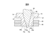
- Figure 6 shows an enlarged schematic cross-sectional view of the finger portion when it is opened.
- finger portion 74 opens, the outer peripheral surface of finger portion 74 comes into contact with holes 85a and 86a. Because finger portion 74 is driven by a predetermined driving force, the opening action of finger portion 74 stops.
- the positions of holes 85a and 86a are aligned along the axial direction. In other words, when viewed in a plan view, the positions of holes 85a and 86a match. The alignment of the holes has been completed.
- FIG. 7 shows a schematic cross-sectional view of the work tool when the alignment of the holes is complete.
- compressed air is supplied to the air chamber 62a of the first cylinder 60, so that the first piston 66, the first shaft 67, and the pressing member 68 are positioned at the most protruding position of the pressing member 68.
- the air chamber 65b of the second cylinder 63 is opened, so that the positions of the second piston 71 and the second shaft 72 also change in accordance with the radial outward movement of the finger portion 74.
- the tool driving device 21 supplies compressed air to the air chamber 62b of the first cylinder 60 and releases air from the air chamber 62a. This operation moves the first piston 66, the first shaft 67, and the pressing member 68 in the direction indicated by the arrow 96.
- the second piston 71 and the second shaft 72 are urged in the direction shown by arrow 98.
- the slide member 73 and the finger portion 74 move radially inward as shown by arrow 97 due to the movement of the second shaft 72.
- the slide member 73 and the finger portion 74 are urged radially inward due to the movement of the second shaft 72.
- the control device 4 controls the position and posture of the robot 1 so that the work tool 2 retreats from the workpieces 85, 86. Then, after aligning the holes 85a, 86a, a bolt, pin, or the like can be inserted into the holes 85a, 86a.
- Figure 8 shows an enlarged schematic cross-sectional view of the tip of the alignment device of the comparative example.
- the alignment device of the comparative example has fingers 89 that move radially relative to each other.
- the fingers 89 are configured to move by a chuck device. In other words, the fingers 89 are not pressed by a wedge-shaped pressing member, but are connected to a cylinder or the like and move radially.
- the chuck device is driven, and finger portion 89 moves in the direction indicated by arrow 92. Then, standing portion 89a comes into contact with holes 85a and 85b, thereby enabling alignment with holes 85a and 86a.
- FIG. 9 shows an enlarged schematic cross-sectional view of the alignment device of the comparative example when hole alignment is complete.
- spaces 90 are formed between multiple finger portions 89.
- the finger portions 89 are driven in the direction indicated by the arrow 92.
- a pressing member 68 is disposed in an area surrounded by a plurality of finger portions 74.
- the finger portions 74 are in contact with the pressing member 68. This makes it possible to prevent bending stress from being applied to the finger portions 74 when they are driven. As a result, the alignment device of this embodiment is less likely to break. In other words, the durability of the alignment device is improved.
- the moving device including the first cylinder 60 is configured to push the pressing member 68, thereby moving the multiple finger portions 74 radially outward, but this is not limited to the embodiment.
- the moving device may be configured to move the pressing member 68 in the direction indicated by the arrow 91 by pulling the pressing member 68.
- the pressing member 68 is configured to move by the first cylinder 60, but this is not limited to the embodiment.
- the moving device may be configured to move the pressing member 68 by a member such as a motor or a spring.
- the biasing device that biases the finger portion 74 radially inward is not limited to the second cylinder 63.
- the biasing device may be configured to bias the finger portion radially inward by a member such as a motor or a spring.
- control device 4 has an image processing unit 51 that processes images from the camera 6.
- the camera 6 captures images of the workpieces 85 and 86 to detect the positions of the holes 85a and 86a.
- FIG. 10 shows a plan view of multiple workpieces in this embodiment.
- the positions of the two workpieces 85, 86 may be slightly misaligned.
- hole 86a is misaligned relative to hole 85a.
- hole 86b is misaligned relative to hole 85b.
- FIG. 11 shows an enlarged view of the hole portion in the image captured by the camera.
- FIG. 11 shows an enlarged view of the images of hole portion 85a and hole portion 86a.
- position detection unit 52 of image processing unit 51 detects center point 85aa of hole portion 85a when viewed in a plane by pattern matching of hole portion 85a.
- the image of camera 6 includes the circular arc of hole portion 86a of workpiece 86. By detecting the circular arc, position detection unit 52 can detect center point 86aa of hole portion 86a in the image.
- the position detection unit 52 converts the coordinate values of the camera coordinate system 39 into coordinate values of the reference coordinate system 37.
- the position of the center point 85aa and the position of the center point 86aa on the upper surface of the workpiece 85 can be calculated.
- the command generation unit 53 calculates the midpoint 87 between the center points 85aa and 86aa.
- the command generation unit 53 can then control the position and attitude of the robot 1 so that the tool tip point of the work tool 2 is positioned at the position of the midpoint 87 on the upper surface of the workpiece 85.
- the position and attitude of the robot can be controlled so that the tool tip point of the work tool 2 moves downward in the vertical direction.
- the erected portion 74a of the finger portion 74 of the work tool 2 can be reliably inserted inside the multiple holes 85a, 86a.
- Figure 12 shows a schematic cross-sectional view of another work tool in this embodiment.
- the other work tool 7 in this embodiment includes a finger portion 76 having an upright portion 76a. Most of the inner peripheral surface of the upright portion 76a is not in contact with the pressing member 68. A part of the inclined surface 76aa of the upright portion 76a is formed so as to be in contact with the inclined surface 68a of the pressing member 68.
- the pressing member 68 is disposed in a portion surrounded by multiple finger portions 76, so bending stress on the finger portions 76 can be suppressed. As a result, the durability of the work tool 7 can be improved.
- the alignment device of this embodiment has three fingers, but is not limited to this form and can be configured with multiple fingers.
- the pressing member of this embodiment has a conical shape, but is not limited to this form.
- the pressing member may have a pyramidal shape according to the number of fingers.
- the camera 6 as a visual sensor is fixed to the support member 83, but is not limited to this form.
- the visual sensor can be positioned so as to be able to capture an image of the workpiece.
- the visual sensor may be fixed to the wrist of the robot so as to move integrally with the wrist.
- the position and orientation of the camera coordinate system on the robot can be calculated in advance. Then, based on the position and orientation of the robot, information on the position of the hole detected in the camera coordinate system can be converted into information on the position of the hole in the reference coordinate system.
- the camera 6 is a two-dimensional camera, but is not limited to this form.
- the visual sensor may be a three-dimensional camera capable of acquiring three-dimensional position information.
- the visual sensor may be a stereo camera including two two-dimensional cameras.
- control device includes an image processing unit, but this is not limited to the above.
- the image processing unit may be configured as a processing device (computer) that is different from the control device that controls the robot's operation.
- a computer that functions as the image processing unit may be configured to communicate with the control device that controls the robot.
- control for aligning the positions of holes in two workpieces is described as an example, but this is not limited to this form, and the control of this embodiment can also be implemented when aligning the positions of holes in three or more workpieces.
- Each finger portion has a standing portion 74a, 76a extending in the axial direction,
- the pressing member is formed so as to become thinner in a direction toward the tip of the erected portion, 2.
Landscapes
- Engineering & Computer Science (AREA)
- Mechanical Engineering (AREA)
- Robotics (AREA)
- Manipulator (AREA)
- Jigs For Machine Tools (AREA)
Priority Applications (6)
| Application Number | Priority Date | Filing Date | Title |
|---|---|---|---|
| JP2024562527A JPWO2024122034A1 (https=) | 2022-12-08 | 2022-12-08 | |
| CN202280102144.0A CN120265424A (zh) | 2022-12-08 | 2022-12-08 | 对位装置 |
| PCT/JP2022/045345 WO2024122034A1 (ja) | 2022-12-08 | 2022-12-08 | 位置合わせ装置 |
| DE112022007853.7T DE112022007853T5 (de) | 2022-12-08 | 2022-12-08 | Positioniervorrichtung |
| TW112143036A TW202425200A (zh) | 2022-12-08 | 2023-11-08 | 對位裝置 |
| US19/194,292 US20250262777A1 (en) | 2022-12-08 | 2025-04-30 | Positioning device |
Applications Claiming Priority (1)
| Application Number | Priority Date | Filing Date | Title |
|---|---|---|---|
| PCT/JP2022/045345 WO2024122034A1 (ja) | 2022-12-08 | 2022-12-08 | 位置合わせ装置 |
Related Child Applications (1)
| Application Number | Title | Priority Date | Filing Date |
|---|---|---|---|
| US19/194,292 Continuation US20250262777A1 (en) | 2022-12-08 | 2025-04-30 | Positioning device |
Publications (1)
| Publication Number | Publication Date |
|---|---|
| WO2024122034A1 true WO2024122034A1 (ja) | 2024-06-13 |
Family
ID=91379011
Family Applications (1)
| Application Number | Title | Priority Date | Filing Date |
|---|---|---|---|
| PCT/JP2022/045345 Ceased WO2024122034A1 (ja) | 2022-12-08 | 2022-12-08 | 位置合わせ装置 |
Country Status (6)
| Country | Link |
|---|---|
| US (1) | US20250262777A1 (https=) |
| JP (1) | JPWO2024122034A1 (https=) |
| CN (1) | CN120265424A (https=) |
| DE (1) | DE112022007853T5 (https=) |
| TW (1) | TW202425200A (https=) |
| WO (1) | WO2024122034A1 (https=) |
Citations (6)
| Publication number | Priority date | Publication date | Assignee | Title |
|---|---|---|---|---|
| JPS54124043U (https=) * | 1978-02-18 | 1979-08-30 | ||
| JPS58160039A (ja) * | 1982-03-12 | 1983-09-22 | Fujitsu Ten Ltd | ワ−クの固定方法 |
| JPS6338990U (https=) * | 1986-08-29 | 1988-03-12 | ||
| JPH0539787U (ja) * | 1991-10-22 | 1993-05-28 | 大和工業株式会社 | 位置決めピン |
| US5321875A (en) * | 1993-06-22 | 1994-06-21 | Bethlehem Steel Corporation | Well block centering tool |
| JP2021115675A (ja) * | 2020-01-28 | 2021-08-10 | 有限会社システムエンジニアリング | 下溝位置合せ装置 |
-
2022
- 2022-12-08 WO PCT/JP2022/045345 patent/WO2024122034A1/ja not_active Ceased
- 2022-12-08 CN CN202280102144.0A patent/CN120265424A/zh active Pending
- 2022-12-08 JP JP2024562527A patent/JPWO2024122034A1/ja active Pending
- 2022-12-08 DE DE112022007853.7T patent/DE112022007853T5/de active Pending
-
2023
- 2023-11-08 TW TW112143036A patent/TW202425200A/zh unknown
-
2025
- 2025-04-30 US US19/194,292 patent/US20250262777A1/en active Pending
Patent Citations (6)
| Publication number | Priority date | Publication date | Assignee | Title |
|---|---|---|---|---|
| JPS54124043U (https=) * | 1978-02-18 | 1979-08-30 | ||
| JPS58160039A (ja) * | 1982-03-12 | 1983-09-22 | Fujitsu Ten Ltd | ワ−クの固定方法 |
| JPS6338990U (https=) * | 1986-08-29 | 1988-03-12 | ||
| JPH0539787U (ja) * | 1991-10-22 | 1993-05-28 | 大和工業株式会社 | 位置決めピン |
| US5321875A (en) * | 1993-06-22 | 1994-06-21 | Bethlehem Steel Corporation | Well block centering tool |
| JP2021115675A (ja) * | 2020-01-28 | 2021-08-10 | 有限会社システムエンジニアリング | 下溝位置合せ装置 |
Also Published As
| Publication number | Publication date |
|---|---|
| DE112022007853T5 (de) | 2025-08-07 |
| US20250262777A1 (en) | 2025-08-21 |
| JPWO2024122034A1 (https=) | 2024-06-13 |
| CN120265424A (zh) | 2025-07-04 |
| TW202425200A (zh) | 2024-06-16 |
Similar Documents
| Publication | Publication Date | Title |
|---|---|---|
| CN102741022B (zh) | 用于控制机械手的方法和装置 | |
| EP1711317B1 (en) | Machine vision controlled robot tool system | |
| EP2927765A1 (en) | Drilling apparatus and method | |
| JP2021520301A (ja) | 相対移動を監視するための装置及び方法 | |
| US20010024044A1 (en) | Work chucking/inserting apparatus and assembling unit | |
| JP2005286019A (ja) | 基板把持装置 | |
| JP4992654B2 (ja) | チャック装置 | |
| US20150343640A1 (en) | System and method for locating vehicle components relative to each other | |
| JP2010105140A (ja) | 自動組立装置 | |
| JPH07241733A (ja) | 部品自動組立方法及び部品自動組立装置 | |
| CN111633635A (zh) | 基于视觉定位的机器人上下料作业方法 | |
| JP2010099784A (ja) | ピン嵌合方法及びピン引き抜き方法 | |
| US20200269372A1 (en) | Machine tool, processing system, and fitting determination method of pull stud | |
| JP2004119046A (ja) | コネクタ用ピン挿入装置 | |
| CN109604468B (zh) | 一种基于机器视觉的工件冲压系统及其控制方法 | |
| CN107443404A (zh) | 末端执行器、机器人、以及机器人控制装置 | |
| WO2024122034A1 (ja) | 位置合わせ装置 | |
| CN204868885U (zh) | 用于操控工件的机器人系统 | |
| JP2014108496A (ja) | 多関節型ロボットによるワーク位置決め方法およびそのワーク位置決め方法を用いた多関節型ロボットによるワーク装着方法 | |
| Sulzer et al. | Enhancement of positioning accuracy of industrial robots with a reconfigurable fine-positioning module | |
| WO2022155882A1 (en) | Assembling apparatus, assembling method and computer readable storage medium | |
| KR20230000006A (ko) | 협동로봇을 이용하는 부품 체결시스템 및 이의 체결방법 | |
| CN118989966A (zh) | 一种轴承组件自动化装配设备 | |
| JP2025039116A (ja) | エンドエフェクタ、ロボットシステム、エンドエフェクタの制御方法、ロボットシステムの制御方法、物品の製造方法、プログラム、記録媒体 | |
| CN217050578U (zh) | 找正装置 |
Legal Events
| Date | Code | Title | Description |
|---|---|---|---|
| 121 | Ep: the epo has been informed by wipo that ep was designated in this application |
Ref document number: 22967880 Country of ref document: EP Kind code of ref document: A1 |
|
| WWE | Wipo information: entry into national phase |
Ref document number: 2024562527 Country of ref document: JP |
|
| WWE | Wipo information: entry into national phase |
Ref document number: 202280102144.0 Country of ref document: CN |
|
| WWE | Wipo information: entry into national phase |
Ref document number: 112022007853 Country of ref document: DE |
|
| WWP | Wipo information: published in national office |
Ref document number: 202280102144.0 Country of ref document: CN |
|
| WWP | Wipo information: published in national office |
Ref document number: 112022007853 Country of ref document: DE |
|
| 122 | Ep: pct application non-entry in european phase |
Ref document number: 22967880 Country of ref document: EP Kind code of ref document: A1 |