WO2024122033A1 - 押出機および排気用筐体 - Google Patents
押出機および排気用筐体 Download PDFInfo
- Publication number
- WO2024122033A1 WO2024122033A1 PCT/JP2022/045342 JP2022045342W WO2024122033A1 WO 2024122033 A1 WO2024122033 A1 WO 2024122033A1 JP 2022045342 W JP2022045342 W JP 2022045342W WO 2024122033 A1 WO2024122033 A1 WO 2024122033A1
- Authority
- WO
- WIPO (PCT)
- Prior art keywords
- extruder
- gas
- internal space
- housing
- exhaust
- Prior art date
- Legal status (The legal status is an assumption and is not a legal conclusion. Google has not performed a legal analysis and makes no representation as to the accuracy of the status listed.)
- Ceased
Links
Images




Classifications
-
- B—PERFORMING OPERATIONS; TRANSPORTING
- B30—PRESSES
- B30B—PRESSES IN GENERAL
- B30B11/00—Presses specially adapted for forming shaped articles from material in particulate or plastic state, e.g. briquetting presses, tabletting presses
- B30B11/22—Extrusion presses; Dies therefor
- B30B11/24—Extrusion presses; Dies therefor using screws or worms
-
- B—PERFORMING OPERATIONS; TRANSPORTING
- B29—WORKING OF PLASTICS; WORKING OF SUBSTANCES IN A PLASTIC STATE IN GENERAL
- B29C—SHAPING OR JOINING OF PLASTICS; SHAPING OF MATERIAL IN A PLASTIC STATE, NOT OTHERWISE PROVIDED FOR; AFTER-TREATMENT OF THE SHAPED PRODUCTS, e.g. REPAIRING
- B29C48/00—Extrusion moulding, i.e. expressing the moulding material through a die or nozzle which imparts the desired form; Apparatus therefor
- B29C48/25—Component parts, details or accessories; Auxiliary operations
- B29C48/285—Feeding the extrusion material to the extruder
- B29C48/29—Feeding the extrusion material to the extruder in liquid form
-
- B—PERFORMING OPERATIONS; TRANSPORTING
- B30—PRESSES
- B30B—PRESSES IN GENERAL
- B30B15/00—Details of, or accessories for, presses; Auxiliary measures in connection with pressing
- B30B15/0082—Dust eliminating means; Mould or press ram cleaning means
-
- B—PERFORMING OPERATIONS; TRANSPORTING
- B29—WORKING OF PLASTICS; WORKING OF SUBSTANCES IN A PLASTIC STATE IN GENERAL
- B29C—SHAPING OR JOINING OF PLASTICS; SHAPING OF MATERIAL IN A PLASTIC STATE, NOT OTHERWISE PROVIDED FOR; AFTER-TREATMENT OF THE SHAPED PRODUCTS, e.g. REPAIRING
- B29C48/00—Extrusion moulding, i.e. expressing the moulding material through a die or nozzle which imparts the desired form; Apparatus therefor
- B29C48/03—Extrusion moulding, i.e. expressing the moulding material through a die or nozzle which imparts the desired form; Apparatus therefor characterised by the shape of the extruded material at extrusion
-
- B—PERFORMING OPERATIONS; TRANSPORTING
- B29—WORKING OF PLASTICS; WORKING OF SUBSTANCES IN A PLASTIC STATE IN GENERAL
- B29C—SHAPING OR JOINING OF PLASTICS; SHAPING OF MATERIAL IN A PLASTIC STATE, NOT OTHERWISE PROVIDED FOR; AFTER-TREATMENT OF THE SHAPED PRODUCTS, e.g. REPAIRING
- B29C48/00—Extrusion moulding, i.e. expressing the moulding material through a die or nozzle which imparts the desired form; Apparatus therefor
- B29C48/25—Component parts, details or accessories; Auxiliary operations
- B29C48/36—Means for plasticising or homogenising the moulding material or forcing it through the nozzle or die
- B29C48/395—Means for plasticising or homogenising the moulding material or forcing it through the nozzle or die using screws surrounded by a cooperating barrel, e.g. single screw extruders
- B29C48/40—Means for plasticising or homogenising the moulding material or forcing it through the nozzle or die using screws surrounded by a cooperating barrel, e.g. single screw extruders using two or more parallel screws or at least two parallel non-intermeshing screws, e.g. twin screw extruders
-
- B—PERFORMING OPERATIONS; TRANSPORTING
- B29—WORKING OF PLASTICS; WORKING OF SUBSTANCES IN A PLASTIC STATE IN GENERAL
- B29C—SHAPING OR JOINING OF PLASTICS; SHAPING OF MATERIAL IN A PLASTIC STATE, NOT OTHERWISE PROVIDED FOR; AFTER-TREATMENT OF THE SHAPED PRODUCTS, e.g. REPAIRING
- B29C48/00—Extrusion moulding, i.e. expressing the moulding material through a die or nozzle which imparts the desired form; Apparatus therefor
- B29C48/25—Component parts, details or accessories; Auxiliary operations
- B29C48/36—Means for plasticising or homogenising the moulding material or forcing it through the nozzle or die
- B29C48/50—Details of extruders
- B29C48/505—Screws
- B29C48/57—Screws provided with kneading disc-like elements, e.g. with oval-shaped elements
Definitions
- the present invention relates to an extruder and an exhaust housing, and, for example, to a technology that is effective when applied to an extruder and an exhaust housing that can capture droplets contained in the gas exhausted from the extruder.
- Patent Document 1 describes a technology for exhausting the carbonization gas from an extruder by using a side vent stuffer that can exhaust the carbonization gas outside the extruder while pushing back the raw material ejected together with the carbonization gas into the extruder.
- the extruder is configured to supply raw materials from a hopper into a cylinder, knead and transport the supplied raw materials with a screw installed inside the cylinder, and finally extrude the kneaded product.
- gas is generated from the raw materials when they are kneaded and transported with the screw, so an exhaust section is installed in the cylinder to exhaust this gas.
- the exhaust section is connected to piping, and the gas generated from the raw materials is exhausted from the exhaust section through the piping.
- Gas exhausted from the exhaust section may contain liquid droplets that are blown out along with the gas.
- These droplets consist of, for example, oil or low-viscosity resin, and these droplets also enter the piping from the exhaust section along with the gas.
- the droplets adhere to the inside of the piping and solidify, causing foreign matter to accumulate inside the piping.
- a large amount of foreign matter accumulates inside the piping, there is a risk that the piping will become clogged. Therefore, in order to prevent piping from becoming clogged, it is desirable to devise a way to prevent the droplets that cause foreign matter from entering the inside of the piping.
- the extruder includes a cylinder with a screw inside and an exhaust section that exhausts gas generated in the cylinder.
- the exhaust section has a capture plate that captures droplets contained in the gas.
- the exhaust housing is configured to be attachable to the extruder and exhausts the gas generated within the extruder.
- This exhaust housing has a capture plate that captures droplets contained in the gas.
- the exhaust housing in one embodiment is configured to be connectable to a cylinder having a screw therein, and is an exhaust housing that exhausts gas generated in the cylinder.
- the exhaust housing has a capture plate that captures droplets contained in the gas.
- FIG. 2 is a diagram illustrating a schematic configuration of an extruder.
- FIG. 1 is a schematic diagram showing a configuration of an exhaust unit in a related art.
- FIG. 1 is a diagram for explaining an embodiment in which the basic concept is embodied.
- 1A is a schematic diagram showing a specific example of an exhaust unit, and in particular, FIG. 1A is a perspective view showing the overall configuration of the exhaust unit, and FIG. 1B is a partial cutaway view of the exhaust unit.
- 1A is a schematic diagram showing the inside of a baffle
- FIG. 1B is a schematic diagram showing the external configuration of the baffle.
- FIG. 13 is a partial cutaway view showing a configuration in which a baffle is incorporated into the exhaust section.
- FIG. 1 is a schematic diagram showing a configuration of an exhaust unit in a related art.
- FIG. 1 is a diagram for explaining an embodiment in which the basic concept is embodied.
- 1A is a schematic diagram showing a specific example of an
- FIG. 13 is a diagram illustrating an example of the length of a capture plate.
- FIG. 13 is a diagram illustrating another example of the length of the capture plate.
- 11A and 11B are diagrams illustrating an example of an arrangement angle of a capture plate.
- 13A and 13B are diagrams illustrating another example of the arrangement angle of the capture plate.
- FIG. 11 is a diagram illustrating a schematic configuration of an exhaust unit in a first modified example.
- 13 is a diagram showing a schematic configuration of an exhaust unit in Modification 2.
- FIG. 1 is a diagram showing a schematic configuration of an extruder 100.
- the extruder 100 has a cylinder 10, a hopper 20, a rotation drive mechanism 30, and an exhaust section VU.
- the cylinder 10 is composed of multiple cylinder blocks.
- a screw is disposed inside the cylinder 10, and the screw is configured to be rotatable by a rotary drive mechanism 30.
- An exhaust section VU is also attached to the cylinder 10. This exhaust section VU is connected to a vacuum pump 50, for example, via piping 40.
- the cylinder 10 is connected to a hopper 20, which functions as a raw material supply port that supplies raw material to the inside of the cylinder 10.
- the raw materials are supplied to the hopper 20, the raw materials are sent into the cylinder 10.
- the raw materials sent into the cylinder 10 are kneaded by a screw provided inside the cylinder 10.
- the raw materials sent into the cylinder 10 by the rotating screw by the rotary drive mechanism 30 are kneaded, and the kneaded material is transported from the upstream to the downstream of the cylinder 10.
- gas is generated from the kneaded material.
- the generated gas flows into the exhaust section VU attached to the cylinder 10, and is then exhausted from the exhaust section VU through the piping 40.
- a vacuum pump 50 is connected to the piping 40, and by operating the vacuum pump 50, the gas generated from the raw materials is exhausted to the outside of the cylinder 10 through the path from the inside of the cylinder 10 ⁇ the exhaust section VU ⁇ the piping 40.
- Figure 2 is a schematic diagram showing the configuration of the exhaust section VU1 in the related technology.
- screws 11A and 11B are arranged inside cylinder 10, which is a component of the extruder, and screws 11A and 11B are rotated by rotation drive mechanism 30 shown in FIG. 1.
- an exhaust section VU1 is attached to the cylinder 10.
- the exhaust section VU1 is composed of a housing (vent box) 12 having an internal space 13, and the housing 12 is attached to the extruder so that an opening OP provided in the cylinder 10 is connected to the internal space 13.
- An exhaust port 12A is provided on the side of the housing 12, and this exhaust port 12A is connected to the piping 40.
- the raw materials supplied from the hopper 20 shown in FIG. 1 are kneaded into a kneaded product 150 by rotating the screws 11A and 11B with the rotary drive mechanism 30 shown in FIG. 1.
- gas 200 is generated from the kneaded product 150, and an entrainment phenomenon occurs.
- the entrainment phenomenon refers to the phenomenon in which droplets 300 are splashed along with the flow of the gas 200, and the droplets 300 blown out along with the gas 200 consist of, for example, oil or low-viscosity resin.
- the gas 200 containing the droplets 300 generated from the kneaded material 150 flows into the internal space 13 of the housing 12 from the opening OP formed in the cylinder 10, and is then exhausted to the outside through the piping 40 from the exhaust port 12A provided on the side of the housing 12.
- the exhaust unit VU1 in the related art allows the gas 200 containing the droplets 300 generated in the cylinder 10 to be exhausted from the cylinder 10 to the outside of the extruder.
- the basic idea of this embodiment is that the exhaust section, which is provided to exhaust the gas generated in the cylinder of the extruder, has a capture plate for capturing droplets contained in the gas.
- the exhaust section which is provided to exhaust the gas generated in the cylinder of the extruder, has a capture plate for capturing droplets contained in the gas.
- droplets contained in the gas flowing from the cylinder into the exhaust section adhere to the capture plate, and as a result, it is possible to prevent the droplets from entering the piping from the exhaust port of the exhaust section. Therefore, according to the basic idea, the deposition of foreign matter caused by droplets adhering to and solidifying on the inner wall of the piping is suppressed, and a remarkable effect is obtained in that it is possible to prevent the clogging of the piping due to the deposition of foreign matter.
- the basic idea is to remove droplets in the exhaust section before they enter the piping from the exhaust port of the exhaust section, and this idea is realized by providing a capture plate in the internal space of the housing that constitutes the exhaust section. That is, the capture plate is positioned so that gas containing droplets that flows from the cylinder into the internal space of the housing intentionally comes into contact with the capture plate. In this way, when gas containing droplets comes into contact with the capture plate, the droplets contained in the gas adhere to the capture plate, and the droplets can be removed from the gas. Then, the gas from which the droplets have been removed by the capture plate is exhausted into the piping from the exhaust port provided in the housing, which prevents droplets from entering the piping, and as a result, clogging of the piping due to droplets is prevented.
- FIG. 3 is a diagram for explaining an embodiment that embodies the basic concept.
- screws 11A and 11B are arranged inside cylinder 10, which is a component of the extruder, and screws 11A and 11B are configured to rotate by rotation drive mechanism 30 shown in FIG. 1.
- an exhaust section VU is attached to the cylinder 10.
- the exhaust section VU is composed of a housing (vent box) 12 having an internal space 13, and the housing 12 is attached to the extruder so that an opening OP provided in the cylinder 10 is connected to the internal space 13.
- the housing 12 has an opposing surface (upper surface) that faces the opening OP provided in the cylinder 10, and an exhaust port 12B is provided on the opposing surface.
- This exhaust port 12A is connected to the piping 40.
- a plurality of capture plates 500A-500D are provided in the internal space 13 of the housing 12, which is a component of the exhaust section VU.
- the raw materials supplied from the hopper 20 shown in FIG. 1 are kneaded to become the kneaded material 150 by rotating the screws 11A and 11B with the rotary drive mechanism 30 shown in FIG. 1.
- gas 200 is generated from the kneaded material 150, and the entrainment phenomenon occurs.
- the entrainment phenomenon refers to the phenomenon in which droplets 300 are splashed along with the flow of the gas 200, and the droplets 300 blown out along with the gas 200 consist of, for example, oil or low-viscosity resin.
- the gas 200 containing the droplets 300 generated from the kneaded material 150 flows into the internal space 13 of the housing 12 through the opening OP formed in the cylinder 10, and then comes into contact with the multiple capture plates 500A-500D provided in the internal space 13, and is exhausted to the outside through the exhaust port 12B provided on the top surface of the housing 12 and the piping 40.
- the extruder in the embodied embodiment includes a cylinder 10 having screws 11A and 11B therein, and an exhaust section VU that exhausts gas 200 generated in the cylinder 10. At this time, the exhaust section VU has capture plates 500A-500D that capture droplets 300 contained in the gas 200.
- the cylinder 10 has an opening OP for discharging the gas 200 containing the droplets 300.
- the exhaust section VU has a housing 12 having an internal space 13 connected to the opening OP, and the housing 12 is provided with an exhaust port 12B for discharging the gas 200 that has flowed into the internal space 13 from the opening OP from the internal space 13. Meanwhile, the internal space 13 is provided with a plurality of capture plates 500A-500D.
- Each of the multiple capture plates 500A-500D is arranged to contact the flow of gas 200 containing droplets 300 flowing from the opening OP into the internal space 13. In other words, each of the multiple capture plates 500A-500D is arranged to block a portion of the flow of gas 200 containing droplets 300 flowing from the opening OP into the internal space 13.
- the multiple capture plates 500A-500D include capture plates 500A and 500C that protrude in a first protruding direction from the inner wall of the housing 12 toward the internal space 13, and capture plates 500B and 500D that protrude in a second protruding direction from the inner wall of the housing 12 toward the internal space 13.
- the first protruding direction and the second protruding direction intersect, and capture plate 500A protruding in the first protruding direction is separated from capture plate 500B protruding in the second protruding direction.
- capture plate 500C protruding in the first protruding direction is separated from capture plate 500D protruding in the second protruding direction.
- the housing 12 is configured to be attachable to the extruder, and is an exhaust housing that exhausts the gas 200 generated within the extruder.
- the housing 12 has capture plates 500A-500D that capture the droplets 300 contained in the gas 200.
- the housing 12 is configured to be connectable to the cylinder 10 that has the screws 11A and 11B inside, and is an exhaust housing that exhausts the gas 200 generated within the cylinder 10, and the housing 12 has capture plates 500A-500D that capture the droplets 300 contained in the gas 200.
- the housing 12 is provided with an exhaust port 12B for exhausting the gas 200, and this exhaust port 12B is configured to be connectable to the piping 40.
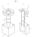
- FIG. 4 is a schematic diagram showing a specific example of the exhaust section VU.
- FIG. 4(a) is a perspective view showing the overall configuration of the exhaust section VU
- FIG. 4(b) is a partial cutaway view of the exhaust section VU.
- the exhaust section VU has a housing 12 having an internal space 13 and a piping connection section 40A, and the housing 12 and the piping connection section 40A are connected.
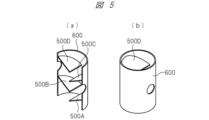
- FIG. 5 is a diagram showing a schematic of the baffle 600.
- FIG. 5(a) is a schematic diagram showing the interior of the baffle 600
- FIG. 5(b) is a schematic diagram showing the external configuration of the baffle.
- the baffle 600 has a cylindrical shape, and a plurality of capture plates 500A-500D are provided inside the baffle 600.
- Each of the plurality of capture plates 500A-500D is configured, for example, to have a sector shape.
- FIG. 6 is a partial cutaway view showing a configuration in which the baffle 600 shown in FIG. 5 is incorporated into the exhaust section VU shown in FIG. 4.
- a baffle 600 provided with multiple capture plates 500A-500D is incorporated into the internal space of the housing 12, which is a component of the exhaust section VU. This constitutes a specific example of the exhaust section VU in the embodied form.
- the first feature of the embodiment is that, for example, as shown in FIG. 3, multiple capture plates 500A-500D are provided in the internal space 13 of the housing 12.
- the first feature is that the exhaust section VU has multiple capture plates 500A-500D.
- the droplets 300 contained in the gas 200 flowing from the cylinder 10 into the exhaust section VU adhere to the capture plates 500A-500D, which prevents the droplets 300 from entering the piping 40 from the exhaust port 12B of the exhaust section VU (see FIG. 3).
- the droplets 300 are prevented from adhering to the inner wall of the piping 40 and solidifying, which causes the accumulation of foreign matter, thereby preventing blockage of the piping 40 due to the accumulation of foreign matter.
- gas 200 containing droplets 300 is generated from kneaded material 150 kneaded by rotating screws 11A and 11B provided inside cylinder 10. Then, gas 200 containing droplets 300 flows from opening OP provided in cylinder 10 into internal space 13 of housing 12, which is a component of exhaust section VU. Gas 200 containing droplets 300 that has flowed into internal space 13 first comes into contact with capture plate 500A protruding from the inner wall of internal space 13 in the first protruding direction. In other words, part of the flow of gas 200 containing droplets 300 that has flowed into internal space 13 is blocked by capture plate 500A. At this time, part of droplets 300 contained in gas 200 adheres to capture plate 500A. As a result, part of droplets 300 contained in gas 200 is removed.
- the portion of the gas 200 that was not blocked by the capture plate 500A travels upward through the internal space 13 and comes into contact with the capture plate 500B that protrudes in the second protruding direction from the inner wall of the internal space 13. This causes some of the droplets 300 contained in the gas 200 to adhere to the capture plate 500B. As a result, some of the droplets 300 contained in the gas 200 are removed.
- the portion of the gas 200 that is not blocked by the capture plate 500B travels upward through the internal space 13 and comes into contact with the capture plate 500C that protrudes from the inner wall of the internal space 13 in the first protruding direction. This causes some of the droplets 300 contained in the gas 200 to adhere to the capture plate 500C. As a result, some of the droplets 300 contained in the gas 200 are removed.
- the gas 200 from which most of the droplets 300 have been removed is exhausted from the pipe 40 through the exhaust port 12B provided on the opposing surface (top surface) of the housing 12 that faces the opening OP.
- the first characteristic point most of the droplets 300 contained in the gas 200 are removed by adhering to the capture plates 500A-500D. Therefore, according to the first characteristic point, the droplets 300 are prevented from entering the pipe 40, and as a result, clogging of the pipe 40 due to the droplets 300 can be prevented.
- the second feature of the embodiment is that, for example, as shown in FIG. 3, an exhaust port 12B is provided on the opposing surface (upper surface) of the housing 12 that faces the opening OP provided in the cylinder 10.
- an exhaust port 12B is provided on the opposing surface (upper surface) of the housing 12 that faces the opening OP provided in the cylinder 10.
- the larger the droplets 300 the greater the gravity applied to the droplets 300, making it easier for them to return from the pipe 40 to the internal space 13 of the housing 12, thereby reducing the potential for large droplets 300 that would clog the pipe 40 to adhere to the inner wall of the pipe 40.
- the second feature when combined with the first feature described above, can further prevent clogging of the pipe 40 caused by the droplets 300.
- FIG. 7 is a diagram for explaining an example of the length of the capture plate.
- the direction in which the gas containing the droplets flows into the internal space 13 of the housing 12 is the vertical direction (Y direction).
- the direction in which the gas containing the droplets flows into the internal space 13 of the housing 12 is perpendicular to the opening provided in the cylinder.
- the first protruding direction in which capture plate 500A and capture plate 500C each protrude from the inner wall of housing 12 into internal space 13 is a direction inclined from the horizontal direction (X direction)
- the second protruding direction in which capture plate 500B and capture plate 500D each protrude from the inner wall of housing 12 into internal space 13 is a direction inclined from the horizontal direction (X direction).
- the capture efficiency of the capture plates 500A-500D in capturing droplets contained in the gas can be improved.
- the length of each of the capture plates 500A-500D is designed so that the relationships 0.5 ⁇ L1/W and 0.5 ⁇ L2/W are satisfied, the probability that the gas containing droplets will come into contact with each of the capture plates 500A-500D increases, and most of the droplets contained in the gas can be removed by adhering to the capture plates 500A-500D.
- Figure 8 is a diagram explaining another example of the length of the capture plate.
- the inflow direction of the gas containing the droplets flowing into the internal space 13 of the housing 12 is the vertical direction (Y direction).
- the first protruding direction in which each of the capture plates 500A and 500C protrudes from the inner wall of the housing 12 into the internal space 13 is a direction inclined from the horizontal direction (X direction)
- the second protruding direction in which each of the capture plates 500B and 500D protrudes from the inner wall of the housing 12 into the internal space 13 is a direction inclined from the horizontal direction (X direction).
- the capture efficiency of the capture plates 500A-500D for capturing droplets contained in the gas is lower than that of the configuration shown in FIG. 7, but the passage efficiency of the gas passing through the internal space 13 can be improved.
- the gas passage efficiency can be improved, and therefore the exhaust efficiency of the gas generated from the kneaded material can be improved.
- FIG. 9 is a diagram for explaining an example of the arrangement angle of the capture plate.
- the inflow direction of the gas containing the droplets flowing into the internal space 13 of the housing 12 is the vertical direction (Y direction).
- the first protruding direction in which each of the capture plates 500A and 500C protrudes from the inner wall of the housing 12 into the internal space 13 is a direction inclined from the horizontal direction (X direction)
- the second protruding direction in which each of the capture plates 500B and 500D protrudes from the inner wall of the housing 12 into the internal space 13 is a direction inclined from the horizontal direction (X direction).
- the angle between the horizontal direction and the first protruding direction is ⁇ 1
- the angle between the horizontal direction and the second protruding direction is ⁇ 2. If ⁇ 1 and ⁇ 2 are small, the size of the housing 12 having the internal space 13 can be reduced.
- Figure 10 is a diagram illustrating another example of the capture plate placement angle.
- the inflow direction of the gas containing the droplets flowing into the internal space 13 of the housing 12 is the vertical direction (Y direction).
- the first protruding direction in which each of the capture plates 500A and 500C protrudes from the inner wall of the housing 12 into the internal space 13 is a direction inclined from the horizontal direction (X direction)
- the second protruding direction in which each of the capture plates 500B and 500D protrudes from the inner wall of the housing 12 into the internal space 13 is a direction inclined from the horizontal direction (X direction).
- the angle between the horizontal direction and the first protruding direction is ⁇ 1
- the angle between the horizontal direction and the second protruding direction is ⁇ 2.
- the capture plates 500A-500D it is desirable to arrange the capture plates 500A-500D so that the relationships 40° ⁇ 1 ⁇ 50° and 40° ⁇ 2 ⁇ 50° are satisfied.
- the basic concept can also be realized by arranging each of the capture plates 500A-500D so that they protrude horizontally (X direction) from the inner wall of the housing 12.
- FIG. 11 is a diagram showing a schematic configuration of the exhaust unit VU in the first modified example.
- one capture plate 500A is provided in the internal space 13 of the housing 12, which is a component of the exhaust section VU.
- the exhaust section VU may be configured to have one capture plate 500A. That is, the basic idea can be embodied not only as a configuration in which multiple capture plates 500A-500D are provided in the exhaust section VU, as in the embodiment shown in FIG. 3, but also as a configuration in which one capture plate 500A is provided in the exhaust section VU, as in this modified example 1 shown in FIG. 11.
- FIG. 12 is a diagram showing a schematic configuration of the exhaust unit VU in the second modified example.
- an exhaust port 12A is provided on the side of the housing 12, which is a component of the exhaust section VU.
- the exhaust section VU may be configured to provide the exhaust port 12A on the side of the housing 12. That is, the basic idea can be embodied not only as a configuration in which the housing 12 has an exhaust port 12B on the top surface, as in the embodiment shown in FIG. 3, but also as a configuration in which the housing 12 has an exhaust port 12A on the side, as in this modified example 2 shown in FIG. 12.
Landscapes
- Engineering & Computer Science (AREA)
- Mechanical Engineering (AREA)
- Extrusion Moulding Of Plastics Or The Like (AREA)
- Separating Particles In Gases By Inertia (AREA)
- Separation Of Particles Using Liquids (AREA)
- Treating Waste Gases (AREA)
Priority Applications (5)
| Application Number | Priority Date | Filing Date | Title |
|---|---|---|---|
| PCT/JP2022/045342 WO2024122033A1 (ja) | 2022-12-08 | 2022-12-08 | 押出機および排気用筐体 |
| JP2024562526A JPWO2024122033A1 (https=) | 2022-12-08 | 2022-12-08 | |
| EP22967879.2A EP4631708A1 (en) | 2022-12-08 | 2022-12-08 | Extruder and housing for exhaust air |
| CN202280102254.7A CN120282877A (zh) | 2022-12-08 | 2022-12-08 | 挤出机及排气用框体 |
| TW112131895A TW202423661A (zh) | 2022-12-08 | 2023-08-24 | 擠出機及排氣用箱體 |
Applications Claiming Priority (1)
| Application Number | Priority Date | Filing Date | Title |
|---|---|---|---|
| PCT/JP2022/045342 WO2024122033A1 (ja) | 2022-12-08 | 2022-12-08 | 押出機および排気用筐体 |
Publications (1)
| Publication Number | Publication Date |
|---|---|
| WO2024122033A1 true WO2024122033A1 (ja) | 2024-06-13 |
Family
ID=91379070
Family Applications (1)
| Application Number | Title | Priority Date | Filing Date |
|---|---|---|---|
| PCT/JP2022/045342 Ceased WO2024122033A1 (ja) | 2022-12-08 | 2022-12-08 | 押出機および排気用筐体 |
Country Status (5)
| Country | Link |
|---|---|
| EP (1) | EP4631708A1 (https=) |
| JP (1) | JPWO2024122033A1 (https=) |
| CN (1) | CN120282877A (https=) |
| TW (1) | TW202423661A (https=) |
| WO (1) | WO2024122033A1 (https=) |
Cited By (1)
| Publication number | Priority date | Publication date | Assignee | Title |
|---|---|---|---|---|
| CN118636408A (zh) * | 2024-07-23 | 2024-09-13 | 宁波天汇汽车零部件有限公司 | 注塑机用注射装置及注塑机 |
Citations (4)
| Publication number | Priority date | Publication date | Assignee | Title |
|---|---|---|---|---|
| JPS60179407U (ja) * | 1984-05-11 | 1985-11-28 | 森山 正夫 | 押出機等のガス抜き装置 |
| JPH10309555A (ja) * | 1997-05-08 | 1998-11-24 | Toshiba Corp | 廃棄物処理装置 |
| JP2020040012A (ja) * | 2018-09-10 | 2020-03-19 | 株式会社Azuma | 液切板及びそれを備える湿式集塵機 |
| WO2022091492A1 (ja) * | 2020-10-29 | 2022-05-05 | 株式会社日本製鋼所 | 炭素系燃料の製造方法および炭素系燃料の製造装置 |
-
2022
- 2022-12-08 CN CN202280102254.7A patent/CN120282877A/zh active Pending
- 2022-12-08 WO PCT/JP2022/045342 patent/WO2024122033A1/ja not_active Ceased
- 2022-12-08 JP JP2024562526A patent/JPWO2024122033A1/ja active Pending
- 2022-12-08 EP EP22967879.2A patent/EP4631708A1/en active Pending
-
2023
- 2023-08-24 TW TW112131895A patent/TW202423661A/zh unknown
Patent Citations (5)
| Publication number | Priority date | Publication date | Assignee | Title |
|---|---|---|---|---|
| JPS60179407U (ja) * | 1984-05-11 | 1985-11-28 | 森山 正夫 | 押出機等のガス抜き装置 |
| JPH10309555A (ja) * | 1997-05-08 | 1998-11-24 | Toshiba Corp | 廃棄物処理装置 |
| JP2020040012A (ja) * | 2018-09-10 | 2020-03-19 | 株式会社Azuma | 液切板及びそれを備える湿式集塵機 |
| WO2022091492A1 (ja) * | 2020-10-29 | 2022-05-05 | 株式会社日本製鋼所 | 炭素系燃料の製造方法および炭素系燃料の製造装置 |
| JP2022071945A (ja) | 2020-10-29 | 2022-05-17 | 株式会社日本製鋼所 | 炭素系燃料の製造方法および炭素系燃料の製造装置 |
Non-Patent Citations (1)
| Title |
|---|
| See also references of EP4631708A1 |
Cited By (2)
| Publication number | Priority date | Publication date | Assignee | Title |
|---|---|---|---|---|
| CN118636408A (zh) * | 2024-07-23 | 2024-09-13 | 宁波天汇汽车零部件有限公司 | 注塑机用注射装置及注塑机 |
| CN118636408B (zh) * | 2024-07-23 | 2025-01-14 | 宁波天汇汽车零部件有限公司 | 注塑机用注射装置及注塑机 |
Also Published As
| Publication number | Publication date |
|---|---|
| CN120282877A (zh) | 2025-07-08 |
| TW202423661A (zh) | 2024-06-16 |
| EP4631708A1 (en) | 2025-10-15 |
| JPWO2024122033A1 (https=) | 2024-06-13 |
Similar Documents
| Publication | Publication Date | Title |
|---|---|---|
| WO2024122033A1 (ja) | 押出機および排気用筐体 | |
| CN1923459A (zh) | 具有冷却液过滤装置的切屑输送机 | |
| CN210546252U (zh) | 一种水利工程用筛选装置 | |
| WO2024012401A1 (zh) | 用于3d打印机的废料排出装置以及3d打印机 | |
| US10029636B2 (en) | Radiator screen device, radiator screen unit, and industrial vehicle | |
| JP6348406B2 (ja) | 第1流体の粒子であって、第2流体の流れに載った第1流体の粒子を第2流体の流れから分離し、第1流体は、第2流体よりも濃度が高い分離システム | |
| JP2000071474A (ja) | 気液分離チャンバーおよびこれを具備するインクジェットプリンタ | |
| JP3790852B2 (ja) | 空気洗浄装置 | |
| JP5198589B2 (ja) | 濾過装置 | |
| CN118594139A (zh) | 一种用于烟气处理中的气固分离器 | |
| JPH10198460A (ja) | 電子筐体の防塵システム | |
| CN116163823A (zh) | 一种用于滤清器的过滤结构及滤清器 | |
| JP3166971U (ja) | 濾過装置 | |
| CN107234066B (zh) | 回转组合多层筛的二次抽风进料系统 | |
| CN220617658U (zh) | 散粉分流输送装置 | |
| CN219130680U (zh) | 一种消失模铸造用晾砂装置 | |
| CN219597290U (zh) | 一种除尘筛分设备及除尘筛分系统 | |
| CN220715210U (zh) | 活性碳废气吸附设备 | |
| CN207576882U (zh) | 一种大米分级筛 | |
| CN111891779A (zh) | 一种颗粒储用的出料机构 | |
| CN222788742U (zh) | 一种复合平板式过滤器 | |
| CN214358630U (zh) | 一种输料用除尘装置 | |
| CN222151033U (zh) | 渣石分离采集装置 | |
| CN111821791B (zh) | 过滤装置 | |
| JP3382238B2 (ja) | ロータリーバルブ |
Legal Events
| Date | Code | Title | Description |
|---|---|---|---|
| 121 | Ep: the epo has been informed by wipo that ep was designated in this application |
Ref document number: 22967879 Country of ref document: EP Kind code of ref document: A1 |
|
| WWE | Wipo information: entry into national phase |
Ref document number: 2024562526 Country of ref document: JP |
|
| WWE | Wipo information: entry into national phase |
Ref document number: 202517050754 Country of ref document: IN |
|
| WWE | Wipo information: entry into national phase |
Ref document number: 202280102254.7 Country of ref document: CN |
|
| WWP | Wipo information: published in national office |
Ref document number: 202517050754 Country of ref document: IN |
|
| WWE | Wipo information: entry into national phase |
Ref document number: 2022967879 Country of ref document: EP |
|
| WWP | Wipo information: published in national office |
Ref document number: 202280102254.7 Country of ref document: CN |
|
| NENP | Non-entry into the national phase |
Ref country code: DE |
|
| ENP | Entry into the national phase |
Ref document number: 2022967879 Country of ref document: EP Effective date: 20250708 |
|
| WWP | Wipo information: published in national office |
Ref document number: 2022967879 Country of ref document: EP |