WO2024121957A1 - 生体検知装置、電波センサ、生体検知システム、および、生体検知方法 - Google Patents
生体検知装置、電波センサ、生体検知システム、および、生体検知方法 Download PDFInfo
- Publication number
- WO2024121957A1 WO2024121957A1 PCT/JP2022/045008 JP2022045008W WO2024121957A1 WO 2024121957 A1 WO2024121957 A1 WO 2024121957A1 JP 2022045008 W JP2022045008 W JP 2022045008W WO 2024121957 A1 WO2024121957 A1 WO 2024121957A1
- Authority
- WO
- WIPO (PCT)
- Prior art keywords
- radio wave
- living body
- distance
- seat
- sensor
- Prior art date
- Legal status (The legal status is an assumption and is not a legal conclusion. Google has not performed a legal analysis and makes no representation as to the accuracy of the status listed.)
- Ceased
Links
Images




Classifications
-
- G—PHYSICS
- G01—MEASURING; TESTING
- G01S—RADIO DIRECTION-FINDING; RADIO NAVIGATION; DETERMINING DISTANCE OR VELOCITY BY USE OF RADIO WAVES; LOCATING OR PRESENCE-DETECTING BY USE OF THE REFLECTION OR RERADIATION OF RADIO WAVES; ANALOGOUS ARRANGEMENTS USING OTHER WAVES
- G01S13/00—Systems using the reflection or reradiation of radio waves, e.g. radar systems; Analogous systems using reflection or reradiation of waves whose nature or wavelength is irrelevant or unspecified
- G01S13/02—Systems using reflection of radio waves, e.g. primary radar systems; Analogous systems
- G01S13/06—Systems determining position data of a target
- G01S13/08—Systems for measuring distance only
- G01S13/32—Systems for measuring distance only using transmission of continuous waves, whether amplitude-, frequency-, or phase-modulated, or unmodulated
- G01S13/34—Systems for measuring distance only using transmission of continuous waves, whether amplitude-, frequency-, or phase-modulated, or unmodulated using transmission of continuous, frequency-modulated waves while heterodyning the received signal, or a signal derived therefrom, with a locally-generated signal related to the contemporaneously transmitted signal
-
- G—PHYSICS
- G01—MEASURING; TESTING
- G01S—RADIO DIRECTION-FINDING; RADIO NAVIGATION; DETERMINING DISTANCE OR VELOCITY BY USE OF RADIO WAVES; LOCATING OR PRESENCE-DETECTING BY USE OF THE REFLECTION OR RERADIATION OF RADIO WAVES; ANALOGOUS ARRANGEMENTS USING OTHER WAVES
- G01S13/00—Systems using the reflection or reradiation of radio waves, e.g. radar systems; Analogous systems using reflection or reradiation of waves whose nature or wavelength is irrelevant or unspecified
- G01S13/02—Systems using reflection of radio waves, e.g. primary radar systems; Analogous systems
- G01S13/50—Systems of measurement based on relative movement of target
- G01S13/52—Discriminating between fixed and moving objects or between objects moving at different speeds
- G01S13/56—Discriminating between fixed and moving objects or between objects moving at different speeds for presence detection
Definitions
- This disclosure relates to a biological detection device, a radio wave sensor, a biological detection system, and a biological detection method.
- Patent Document 1 discloses a technology for detecting a living body present in a vehicle cabin based on information contained in the received reflected waves by a radio wave sensor that is installed in the vehicle cabin, radiates radio waves into the vehicle cabin, and receives reflected waves of the radiated radio waves reflected by the body surface (for example, Patent Document 1).
- radio waves emitted from a radio wave sensor When radio waves emitted from a radio wave sensor are irradiated onto a structure or the like in a room, the irradiated radio waves are reflected depending on the material of the structure or the like. For example, if a living body is present in a blind spot from the radio wave sensor, such as a place indoors that is blocked by a structure that reflects the emitted radio waves, the radio waves emitted from the radio wave sensor may not be directly reflected by the surface of the living body. The conventional technology does not take this into consideration, and therefore there is still a problem that it may not be possible to detect a living body present in the room.
- This disclosure has been made to solve the problems described above, and aims to provide a living body detection device that can detect living bodies present in a room.
- the living body detection device includes a sensor information acquisition unit that acquires sensor information generated based on reflected waves of radio waves emitted by a radio wave sensor toward an indoor area including at least a seat present in the room and reflected by an object in the room, and a detection unit that detects whether or not a living body is present in the room based on the sensor information acquired by the sensor information acquisition unit, a first distance from the position of the radio wave sensor to a first target point that is a point on the top surface of a columnar target area having a height in the height direction of the seat that is a target for detecting the presence or absence of a living body based on the sensor information, and is the closest point to the position of the radio wave sensor, a second distance from the position of the radio wave sensor to a second target point that is a point on the top surface of the target area and is the farthest point from the position of the radio wave sensor compared to the first target point, and a third distance from the second target point to a third target point that is the
- FIG. 4 is a diagram showing a radio wave sensor function equipped with the living body detection device according to the first embodiment.
- FIG. 1 is a diagram illustrating a configuration example of a biological detection device according to a first embodiment
- 3A to 3C are diagrams for explaining an example of installation of a radio wave sensor and radio waves radiated from the radio wave sensor in the first embodiment.
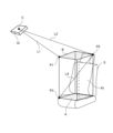
- 4 is a diagram showing an example of a target region set by a region setting unit in the first embodiment
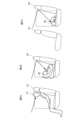
- FIG. Figures 5A, 5B, and 5C are diagrams illustrating an example in which, in embodiment 1, the detection unit detects whether or not a living body is present in the vehicle cabin based on whether or not the distance to an object detected by the radio wave sensor satisfies the first detection condition.
- FIG. 4 is a flowchart for explaining an operation of the biological detection device according to the first embodiment.
- 4 is a diagram for explaining an example of how the radiation range of radio waves radiated from a transmission antenna is controlled by a radio wave sensor in the first embodiment.
- FIG. 1 is a diagram showing an example of the configuration of a living body detection system including a radio wave sensor and a living body detection device in a first embodiment;
- 10A and 10B are diagrams illustrating an example of a hardware configuration of a biological detection device according to the first embodiment.
- the living body detection device detects whether or not a living body is present in a room based on sensor information generated by a radio wave sensor.
- the radio wave sensor emits radio waves toward an area within a room that includes at least the seats present in the room (hereinafter referred to as the "indoor area"), receives reflected waves of the radio waves, detects objects present in the room based on the reflected waves, and generates sensor information.
- the seat is assumed to have a backrest.
- the interior of the vehicle is assumed to be the interior of the vehicle.
- the radio wave sensor is installed in the vehicle interior, emits radio waves toward an interior area including at least the front seats or the rear seats in the vehicle interior, receives reflected waves of the radio waves, detects objects in the vehicle interior, and generates sensor information.
- Including the front seats or the rear seats specifically means an area above the seat surface of the front seats and in front of the backrest of the front seats including the headrests, or an area above the seat surface of the rear seats and in front of the backrest of the rear seats including the headrests.
- the living body detection device detects whether or not an occupant is present in the vehicle cabin based on the sensor information generated by the radio wave sensor.
- a “rear seat” refers to a seat that has a seat in front of it.
- a “front seat” refers to a seat that does not have a seat in front of it. For example, if a vehicle has three rows of seats, then the vehicle has two rows of rear seats.
- the living organisms detected by the living organism detection device include various living organisms such as pets, in addition to humans.
- the living organism detection device detects humans who are occupants of a vehicle.
- the occupants of a vehicle include infants and young children seated in child seats.
- the biological detection device 1 according to the first embodiment is mounted on a radio wave sensor 10, for example.
- FIG. 1 is a diagram showing functions of a radio wave sensor 10 equipped with a living body detection device 1 according to the first embodiment.
- FIG. 2 is a diagram showing an example of the configuration of the living body detection device 1 according to the first embodiment.
- the radio wave sensor 10 is mounted on a vehicle (not shown).
- the radio wave sensor 10 is assumed to be a millimeter wave radar.
- the living body detection device 1 detects whether or not an occupant is present in the vehicle cabin based on sensor information generated by the radio wave sensor 10.
- the living body detection device 1 is connected to the abandoned body detection device 200, and outputs a detection result of whether or not an occupant is present in the vehicle cabin to the abandoned body detection device 200.
- the abandoned body detection device 200 is mounted on, for example, a vehicle, and outputs an alarm based on the detection result of whether or not an occupant is present in the vehicle cabin output from the living body detection device 1.
- the abandoned body detection device 200 may be provided in a location outside the vehicle that can be accessed by the living body detection device 1, such as a server (not shown) outside the vehicle.
- FIG. 3 is a diagram for explaining an example of installation of the radio wave sensor 10 and radio waves radiated from the radio wave sensor 10 in the first embodiment.
- the vehicle is indicated by "100”
- the front seat is indicated by “S1”
- the rear seat is indicated by “S2”
- Fig. 3 is a view of the vehicle seen from the side.
- a forward-facing child seat (indicated by "CH” in Fig. 3) is installed in the rear seat of the vehicle interior, and an infant (indicated by "H” in Fig. 3) is placed in the child seat.
- the vehicle is a left-hand drive vehicle, but this is merely an example, and the vehicle may be a right-hand drive vehicle.
- the radio wave sensor 10 is installed, for example, in an overhead console of the vehicle, radiates radio waves toward the interior of the vehicle cabin, and receives the waves reflected by objects within the vehicle cabin.
- the radio waves emitted from the radio wave sensor 10 installed in the overhead console reach the area in the vehicle interior in front of the backrest of the front seat directly, but do not reach the area in the vehicle interior in front of the backrest of the rear seat directly because the front seat acts as a shield. In other words, the radio wave sensor 10 cannot see into the area in the vehicle interior in front of the backrest of the rear seat.
- the radio waves emitted from the radio wave sensor 10 reach the area in the vehicle interior in front of the backrest of the rear seat after being reflected by structures in the vehicle interior such as the ceiling or the headrest of the seat (hereinafter referred to as "vehicle interior structures").
- vehicle interior structures structures in the vehicle interior such as the ceiling or the headrest of the seat
- the radio waves emitted from the radio wave sensor 10 are not directly irradiated to the occupant (here, an infant), but are irradiated to the occupant after being reflected by structures in the vehicle interior.
- the living body detection device 1 of embodiment 1 is thus capable of detecting occupants in the vehicle cabin by taking advantage of the phenomenon in which radio waves from the radio wave sensor 10 are reflected by interior structures, etc. and irradiated to the occupants, even if the radio waves emitted from the radio wave sensor 10 are not directly irradiated to the occupants, in other words, even if the radio wave sensor 10 cannot directly see the occupants.
- FIG. 3 does not show an occupant sitting in the front seat, but even in the area of the vehicle interior in front of the front seat, the radio waves emitted from the radio wave sensor 10 do not necessarily reach the occupant sitting in the front seat directly.
- the child seat may act as a shield and the radio waves emitted from the radio wave sensor 10 may not be directly irradiated to the infant.
- the radio waves from the radio wave sensor 10 will be reflected by structures in the vehicle interior before reaching the infant.
- the living body detection device 1 is able to detect an occupant in the vehicle interior even in such a case by utilizing the phenomenon in which the radio waves from the radio wave sensor 10 are reflected by structures in the vehicle interior and irradiated to the occupant.
- the interior area of the vehicle is the entire space within the vehicle, and as shown in FIG. 3, it is assumed that the radio wave sensor 10 is installed in the overhead console of the vehicle.
- the interior area of the vehicle may be, for example, an area within the vehicle interior that does not include the front seats but includes the rear seats.
- the radio wave sensor 10 is not limited to being installed in the overhead console of the vehicle.
- the radio wave sensor 10 may be installed on the ceiling of the vehicle interior or on the dashboard. It is sufficient that the radio wave sensor 10 is installed so as to be able to irradiate radio waves toward the interior area of the vehicle.
- the transmitting antenna Tx is a planar antenna configured on an electronic circuit board.
- the transmitting antenna Tx has one or more transmitting antenna elements that radiate radio waves toward the interior area of the vehicle cabin.
- the installation positions of each transmitting antenna element are different from each other in the vehicle height direction.
- the receiving antenna Rx is a planar antenna configured on an electronic circuit board, and is installed on the same plane as the transmitting antenna Tx.
- the same plane here does not mean that the plane on which the transmitting antenna Tx is installed is strictly the same as the plane on which the receiving antenna Rx is installed, and includes different planes as long as there are no practical problems.
- the receiving antenna Rx has one or more receiving antenna elements that receive the reflected wave of the radio wave radiated from the transmitting antenna Tx.
- the installation positions of each receiving antenna element are different from each other in the vehicle width direction.
- the radio wave sensor circuit section 13 includes a high frequency signal generating circuit 14, a radio wave transmitting section 15, a radio wave receiving section 16, an analog-to-digital conversion circuit (hereinafter referred to as "A/D conversion circuit") 17, a signal processing section 18, and the living body detection device 1.
- the high frequency signal generating circuit 14, the radio wave transmitting section 15, and the radio wave receiving section 16 constitute a radio wave transmitting/receiving section 19 that radiates radio waves from the transmitting antenna Tx and obtains a received signal based on the reflected waves from the receiving antenna Rx.
- the high frequency signal generating circuit 14 generates an FM (Frequency Modulation) signal, the frequency of which changes over time, as a sensing signal, and outputs the FM signal to both the radio wave transmitting unit 15 and the radio wave receiving unit 16 .
- FM-CW Frequency Modulation-Continuous Wave
- the modulation method is not limited to FM-CW, and for example, FCM (Fast-Chirp Modulation) may be used.
- FCM Frest-Chirp Modulation
- the high frequency signal generating circuit 14 When the FCM method is used as the modulation method, the high frequency signal generating circuit 14 generates an FCM signal and outputs the FCM signal to each of the radio wave transmitting unit 15 and the radio wave receiving unit 16.
- the radio wave transmitting section 15 includes a transmitting circuit 15-1.
- the radio wave transmitting unit 15 radiates radio waves from the transmitting antenna element toward the vehicle interior area.
- the radio wave transmitting unit 15 radiates radio waves from, for example, any one of the multiple transmitting antenna elements toward the vehicle interior area. That is, the radio wave transmitting unit 15 sequentially switches one transmitting antenna element from among the multiple transmitting antenna elements to radiate radio waves.
- the radio wave transmitting unit 15 may radiate radio waves from, for example, multiple transmitting antenna elements toward the vehicle interior area at the same time.
- the radio wave transmitting unit 15 can distinguish which transmitting antenna element a signal is transmitted from by using a known method such as encoding.
- the radio wave transmitting section 15 causes the transmitting antenna element to radiate radio waves, it causes the transmitting circuit 15-1 to output an FM signal to the transmitting antenna element.
- the transmission circuit 15-1 amplifies the FM signal output from the high frequency signal generating circuit 14 and outputs the amplified FM signal to the transmission antenna element, causing the transmission antenna element to radiate FM transmission waves, which are radio waves, toward the interior area of the vehicle cabin.
- the radio wave receiving section 16 includes a receiving circuit 16-1.
- the reception circuit 16-1 acquires a reception signal of the FM reception wave from the reception antenna element.
- the receiving circuit 16-1 extracts the difference fd between the frequency of the FM signal output from the high frequency signal generating circuit 14 and the frequency of the received signal (hereinafter referred to as the "frequency difference").
- the receiving circuit 16 - 1 generates an intermediate frequency signal IF having a frequency difference fd , and outputs the intermediate frequency signal IF to the A/D conversion circuit 17 .
- FIG. 1 only one each of the transmitting antenna Tx, receiving antenna Rx, transmitting circuit 15-1, and receiving circuit 16-1 is shown, but the configuration may include multiple transmitting antennas Tx, receiving antennas Rx, transmitting circuits 15-1, and receiving circuits 16-1.
- the A/D conversion circuit 17 converts the intermediate frequency signal IF output from the receiving circuit 16-1 from an analog signal to a digital signal D.
- the A/D conversion circuit 17 outputs a digital signal D to a signal processing unit 18 .
- the signal processing unit 18 is realized by, for example, a digital signal processing circuit.
- the signal processing unit 18 obtains from the A/D conversion circuit 17 a digital signal D related to the FM reception wave received by the reception circuit 16-1.
- the signal processing unit 18 detects an object present within the vehicle interior based on the digital signal D.
- the signal processing unit 18 determines the position of the detected object, in other words, the distance and angle to the object, based on the digital signal D.
- the signal processing unit 18 determines the relative speed of the detected object based on the digital signal D.
- the signal processing unit 18 identifies the signal intensity of the reflected wave that is the emitted wave reflected by the object.
- the signal processing unit 18 generates sensor information, which includes reflected power information indicating the signal strength of the reflected wave, speed information indicating the speed of the detected object, and position information indicating the position (distance and angle) of the detected object.
- the signal processing unit 18 may apply an MTI (Moving Target Indicators) filter to suppress reflections from vehicle structures such as seats (front seats or rear seats), doors, or the ceiling, and then perform frequency analysis on the suppressed digital signal D, and then identify the distance and angle to the object, the relative speed of the object, and the signal strength of the reflected wave to generate sensor information.
- the signal processing unit 18 outputs the generated sensor information to the living body detection device 1 .
- the digital signal processing circuitry may be implemented, for example, by a single circuit, a composite circuit, a programmed processor, a parallel programmed processor, an ASIC (Application Specific Integrated Circuit), an FPGA (Field-Programmable Gate Array), or a combination thereof.
- the digital signal processing circuit is not limited to being realized by dedicated hardware, but may be realized by software, firmware, or a combination of software and firmware.
- the software or firmware is stored as a program in the memory of a computer.
- the computer means hardware that executes the program, and includes, for example, a CPU (Central Processing Unit), a central processing unit, a processing unit, an arithmetic unit, a microprocessor, a microcomputer, a processor, or a DSP (Digital Signal Processor).
- the biological detection device 1 includes a sensor information acquisition unit 101, a region setting unit 102, a distance calculation unit 103, a detection unit 104, and an output unit 105, as shown in the configuration example of FIG.
- the sensor information acquisition unit 101 acquires sensor information from the signal processing unit 18 .
- the sensor information acquisition unit 101 outputs the acquired sensor information to the area setting unit 102 .
- the area setting unit 102 performs a "target area setting process" to set an object area within the vehicle cabin and to set a first object point, a second object point, and a third object point.
- the target area refers to a columnar area within the vehicle cabin having a height in the height direction of the seats (front seats or rear seats) that is the target for the living body detection device 1 to detect the presence or absence of a living body based on sensor information.
- the area setting unit 102 sets a target area for each seat in the vehicle cabin. The first target point, the second target point, and the third target point will be described later. First, the setting of the target region by the region setting unit 102 will be described.
- FIG. 4 is a diagram showing an example of a target region set by region setting unit 102 in the first embodiment.
- FIG. 4 illustrates only the radio wave sensor 10 and one seat. 4, "S" indicates a seat, and "C” indicates the position of the radio wave sensor 10.
- the position of the radio wave sensor 10 is represented by the installation position of the radio wave transmitter 15 of the radio wave sensor 10, for example.
- the region of interest is indicated as "R1.”
- the region setting unit 102 sets, for example, a columnar region having a height of the seat backrest, in the vehicle interior region, with a surface including the seat surface of a square or rectangular seat (hereinafter referred to as the "seat surface upper surface") as the bottom surface and the seat surface upper surface moved to the top end of the seat backrest as the top surface, as the target region.
- the seat surface upper surface is, for example, a square or rectangular virtual surface having the four corners of the seat surface as its four corners.
- the headrest is included in the backrest.
- the region setting unit 102 sets the target region as a columnar region having the top surface of the seat as its bottom surface, the top surface of the seat when moved to the top end of the headrest of the seat as its top surface, and the height up to the top end of the headrest.
- the region setting unit 102 sets the region through which the upper surface of the seat passes when the upper surface of the seat is translated to the height of the upper end of the headrest as the target region.
- the target region is a region having a shape of a rectangular prism with the upper surface of the seat (see “A” in Fig. 4) as its bottom surface and the upper surface of the seat when it is in a position translated to the height of the upper end of the headrest (see “B” in Fig. 4) as its top surface.
- the target area shown in FIG. 4 is merely an example, and the area setting unit 102 may set an area having a shape other than that shown in FIG. 4 as the target area.
- the area setting unit 102 may set a columnar area in the vehicle interior area, whose base is a surface in front of the seat back that includes at least the upper surface of the seat, and whose height reaches the top end of the seat back, as the target area.
- the target area may be an area having a cylindrical shape or an area having a pentagonal prism shape.
- the area setting unit 102 sets the target area, it sets the following first target point, second target point, and third target point.
- the first target point is a point on the top surface of the target area and is located closest to the position of the radio wave sensor 10 (indicated as "P1" in FIG. 4). Note that in the first embodiment, "closest to the position of the radio wave sensor 10" is not limited to being strictly closest, but includes being close to the position of the radio wave sensor 10 within the margin of error. When there are multiple first target points, the distance calculation unit 103 may select any one of the points as the first target point.
- the second target point is a point on the top surface of the target area, and is located farthest from the position of the radio wave sensor 10 compared to the first target point (shown as "P2" in FIG. 4).
- the second target point is the point on the top surface of the target area that is located farthest from the position of the radio wave sensor 10.
- "farthest from the position of the radio wave sensor 10" is not limited to being strictly the farthest, but includes being farthest from the position of the radio wave sensor 10 within the margin of error.
- the distance calculation unit 103 may select any one of the points as the second target point.
- the third target point is the point in the target region that is the farthest from the second target point (indicated as "P3" in FIG. 4). Note that in the first embodiment, “farthest from the second target point” is not limited to being strictly the farthest, but also includes being farthest from the second target point within the margin of error.
- the region setting unit 102 outputs information on the set target region, the first target point, the second target point, and the third target point (hereinafter referred to as "target region information") to the distance calculation unit 103.
- the region setting unit 102 outputs the sensor information acquired from the sensor information acquisition unit 101 to the distance calculation unit 103 together with the target region information.
- the target area information is information that can identify the position and size of the target area in the real space inside the vehicle cabin, and includes coordinates of the first target point, the second target point, and the third target point in the real space inside the vehicle cabin.
- the target area information includes the center and radius of the bottom surface of the target area and the center and radius of the top surface of the target area.
- the target area information may include the coordinates of an end of the bottom surface of the target area and the coordinates of an end of the top surface of the target area.
- the real space inside the vehicle cabin is represented by three-dimensional coordinate axes, for example, with the x-axis being an axis parallel to the vehicle width direction, the y-axis being an axis parallel to the vehicle height direction, and the z-axis being an axis parallel to the vehicle length direction. Since the position of the seat in the real space inside the vehicle cabin, the size of the seat, the height of the backrest including the headrest, etc. are known in advance, the area setting unit 102 can calculate each coordinate in the real space inside the vehicle cabin that can identify the target area.
- the area setting unit 102 may, for example, obtain information regarding the current tilt of the seat back and the fore-aft position of the seat from a seat sensor (not shown) installed in the vehicle, and set a target area and calculate the coordinates including the first target point, the second target point, and the third target point in the real space in the vehicle cabin where the target area can be identified. This allows the area setting unit 102 to set a target area that better reflects the current seat state and calculate the coordinates of the first target point, the second target point, and the third target point.
- the region setting unit 102 sets the target region as a region in the shape of a rectangular prism, as shown in FIG. 4.
- the region setting unit 102 generates information including the coordinates of the ends of the bottom surface of the target region, i.e., the coordinates of the four corners of the bottom surface of the target region, and the coordinates of the ends of the top surface of the target region, i.e., the coordinates of the four corners of the top surface of the target region, as the target region information, and outputs the information to the distance calculation unit 103.
- the region setting unit 102 assigns information that can be determined to be the coordinates of the first target point or the second target point among the coordinates of the four corners of the top surface of the target region to the coordinates of the first target point or the second target point.
- the region setting unit 102 assigns information that can be determined to be the coordinates of the third target point among the coordinates of the four corners of the bottom surface of the target region to the coordinates of the third target point.
- the region setting unit 102 may include, for example, information indicating the height of the target region in the target region information.
- the distance calculation unit 103 calculates the following first distance, second distance, and third distance from the position of the radio wave sensor 10 and the target area set by the area setting unit 102.
- the first distance is the distance from the position of the radio wave sensor 10 to the first target point.
- the first distance is indicated by "L1" in FIG.
- the second distance is the distance from the position of the radio wave sensor 10 to the second target point.
- the second distance is indicated by "L2" in FIG.
- the third distance is the distance from the second object point to the third object point and is indicated by "L3" in FIG.
- the first target point is point P1 shown in FIG. 4
- the second target point is point P2 shown in FIG. 4
- the third target point is point P3 shown in FIG.
- the distance calculation unit 103 calculates the distance from the position of the radio wave sensor 10 (position "C" in Figure 4) to point P1 as a first distance, calculates the distance from the position of the radio wave sensor 10 to point P2 as a second distance, and calculates the distance from point P2 to point P3 as a third distance.
- the position of the radio wave sensor 10 is known in advance, and the positions of points P1 to P3 are known from the target area information.
- the distance calculation unit 103 outputs information on the calculated first distance, second distance, and third distance (hereinafter referred to as "target distance information") to the detection unit 104. At this time, the distance calculation unit 103 outputs the sensor information output from the area setting unit 102 to the detection unit 104 together with the target distance information.
- the detection unit 104 detects whether or not an occupant is present in the vehicle cabin based on the sensor information acquired by the sensor information acquisition unit 101 and the first distance, the second distance, and the third distance calculated by the distance calculation unit 103.
- the distance calculation unit 103 can determine the first distance, the second distance, and the third distance from the target distance information output from the distance calculation unit 103.
- the detection unit 104 detects whether or not an occupant is present for each seat.
- the range of which spaces in the vehicle cabin correspond to each seat in the vehicle cabin is determined in advance.
- the detection unit 104 can, for example, determine from the position information included in the sensor information which the space corresponding to which seat the distance to the detected object was detected from.
- the signal processing unit 18 can determine the seat from which the distance to the object was detected depending on which transmitted wave the received wave obtained in response to which the distance is based, and associate information indicating the identified seat with the position information.
- the detection unit 104 can determine from the information indicating the seat associated with the position information which the space corresponding to which seat the distance indicated by the position information included in the sensor information was detected from.
- the detection unit 104 detects that an occupant is present in the vehicle cabin.
- the detection unit 104 can ascertain the distance to an object detected by the radio wave sensor 10 from the position information included in the sensor information.
- ⁇ First detection condition> "The distance to the object detected by the radio wave sensor 10 is equal to or greater than the first distance and equal to or less than the sum of the second distance and the third distance (hereinafter referred to as the "fourth distance").”
- the detection unit 104 detects that an occupant is present in the vehicle cabin when the distance to an object detected by the radio wave sensor 10 satisfies the first detection condition, in other words, when the distance to an object detected by the radio wave sensor 10 is greater than or equal to the first distance and less than or equal to the fourth distance.
- the detection unit 104 detects that there is no occupant in the vehicle cabin if the distance to the object detected by the radio wave sensor 10 does not satisfy the first detection condition, in other words, if the distance to the object detected by the radio wave sensor 10 is not greater than the first distance or less than the fourth distance, i.e., if the distance to the object detected by the radio wave sensor 10 is less than the first distance or greater than the fourth distance.
- FIGS. 5A, 5B, and 5C are diagrams illustrating an example in which, in embodiment 1, the detection unit 104 detects whether or not a living body is present in the vehicle cabin based on whether or not the distance to an object detected by the radio wave sensor 10 satisfies the first detection condition.
- 5A, 5B, and 5C are views of the vehicle as seen from the side, and for convenience, only the front seat or rear seat and occupants seated in the front seat or rear seat are illustrated in FIGS. 5A, 5B, and 5C.
- the front seats are designated "S1"
- in Figure 5C the rear seats are designated "S2".
- 5A, 5B, and 5C the arrows indicate images of radio waves emitted from the radio wave sensor 10.
- 5A, 5B and 5C the dotted lines indicate the regions of interest.
- FIG. 5A shows an example of the interior of a vehicle with an adult (indicated by "H1" in FIG. 5A) sitting upright in the front seat.
- Fig. 5B shows an example of the state of the interior of a vehicle with an infant (indicated by "H2" in Fig. 5B) seated in a rear-facing child seat in the front seat. Note that in the first embodiment, an occupant seated includes an infant in a child seat.
- FIG. 5C shows an example of the state inside a vehicle cabin where a child (indicated by "H3" in FIG. 5C) is lying down in the back seat.
- an occupant is sitting upright in the front seat where radio waves from the radio wave sensor 10 are irradiated to an area inside the vehicle cabin in front of the seat back.
- the radio waves irradiated from the radio wave sensor 10 reach the occupant directly.
- the radio wave sensor 10 can directly see the occupant.
- the distance to the object (i.e., the occupant) detected by the radio wave sensor 10 is assumed to be equal to or greater than the first distance and equal to or less than the fourth distance in the target area set in the front seat.
- the detection unit 104 determines whether the distance to the object detected by the radio wave sensor 10 satisfies a first detection condition, and detects that an occupant is present in the vehicle cabin if the distance to the object satisfies the first detection condition, thereby detecting the presence of an occupant in the vehicle cabin.
- an occupant is seated in the front seat, as in the example shown in Fig. 5A, but whereas in the example shown in Fig. 5A an adult is seated in a straight position, in the example shown in Fig. 5B an infant is seated in a rear-facing child seat.
- the child seat acts as a shield, and the radio waves from the radio wave sensor 10 do not directly reach the occupant. In other words, the radio wave sensor 10 cannot directly see the occupant. However, the radio waves from the radio wave sensor 10 are reflected, for example, by the backrest of the front seat and irradiated to the occupant.
- the distance from the radio wave sensor 10 to the occupant via the backrest of the front seat is assumed to be equal to or greater than the first distance and equal to or less than the fourth distance in the target area set for the front seat. Since the radio waves from the radio wave sensor 10 do not reach the occupant directly, but are reflected by the backrest of the front seat and then reach the occupant, the detected distance to the occupant is longer than when the radio waves are directly irradiated to the occupant. However, the distance to the occupant sitting in the seat is the distance detected based on the received waves from the reflected waves that are reflected by the backrest of the front seat and reach the occupant on the seat surface (more specifically, on the child seat installed on the seat surface), and is not expected to be longer than the fourth distance.
- the detection unit 104 determines whether the distance to the object (i.e., an occupant) detected by the radio wave sensor 10 satisfies the first detection condition, and detects the presence of an occupant in the vehicle cabin if the distance to the object satisfies the first detection condition, thereby being able to detect the presence of an occupant in the vehicle cabin who is not directly irradiated with radio waves from the radio wave sensor 10 due to an obstruction.
- the detection unit 104 determines whether the distance to the object (i.e., an occupant) detected by the radio wave sensor 10 satisfies the first detection condition, and detects the presence of an occupant in the vehicle cabin if the distance to the object satisfies the first detection condition, thereby being able to detect the presence of an occupant in the vehicle cabin who is not directly irradiated with radio waves from the radio wave sensor 10 due to an obstruction.
- the front seats are obstructions, and the radio waves from the radio wave sensor 10 do not directly reach the occupants. In other words, the radio wave sensor 10 cannot directly see the occupants. However, the radio waves from the radio wave sensor 10 are reflected by, for example, the backrest of the rear seat and irradiated to the occupants. At this time, the distance from the radio wave sensor 10 to the occupants via the backrest of the rear seat is assumed to be equal to or greater than the first distance and equal to or less than the fourth distance in the target area set for the rear seat.
- the detected distance to the occupant is longer than when the radio waves are directly irradiated to the occupant.
- the distance to the occupant sitting in the seat is the distance detected based on the received waves from the reflected waves that are reflected by the backrest of the rear seat and reach the occupant sitting on the seat, and is not expected to be longer than the fourth distance.
- the detection unit 104 determines whether the distance to an object (i.e., an occupant) detected by the radio wave sensor 10 satisfies the first detection condition, and detects the presence of an occupant in the vehicle cabin if the distance to the object satisfies the first detection condition, thereby being able to detect the presence of an occupant even if the occupant is not directly irradiated with radio waves from the radio wave sensor 10.
- an object i.e., an occupant
- the detection unit 104 may further determine whether the detected object is a living body based on the sensor information, and may detect the presence of an occupant in the vehicle cabin if it is determined that the detected object is a living body.
- the detection unit 104 may detect that an occupant is present in the vehicle cabin when the distance to an object detected by the radio wave sensor 10 satisfies the above-mentioned first detection condition, and when reflected power information, speed information, or position information included in the sensor information satisfies a preset condition (hereinafter referred to as a "living body detection condition").
- the living body detection condition is a condition for detecting whether or not an object is a living body.
- the conditions for live body detection are set by an administrator or the like, for example, as follows (Condition 1-1) to (Condition 1-3).
- the signal strength is equal to or greater than a predetermined threshold (hereinafter referred to as the "first strength determination threshold”).
- the speed of the object is equal to or greater than a predetermined threshold (hereinafter referred to as the "first speed determination threshold”).
- the size or shape of the detected object is a preset size or shape.
- the first intensity determination threshold is set in advance to a signal intensity that is assumed to be the signal intensity of a living body.
- an appropriate speed is set in advance as the first speed determination threshold value, since it is expected that the living body will move to some extent.
- the preset size or shape is set to an appropriate size or shape that can be regarded as the size or shape of a living body.
- the detection unit 104 determines that the living body detection condition is met and detects that an occupant is present in the vehicle cabin.
- the detection unit 104 can detect whether the detected object is a living body or not from the reflected power information included in the sensor information. For example, when the distance to the object detected by the radio wave sensor 10 satisfies the first detection condition described above and the signal strength is equal to or greater than the first strength determination threshold, the detection unit 104 detects that the detected object is a living body, in other words, that an occupant is present in the vehicle cabin. Furthermore, for example, the detection unit 104 can detect whether the detected object is a living body or not from the speed information included in the sensor information.
- the detection unit 104 detects that the detected object is a living body, in other words, that an occupant is present in the vehicle cabin. Furthermore, for example, the detection unit 104 can detect whether the detected object is a living body or not from, for example, the position information included in the sensor information.
- the detection unit 104 estimates the size or shape of the detected object, and if the size or shape of the object is a preset size or shape, detects that the detected object is a living body, in other words, that an occupant is present in the vehicle cabin.
- the detection unit 104 may, for example, combine the above-mentioned (Condition 1-1) to (Condition 1-3) to determine whether the reflected power information, speed information, or position information included in the sensor information satisfies the conditions for detecting a living body.
- the detection unit 104 may determine whether or not a detected object is a living organism using, for example, a trained model (hereinafter referred to as the "first machine learning model") that takes sensor information as input and outputs information indicating whether or not a detected object is a living organism.
- a trained model hereinafter referred to as the "first machine learning model”
- the detection unit 104 inputs sensor information into the first machine learning model to obtain information that the object is a living organism, it detects that the detected object is a living organism, in other words, that there is an occupant in the vehicle cabin.
- the detection unit 104 can use the conditions for living body detection or the first machine learning model to determine whether a detected object is a living body or not, thereby avoiding erroneous detection of an object other than a living body as an occupant.
- the detection unit 104 determines whether or not the detected object is a living organism, but this is merely one example.
- the signal processing unit 18 may determine whether or not the detected object is a living organism using the method described above, and if it determines that the detected object is a living organism, generate sensor information and output it to the living organism detection device 1. In this case, the detection unit 104 does not need to take into consideration that the object based on the sensor information may be an object other than a living organism.
- the detection unit 104 can detect whether or not an occupant is present in the vehicle cabin based on the sensor information, for example, by determining whether or not the first detection condition described above is satisfied, while preventing the erroneous detection of an object other than a living organism as an occupant.
- the detection unit 104 outputs the detection result of whether or not an occupant is present in the vehicle cabin (hereinafter referred to as the "occupant detection result") to the output unit 105.
- the output unit 105 outputs the occupant detection result output from the detection unit 104 to the abandoned vehicle detection device 200 .
- the detection unit 104 may have the function of the output unit 105 .
- the abandoned vehicle detection device 200 outputs an alarm based on the occupant detection result output from the output unit 105 .
- the abandoned vehicle detection device 200 is connected to a speaker (not shown) mounted on the vehicle, and when an occupant detection result indicating that an occupant is present in the vehicle cabin is output from the output unit 105, the abandoned vehicle detection device 200 outputs an alarm sound to the speaker. In this way, the abandoned vehicle detection device 200 notifies people around the vehicle that an abandoned vehicle has occurred in the vehicle cabin.
- the abandoned vehicle detection device 200 is connected to a mobile terminal (not shown) carried by the vehicle owner, and when an occupant detection result indicating the presence of an occupant in the vehicle cabin is output from the output unit 105, an alarm message or alarm sound is output to an output device of the mobile terminal. In this way, the abandoned vehicle detection device 200 notifies the vehicle owner that an abandoned vehicle has occurred in the vehicle cabin.
- FIG. 6 is a flowchart for explaining the operation of the living body detection device 1 according to the first embodiment.
- the living body detection device 1 performs the operation shown in the flowchart of Fig. 6.
- the living body detection device 1 performs the operation shown in the flowchart of Fig. 6 for each seat in the vehicle cabin, and repeats the operation shown in the flowchart of Fig. 6 until the detection process for determining whether or not an occupant is present in all seats is completed, or until it detects the presence of an occupant in any seat.
- the sensor information acquisition unit 101 acquires sensor information from the signal processing unit 18 (step ST1).
- the sensor information acquisition unit 101 outputs the acquired sensor information to the area setting unit 102 .
- the region setting unit 102 performs a target region setting process (step ST2).
- the region setting unit 102 sets a target region within the vehicle cabin, and also sets a first target point, a second target point, and a third target point.
- the region setting unit 102 outputs the target region information to the distance calculation unit 103.
- the region setting unit 102 outputs the sensor information acquired from the sensor information acquisition unit 101 to the distance calculation unit 103 together with the target region information.
- the distance calculation unit 103 calculates the first distance, the second distance, and the third distance from the position of the radio wave sensor 10 and the target area set by the area setting unit 102 in step ST2 (step ST3).
- the distance calculation unit 103 outputs the object distance information to the detection unit 104.
- the distance calculation unit 103 outputs the sensor information output from the region setting unit 102 to the detection unit 104 together with the object distance information.
- the detection unit 104 detects whether or not there is an occupant in the vehicle cabin based on the sensor information acquired by the sensor information acquisition unit 101 in step ST1 and the first distance, the second distance, and the third distance calculated by the distance calculation unit 103 in step ST3 (step ST4). For example, when the distance to an object detected by the radio wave sensor 10 satisfies the above-mentioned first detection condition, the detection unit 104 detects that an occupant is present in the vehicle cabin.
- the detection unit 104 may further determine whether the detected object is a living body based on the sensor information, and if it determines that the detected object is a living body, detect that an occupant is present in the vehicle cabin. The detection unit 104 outputs the occupant detection result to the output unit 105 .
- the output unit 105 outputs the occupant detection result output from the detection unit 104 to the abandoned vehicle detection device 200 (step ST5).
- step ST1 and step ST2 the order of the processing of step ST1 and step ST2 is not limited to this.
- the process of step ST1 and the process of step ST2 may be performed in parallel, or the process of step ST1 may be performed after the process of step ST2.
- the living body detection device 1 sets a columnar target area having a height in the height direction of the seat, which is a target for detecting the presence or absence of a living body based on sensor information generated based on a reflected wave of the radio wave radiated by the radio wave sensor 10 toward the vehicle interior area including at least the seat present in the vehicle interior in the vehicle interior and reflected by an object in the vehicle interior.
- the living body detection device 1 also sets a first target point, which is a point on the upper surface of the target area and is located closest to the position of the radio wave sensor 10 from the position of the radio wave sensor 10, a second target point, which is a point on the upper surface of the target area and is located farthest from the position of the radio wave sensor 10 compared to the first target point, and a third target point, which is a point farthest from the second target point in the target area.
- the living body detection device 1 calculates a first distance from the position of the radio wave sensor 10 to the first target point, a second distance from the position of the radio wave sensor 10 to the second target point, and a third distance from the second target point to the third target point.
- the living body detection device 1 detects whether or not an occupant is present in the vehicle cabin based on the sensor information and the first distance, the second distance, and the third distance. This allows the living body detection device 1 to detect an occupant present in the vehicle cabin. More specifically, the living body detection device 1 can detect an occupant present in the vehicle cabin even if the occupant is present in a blind spot from the radio wave sensor 10, such as a location blocked by an interior structure that reflects the radiated radio waves.
- the radio wave sensor 10 is installed on the ceiling above the seat of each seat, for example, even if the occupant is in a position blocked by another seat arranged in front of the seat in which the occupant is seated (for example, see FIG. 5C), the possibility that the radio wave emitted from the radio wave sensor 10 will be directly irradiated to the occupant sitting in the seat increases.
- a skylight may be provided on the ceiling above the seat. In that case, there is a risk that the vehicle models that can detect whether or not an occupant is present in the vehicle cabin based on the sensor information generated by the radio wave sensor 10 installed on the ceiling may be limited.
- the living body detection device 1 is capable of detecting an occupant in the vehicle cabin by utilizing the phenomenon that radio waves from the radio wave sensor 10 are reflected by structures in the vehicle cabin and irradiated to the occupant.
- the living body detection device 1 can detect whether or not an occupant is present in the vehicle cabin without being limited to certain vehicle models.
- the living body detection device 1 when the living body detection device 1 detects that there is an occupant in the vehicle cabin, it outputs occupant detection information indicating the presence of an occupant in the vehicle cabin to the abandoned body detection device 200, and when the abandoned body detection device 1 detects that there is an occupant in the vehicle cabin, it outputs an alarm.
- the occupant present in the vehicle compartment is, for example, an adult who is capable of getting out of the vehicle compartment by himself/herself, the occupant cannot be said to have been left behind. It can be said that the abandoned person detection device 200 does not need to output an alarm when an occupant present in the vehicle compartment who is capable of getting out of the vehicle compartment by himself/herself is present.
- the living body detection device 1 may determine whether or not an occupant detected in the vehicle cabin is a person requiring assistance, and output the determination result to the abandoned body detection device 200.
- the abandoned body detection device 200 can output an alarm according to the situation in the vehicle cabin that is assumed to be truly necessary. More specifically, the abandoned body detection device 200 can output an alarm when an occupant present in the vehicle cabin is a person requiring assistance.
- a person requiring assistance is assumed to be a living body that is unable to get out of the vehicle cabin by itself, such as an infant or a pet.
- the detection unit 104 detects whether or not an occupant is present in the vehicle cabin, and if it detects that an occupant is present in the vehicle cabin, it is capable of determining whether or not the occupant requires assistance.
- the detection unit 104 can determine whether or not the living body requires assistance based on the sensor information. For example, when reflected power information, speed information, or position information included in the biological information satisfies a preset condition (hereinafter referred to as a "condition for determining a person requiring assistance"), the detection unit 104 determines that the biological body is a person requiring assistance.
- the condition for determining a person requiring assistance is a condition for determining whether or not an object is a person requiring assistance.
- the conditions for determining whether or not a person requires assistance are set by an administrator or the like, and include, for example, the following conditions (Condition 2-1) to (Condition 2-3).
- the signal strength is equal to or greater than the first strength determination threshold and equal to or less than a predetermined threshold (hereinafter referred to as the "second strength determination threshold”).
- the speed of the object is equal to or greater than the first strength determination threshold and equal to or less than a predetermined threshold (hereinafter referred to as the "second speed determination threshold”).
- the size or shape of the detected object is a preset size or shape.
- the second intensity determination threshold is set in advance to a signal strength that is assumed to be the signal strength of the reflected wave that hits, for example, an infant. For example, adults are larger than children, and therefore have a larger area that is hit by the radio waves radiated from the radio wave sensor 10. The larger the area that is hit by the radiated radio waves, the greater the signal strength of the reflected wave.
- an appropriate speed is set in advance for the second speed determination threshold. It is expected that the living body moves to a certain extent. For example, an example of a person requiring assistance is an infant in a child car seat, and it is expected that the movement of the infant in the child car seat is more restricted than that of an adult.
- the preset size or shape is set to an appropriate size or shape that can be regarded as the size or shape of an infant, for example.
- the detection unit 104 determines that the conditions for determining whether or not an occupant requires assistance are met, and determines that the occupant present in the vehicle cabin is a person requiring assistance.
- the detection unit 104 determines that the detected occupant is a person requiring assistance, for example, if the signal strength based on the reflected power information included in the biometric information is greater than or equal to a first strength determination threshold and less than a second strength determination threshold. In addition, the detection unit 104 determines that the detected occupant is a person requiring assistance, for example, if the speed of the object based on the speed information included in the sensor information is greater than or equal to a first speed determination threshold and less than or equal to a second speed determination threshold. In addition, the detection unit 104 determines that the detected occupant is a person requiring assistance if, for example, the size or shape of the occupant based on the position information included in the sensor information is a predetermined size or shape.
- the detection unit 104 may, for example, combine the above-mentioned (Condition 2-1) to (Condition 2-3) to determine whether the reflected power information, speed information, or position information included in the sensor information satisfies the conditions for determining whether or not the person requires assistance.
- the detection unit 104 may determine whether or not a detected occupant is a person requiring assistance by using a trained model (hereinafter referred to as the "second machine learning model") that takes sensor information as input and outputs information indicating whether or not the detected object is a person requiring assistance.
- a trained model hereinafter referred to as the "second machine learning model” that takes sensor information as input and outputs information indicating whether or not the detected object is a person requiring assistance.
- the detection unit 104 inputs sensor information into the second machine learning model and obtains information indicating that the object is a person requiring assistance, it determines that the detected occupant is a person requiring assistance.
- the detection unit 104 determines whether an occupant requires assistance, the detection unit 104 outputs information indicating whether it has detected the presence of an occupant in the vehicle cabin and, if it has detected the presence of an occupant, information indicating whether the occupant requires assistance to the output unit 105 as an occupant detection result.
- the output unit 105 outputs the occupant detection result output from the detection unit 104 to the abandonment detection device 200.
- the abandonment detection device 200 outputs an alarm when a person requiring assistance is detected in the vehicle cabin based on the occupant detection result output from the output unit 105. This allows the abandonment detection device 200 to prevent unnecessary alarms from being output.
- the living body detection device 1 can provide the occupant detection result to the abandonment detection device 200 in a form that can prevent unnecessary alarms from being output.
- the output unit 105 may be configured to output the occupant detection result to the abandonment detection device 200 when the only occupant in the vehicle cabin detected by the detection unit 104 is a person requiring assistance.
- the target area is the area above the seat surface of the seat, but this is merely an example.
- the target area may include the area below the seating surface of the seat.
- the area on the floor below the seating surfaces of the front seats or the rear seats is also considered to be included in the interior area of the vehicle.
- FIG. 7 is a diagram showing an example of a target area set by the area setting unit 102 in the target area setting process when the area setting unit 102 includes the area below the seat surface in the target area in embodiment 1.
- FIG. 7 illustrates only the radio wave sensor 10 and one seat. 7, "S” indicates a seat and “C” indicates the position of the radio wave sensor 10.
- the target area is indicated by "R2".
- the straight lines L1 to L2 and L5 and the points P1 to P2 and P4 shown in FIG. 7 will be described later.
- the area setting unit 102 includes, for example, an area below the surface including the seat surface in the vehicle interior area, more specifically, for example, the area at the feet of the seat (hereinafter referred to as the "foot area"), in the target area.
- the area setting unit 102 sets the target area to a columnar area having a height from the floor surface to the top end of the seat backrest, with the floor surface at the foot area corresponding to the seat (hereinafter referred to as the "top surface of the foot area”) as the bottom surface and the top surface of the seat moved to the top end of the seat backrest as the top surface.
- the size of the upper surface of the foot space corresponding to each seat in the vehicle interior is determined in advance. In Fig.
- the upper surface of the foot space corresponding to the seat is a floor surface including the area under and in front of the seat, and has the same width as the seat.
- the same width as the seat is not limited to being exactly the same width, but includes being approximately the same.
- the area setting unit 102 sets the target area to a columnar area having the top surface of the foot area corresponding to the seat (see “D” in FIG. 7) as its bottom surface and the top surface of the seat surface (see “B” in FIG. 7) when the top surface of the seat surface is in a position translated to the height of the upper end of the headrest.
- the region setting unit 102 may set a region having a shape other than the shape of the target region shown in FIG. 7 as the target region.
- the region setting unit 102 sets the target region, it sets a first target point, a second target point, and a third target point.
- the third target point that is, the point farthest from the second target point in the target region, is the point indicated as "P4" in FIG.
- the area setting unit 102 may also obtain information on the current inclination of the seat back and the front and rear positions of the seat from a seat sensor installed in the vehicle, and set the target area and calculate the coordinates of the first target point, the second target point, and the third target point in the real space in the vehicle interior where the target area can be identified.
- the area setting unit 102 outputs the target area information together with the sensor information to the distance calculation unit 103. Note that since the seat height, seat width, seat depth, and size of the upper surface of the foot space are known in advance, the area setting unit 102 can identify the coordinates of the four corners of the upper surface of the foot space that correspond to the seat.
- the distance calculation unit 103 calculates, as the third distance, the distance from the position of the radio wave sensor 10 to the third target point indicated by "P4" in Fig. 7.
- the third distance is indicated by “L5".
- the first distance is indicated by “L1” and the second distance is indicated by "L2".
- the area setting unit 102 includes the area below the surface including the seat surface, specifically the foot area, in the target area, so that the living body detection device 1 can detect an occupant who is present below the seat surface, such as a child who has crawled under the seat surface.
- the radio wave transmitting/receiving unit 19 of the radio wave sensor 10 may control the radiation range of the radio waves. Specifically, the radio wave transmitting/receiving unit 19 controls the radio wave sensor 10, more specifically the transmitting antenna Tx, to direct the radio wave toward the center of the seat back in order to prevent the radio wave radiated from the radio wave sensor 10, more specifically the transmitting antenna Tx, from being reflected by the vehicle interior structure or the occupant sitting on the seat of another seat and then being irradiated to the occupant as much as possible.
- the radio wave transmitting/receiving unit 19 may control the radio wave radiated from the transmitting antenna Tx using a known method.
- Known methods for controlling the radio wave radiated from the transmitting antenna Tx include a method such as DBF (Digital Beam Forming) or Capon.
- the radio wave transmitting/receiving unit 19 can also control the receiving direction of the reflected wave received by the receiving antenna Rx in addition to the transmitting side using a method such as DBF or Capon. Note that the control of the radio wave using a method such as DBF or Capon is applicable when at least one of the transmitting antenna Tx and the receiving antenna Rx has multiple antenna elements (transmitting antenna elements or receiving antenna elements).
- the radio wave transmitting/receiving unit 19 can control the radio waves to be directed toward the center of the seat back, for example, by changing the direction of the radiated radio waves using a lens, or by mechanically moving the radio wave sensor 10 itself.
- FIG. 8 is a diagram for explaining an example of how the radiation range of radio waves radiated from the transmitting antenna Tx is controlled by the radio wave sensor 10 in the first embodiment.
- FIG. 8 illustrates only the radio wave sensor 10 and one seat.
- "S" indicates a seat
- the radiation range of the controlled radio wave is indicated by "E".
- the radio waves radiated from the transmitting antenna Tx are radiated widely toward the center of the backrest of the seat, and radiation of the radio waves to areas other than the center of the backrest of the seat is suppressed.
- the living body detection device 1 is mounted on the radio wave sensor 10, but this is merely an example.
- the living body detection device 1 may be provided outside the radio wave sensor 10, and the radio wave sensor 10 and the living body detection device 1 may form a living body detection system.
- FIG. 9 is a diagram showing an example of the configuration of a living body detection system 1000 including the radio wave sensor 10 and the living body detection device 1 in the first embodiment.
- a specific configuration example of the radio wave sensor 10 and a specific configuration example of the living body detection device 1 are omitted.
- the living body detection device 1 may be provided in the abandoned body detection device 200, or in a server connected to the radio wave sensor 10 via a network.
- the living body detection device 1 sets a target area, a first target point, a second target point, and a third target point each time, and calculates the first distance, the second distance, and the third distance, but this is merely one example.
- a target area may be fixedly determined in advance in the vehicle interior area. Since the installation position of the radio wave sensor 10 is known, if the target area is fixedly determined, the first target point, the second target point, the third target point, the first distance, the second distance, and the third distance are also fixedly determined in advance.
- the detection unit 104 may hold information on the predetermined target area, the first target point, the second target point, the third target point, the first distance, the second distance, and the third distance, and may detect whether or not an occupant is present in the vehicle interior based on the held information on the target area, the first target point, the second target point, the third target point, the first distance, the second distance, and the third distance.
- the biological detection device 1 does not necessarily need to include the region setting unit 102 and the distance calculation unit 103 .
- the living body detection device 1 can omit the processes of steps ST2 and ST3.
- the inside of the vehicle is assumed to be the inside of the vehicle cabin, and the living body detection device 1 detects whether or not an occupant is present in the vehicle cabin based on the sensor information generated by the radio wave sensor 10.
- the interior of the room may be a moving body other than a vehicle, such as a ship or a train.
- the occupant may be an occupant of a ship or a train.
- the living body detection device 1 can detect whether or not an occupant is present in the interior of various moving bodies.
- the living body detection device 1 can detect whether or not a living body is present not only in a passenger in a mobile body, but also in a room in a building.
- the living body detection device 1 can detect whether or not a person is present in a certain room in a nursing home.
- the living body detection device 1 detects whether or not a person is present in a certain room, and outputs the detection result to, for example, a monitoring device (not shown).
- the monitoring device can output an alarm that a person has been left behind in the room.
- the living body detection device 1 may operate at a timing instructed by, for example, a manager or the like.
- the living body detection device 1 can detect living bodies in various indoor locations, even if the living body is present in a blind spot of the radio wave sensor 10 due to indoor structures, etc., by taking advantage of the phenomenon in which radio waves from the radio wave sensor 10 are reflected by indoor structures, etc. and irradiated onto the living body.
- FIGS. 10A and 10B are diagrams illustrating an example of a hardware configuration of the biological detection device 1 according to the first embodiment.
- the functions of the sensor information acquisition unit 101, the region setting unit 102, the distance calculation unit 103, the detection unit 104, and the output unit 105 are realized by a processing circuit 1001. That is, the living body detection device 1 includes the processing circuit 1001 for controlling detection of whether or not a living body is present in a room.
- the processing circuitry 1001 may be dedicated hardware as shown in FIG. 10A, or may be a processor 1004 executing a program stored in memory as shown in FIG. 10B.
- the processing circuit 1001 may be, for example, a single circuit, a composite circuit, a programmed processor, a parallel programmed processor, an ASIC (Application Specific Integrated Circuit), an FPGA (Field-Programmable Gate Array), or a combination of these.
- ASIC Application Specific Integrated Circuit
- FPGA Field-Programmable Gate Array
- the processing circuit is a processor 1004
- the functions of the sensor information acquisition unit 101, area setting unit 102, distance calculation unit 103, detection unit 104, and output unit 105 are realized by software, firmware, or a combination of software and firmware.
- the software or firmware is written as a program and stored in memory 1005.
- the processor 1004 executes the functions of the sensor information acquisition unit 101, area setting unit 102, distance calculation unit 103, detection unit 104, and output unit 105 by reading and executing the program stored in memory 1005.
- the biological detection device 1 includes a memory 1005 for storing a program which, when executed by the processor 1004, results in the execution of steps ST1 to ST5 of FIG. 6 described above.
- memory 1005 includes, for example, non-volatile or volatile semiconductor memory such as RAM, ROM (Read Only Memory), flash memory, EPROM (Erasable Programmable Read Only Memory), and EEPROM (Electrically Erasable Programmable Read-Only Memory), magnetic disks, flexible disks, optical disks, compact disks, mini disks, and DVDs (Digital Versatile Discs).
- non-volatile or volatile semiconductor memory such as RAM, ROM (Read Only Memory), flash memory, EPROM (Erasable Programmable Read Only Memory), and EEPROM (Electrically Erasable Programmable Read-Only Memory), magnetic disks, flexible disks, optical disks, compact disks, mini disks, and DVDs (Digital Versatile Discs).
- the functions of the sensor information acquisition unit 101, the area setting unit 102, the distance calculation unit 103, the detection unit 104, and the output unit 105 may be partially realized by dedicated hardware and partially realized by software or firmware.
- the function of the sensor information acquisition unit 101 may be realized by a processing circuit 1001 as dedicated hardware, and the functions of the area setting unit 102, the distance calculation unit 103, the detection unit 104, and the output unit 105 may be realized by the processor 1004 reading and executing a program stored in the memory 1005.
- the living body detection device 1 also includes an input interface device 1002 and an output interface device 1003 that perform wired or wireless communication with devices such as the abandoned body detection device 200.
- the living body detection device 1 is configured to include a sensor information acquisition unit 101 that acquires sensor information generated based on the reflected waves of the radio waves emitted by the radio wave sensor 10 toward an indoor area including at least the seats present in the room, and reflected by objects in the room, and a detection unit 104 that detects whether or not a living body is present in the room based on the sensor information acquired by the sensor information acquisition unit 101, a first distance from the position of the radio wave sensor 10 to a first target point that is a point on the upper surface of a columnar target area having a height in the height direction of the seats to be detected for the presence or absence of a living body based on the sensor information, a second distance from the position of the radio wave sensor 10 to a second target point that is a point on the upper surface of the target area and is located farthest from the position of the radio wave sensor 10 than the first target point, and a third distance from the second target point to a third target point that is the farthest from
- the living body detection device 1 can detect a living body present in the room.
- the living body detection device 1 can detect a living body in a room by taking advantage of the phenomenon in which radio waves from the radio wave sensor 10 are reflected by indoor structures and the like and irradiated onto the living body, even if the living body is present in a location that is a blind spot of the radio wave sensor 10 due to indoor structures and the like.
- the living body detection device 1 has a target area that is a columnar area having the height of the seat backrest, with the seat top surface, which is the surface including the seat cushion, as its bottom surface, and the seat top surface moved to the top end of the seat backrest as its top surface. Therefore, even if a living body is present in a room in a blind spot of the radio wave sensor 10 due to indoor structures, etc., the living body detection device 1 can detect a living body in the room by utilizing the phenomenon in which radio waves from the radio wave sensor 10 are reflected by indoor structures, etc. and irradiated to the living body.
- the living body detection device 1 may also use a columnar region having a height from the floor to the top end of the seat back as its target region, with the top surface being the upper surface of the foot area, which is the floor surface at the foot area corresponding to the seat, and the top surface being the upper surface of the seat, which is the surface including the seat surface when moved to the top end of the seat back. This allows the living body detection device 1 to detect a living body that is present below the seat surface, such as a child that has crawled under the seat surface.
- the detection unit 104 detects the presence of a living body in a room when the distance to an object detected by the radio wave sensor 10 is equal to or greater than the first distance and equal to or less than the fourth distance obtained by adding the second distance and the third distance. Therefore, the living body detection device 1 can detect a living body present in a room.
- the living body detection device 1 can detect a living body in a room by taking advantage of the phenomenon in which radio waves from the radio wave sensor 10 are reflected by indoor structures and the like and irradiated onto the living body, even if the living body is present in a location that is a blind spot of the radio wave sensor 10 due to indoor structures and the like.
- the detection unit 104 may detect the presence of a living body in a room if the distance to an object detected by the radio wave sensor 10 is equal to or greater than the first distance and equal to or less than the fourth distance obtained by adding the second distance and the third distance, and if the reflected power information, speed information, or position information included in the living body information satisfies a living body detection condition for detecting whether or not the object is a living body. This allows the living body detection device 1 to avoid erroneously detecting an object other than a living body as a living body.
- the detection unit 104 may detect the presence of a living body in the room if the sensor information is input to a first machine learning model that outputs information indicating whether the object is a living body or not and obtains information that the object is a living body. This allows the living body detection device 1 to avoid erroneously detecting an object other than a living body as a living body.
- the detection unit 104 may determine that the living body is in need of assistance if the reflected power information, speed information, or position information included in the living body information satisfies the assistance-requiring determination condition for determining whether the object is in need of assistance. In this way, the living body detection device 1 can provide a detection result as to whether or not a living body is present in a room in a form that can prevent unnecessary alarms from being output.
- the detection unit 104 may input the sensor information to a second machine learning model that receives the sensor information and outputs information indicating whether or not the object is a person requiring assistance, and when the detection unit 104 obtains information that the object requires assistance, it may determine that the living body is a person requiring assistance. In this way, the living body detection device 1 can provide a detection result of whether or not a living body is present in a room in a form that can prevent unnecessary alarms from being output.
- the living body detection device 1 can be configured to include an output unit 105 that outputs a detection result indicating that a living body is present in the room when the detection unit 104 detects that a living body is present in the room. In this way, the living body detection device 1 can provide a detection result indicating that a living body is present in the room.
- the living body detection device 1 can be configured to include an output unit 105 that outputs a detection result indicating that a person requiring assistance is present in the room when the detection unit 104 determines that the living body is a person requiring assistance. In this way, the living body detection device 1 can provide a detection result indicating that a person requiring assistance is present in the room.
- the radio wave sensor 10 includes a transmitting antenna Tx that radiates radio waves toward an indoor area, a receiving antenna Rx that receives reflected waves of the radio waves radiated from the transmitting antenna Tx, a radio wave transmitting/receiving unit 19 that radiates radio waves from the transmitting antenna Tx and acquires a received signal based on the reflected waves from the receiving antenna Rx, an A/D conversion circuit 17 that converts the received signal acquired by the radio wave transmitting/receiving unit 19 from an analog signal to a digital signal, a signal processing unit 18 that generates sensor information based on the digital signal converted by the A/D conversion circuit 17, a sensor information acquiring unit 101 that acquires the sensor information, and the sensor information acquired by the sensor information acquiring unit 101.
- the radio wave sensor 10 may be configured to include a detection unit 104 that detects whether or not a living organism is present in the room based on a first distance from the position of the radio wave sensor 10 to a first target point, which is a point on the top surface of a columnar target area having a height in the height direction of the seat that is the target for detecting the presence or absence of a living organism based on sensor information and is located closest to the position of the radio wave sensor 10, a second distance from the position of the radio wave sensor 10 to a second target point, which is a point on the top surface of the target area and is located farthest from the position of the radio wave sensor 10 compared to the first target point, and a third distance from the second target point to a third target point, which is the point farthest from the second target point in the target area.
- a detection unit 104 that detects whether or not a living organism is present in the room based on a first distance from the position of the radio wave sensor 10 to a first target point, which is
- the radio wave sensor 10 can detect a living organism present in the room.
- the radio wave sensor 10 can detect a living organism in a room by utilizing the phenomenon in which radio waves from the radio wave sensor 10 are reflected by indoor structures and the like and irradiated onto the living organism, even if the living organism is present in a location that is a blind spot of the radio wave sensor 10 due to indoor structures and the like.
- the radio wave transmitting/receiving unit 19 can be configured to control the radiation range of radio waves. This allows the radio wave sensor 10 to prevent as much as possible the radio waves radiated from the transmitting antenna Tx from being reflected by an indoor structure or a living body seated on the seat of another seat and then being irradiated to the living body.
- the biological detection system 1000 includes a radio wave sensor 10 having a transmitting antenna Tx that radiates radio waves toward an indoor area, a receiving antenna Rx that receives reflected waves of the radio waves radiated from the transmitting antenna Tx, a radio wave transmitting/receiving unit 19 that radiates radio waves from the transmitting antenna Tx and obtains a received signal based on the reflected waves from the receiving antenna Rx, an A/D conversion circuit 17 that converts the received signal obtained by the radio wave transmitting/receiving unit 19 from an analog signal to a digital signal, and a signal processing unit 18 that generates sensor information based on the digital signal converted by the A/D conversion circuit 17, a sensor information acquiring unit 101 that acquires sensor information from the radio wave sensor 10, and a signal processing unit 18 that acquires sensor information based on the digital signal acquired by the A/D conversion circuit 17.
- the living body detection device 1 can be configured to include a detection unit 104 that detects whether or not a living body is present in a room based on the sensor information obtained by the sensor information detection, a first distance from the position of the radio wave sensor 10 to a first target point that is a point on the upper surface of a columnar target area having a height in the height direction of a seat that is a target for detecting the presence or absence of a living body based on the sensor information and is located closest to the position of the radio wave sensor 10, a second distance from the position of the radio wave sensor 10 to a second target point that is a point on the upper surface of the target area and is located farthest from the position of the radio wave sensor 10 compared to the first target point, and a third distance from the second target point to a third target point that is the farthest from the second target point in the target area.
- a detection unit 104 that detects whether or not a living body is present in a room based on the sensor information obtained by the sensor information detection,
- the living body detection system 1000 can detect a living body present in a room.
- the living body detection system 1000 can detect a living body in a room by taking advantage of the phenomenon in which radio waves from the radio wave sensor 10 are reflected by indoor structures and the like and irradiated onto the living body, even if the living body is present in a location that is a blind spot of the radio wave sensor 10 due to indoor structures and the like.
- the radio wave transmitting/receiving unit 19 can be configured to control the radiation range of radio waves. This allows the living body detection system 1000 to prevent as much as possible the radio waves radiated from the transmitting antenna Tx from being reflected by an indoor structure or a living body seated on the seat of another seat and then being irradiated to the living body.
- any of the components of the embodiments may be modified or omitted.
- the living body detection device according to the present disclosure can be applied to a living body detection device that detects living bodies present in a room.
- Biodetection device 101: Sensor information acquisition unit, 102: Area setting unit, 103: Distance calculation unit, 104: Detection unit, 105: Output unit, 10: Radio wave sensor, Tx: Transmitting antenna, Rx: Receiving antenna, 13: Radio wave sensor circuit unit, 14: High frequency signal generating circuit, 15: Radio wave transmitting unit, 15-1: Transmitting circuit, 16: Radio wave receiving unit, 16-1: Receiving circuit, 17: A/D conversion circuit, 18: Signal processing unit, 1000: Biodetection system, 1001: Processing circuit, 1002: Input interface device, 1003: Output interface device, 1004: Processor, 1005: Memory.
Landscapes
- Engineering & Computer Science (AREA)
- Radar, Positioning & Navigation (AREA)
- Remote Sensing (AREA)
- Computer Networks & Wireless Communication (AREA)
- Physics & Mathematics (AREA)
- General Physics & Mathematics (AREA)
- Radar Systems Or Details Thereof (AREA)
Priority Applications (2)
| Application Number | Priority Date | Filing Date | Title |
|---|---|---|---|
| PCT/JP2022/045008 WO2024121957A1 (ja) | 2022-12-07 | 2022-12-07 | 生体検知装置、電波センサ、生体検知システム、および、生体検知方法 |
| JP2024562460A JPWO2024121957A1 (https=) | 2022-12-07 | 2022-12-07 |
Applications Claiming Priority (1)
| Application Number | Priority Date | Filing Date | Title |
|---|---|---|---|
| PCT/JP2022/045008 WO2024121957A1 (ja) | 2022-12-07 | 2022-12-07 | 生体検知装置、電波センサ、生体検知システム、および、生体検知方法 |
Publications (1)
| Publication Number | Publication Date |
|---|---|
| WO2024121957A1 true WO2024121957A1 (ja) | 2024-06-13 |
Family
ID=91378931
Family Applications (1)
| Application Number | Title | Priority Date | Filing Date |
|---|---|---|---|
| PCT/JP2022/045008 Ceased WO2024121957A1 (ja) | 2022-12-07 | 2022-12-07 | 生体検知装置、電波センサ、生体検知システム、および、生体検知方法 |
Country Status (2)
| Country | Link |
|---|---|
| JP (1) | JPWO2024121957A1 (https=) |
| WO (1) | WO2024121957A1 (https=) |
Citations (4)
| Publication number | Priority date | Publication date | Assignee | Title |
|---|---|---|---|---|
| WO2015140333A1 (en) * | 2014-03-21 | 2015-09-24 | Iee International Electronics & Engineering S.A. | Method and system for unattended child detection |
| JP2019168379A (ja) * | 2018-03-26 | 2019-10-03 | アイシン精機株式会社 | 生体検知システム |
| JP2020148757A (ja) * | 2019-03-11 | 2020-09-17 | パナソニックIpマネジメント株式会社 | レーダー装置および車両 |
| WO2022162861A1 (ja) * | 2021-01-29 | 2022-08-04 | 三菱電機株式会社 | 乗員判定装置及び乗員判定方法 |
Family Cites Families (9)
| Publication number | Priority date | Publication date | Assignee | Title |
|---|---|---|---|---|
| JP6590214B2 (ja) * | 2016-02-26 | 2019-10-16 | 株式会社デンソー | 乗員検出装置 |
| DE102019203688A1 (de) * | 2019-03-19 | 2020-09-24 | Brose Fahrzeugteile Se & Co. Kommanditgesellschaft, Bamberg | Verfahren zur Detektion eines Lebewesens auf einem Sitz eines Fahrzeugs, Detektionsanordnung und Fahrzeug |
| CA3148412A1 (en) * | 2019-08-05 | 2021-02-11 | Srivatsan RAMESH | Non-contact identification of multi-person presence for elderly care |
| LU101622B1 (en) * | 2020-01-28 | 2021-07-30 | Iee Sa | Method of Operating a Radar Sensor System for Vital Sign Detection with Elimination of Signals Excited by Interfering Movements |
| JP2023078488A (ja) * | 2020-04-13 | 2023-06-07 | ソニーセミコンダクタソリューションズ株式会社 | 物体検出装置、情報処理装置および物体検出方法 |
| JP7422334B2 (ja) * | 2020-05-28 | 2024-01-26 | パナソニックIpマネジメント株式会社 | 信号処理装置、及びセンサシステム |
| WO2021256303A1 (ja) * | 2020-06-18 | 2021-12-23 | パナソニック インテレクチュアル プロパティ コーポレーション オブ アメリカ | 着座検知装置、着座検知方法、及び、プログラム |
| DE112021006950T5 (de) * | 2021-01-29 | 2023-11-16 | Mitsubishi Electric Corporation | Funkwellensensor und Insassenerkennungsvorrichtung |
| DE112021007635T5 (de) * | 2021-05-10 | 2024-03-14 | Mitsubishi Electric Corporation | Positionserkennungsvorrichtung, Körperbau-Erkennungssystem und Positionserkennungsverfahren |
-
2022
- 2022-12-07 JP JP2024562460A patent/JPWO2024121957A1/ja active Pending
- 2022-12-07 WO PCT/JP2022/045008 patent/WO2024121957A1/ja not_active Ceased
Patent Citations (4)
| Publication number | Priority date | Publication date | Assignee | Title |
|---|---|---|---|---|
| WO2015140333A1 (en) * | 2014-03-21 | 2015-09-24 | Iee International Electronics & Engineering S.A. | Method and system for unattended child detection |
| JP2019168379A (ja) * | 2018-03-26 | 2019-10-03 | アイシン精機株式会社 | 生体検知システム |
| JP2020148757A (ja) * | 2019-03-11 | 2020-09-17 | パナソニックIpマネジメント株式会社 | レーダー装置および車両 |
| WO2022162861A1 (ja) * | 2021-01-29 | 2022-08-04 | 三菱電機株式会社 | 乗員判定装置及び乗員判定方法 |
Also Published As
| Publication number | Publication date |
|---|---|
| JPWO2024121957A1 (https=) | 2024-06-13 |
Similar Documents
| Publication | Publication Date | Title |
|---|---|---|
| US9403501B2 (en) | Carrier system and method thereof | |
| US11709242B2 (en) | Method for detecting a living being on a seat of a vehicle, detection arrangement and vehicle | |
| JP7289070B2 (ja) | レーダー装置および車両 | |
| US11543511B2 (en) | Radar apparatus and vehicle | |
| JP7109707B2 (ja) | 車室内検知装置、および、車室内検知方法 | |
| JP7313586B2 (ja) | 電波センサ及び乗員検知装置 | |
| US9612322B2 (en) | System and method for determining a position of a living being in a vehicle | |
| EP4333699B1 (en) | Multi-sensor system for cardiovascular and respiratory tracking | |
| CN110114246A (zh) | 3d飞行时间有源反射感测系统和方法 | |
| JP2019168379A (ja) | 生体検知システム | |
| CN111918788A (zh) | 用于使机动车的内部空间运作的方法 | |
| WO2023127072A1 (ja) | 置き去り検知装置及び置き去り検知方法 | |
| CN112219134A (zh) | 用于识别车辆的环境中的对象的超声传感器系统和方法以及具有超声传感器系统的车辆 | |
| WO2024121957A1 (ja) | 生体検知装置、電波センサ、生体検知システム、および、生体検知方法 | |
| JP7258260B2 (ja) | 乗員判定装置及び乗員判定方法 | |
| CN116946057A (zh) | 用于扫描锁定车辆内部的存在的方法、相关联设备和扫描系统 | |
| WO2025203408A1 (ja) | 体格判定装置および体格判定方法 | |
| JP7778250B2 (ja) | 置き去り判定システム、置き去り判定装置、および、置き去り判定方法 | |
| WO2025062496A1 (ja) | 乗員検知方法及び乗員検知装置 | |
| WO2024204768A1 (ja) | 車両の多機能検知装置、車両の多機能検知方法及び車両の多機能検知プログラム | |
| CN121703807A (zh) | 一种传感器、占位检测方法及相关装置 | |
| WO2025262767A1 (ja) | 警報制御装置および警報制御方法 | |
| JPH0966796A (ja) | 乗員検知装置 | |
| WO2024134815A1 (ja) | 情報処理装置、検知センサ、情報処理システム、および、情報処理方法 | |
| JPWO2024121957A5 (https=) |
Legal Events
| Date | Code | Title | Description |
|---|---|---|---|
| 121 | Ep: the epo has been informed by wipo that ep was designated in this application |
Ref document number: 22967809 Country of ref document: EP Kind code of ref document: A1 |
|
| WWE | Wipo information: entry into national phase |
Ref document number: 2024562460 Country of ref document: JP |
|
| NENP | Non-entry into the national phase |
Ref country code: DE |
|
| 122 | Ep: pct application non-entry in european phase |
Ref document number: 22967809 Country of ref document: EP Kind code of ref document: A1 |