WO2024116792A1 - マルチコア光ファイバ - Google Patents
マルチコア光ファイバ Download PDFInfo
- Publication number
- WO2024116792A1 WO2024116792A1 PCT/JP2023/040553 JP2023040553W WO2024116792A1 WO 2024116792 A1 WO2024116792 A1 WO 2024116792A1 JP 2023040553 W JP2023040553 W JP 2023040553W WO 2024116792 A1 WO2024116792 A1 WO 2024116792A1
- Authority
- WO
- WIPO (PCT)
- Prior art keywords
- cores
- core
- refractive index
- cladding
- optical fiber
- Prior art date
- Legal status (The legal status is an assumption and is not a legal conclusion. Google has not performed a legal analysis and makes no representation as to the accuracy of the status listed.)
- Ceased
Links
Images


Classifications
-
- G—PHYSICS
- G02—OPTICS
- G02B—OPTICAL ELEMENTS, SYSTEMS OR APPARATUS
- G02B6/00—Light guides; Structural details of arrangements comprising light guides and other optical elements, e.g. couplings
- G02B6/02—Optical fibres with cladding with or without a coating
- G02B6/02042—Multicore optical fibres
-
- G—PHYSICS
- G02—OPTICS
- G02B—OPTICAL ELEMENTS, SYSTEMS OR APPARATUS
- G02B6/00—Light guides; Structural details of arrangements comprising light guides and other optical elements, e.g. couplings
- G02B6/02—Optical fibres with cladding with or without a coating
- G02B6/02004—Optical fibres with cladding with or without a coating characterised by the core effective area or mode field radius
- G02B6/02009—Large effective area or mode field radius, e.g. to reduce nonlinear effects in single mode fibres
- G02B6/02014—Effective area greater than 60 square microns in the C band, i.e. 1530-1565 nm
-
- G—PHYSICS
- G02—OPTICS
- G02B—OPTICAL ELEMENTS, SYSTEMS OR APPARATUS
- G02B6/00—Light guides; Structural details of arrangements comprising light guides and other optical elements, e.g. couplings
- G02B6/02—Optical fibres with cladding with or without a coating
- G02B6/036—Optical fibres with cladding with or without a coating core or cladding comprising multiple layers
- G02B6/03616—Optical fibres characterised both by the number of different refractive index layers around the central core segment, i.e. around the innermost high index core layer, and their relative refractive index difference
- G02B6/03622—Optical fibres characterised both by the number of different refractive index layers around the central core segment, i.e. around the innermost high index core layer, and their relative refractive index difference having 2 layers only
Definitions
- Patent Document 1 and Non-Patent Document 1 describe a step-index multi-core optical fiber (hereinafter, MCF) with four cores and a common cladding.
- Patent Document 2 describes an MCF in which crosstalk (hereinafter, XT) between cores is suppressed by providing a first cladding region with a low refractive index between the cores and the common cladding.
- XT crosstalk
- the MCF of the present disclosure includes four cores each extending along the central axis of the MCF, a common cladding surrounding the four cores and having a refractive index lower than that of each of the four cores, and a coating resin surrounding the common cladding.
- the diameter of the common cladding is 124.5 ⁇ m or more and 125.5 ⁇ m or less.
- the four cores are arranged such that, in a cross section perpendicular to the central axis, if the center-to-center distance between a first core, which is one of the four cores, and a second core located closest to the first core is Dc [ ⁇ m], and the shortest distance between the interface between the common cladding and the coating resin and the center of the first core is OCT [ ⁇ m], Dc satisfies equation (4) for both Aeff and ⁇ cc of the first core and the second core, and the OCT, Aeff, and ⁇ cc of the first core satisfy equation (5).
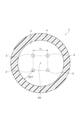
- FIG. 1 is a cross-sectional view perpendicular to the central axis of an MCF according to an embodiment.
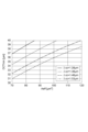
- FIG. 2 is a plot of the relationship between the effective area and the minimum adjacent core spacing at which XT is 10 ⁇ 4 /(100 km) 2 or less during counter propagation at a wavelength of 1625 nm, for a number of cutoff frequencies.
- FIG. 3 is a plot of the relationship between the lower limit of the outer cladding thickness at which the leakage loss is 0.001 dB/km or less at a wavelength of 1625 nm and the effective area for a number of cutoff frequencies.
- FIG. 1 is a cross-sectional view perpendicular to the central axis of an MCF according to an embodiment.
- FIG. 2 is a plot of the relationship between the effective area and the minimum adjacent core spacing at which XT is 10 ⁇ 4 /(100 km) 2 or less during counter propagation at a wavelength of 1625 nm, for a number of cutoff frequencies
- FIG. 4 is a plot of the relationship between the lower limit of the outer cladding thickness at which the leakage loss is 0.0005 dB/km or less at a wavelength of 1625 nm and the effective area for a number of ⁇ cc.
- FIG. 5 is a graph showing the relationship between the upper limit of the effective cross-sectional area and the cutoff wavelength, for a plurality of cladding diameters, where there is a central design value of the core pitch such that the XT at a wavelength of 1625 nm is ⁇ 40 dB/km or less and the leakage loss is 0.001 dB/km or less, even when the core pitch varies by ⁇ 1 ⁇ m from the central design value.
- FIG. 5 is a graph showing the relationship between the upper limit of the effective cross-sectional area and the cutoff wavelength, for a plurality of cladding diameters, where there is a central design value of the core pitch such that the XT at a wavelength of 1625 nm is ⁇ 40
- FIG. 6 is a graph showing the relationship between the upper limit of the effective cross-sectional area and the cutoff wavelength for a plurality of cladding diameters, where the core pitch has a central design value such that the XT at a wavelength of 1625 nm is ⁇ 40 dB/km or less and the leakage loss is 0.0005 dB/km or less, even when the core pitch varies by ⁇ 1 ⁇ m from the central design value.
- FIG. 7 is a cross-sectional view perpendicular to the central axis of the MCF according to the first modified example.
- FIG. 8 is a cross-sectional view perpendicular to the central axis of the MCF according to the second modified example.
- FIG. 9 is a diagram showing a refractive index profile around a core applicable to the MCF of the present disclosure.
- FIG. 10 is a diagram showing a refractive index profile around a core applicable to the MCF of the present disclosure.
- Non-Patent Document 2 describes that the MCF described in Patent Document 2 has an increased loss in the region of 1580 nm or more.
- the conventional technology has not been able to suppress the leakage loss at a wavelength of 1625 nm. Therefore, when transmitting over long distances using the L band (wavelengths from 1565 nm to 1625 nm), the transmission loss increases and the signal transmission quality deteriorates.
- the present disclosure provides an MCF that can suppress degradation of signal transmission quality in the wavelength range of 1530 nm or more and 1625 nm or less.
- An MCF according to one embodiment of the present disclosure comprises four cores each extending along a central axis of the MCF, a common cladding surrounding the four cores and having a refractive index lower than that of each of the four cores, and a coating resin surrounding the common cladding, wherein the diameter of the common cladding is 124.5 ⁇ m or more and 125.5 ⁇ m or less, and in each of the four cores, if the effective cross-sectional area at a wavelength of 1550 nm is Aeff [ ⁇ m2 ] and the cable cutoff wavelength is ⁇ cc [ ⁇ m], Aeff satisfies equations (1) and (2), and ⁇ cc satisfies equations (1) and (3).
- the four cores are arranged such that, in a cross section perpendicular to the central axis, if the center-to-center distance between a first core, which is one of the four cores, and a second core located closest to the first core is Dc [ ⁇ m], and the shortest distance between the interface between the common cladding and the coating resin and the center of the first core is OCT [ ⁇ m], Dc satisfies equation (4) for both Aeff and ⁇ cc of the first core and the second core, and the OCT, Aeff, and ⁇ cc of the first core satisfy equation (5).
- XT during parallel propagation between the first core and the second core at a wavelength of 1625 nm is 10 ⁇ 4 /km or less.
- leakage loss at a wavelength of 1625 nm is 0.001 dB/km or less. Therefore, degradation of signal transmission quality at a wavelength of 1625 nm can be suppressed.
- degradation of signal transmission quality can be suppressed in long-distance transmission by counter propagation at least in the wavelength range of 1530 nm to 1625 nm.
- Aeff may satisfy equation (6) and ⁇ cc may satisfy equation (7).
- degradation of signal transmission quality can be suppressed in long-distance transmission by counter propagation at least in the wavelength range of 1460 nm to 1625 nm, i.e., in the wavelength range of 1460 nm to 1625 nm or in the wavelength range of 1530 nm to 1625 nm.
- ⁇ may satisfy equation (8).
- confinement to the core can be strengthened, so that XT and leakage loss can be further suppressed.
- the four cores may be arranged such that the OCT, Aeff, and ⁇ cc of the first core satisfy formula (9).
- the leakage loss at a wavelength of 1625 nm is 0.0005 dB/km or less.
- the centers of the four cores may be arranged at the four vertices of a square with a side length of Dc. In this case, since the four cores are arranged symmetrically, the optical properties of the four cores can be made uniform.
- the centers of the four cores may be located at the four vertices of an isosceles trapezoid whose three sides are Dc and whose one side is longer than Dc. In this case, the cores can be identified without providing a marker.
- the common cladding may be provided in contact with the outer peripheral surfaces of the four cores. In this case, by not using a complex refractive index structure, manufacturability can be improved.
- the relative refractive index difference of each of the four cores based on the refractive index of the common cladding may be 0.50% or less. In this case, manufacturability can be improved by not using a deep depressed cladding or a refractive index trench. In addition, transmission loss can be reduced by not making the refractive index difference between the cores and the common cladding excessive.
- any one of the MCFs (1) to (6) above may further include four individual claddings surrounding each of the four cores inside the common cladding, and when the relative refractive index difference of each of the four individual claddings based on the refractive index of the common cladding is ⁇ ic [%], ⁇ ic may satisfy formula (10). In this case, manufacturability can be improved by not using deep depressed cladding or index trenches.
- any one of the MCFs (1) to (6) above may further include four individual claddings surrounding each of the four cores inside the common cladding, and the relative refractive index difference of the cores inside the individual claddings based on the refractive index of each individual cladding may be 0.50% or less.
- manufacturability can be improved by not using a deep depressed cladding or a refractive index trench.
- transmission loss can be reduced by not making the refractive index difference between the cores and the individual claddings excessive.
- FIG. 1 is a cross-sectional view perpendicular to the central axis of an MCF according to an embodiment.
- the MCF 1 according to an embodiment is a four-core fiber having four cores 2, a common cladding 3, and a coating resin 4.
- the cores 2 are made of glass containing silica as a main component.
- the four cores 2 In a cross-section perpendicular to the central axis AX, the four cores 2 have the same circular shape. Each of the four cores 2 extends along the central axis AX of the MCF 1.
- Dc the center distance between a first core, which is one of the four cores 2, and the second core located closest to the first core.
- Dc the center distance between a first core, which is one of the four cores 2, and the second core located closest to the first core.
- the centers of the four cores 2 are located at the four vertices of a square with a side length of Dc [ ⁇ m].
- the first core and the second core are adjacent cores, and Dc is the center distance between the adjacent cores.
- the four cores 2 are arranged symmetrically, so the optical characteristics can be made uniform between the four cores 2.
- each of the four cores 2 if the effective area at a wavelength of 1550 nm is Aeff [ ⁇ m 2 ] and the cable cutoff wavelength is ⁇ cc [ ⁇ m], Aeff satisfies formulas (1) and (2), and ⁇ cc satisfies formulas (1) and (3).
- the Aeffs of the four cores 2 may be the same as each other or different from each other.
- the ⁇ ccs of the four cores 2 may be the same as each other or different from each other.
- ⁇ cc in order for Aeff to be 70 ⁇ m2 or more, ⁇ cc needs to be 1270 nm or more.
- ⁇ cc In formula (1), in order for Aeff to be 70 ⁇ m2 or more, ⁇ cc needs to be 1270 nm or more.
- ⁇ cc In formula (1), in order for Aeff to be 70 ⁇ m2 or more, ⁇ cc needs to be 1270 nm or more.
- ⁇ cc in order for Aeff to be 1530 nm or less, Aeff needs to be 101.2 ⁇ m2 or less.
- Aeff may satisfy equation (6), and ⁇ cc may satisfy equation (7). In each of the four cores 2, ⁇ cc may further satisfy equation (8).
- equation (1) in order for ⁇ cc to be 1460 nm or less, Aeff needs to be 93.0 ⁇ m2 or less.
- the four cores 2 are arranged so that Dc satisfies formula (4) for Aeff and ⁇ cc of both the first core and the second core.
- XT during parallel propagation between adjacent cores at a wavelength of 1625 nm is 10 -4 /km or less. Therefore, XT during counter propagation between adjacent cores at a wavelength of 1625 nm (counter XT) can be made 10 -4 /(100km) 2 or less. This makes it possible to sufficiently suppress degradation of signal quality caused by XT during counter propagation.
- the transmission direction of optical signals is the same between adjacent cores. In counter propagation, the transmission direction of optical signals is different between adjacent cores.
- the transmission loss (span loss) of the optical fiber between adjacent amplifier repeaters (spans) is small. Therefore, based on Non-Patent Document 3, the predominant XT that is permissible from the viewpoint of suppressing degradation of signal quality is indirect XT, in which parallel-propagating optical signals are XTed via adjacent cores. Indirect XT is proportional to the square of the span length within each span. Therefore, 1/(100 km) 2 is used here as a unit. 10 ⁇ 4 /(100 km) 2 is equal to 10 ⁇ 8 /km 2. The accumulation of indirect XT across multiple spans is linear, that is, a simple sum of the indirect XT in each span.
- the counter XT in each span can be suppressed to approximately 10 ⁇ 4 /km or less in a counter propagation type multi-core optical fiber transmission system with an average span length of about 100 km or less.
- the deterioration of signal quality due to XT can be suppressed regardless of the optical fiber length (or the number of spans).
- the noise caused by XT can be suppressed more than the noise caused by optical amplifiers and the noise caused by nonlinear interference.
- XT during parallel propagation is set to a level at which deterioration of the optical signal transmission quality is suppressed or less. This makes it possible to realize a value that suppresses leakage loss in the OCT described below.
- FIG. 2 is a plot of the relationship between Aeff and the lower limit (Dmin) of Dc at which XT during counter propagation is 10 ⁇ 4 /(100 km) 2 or less at a wavelength of 1625 nm.
- the multiple ⁇ cc are 1.26 ⁇ m, 1.36 ⁇ m, 1.46 ⁇ m, and 1.53 ⁇ m.
- Equation (4) summarizes the relationship shown in Figure 2.
- Figure 2 was obtained by creating multiple combinations of Aeff, ⁇ cc, and Dmin. Specifically, multiple combinations of Aeff and ⁇ cc were created by varying the radius ra of core 2 and the relative refractive index difference ⁇ of the core, and Dmin was calculated for each combination.
- the common cladding 3 surrounds the four cores 2.
- the common cladding 3 is provided in contact with the outer peripheral surfaces of the four cores 2. There is no depressed cladding between the cores 2 and the common cladding 3. In this way, the MCF 1 does not use a complex refractive index structure, which improves manufacturability.
- the common cladding 3 is made of glass containing silica as a main component.
- the common cladding 3 has a refractive index lower than that of each of the four cores 2.
- the cores 2 may be doped with germanium (Ge).
- the common cladding 3 may be doped with fluorine (F).
- the relative refractive index difference ⁇ c of each core 2 is 0.50% or less based on the refractive index of the cladding in contact with the core 2.
- the cladding that serves as the reference for the refractive index is the common cladding 3.
- the relative refractive index difference ⁇ c of each core 2 based on the refractive index of the common cladding 3 is indicated by ⁇ 1.
- the relative refractive index difference ⁇ 1 of each of the four cores 2 based on the refractive index of the common cladding 3 is 0.50% or less. Since a deep depressed cladding or refractive index trench is not used, the manufacturability of the MCF 1 can be improved. By not making the refractive index difference excessive between the cores 2 and the common cladding 3, transmission loss can be suppressed.
- the diameter (cladding diameter) of the common cladding 3 is 124.5 ⁇ m or more and 125.5 ⁇ m or less.
- the common cladding 3 has the same diameter (2rb) as the cladding diameter of the widely used general-purpose single-mode optical fiber, so it is possible to achieve the same ease of handling and mechanical reliability.
- the coating resin 4 surrounds the common clad 3.
- the coating resin 4 is provided in contact with the outer peripheral surface of the common clad 3.
- the coating resin 4 is made of, for example, an ultraviolet-curable resin.
- the four cores 2 are arranged such that, in a cross section perpendicular to the central axis AX, the OCT, Aeff, and ⁇ cc of the first core satisfy equation (5), where the shortest distance between the interface between the common cladding 3 and the coating resin 4 and the center of the first core is OCT (outer cladding thickness) [ ⁇ m]. This makes it possible to reduce the leakage loss at a wavelength of 1625 nm to 0.001 dB/km or less.
- the four cores 2 may be arranged such that the OCT, Aeff, and ⁇ cc of the first core satisfy equation (9). This makes it possible to reduce the leakage loss at a wavelength of 1625 nm to 0.0005 dB/km or less.
- FIG. 3 is a plot of the relationship between the lower limit of OCT (OCTmin) at which the leakage loss is 0.001 dB/km or less at a wavelength of 1625 nm and Aeff for multiple ⁇ cc.
- the multiple ⁇ cc are 1.26 ⁇ m, 1.36 ⁇ m, 1.46 ⁇ m, and 1.53 ⁇ m.
- Equation (5) summarizes the relationship shown in Figure 3.
- Figure 3 was obtained by creating multiple combinations of Aeff, ⁇ cc, and OCTmin. Specifically, multiple combinations of Aeff and ⁇ cc were created by varying the radius ra of the core 2 and the relative refractive index difference ⁇ 1 of the core 2 based on the refractive index of the common cladding 3, and OCTmin was calculated for each combination.
- FIG. 4 is a plot of the relationship between the lower limit of OCT (OCTmin) at which the leakage loss is 0.0005 dB/km or less at a wavelength of 1625 nm and Aeff for multiple ⁇ cc.
- the multiple ⁇ cc are 1.26 ⁇ m, 1.36 ⁇ m, 1.46 ⁇ m, and 1.53 ⁇ m.
- Equation (9) summarizes the relationship shown in Figure 4.
- Figure 4 was obtained by creating multiple combinations of Aeff, ⁇ cc, and OCTmin. Specifically, multiple combinations of Aeff and ⁇ cc were created by varying the radius ra of the core 2 and the relative refractive index difference ⁇ of the core, and OCTmin was calculated for each combination.
- the leakage loss is largest when the diameter of the common cladding 3 is 124.5 ⁇ m. Even if the diameter of the common cladding 3 is 124.5 ⁇ m and the core pitch (Dc) varies by ⁇ 1 ⁇ m from the design center value, the relationship between Aeff and ⁇ cc at which the opposite XT satisfies 10 ⁇ 4 /(100 km) 2 at a wavelength of 1625 nm and there is a design center value of Dc at which the leakage loss is 0.001 dB/km or less is expressed by equation (1).
- FIG. 5 is a graph showing the relationship between the upper limit of Aeff and ⁇ cc, where the opposing XT at a wavelength of 1625 nm satisfies 10 ⁇ 4 /(100 km) 2 or less and the leakage loss is 0.001 dB/km or less, even if the core pitch varies by ⁇ 1 ⁇ m from the design center value, for a plurality of cladding diameters.
- the plurality of cladding diameters are set in the range of 124.5 ⁇ m or more and 125.5 ⁇ m or less.
- the plurality of cladding diameters are 124.5 ⁇ m, 124.75 ⁇ m, 125 ⁇ m, 125.25 ⁇ m, and 125.5 ⁇ m.
- FIG. 6 is a graph showing the relationship between the upper limit of Aeff and ⁇ cc, where the opposing XT satisfies 10 ⁇ 4 /(100km) 2 at a wavelength of 1625nm and the leakage loss is 0.0005dB/km or less, even if the core pitch varies by ⁇ 1 ⁇ m from the design center value for a plurality of cladding diameters in the range of 124.5 ⁇ m or more and 125.5 ⁇ m or less.
- the horizontal axis of FIG. 6 shows ⁇ cc [ ⁇ m], and the vertical axis shows the upper limit of Aeff.
- the innermost part of the approximately triangular region shown by the curve and the straight line corresponds to the range that satisfies formula (1), formula (6), and formula (7), respectively.
- XT during parallel propagation between adjacent cores at a wavelength of 1625 nm is 10 ⁇ 4 /km or less.
- leakage loss at a wavelength of 1625 nm is 0.001 dB/km or less. Therefore, degradation of signal transmission quality at a wavelength of 1625 nm can be suppressed.
- degradation of signal transmission quality can be suppressed in long-distance transmission by counter propagation at least in the wavelength range of 1530 nm to 1625 nm.
- Figure 7 is a cross-sectional view perpendicular to the central axis of the MCF according to the first modified example.
- the centers of the four cores 2 are located at the four vertices of an isosceles trapezoid with three sides of length Dc and one side longer than Dc.
- the cores 2 can be identified without providing a marker.
- Fig. 8 is a cross-sectional view perpendicular to the central axis of the MCF according to the second modification.
- the MCF 1B according to the second modification further includes four individual claddings 5.
- the four individual claddings 5 surround the four cores 2 inside the common cladding 3.
- ⁇ ic satisfies formula (10).
- the relative refractive index difference ⁇ c of each core 2 is 0.50% or less based on the refractive index of the cladding in contact with the core 2.
- the cladding that is the reference for the refractive index is the corresponding individual cladding 5, i.e., the individual cladding 5 that surrounds the core 2 from the inside. Since the MCF 1B does not use a deep depressed cladding or a refractive index trench, manufacturability can be improved. By preventing an excessive refractive index difference between the core 2 and the corresponding individual cladding 5, transmission loss can be suppressed.
- FIG. 9 is a diagram showing a refractive index profile around the core that can be applied to the MCF of the present disclosure.
- an appropriate structure can be selected for the refractive index profile of the core and the associated optical characteristics depending on the application.
- the refractive index profiles of patterns (A) to (J) shown in FIG. 9 are applicable.
- ⁇ is the relative refractive index difference based on the refractive index of the common cladding
- the structures may be the same between cores, or may be different.
- Pattern (A) shown in FIG. 9 is a step-type refractive index profile
- pattern (B) is a ring-type refractive index profile
- pattern (C) is a double-step-type refractive index profile
- pattern (D) is a graded-type refractive index profile
- pattern (E) is a tapered-type refractive index profile, which are applicable to the core structure in the MCF of the present disclosure.
- patterns (F) and (H) in which a depressed-type refractive index profile is provided around the core patterns (G), (I) and (J) in which a raised-type refractive index profile is provided around the core, and pattern (E) in which a matched-type refractive index profile is provided around the core are also applicable to the core structure.
- Pattern (A), pattern (B), pattern (C), and pattern (D) correspond to MCF1 according to the embodiment and MCF1A according to the first modified example.
- pattern (F) and pattern (H) satisfy formula (10), they correspond to MCF1B according to the second modified example.
- Non-Patent Document 4 can be easily applied when the boundary between the core and the cladding is clear.
- the ESI approximation can be performed by regarding r at which the refractive index profile before ESI approximation has a minimum d ⁇ /dr (the slope downward to the right is the steepest) as the core radius of the core before approximation.
- the relative refractive index difference ( ⁇ ic) of the individual cladding can be the average value of the relative refractive index difference of the core before approximation in the individual cladding part. In other words, the average value (rb-ra)/3+ra ⁇ r ⁇ 2(rb-ra)/3+ra at the center part from ra to rb on the horizontal axis (r axis) can be used.
- FIG. 10 is a diagram showing a refractive index profile around the core that can be applied to the MCF of the present disclosure.
- ⁇ is the relative refractive index difference based on the refractive index of the common cladding
- ⁇ is the relative refractive index difference based on the refractive index of the cladding in contact with the core.
- the relative refractive index difference of the core is shown as ⁇ c.
- the cladding that is the reference for the refractive index is the common cladding, so the refractive index profile is substantially the same as that of patterns (A) to (E) shown in FIG. 9.
- patterns (F) to (J) shown in FIG. 10 a cladding other than the common cladding is provided in contact with the core, so the refractive index profile is different from that of patterns (F) to (J) shown in FIG. 9.
- the refractive index profile around the core is not limited to the refractive index profiles of patterns (A) to (J) shown in Figures 9 and 10, respectively.
- the features and characteristics of the MCF disclosed herein can be measured by the following methods.
- the refractive indices of the core, common cladding, and individual cladding can be measured, for example, by the near-field refraction method or the lateral interference method.
- the diameter of the common cladding can be measured, for example, by the near-field refraction method or the lateral interference method, or from a microscopic image of the MCF cross section (transmission near-field method).
- the effective cross-sectional area Aeff can be measured, for example, by the method described in Appendix III of ITU-T G. 650.2 (08/2015).
- the cable cutoff wavelength ⁇ cc can be measured, for example, by the method described in Section 6.3 of ITU-T G.
- the center distance Dc between the first core and the second core located closest to the first core can be measured, for example, by the near-field refraction method or the lateral interference method, or from a microscopic image of the MCF cross section (transmission near-field method).
- the shortest distance OCT between the interface between the common cladding and the coating resin and the center of the first core can be measured, for example, by the refraction near-field method, the lateral interference method, or a microscope image of the MCF cross section (transmission near-field method).
- XT during parallel propagation can be measured by the method described in Non-Patent Document 5.
- XT during counter propagation can be predicted from XT during parallel propagation based on the formula described in Non-Patent Document 3.
- Leakage loss can be measured by the method described in Patent Document 3.
- the components that make up the multicore fiber can be measured by X-ray fluorescence analysis.
- the formulas still hold even if the symbols for the physical quantities and so forth mentioned above are considered not to include units, the symbols are considered to represent numerical values in the units listed next to the symbols, and formulas (1) to (10) are considered to be dimensionless.
- the numerical value of ⁇ cc used in the formulas is a numerical value in units of [ ⁇ m].
- the numerical value of ⁇ cc may be listed in units of [nm] for comparison with the wavelength of the optical signal.
Landscapes
- Physics & Mathematics (AREA)
- General Physics & Mathematics (AREA)
- Optics & Photonics (AREA)
- Optical Integrated Circuits (AREA)
- Optical Fibers, Optical Fiber Cores, And Optical Fiber Bundles (AREA)
Priority Applications (4)
| Application Number | Priority Date | Filing Date | Title |
|---|---|---|---|
| US18/725,402 US20250172745A1 (en) | 2022-11-30 | 2023-11-10 | Multi-core optical fiber |
| EP23897444.8A EP4628949A4 (en) | 2022-11-30 | 2023-11-10 | MULTI-CORE FIBER OPTIC |
| CN202380070905.3A CN119998701A (zh) | 2022-11-30 | 2023-11-10 | 多芯光纤 |
| JP2024561307A JPWO2024116792A1 (https=) | 2022-11-30 | 2023-11-10 |
Applications Claiming Priority (2)
| Application Number | Priority Date | Filing Date | Title |
|---|---|---|---|
| JP2022-192004 | 2022-11-30 | ||
| JP2022192004 | 2022-11-30 |
Publications (1)
| Publication Number | Publication Date |
|---|---|
| WO2024116792A1 true WO2024116792A1 (ja) | 2024-06-06 |
Family
ID=91323439
Family Applications (1)
| Application Number | Title | Priority Date | Filing Date |
|---|---|---|---|
| PCT/JP2023/040553 Ceased WO2024116792A1 (ja) | 2022-11-30 | 2023-11-10 | マルチコア光ファイバ |
Country Status (5)
| Country | Link |
|---|---|
| US (1) | US20250172745A1 (https=) |
| EP (1) | EP4628949A4 (https=) |
| JP (1) | JPWO2024116792A1 (https=) |
| CN (1) | CN119998701A (https=) |
| WO (1) | WO2024116792A1 (https=) |
Cited By (1)
| Publication number | Priority date | Publication date | Assignee | Title |
|---|---|---|---|---|
| EP4685530A1 (en) * | 2024-07-22 | 2026-01-28 | Lightera Japan Co., Ltd. | Multi-core fiber |
Citations (9)
| Publication number | Priority date | Publication date | Assignee | Title |
|---|---|---|---|---|
| JP2013088458A (ja) | 2011-10-13 | 2013-05-13 | Nippon Telegr & Teleph Corp <Ntt> | 多芯単一モード光ファイバおよび光ケーブル |
| JP2017509171A (ja) | 2013-11-22 | 2017-03-30 | クアルコム,インコーポレイテッド | 車両の外部にあるときにモバイルコンピューティングデバイスによって指定されるパラメータに基づいて車両構成を実施するためのシステムおよび方法 |
| JP2020086054A (ja) | 2018-11-21 | 2020-06-04 | 日本電信電話株式会社 | マルチコア光ファイバ、マルチコア光ファイバ設計方法、および光伝送方法 |
| JP2020115191A (ja) * | 2019-01-18 | 2020-07-30 | 日本電信電話株式会社 | マルチコア光ファイバ及び設計方法 |
| US20220043201A1 (en) * | 2020-08-10 | 2022-02-10 | Corning Incorporated | Ultra-low-loss coupled-core multicore optical fibers |
| WO2022034662A1 (ja) * | 2020-08-12 | 2022-02-17 | 日本電信電話株式会社 | マルチコア光ファイバ及び設計方法 |
| JP2022066053A (ja) * | 2020-10-16 | 2022-04-28 | 住友電気工業株式会社 | マルチコア光ファイバおよびマルチコア光ファイバケーブル |
| US20220283362A1 (en) * | 2021-03-05 | 2022-09-08 | Corning Incorporated | Multicore optical fiber |
| JP2022192004A (ja) | 2021-06-16 | 2022-12-28 | キヤノン株式会社 | 印刷制御装置、印刷制御装置の制御方法、及びプログラム |
-
2023
- 2023-11-10 US US18/725,402 patent/US20250172745A1/en active Pending
- 2023-11-10 WO PCT/JP2023/040553 patent/WO2024116792A1/ja not_active Ceased
- 2023-11-10 CN CN202380070905.3A patent/CN119998701A/zh active Pending
- 2023-11-10 JP JP2024561307A patent/JPWO2024116792A1/ja active Pending
- 2023-11-10 EP EP23897444.8A patent/EP4628949A4/en active Pending
Patent Citations (9)
| Publication number | Priority date | Publication date | Assignee | Title |
|---|---|---|---|---|
| JP2013088458A (ja) | 2011-10-13 | 2013-05-13 | Nippon Telegr & Teleph Corp <Ntt> | 多芯単一モード光ファイバおよび光ケーブル |
| JP2017509171A (ja) | 2013-11-22 | 2017-03-30 | クアルコム,インコーポレイテッド | 車両の外部にあるときにモバイルコンピューティングデバイスによって指定されるパラメータに基づいて車両構成を実施するためのシステムおよび方法 |
| JP2020086054A (ja) | 2018-11-21 | 2020-06-04 | 日本電信電話株式会社 | マルチコア光ファイバ、マルチコア光ファイバ設計方法、および光伝送方法 |
| JP2020115191A (ja) * | 2019-01-18 | 2020-07-30 | 日本電信電話株式会社 | マルチコア光ファイバ及び設計方法 |
| US20220043201A1 (en) * | 2020-08-10 | 2022-02-10 | Corning Incorporated | Ultra-low-loss coupled-core multicore optical fibers |
| WO2022034662A1 (ja) * | 2020-08-12 | 2022-02-17 | 日本電信電話株式会社 | マルチコア光ファイバ及び設計方法 |
| JP2022066053A (ja) * | 2020-10-16 | 2022-04-28 | 住友電気工業株式会社 | マルチコア光ファイバおよびマルチコア光ファイバケーブル |
| US20220283362A1 (en) * | 2021-03-05 | 2022-09-08 | Corning Incorporated | Multicore optical fiber |
| JP2022192004A (ja) | 2021-06-16 | 2022-12-28 | キヤノン株式会社 | 印刷制御装置、印刷制御装置の制御方法、及びプログラム |
Non-Patent Citations (7)
| Title |
|---|
| R. J. BLACKC. PASK, J. OPT. SOC. AM. A, JOSAA, vol. 1, no. 11, 1984, pages 1129 - 1131 |
| SAGAE YUTO, MATSUI TAKASHI; SAKAMOTO TAIJI; NAKAJIMA KAZUHIDE: "Ultra-Low Crosstalk Multi-Core Fiber with Standard 125-μm Cladding Diameter for 10,000km-Class Long-Haul Transmission", IEICE TRANSACTION ON COMMUNICATION, COMMUNICATIONS SOCIETY, TOKYO., JP, vol. E103.B, no. 11, 1 November 2020 (2020-11-01), JP , pages 1199 - 1205, XP093175423, ISSN: 0916-8516, DOI: 10.1587/transcom.2019OBI0001 * |
| See also references of EP4628949A1 |
| T. HAYASHI ET AL.: "Uncoupled Multi-core Fiber Design for Practical Bidirectional Optical Communications", OFC |
| T. MATSUI ET AL.: "STEP-INDEX PROFILE MULTI-CORE FIBRE WITH STANDARD 125 tM CLADDING TO FULL-BAND APPLICATION", ECOC, 2019 |
| Y. KOBAYASHIT. HAYASHI: "Behavior and measurement method of inter-core crosstalk in multicore fibers with core-dependent loss", OPT. EXPRESS, vol. 31, no. 1, 2023, pages 502 - 508 |
| Y. SAGAE ET AL.: "Ultra-Low-XT Multi-Core Fiber with Standard 125- tm Cladding for Long-Haul Transmission", OECC, 2019 |
Cited By (1)
| Publication number | Priority date | Publication date | Assignee | Title |
|---|---|---|---|---|
| EP4685530A1 (en) * | 2024-07-22 | 2026-01-28 | Lightera Japan Co., Ltd. | Multi-core fiber |
Also Published As
| Publication number | Publication date |
|---|---|
| CN119998701A (zh) | 2025-05-13 |
| EP4628949A4 (en) | 2026-03-11 |
| JPWO2024116792A1 (https=) | 2024-06-06 |
| EP4628949A1 (en) | 2025-10-08 |
| US20250172745A1 (en) | 2025-05-29 |
Similar Documents
| Publication | Publication Date | Title |
|---|---|---|
| US11828978B2 (en) | Multi-core optical fiber and multi-core optical fiber cable | |
| US20240288627A1 (en) | Multi-core optical fiber and multi-core optical fiber cable | |
| JP6361101B2 (ja) | 光ファイバ | |
| US11675121B2 (en) | Multi-core optical fiber and multi-core optical fiber cable | |
| KR20090049612A (ko) | 로우 밴드 손실 단일 모드 광섬유 | |
| JP2013167861A (ja) | マルチコアファイバ | |
| CN101915956A (zh) | 单模光纤 | |
| US8315494B2 (en) | Optical fiber | |
| US10884183B2 (en) | Weakly-coupled few mode optical fibers for mode division multiplexing and corresponding optical transmission system | |
| US12360309B2 (en) | Multi-core optical fiber and multi-core optical fiber cable | |
| US20230393332A1 (en) | Optical fiber cable | |
| US12197000B2 (en) | Reduced clad dual-core optical fibers for optical fiber cables and optical fiber interconnects | |
| WO2024116792A1 (ja) | マルチコア光ファイバ | |
| JPWO2024116792A5 (https=) | ||
| JP7505664B1 (ja) | マルチコア光ファイバ | |
| CN101523258A (zh) | 具有深抑制环的低弯曲损耗光纤 | |
| EP4664166A1 (en) | Multicore optical fiber and multicore optical fiber cable | |
| WO2024161793A1 (ja) | マルチコア光ファイバ | |
| US20250172746A1 (en) | Uncoupled multicore optical fiber |
Legal Events
| Date | Code | Title | Description |
|---|---|---|---|
| WWE | Wipo information: entry into national phase |
Ref document number: 18725402 Country of ref document: US |
|
| 121 | Ep: the epo has been informed by wipo that ep was designated in this application |
Ref document number: 23897444 Country of ref document: EP Kind code of ref document: A1 |
|
| WWE | Wipo information: entry into national phase |
Ref document number: 2024561307 Country of ref document: JP |
|
| WWE | Wipo information: entry into national phase |
Ref document number: 202380070905.3 Country of ref document: CN |
|
| WWP | Wipo information: published in national office |
Ref document number: 202380070905.3 Country of ref document: CN |
|
| WWP | Wipo information: published in national office |
Ref document number: 18725402 Country of ref document: US |
|
| WWE | Wipo information: entry into national phase |
Ref document number: 2023897444 Country of ref document: EP |
|
| NENP | Non-entry into the national phase |
Ref country code: DE |
|
| ENP | Entry into the national phase |
Ref document number: 2023897444 Country of ref document: EP Effective date: 20250630 |
|
| WWP | Wipo information: published in national office |
Ref document number: 2023897444 Country of ref document: EP |