WO2024116681A1 - 凍結装置、顕微鏡、凍結方法、及び観察方法 - Google Patents
凍結装置、顕微鏡、凍結方法、及び観察方法 Download PDFInfo
- Publication number
- WO2024116681A1 WO2024116681A1 PCT/JP2023/038854 JP2023038854W WO2024116681A1 WO 2024116681 A1 WO2024116681 A1 WO 2024116681A1 JP 2023038854 W JP2023038854 W JP 2023038854W WO 2024116681 A1 WO2024116681 A1 WO 2024116681A1
- Authority
- WO
- WIPO (PCT)
- Prior art keywords
- sample
- cryogen
- freezing
- liquid
- holder
- Prior art date
- Legal status (The legal status is an assumption and is not a legal conclusion. Google has not performed a legal analysis and makes no representation as to the accuracy of the status listed.)
- Ceased
Links
Images











Classifications
-
- G—PHYSICS
- G02—OPTICS
- G02B—OPTICAL ELEMENTS, SYSTEMS OR APPARATUS
- G02B21/00—Microscopes
- G02B21/24—Base structure
- G02B21/28—Base structure with cooling device
-
- C—CHEMISTRY; METALLURGY
- C12—BIOCHEMISTRY; BEER; SPIRITS; WINE; VINEGAR; MICROBIOLOGY; ENZYMOLOGY; MUTATION OR GENETIC ENGINEERING
- C12M—APPARATUS FOR ENZYMOLOGY OR MICROBIOLOGY; APPARATUS FOR CULTURING MICROORGANISMS FOR PRODUCING BIOMASS, FOR GROWING CELLS OR FOR OBTAINING FERMENTATION OR METABOLIC PRODUCTS, i.e. BIOREACTORS OR FERMENTERS
- C12M45/00—Means for pre-treatment of biological substances
- C12M45/20—Heating; Cooling
-
- C—CHEMISTRY; METALLURGY
- C12—BIOCHEMISTRY; BEER; SPIRITS; WINE; VINEGAR; MICROBIOLOGY; ENZYMOLOGY; MUTATION OR GENETIC ENGINEERING
- C12M—APPARATUS FOR ENZYMOLOGY OR MICROBIOLOGY; APPARATUS FOR CULTURING MICROORGANISMS FOR PRODUCING BIOMASS, FOR GROWING CELLS OR FOR OBTAINING FERMENTATION OR METABOLIC PRODUCTS, i.e. BIOREACTORS OR FERMENTERS
- C12M45/00—Means for pre-treatment of biological substances
- C12M45/22—Means for packing or storing viable microorganisms
-
- G—PHYSICS
- G01—MEASURING; TESTING
- G01N—INVESTIGATING OR ANALYSING MATERIALS BY DETERMINING THEIR CHEMICAL OR PHYSICAL PROPERTIES
- G01N1/00—Sampling; Preparing specimens for investigation
- G01N1/28—Preparing specimens for investigation including physical details of (bio-)chemical methods covered elsewhere, e.g. G01N33/50, C12Q
- G01N1/30—Staining; Impregnating ; Fixation; Dehydration; Multistep processes for preparing samples of tissue, cell or nucleic acid material and the like for analysis
- G01N1/31—Apparatus therefor
-
- G—PHYSICS
- G01—MEASURING; TESTING
- G01N—INVESTIGATING OR ANALYSING MATERIALS BY DETERMINING THEIR CHEMICAL OR PHYSICAL PROPERTIES
- G01N1/00—Sampling; Preparing specimens for investigation
- G01N1/28—Preparing specimens for investigation including physical details of (bio-)chemical methods covered elsewhere, e.g. G01N33/50, C12Q
- G01N1/42—Low-temperature sample treatment, e.g. cryofixation
-
- G—PHYSICS
- G02—OPTICS
- G02B—OPTICAL ELEMENTS, SYSTEMS OR APPARATUS
- G02B21/00—Microscopes
- G02B21/0004—Microscopes specially adapted for specific applications
- G02B21/002—Scanning microscopes
- G02B21/0024—Confocal scanning microscopes (CSOMs) or confocal "macroscopes"; Accessories which are not restricted to use with CSOMs, e.g. sample holders
- G02B21/0052—Optical details of the image generation
- G02B21/0076—Optical details of the image generation arrangements using fluorescence or luminescence
-
- G—PHYSICS
- G02—OPTICS
- G02B—OPTICAL ELEMENTS, SYSTEMS OR APPARATUS
- G02B21/00—Microscopes
- G02B21/0004—Microscopes specially adapted for specific applications
- G02B21/0088—Inverse microscopes
-
- G—PHYSICS
- G02—OPTICS
- G02B—OPTICAL ELEMENTS, SYSTEMS OR APPARATUS
- G02B21/00—Microscopes
- G02B21/24—Base structure
- G02B21/30—Base structure with heating device
-
- G—PHYSICS
- G02—OPTICS
- G02B—OPTICAL ELEMENTS, SYSTEMS OR APPARATUS
- G02B21/00—Microscopes
- G02B21/34—Microscope slides, e.g. mounting specimens on microscope slides
-
- G—PHYSICS
- G01—MEASURING; TESTING
- G01N—INVESTIGATING OR ANALYSING MATERIALS BY DETERMINING THEIR CHEMICAL OR PHYSICAL PROPERTIES
- G01N21/00—Investigating or analysing materials by the use of optical means, i.e. using sub-millimetre waves, infrared, visible or ultraviolet light
- G01N21/62—Systems in which the material investigated is excited whereby it emits light or causes a change in wavelength of the incident light
- G01N21/63—Systems in which the material investigated is excited whereby it emits light or causes a change in wavelength of the incident light optically excited
- G01N21/64—Fluorescence; Phosphorescence
- G01N21/645—Specially adapted constructive features of fluorimeters
- G01N21/6456—Spatial resolved fluorescence measurements; Imaging
- G01N21/6458—Fluorescence microscopy
Definitions
- the present invention relates to a freezing device, a microscope, a freezing method, and an observation method, and more particularly to a technique for freezing a sample.
- the sample When observing biological samples with an optical microscope, the sample may be fixed in advance to prevent changes to the sample during observation or due to pre-treatment.
- chemical fixation with aldehydes that cross-link proteins or dehydration fixation with organic solvents are used. These fixation methods are sufficient to maintain morphological information at the level of optical microscope observation.
- some molecules may be oxidized by aldehydes or dissolved in organic solvents.
- the fixation reaction may take minutes, and for thick samples, even more time may be required to fix the deeper parts. Another problem is that not all molecules are fixed.
- cryofixation is a method that physically stops the movement of molecules and ions in a sample by freezing the water. If freezing is performed in a short period of time, the biological sample can be fixed in its original state. This allows the cells to be observed and preserved in their original state.
- Non-Patent Document 1 discloses a method using a heat sink and heater.
- a thin NiCr heater is placed on top of a heat sink cooled with liquid nitrogen.
- a sample placed on the heater is frozen at any time by controlling the heater's on/off state.
- the sample volume is reduced by placing the sample in a microchannel.
- nematodes have been successfully frozen in a few tens of milliseconds.
- the freezing speed is limited by the thickness of the heater.
- Non-Patent Document 2 discloses a method of freezing a sample using a diamond substrate.
- the diamond substrate is pressed against a sample and cooled with liquid nitrogen.
- the nitrogen gas generated on the diamond substrate is evacuated.
- This method has restrictions on sample manipulation (addition of chemicals, etc.) and maintenance of the sample's surrounding environment (ion concentration, etc.) during microscopic observation. In addition, it is unclear how quickly the sample can be frozen.
- the present disclosure has been made in consideration of the above points, and aims to provide a freezing device, microscope, freezing method, and observation method that can properly freeze samples.
- the freezing device of this embodiment includes a sample holder that holds a sample containing the liquid in a state in which the volume of the liquid in the cryogen contact area is different from the volume of the liquid outside the cryogen contact area, and a sample freezing means that freezes the sample in the cryogen contact area with a cryogen.
- the sample holder may hold the sample in a state in which the liquid level of the sample in the cryogen contact area is lower than the outside of the cryogen contact area.
- the freezing device may have an adjustment mechanism for adjusting the height of the liquid surface.
- the sample holder is provided with a through hole,
- the liquid level may be adjusted by sucking the liquid through the through-hole.
- the freezing device may be provided with a first supply port through which a chemical fixative for chemically fixing the sample is supplied to the space surrounded by the sample holder, and a second supply port through which a staining dye for staining the sample or a decolorizing agent for decolorizing the stained sample is supplied to the space.
- the sample holder may be provided with a sample holder that holds the sample, and the sample holder may have an opening that corresponds to the cryogen contact area.
- the height of the liquid surface may be adjusted by pressing a pressing member provided above the sample against the sample.
- the freezing device may further include a low-temperature maintenance mechanism that maintains the cryogen at a low temperature after the sample is frozen.
- the freezing device may further include a measuring mechanism for measuring the height of the liquid surface.
- the sample after freezing the sample, the sample may be stored in a frozen state.
- samples stored in a frozen state may be thawed and cultured.
- the microscope according to this embodiment may include the freezing device described above and an objective lens that receives light from the sample, the cryogen contact area corresponding to the field of view of the objective lens, and the sample freezing means freezing the sample in the field of view of the objective lens.
- the microscope further includes a cooling block disposed directly above the sample, the cooling block includes a cooling pipe for circulating a liquid for cooling the cooling block, and a through hole for passing a cryogen for freezing the sample.
- the cooling block may include at least one of a temperature sensor and a heater.
- the freezing method includes the steps of: a sample holder holds a sample containing liquid in a state in which the volume of the liquid in the sample in a cryogen contact area is different from the volume of the liquid outside the cryogen contact area; and freezing the sample in the cryogen contact area with a cryogen.
- the observation method includes the steps of freezing the sample in the field of view of the objective lens by the above-mentioned freezing method, and observing the frozen sample in the cryogen contact area using the objective lens.
- the sample may be observed while it is frozen.
- the present disclosure provides a freezing device, a microscope, a freezing method, and an observation method that can appropriately freeze a sample.
- FIG. 1 is an XZ sectional view showing a schematic diagram of an overall configuration of a microscope using a sample holder according to a first embodiment
- FIG. 2 is an enlarged XZ sectional view showing the configuration of the sample holder.
- FIG. 2 is a perspective view showing a configuration of a sample setting unit according to an embodiment.
- FIG. 2 is an exploded perspective view showing the configuration of a sample setting unit according to an embodiment.
- 4 is an XZ sectional view showing the configuration of a sample placement unit according to an embodiment;
- FIG. FIG. 13 is an XZ cross-sectional view showing a state in which a metal member for maintaining the cooling of the cryogen is inserted.
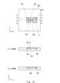
- 13A and 13B are diagrams showing tomographic images captured by changing the height of the liquid surface.
- FIG. 1 is an XZ sectional view showing a configuration in which a pressing member that is pressed against a sample is provided.
- FIG. FIG. 11 is a schematic diagram showing a configuration of a microscope according to a second embodiment.
- FIG. 11 is an XZ sectional view showing a schematic configuration of a microscope according to a third embodiment.
- FIG. 13 is a schematic diagram showing a configuration of a sample holder of a microscope according to a third embodiment.
- FIG. 13 is an XZ cross-sectional view illustrating a schematic configuration according to a modified example of the third embodiment.
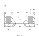
- 13A to 13C are diagrams for explaining a sample substrate and a freezing method according to a fourth embodiment.
- 11A to 11C are diagrams for explaining a method for thawing a sample substrate.
- FIG. 1 is a diagram for explaining a method for observing a frozen sample.
- FIG. 1 is a diagram for explaining a method for observing a thawed and refrozen sample.
- FIG. 1 is a diagram showing a configuration of a sample substrate having a reservoir.
- 4 is an XZ sectional view showing the configuration of a sample holder for holding a sample substrate.
- FIG. 11A and 11B are cross-sectional views for explaining a method for adjusting the amount of liquid on a sample substrate.
- 11A and 11B are cross-sectional views for explaining a method for adjusting the amount of liquid on a sample substrate.
- FIG. 2 is a cross-sectional view showing a schematic configuration of a sample holder.
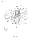
- FIG. 2 is an exploded perspective view showing the configuration of a sample holder having a cooling block.
- FIG. 2 is a cross-sectional view showing the configuration of a sample holder having a cooling block.
- a freezing device, a freezing method, a microscope, and an observation method according to the present embodiment will be described.
- the freezing device will be described as being mounted on a microscope, but the freezing device does not have to be mounted on a microscope.
- the freezing device and the freezing method can be used for purposes other than observation with a microscope.
- a sample can be frozen and preserved by the freezing method using the freezing device.
- samples stored in a frozen state may be thawed and cultured.
- a culture device or the like cultures the cells of the sample.
- the cultured samples can be used in regenerative medicine, reproductive medicine, cell medicines, drug discovery research, livestock farming, food production, etc.
- a sample in a frozen state can be observed.
- the sample can be fixed in a frozen state. This allows the exposure time of the photodetector to be extended, enabling observation with a high signal-to-noise ratio.
- a sample labeled with a fluorescent substance may be observed with a fluorescence microscope.
- an unlabeled sample may be observed with a microscope.
- the optical microscope (hereinafter simply referred to as the microscope) according to this embodiment freezes a sample using a cryogen.
- the microscope has a sample freezing means that supplies a cryogen.
- the sample freezing means supplies a cryogen to a sample in the field of view of the objective lens.
- the cryogen supplied from the sample freezing means freezes the sample.
- the sample in the field of view of the objective lens can be frozen. This makes it easy to observe the sample being frozen or the frozen sample.
- Figure 1 is a diagram showing the overall configuration of the microscope.
- an XYZ three-dimensional Cartesian coordinate system is shown as appropriate.
- the Z direction is parallel to the optical axis.
- the XY plane is a plane perpendicular to the Z direction, and is the focal plane on which the sample is placed.
- the microscope 10 includes a microscope body 12, a sample mounting section 100, an objective lens 210, a syringe 300, and a cryogen supply device 500. Since the microscope 10 is an inverted microscope, the objective lens 210 is disposed below the sample S. The objective lens 210 may be provided with a mechanism for returning the focal plane of the objective lens to the observation position when the position of the objective lens is displaced in the Z direction from the observation position of the sample. For example, this mechanism uses a piezo stage for the objective lens. Of course, the microscope 10 may be an upright microscope. In the case of an upright microscope, the objective lens 210 is disposed above the sample S. The sample S contains liquid.
- the sample installation section 100 includes a first plate 110, a second plate 120, and a sample holder 400.
- the sample holder 400 holds a sample S. The configuration of the sample holder 400 will be described later.
- the sample holder 400 is placed on the second plate 120.
- the first plate 110 is placed on the second plate 120.
- the first plate 110 is detachable from the second plate 120.
- the second plate 120 may have a mechanism for fixing the first plate 110.
- the second plate 120 is fixed to a microscope stage or the like via a plate for fixing to the microscope stage or the like.
- the second plate 120 is arranged so as to cover the peripheral portion of the sample holder 400.
- the sample holder 400 is held between the second plate 120 and the first plate 110.
- the second plate 120 and the first plate 110 are formed to be hollow.
- the hollow portion between the first plate 110 and the second plate 120 provides a space for placing the objective lens 210 and the sample holder 400.
- the first plate 110 has a cylindrical portion 112 extending upward.
- the hollow space of the cylindrical portion 112 serves as a cryogen storage tank 111 for storing a cryogen.
- Liquid cryogen 501 is charged into the cryogen storage tank 111 from a cryogen charging device 500.
- the cryogen 501 is an organic solvent, and can be, for example, a liquid propane-isopentane mixed solution.
- the cryogen 501 can be liquid ethane, liquid propane, etc.
- the cryogen 501 can be a solid.
- the cryogen supply device 500 drops the cryogen 501 from above into the cryogen storage tank 111.
- the cryogen 501 supplied to the cryogen storage tank 111 comes into contact with the sample S in the field of view 140 of the objective lens 210. This causes the sample S in the field of view 140 to be cooled and frozen.
- the cryogen 501 is in contact with the sample S, and by storing the cryogen 501 in the cryogen storage tank 111, the sample S can be efficiently cooled to the temperature of the cryogen 501.
- An outlet (not shown) for the cryogen 501 may be provided in the first plate 110 to remove the cryogen 501 stored in the cryogen storage tank 111. This allows the cryogen supply device 500 to continue supplying the cryogen 501.
- the cryogen storage tank 111 and the cryogen supply device 500 etc. constitute a sample freezing mechanism that freezes the sample S with the cryogen 501.
- a high-speed electromagnetic valve etc. is provided in the flow path of the liquid cryogen 501. By controlling the opening and closing of the valve, it is possible to freeze the sample S at the desired timing.
- the opening and closing of the electromagnetic valve may also be controlled by a signal from the sample S. Alternatively, the user may manually supply the cryogen 501.
- the objective lens 210 is disposed directly below the sample S.
- the hollow portion provided in the second plate 120 becomes the objective lens space G1 in which the objective lens 210 is disposed.
- the microscope body 12 is disposed below the objective lens 210.
- the microscope body 12 is provided with an optical system for propagating the illumination light and the observation light.
- the microscope body 12 includes a light source 201, a lens 202, a beam splitter 203, an imaging lens 204, and a photodetector 205.
- Light source 201 generates light for illuminating sample S.
- the illumination light from light source 201 is refracted by lens 202 and enters beam splitter 203.
- Beam splitter 203 is a half mirror or the like, which transmits approximately half of the incident light and reflects approximately the other half. Beam splitter 203 reflects a portion of the illumination light towards objective lens 210. Objective lens 210 focuses the illumination light on sample S. In this way, sample S can be illuminated.
- the objective lens 210 receives light from the sample S.
- the light from the sample S is refracted by the objective lens 210 and enters the beam splitter 203.
- the light that passes through the beam splitter 203 enters the photodetector 205 via the imaging lens 204.
- the imaging lens 204 forms an image of the sample S on the photodetector 205.
- the photodetector 205 is a CCD camera or a CMOS sensor, and has multiple pixels arranged in a two-dimensional array. Therefore, the photodetector 205 can capture an enlarged image of the sample S.
- the optical system of the microscope body 12 is not limited to the optical system shown in the figure.
- optical filters such as wavelength filters may be arranged in the optical system.
- the syringe 300 is an adjustment mechanism for adjusting the height of the liquid surface of the sample S.
- the syringe 300 is provided with a micrometer 301 and a screw mechanism.
- the syringe 300 is connected to the through hole 114 of the first plate 110 via a piping tube 310.
- the through hole 114 is connected to the sample space G2 in the sample holder 400.
- the syringe 300 can adjust the pressure of the sample space G2 around the sample S. In other words, by operating the syringe 300 with the micrometer 301, it is possible to suck in gas in the sample space G2 or supply gas to the sample space G2. This makes it possible to adjust the air pressure in the sample space G2 in which the sample S is located.
- the method for adjusting the height of the liquid surface can be a method other than gas suction or gas supply.
- a sample holder which will be described later, may be used, or an absorbent material that absorbs liquid may be used. By bringing the absorbent material into contact with the liquid, the liquid level will be lowered.
- the syringe 300 with the micrometer 301 may be a mechanism that is electrically controlled by an external signal. In this case, it is also possible to control the liquid level adjustment by the syringe 300 with the micrometer 301 and the timing of the cryogen injection by the cryogen injection device 500.
- the sample installation unit 100 may also be equipped with a measurement mechanism for measuring the height of the liquid surface in the field of view 140.
- the measurement mechanism for measuring the liquid surface height detects reflected light from the liquid surface using the objective lens 210 and the photodetector 205.
- the measurement mechanism may measure the liquid surface height from the top of the field of view using a laser surveyor or the like.
- the measurement mechanism may be a mechanism in which a pair of electrodes is placed on either side of the field of view, and the liquid volume is estimated from the value of the current flowing through the liquid.
- the measurement mechanism can be used for height adjustment and timing control of the start of freezing.
- the second plate 120 has a through hole 124 formed therein, which is connected to the objective lens space G1 in which the objective lens 210 is disposed.
- the through hole 124 is formed along the X direction.
- the through hole 124 penetrates from the outer peripheral surface to the inner peripheral surface of the second plate 120.
- an inert gas 450 is supplied to the through hole 124.
- the inert gas 450 is, for example, dry nitrogen gas.
- the inert gas 450 is supplied to the objective lens space G1 via the through hole 124.
- rubber 130 is provided around the objective lens 210.
- the rubber 130 is a sheet formed of, for example, silicone resin.
- the rubber 130 has a hole for inserting the objective lens 210.
- the objective lens 210 is fitted into the rubber 130.
- the objective lens space G1 surrounded by the rubber 130, the sample holder 400, the objective lens 210, and the second plate 120 becomes a nitrogen atmosphere. This makes it possible to prevent condensation on the objective lens 210.
- the second plate 120 may be provided with an exhaust port for nitrogen gas.
- FIG. 2 is an enlarged XZ cross-sectional view of the sample holder 400 and its surroundings.
- the sample holder 400 includes a substrate 401, a wall 403, a spacer 405, a base 411, a sample holder 412, and an O-ring O1.
- the substrate 401 is a plate made of a transparent material. More specifically, the substrate 401 is, for example, a cover glass made of soda glass or quartz.
- the sample S is placed on the substrate 401.
- the sample S contains a liquid S1 and a biological sample S2.
- the liquid S1 is a buffer solution or a culture medium.
- the biological sample S2 is a cultured cell, for example, and is placed in the liquid S1. Since the biological sample S2 is immersed in the liquid S1, it is possible to prevent the biological sample S2 from drying.
- the illumination light from the objective lens 210 passes through the substrate 401 and illuminates the sample S. Also, the observation light from the sample S passes through the substrate 401 and enters the objective lens 210.
- a wall 403 is disposed on the substrate 401.
- the wall 403 is formed in the shape of a closed ring in the XY plane.
- the wall 403 forms a liquid reservoir for holding the sample S having the liquid S1. Since the sample S is surrounded by the wall 403, the liquid S1 is held back by the wall 403. Thus, the sample S is held with the liquid level of the liquid S1 at a predetermined height.
- the wall 403 is formed of a material such as silicone rubber that does not absorb water.
- the wall 403 may be adhesively fixed to the substrate 401.
- the substrate 401 is placed on a base 411 having an opening. Therefore, the peripheral portion of the substrate 401 is placed on the base 411.
- a sample holder 412 is placed on the peripheral portion of the base 411.
- the base 411 serves as the lower holder, and the sample holder 412 serves as the upper holder.
- the sample holder 412 is placed on the base 411 via a spacer 405.
- An O-ring O1 for sealing the sample space G2 is placed between the sample holder 412 and the base 411.
- the member for sealing the sample space G2 is not limited to an O-ring, and rubber, metal, liquid, etc. can be used.
- the sample holder 412 extends from the outside of the wall 403 to above the sample S.
- the sample holder 412 has an opening 412a.
- the distance between the tip of the sample holder 412 and the substrate 401 at the opening 412a can be adjusted by the spacer 405.
- the distance between the tip of the sample holder 412 and the substrate 401 is about 20 to 100 ⁇ m.
- the opening 412a is disposed on the optical axis of the objective lens 210, that is, in the field of view 140.
- the opening 412a is, for example, a circle with a diameter of about several mm so as to correspond to the field of view 140.
- the opening 412a may also be square or rectangular.
- the size of the opening 412a is not particularly limited. By making the opening 412a larger, it becomes possible to freeze a large number of cells at the same time. This makes it possible to appropriately freeze and store the sample.
- the sample holder 412 is in contact with the liquid S1 outside the field of view 140 of the objective lens 210.
- a difference occurs in the level of the liquid S1 outside and inside the opening 412a.
- the level of the liquid inside the opening 412a is lower than the level of the liquid outside.
- the level of the liquid in the field of view 140 of the objective lens 210 can be made lower than the level of the liquid outside the field of view 140.
- the state of the inside and outside of the opening 412a is not limited to a state that creates a difference in the level of the liquid inside and outside. For example, if the liquid storage volume outside the opening 412a is larger than the inside, the level of the liquid outside the opening 412a does not have to be higher than the inside.
- the sample holder 400 can be used for purposes other than microscopy.
- the sample holder 400 and the cryogen input device 500 can be applied to a freezing device for freezing a sample.
- the sample holder 400 may hold a sample in a state in which the volume of liquid in the cryogen contact area that freezes the sample is different from the volume of liquid in the area outside the cryogen contact area.
- the cryogen input device 500 freezes the sample S in the cryogen contact area with the cryogen 501. For example, this allows the sample to be properly preserved.
- the field of view of the objective lens 210 corresponds to the cryogen contact area.
- the cryogen contact area can be said to be the area of the sample with which the cryogen comes into direct contact.
- the cryogen contact area may be adjusted or changed by adjusting or changing the contact range of the cryogen.
- the sample S freezes in the cryogen contact area. Furthermore, the sample S may also freeze outside the cryogen contact area.
- the cryogen passes through the opening 412a and comes into contact with the sample. Therefore, the cryogen contact area can be said to be the area corresponding to the opening 412a through which the cryogen is supplied.
- the user can observe the frozen sample S.
- the cryogen supply device 500 may supply cryogen 501 while the sample S is being observed. This allows the user to observe the sample S while the sample S is being frozen by the cryogen 501. Therefore, the user can observe how the sample S gradually freezes.
- the user may adjust the timing of freezing during observation. That is, when the appropriate timing arrives while observing the sample S, the user operates the cryogen supply device 500 to supply the cryogen 501.
- the user can control the timing of supplying the cryogen by opening and closing a valve or the like provided on the cryogen supply device 500. This allows the user to freeze the sample at the timing desired.
- the valve may be opened and closed by the user observing the sample operating a switch or the like.
- a control unit that controls the opening and closing of the valve may be provided in the microscope.
- the control unit uses various signals to control the opening and closing of the valve. This makes it possible to automatically adjust the timing of freezing.
- Various signals can be used as the signal that triggers the opening and closing of the valve.
- the opening and closing of the valve may be controlled based on a signal from the sample S.
- the control unit outputs a control signal based on an optical signal or an electrical signal from the sample.
- the optical signal from the sample S may be the intensity of scattered light or the intensity of fluorescence.
- the sample S may be imaged and the valve may be opened and closed depending on its morphology, such as its shape and size. For example, if the sample S is a pulsating organ, the control unit outputs a control signal in response to changes in the shape of the sample S. This makes it possible to freeze the sample S in sync with the pulsation timing.
- the control unit opens and closes the valve in response to the signal for providing the stimulus.
- the stimulus for the sample S is not limited to an optical stimulus, an electrical stimulus, an electromagnetic stimulus, or a magnetic stimulus.
- the stimulus for the sample S can be provided by a drug, temperature, a mechanical stimulus, an electromagnetic wave, an electron beam, radiation, optogenetics, photodissociation of a caged compound, or the like.
- the sample holder 412, base 411, spacer 405, etc. are made of materials that expand and contract little due to temperature changes.
- the sample holder 412, base 411, spacer 405, etc. are made of materials with a low thermal expansion coefficient.
- the sample holder 412, base 411, and spacer 405 can be made of stainless steel, Invar alloy, super Invar alloy, etc.
- the first plate 110 has a through hole 114. As shown in FIG. 1, the sample space G2 and the syringe 300 are connected via the through hole 114 of the first plate 110. This makes it possible to adjust the height of the liquid surface in the field of view 140.
- the syringe 300 supplies gas to the sample space G2, the pressure in the sample space G2 increases. As a result, the liquid level in the field of view 140 increases. Also, when the syringe 300 sucks air from within the sample space G2, the pressure in the sample space G2 decreases. As a result, the liquid level in the field of view 140 decreases. Because the air pressure in the sample space G2 is lower than the air pressure in the cryogen reservoir 111, the liquid level in the field of view 140 decreases. In this way, the user can adjust the height of the liquid level of the liquid S1 in the field of view 140. In other words, the user can adjust the amount of liquid in the field of view 140. The user freezes and observes the sample S with the liquid level in the field of view 140 at about 20 to 100 ⁇ m.
- the syringe 300 or the like can be used as a liquid volume adjustment mechanism.
- the sample can be frozen and fixed easily and with high reproducibility.
- the liquid level can be kept almost constant, allowing for highly reproducible observations.
- a suction mechanism other than the syringe 300 can be used to make the sample space G2 a negative pressure space.
- mechanisms other than a suction mechanism can be used as long as they use a pressure difference to adjust the liquid level.
- a sufficient amount of liquid S1 is secured in the liquid storage tank formed by the wall 403.
- the liquid storage tank formed by the wall 403 is larger than the opening 412a.
- the biological sample S2 is unlikely to dry out.
- the cryogen supply device 500 supplies liquid cryogen 501 at any timing while observing with the microscope. As soon as the cryogen 501 comes into contact with the sample S, the temperature of the sample S drops and the sample S is immediately frozen. Since the height of the liquid surface in the field of view 140 is set to about 20 to 100 ⁇ m, the sample S can be frozen in a short time of about several msec.
- cryogen tank 111 reaches the surface of the sample S. Therefore, chemicals and the like can be added to the sample S from the cryogen tank 111 side until just before the cryogen is added. Since liquids such as reagents can be supplied from the cryogen tank 111 at the appropriate time, the environment around the sample can be maintained at an optimal level for the sample S.
- the microscope 10 may also be equipped with a low-temperature maintenance mechanism that maintains the cryogen at a low temperature after the sample is frozen.
- a metal member at liquid nitrogen temperature may be placed in the cryogen reservoir 111 to maintain the temperature of the sample S at a low temperature.
- a metal rod cooled to -180°C to -190°C with liquid nitrogen is brought into contact with the cryogen 501.
- the sample holder 400 may also be cooled from the surroundings to maintain a low temperature.
- the microscope 10 may also have a replacement device that replaces the cryogen 501 with liquid nitrogen after freezing the sample S.
- a discharge path for the cryogen 501 is provided in the cryogen storage tank 111. After freezing with the cryogen 501, liquid nitrogen is supplied to the cryogen storage tank 111 and the cryogen 501 is discharged from the discharge path. This allows the cryogen 501 to be replaced with liquid nitrogen. Even if background light is generated by the cryogen, the effect on optical measurement can be suppressed. If the cryogen 501, which is an organic solvent, affects optical measurement, more appropriate observation can be made by replacing the cryogen 501 in the cryogen storage tank 111 with liquid nitrogen.
- the sample setting unit 100 may also have a mechanism that allows the frozen sample S to be transferred to a cryopreservation device while still in a frozen state after freezing the sample S.
- the frozen sample S is transferred to a container filled with liquid nitrogen and then transferred to a device that can store the sample frozen at liquid nitrogen temperatures. This allows the sample to be frozen and preserved, and can be observed using techniques other than electron microscopy.
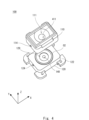
- Fig. 3 is a perspective view showing the sample mounting part 100
- Fig. 4 is an exploded perspective view of the sample mounting part 100
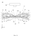
- Fig. 5 is a cross-sectional view showing the configuration of the sample mounting part 100.
- the first plate 110 is disposed on the second plate 120.
- An O-ring O2 is disposed between the first plate 110 and the second plate 120.
- a through-hole 124 is formed on the side of the second plate 120.
- nitrogen gas or the like is supplied to the through-hole 124 to prevent condensation on the objective lens 210.
- An adapter 122 is provided on the second plate 120.
- the adapter 122 has a bolt hole and is fixed to the microscope stage by a bolt or the like.
- a cryogen tank 111 is formed on the top surface of the first plate 110.
- the cryogen tank 111 is formed in a cone shape and reaches the field of view 140 of the objective lens 210.
- a through hole 114 is formed on the side of the first plate 110. As shown in FIG. 5, the through hole 114 reaches the sample space G2.
- a piping tube 310 (see FIG. 1) is connected to the through hole 114. Thus, the air pressure in the sample space G2 can be adjusted.
- the through holes 114 are provided on both sides of the first plate 110. That is, the first plate 110 has a through hole 114 that extends from the sample space G2 to the +X side and a through hole 114 that extends from the sample space G2 to the -X side.
- the space inside the O-ring O2 becomes the storage space G for the sample holder 400.
- the storage space 129 is a circular space when viewed in the XY plane.
- the sample holder 400 is placed on the storage space 129, the sample holder 400 is held between the first plate 110 and the second plate 120.
- the sample holder 400 is stored in the storage space 129, the sample S is placed in the field of view 140.
- O-rings O3 and O4 are provided on the outer circumferential surface of the sample holder 400.
- the O-rings O3 and O4 are disposed between the first plate 110 and the sample holder 400. Specifically, the O-rings O3 and O4 are in contact with the outer circumferential surface of the sample holder 412. This maintains the airtightness of the sample space G2. This allows the air pressure to be appropriately adjusted by the syringe 300.
- the sample holder 400 has a sample holder 412.
- the sample holder 412 is placed on the sample S.
- the sample S is placed on the substrate shown in FIG. 2, but is not shown in FIG. 5. In other words, in FIG. 5, the sample S is shown including the substrate 401.
- the tip of the sample holder 412 is in contact with the sample S.
- the sample S contains liquid, and the sample holder 412 is in contact with the surface of the liquid.
- the sample holder 412 has an opening in the area of the field of view 140. In other words, outside the field of view 140, the sample holder 412 is in contact with the sample S.
- the cryogen supply device 500 When the cryogen supply device 500 drops the cryogen 501 into the cryogen storage tank 111, the cryogen 501 reaches the sample S. When the cryogen 501 comes into contact with the surface of the sample S, the sample S in the field of view 140 is frozen. Furthermore, as shown in FIG. 6, the cryogen supply device 500 may have a metal member 503 for maintaining a low temperature. The cryogen supply device 500 inserts the cooled metal member 503 into the cryogen storage tank 111. When the metal member 503 comes into contact with the cryogen 501, the cryogen 501 is maintained at a low temperature.
- the metal member 503 is a metal rod or metal block cooled to the liquid nitrogen temperature. Liquid nitrogen may be circulating inside the metal member 503.
- the temperature of the cryogen 501 can be maintained at a low temperature.
- the metal member 503 becomes a mechanism for maintaining a low temperature after the cryogen is supplied.
- the mechanism for maintaining the sample at a low temperature is not limited to the configuration shown in FIG. 6.
- the sample holder 400 may be cooled with liquid nitrogen or the like.
- the sample mounting section 100 on which the sample S is mounted is mounted on the stage of an inverted fluorescence microscope.
- the sample S contains cultured cells and a buffer solution.
- the liquid level of the buffer solution is reduced to approximately 20-100 ⁇ m by adjusting the pressure in the space around the sample S.
- a liquid propane/isopentane mixed cryogen is added at any time to freeze and fix the sample.
- a metal member 503 at liquid nitrogen temperature is inserted into the cryogen reservoir, and fluorescence observation is continued while maintaining a low temperature. Since the sample S is fixed, the exposure time can be extended and fluorescence observation can be performed with a high signal-to-noise ratio. Super-resolution fluorescence microscope observation can also be performed over a long period of time.
- FIG. 7 shows the tomographic images obtained by changing the height of the liquid surface.
- the tomographic images are measured by moving the objective lens 210 up and down.
- the fluorescent dye solution L1 is placed on the substrate 401, which is a cover glass.
- the tomographic images are measured using a laser scanning fluorescence microscope.
- FIG. 7 shows three tomographic images taken with the height of the liquid surface changed.
- the height of the liquid surface may be adjusted by a means other than pressure adjustment.
- a pressing member 180 may be provided at the opening 412a of the sample presser 412.
- the pressing member 180 is held at the tip of the sample presser 412.
- the pressing member 180 is made of a material with high thermal conductivity, such as copper or diamond.
- the pressing member 180 may be a diamond substrate or a copper substrate.
- the pressing member 180 may be a metal foil such as copper foil.
- freezing can be performed in a short time.
- the height of the liquid surface may be adjusted by using an absorbent that absorbs the liquid. For example, an absorbent is brought into contact with the liquid on the inside of the wall 403. This allows the liquid to be absorbed by the absorbent, thereby lowering the height of the liquid surface.
- the height of the liquid surface can be adjusted by pressing the pressing member 180 against the sample S.
- the height of the liquid surface decreases by pressing the pressing member 180 further down.
- the cryogen supply device 500 supplies the cryogen 501.
- the cryogen 501 cools the sample S via the pressing member 180.
- the sample S is not limited to being placed on the substrate 401.
- a microchannel may be connected to the space between the pressing member 180 and the substrate 401, and the sample flowing within the observation field may be observed.
- the upper side of the pressing member 180 becomes the cryogen contact area with which the cryogen comes into contact.
- the pressing member 180 may be a cooling block with an opening.
- a cryogen may be poured into the opening of the cooling block to freeze the sample S including the organ.
- the low temperature may then be maintained by the pressing member 180. In this way, the organ may be frozen and observed.
- the liquid level can be adjusted without sucking in the gas in the sample space G2.
- the pressing member 180 is used to adjust the liquid level and balance the pressure between the sample space G2 and the outside space. With the pressure balance between the sample space G2 and the outside space in place, the sample space G2 is sealed. This maintains the pressure balance even when the pressing member 180 is removed, making it possible to keep the liquid level constant.
- samples can be frozen and fixed under microscope observation at any time with high reproducibility. It is also expected that the accuracy and reliability of sample analysis after freezing will improve. Since there is sufficient liquid outside the field of view 140, the environment around the sample can be maintained. In addition, since the sample S can be accessed until just before freezing, sample manipulation before freezing can be easily performed.
- the observation method includes the steps of placing a liquid-containing sample in the field of view of the objective lens, freezing the sample in the field of view of the objective lens with a cryogen while keeping the height of the liquid level of the sample in the field of view of the objective lens lower than outside the field of view, and observing the frozen sample.
- cryogens may be used.
- a first cryogen that freezes the sample S and a second cryogen that keeps the frozen sample S frozen can be used separately.
- the first cryogen is supplied to the sample S at room temperature.
- the supply of the first cryogen is stopped and a second cryogen is supplied.
- the second cryogen keeps the sample S frozen.
- the first and second cryogens may be supplied from the same cryogen supply unit or from different cryogen supply units.
- cooling means other than cryogens may be used.
- electronic cooling such as a Peltier element can be used in combination.
- the sample S can be frozen while maintaining the shape of the cells. Because the camera exposure time can be extended, the sample can be imaged with a high signal-to-noise ratio.
- the sample S under microscope observation can be fixed in a state close to its original state.
- the present invention can be applied to any optical microscope.
- the microscope according to this embodiment can capture a snapshot of the dynamics of a biological sample, which is difficult to accumulate signals over a long period of time.
- the microscope 10 described above can be applied to research observing biological samples.
- the microscope 10 described above can also be applied to clinical use. Snapshots of the molecular and ion dynamics of a biological sample can be captured with high reproducibility and in their original state.
- a cryogen can be supplied while the user is observing the sample.
- the user observing the sample can adjust the timing of freezing.
- This embodiment is applicable not only to inverted microscopes, upright microscopes, and stereo microscopes, but also to other types of microscopes.
- it is also applicable to a microscope that performs side illumination, in which illumination light is incident on the sample from the side of the objective lens.
- the microscope is suitable for observing biological samples such as cultured cells and cardiomyocytes. After freezing the sample, illumination light may be applied from the side of the cryogen reservoir 111.
- the light observed with a microscope can be any of the following responses: scattering, absorption, emission, or reflection. Microscopes can also be used for fluorescence observation and Raman scattering observation.
- the sample being observed with the microscope can be frozen using a cryogen, and the frozen sample can be observed at low temperatures.
- Embodiment 2 In the second embodiment, the sample S is frozen with a cryogen 501, and then laser light is irradiated onto the sample S to thaw at least a portion of the sample. After thawing, the thawed portion is re-frozen in a low-temperature surrounding environment, and the re-frozen portion is observed. By repeating thawing and re-freezing, it is also possible to observe changes in the sample over time.
- a microscope 600 according to the second embodiment will be described with reference to FIG. 9.
- FIG. 9 is a diagram showing the configuration of the microscope 600.
- the microscope 600 will be described as a fluorescence microscope that detects fluorescence from the sample S.
- the microscope 600 includes an observation light source 601, a stage 610, an observation optical system 620, a two-dimensional photodetector 623, a thawing light source 630, a thawing optical system 640, a sample mounting unit 100, and a cryogen injection device 500.
- the observation optical system 620 includes a lens 602, a dichroic mirror 603, a dichroic mirror 604, an objective lens 605, a filter 621, and a tube lens 622.
- the thawing optical system 640 includes a shutter 641, a scanner 642, a dichroic mirror 603, a dichroic mirror 604, and an objective lens 605.
- the stage 610 holds the sample mounting part 100 that contains the sample S.
- the sample mounting part 100 has the sample holder 400 of FIG. 1 and the like. Thus, the sample S is placed on the stage 610.
- a cryogen supply device 500 is provided above the sample mounting part 100.
- the sample mounting part 100 has a means for adjusting the height of the liquid surface in the observation field described above.
- the cryogen supply device 500 also has a means for dripping the above-mentioned cryogen 501 onto the sample S. After the height of the liquid surface is adjusted by the sample mounting part 100, the cryogen is supplied from the cryogen supply device 500, and the sample S freezes.
- the observation optical system 620 for guiding light from the observation light source 601.
- the observation light source 601 is, for example, a laser light source or an LED light source, and generates excitation light for exciting the sample S.
- the laser light (excitation light) from the observation light source 601 is focused by a lens 602 and enters a dichroic mirror 603.
- the dichroic mirror 603 has wavelength characteristics that transmit light of the excitation light wavelength and reflect the thawing light.
- Dichroic mirror 604 has wavelength characteristics that reflect light of the excitation light wavelength and transmit fluorescence.
- the excitation light reflected by dichroic mirror 604 enters objective lens 605.
- Objective lens 605 irradiates the excitation light onto the observation field of view of sample S.
- the sample S is placed on a substrate (not shown) that transmits the wavelengths of excitation light, fluorescence, and thawing light.
- the sample S and substrate are placed on a stage 610.
- the stage 610 has an opening below the sample S portion. Therefore, the excitation light passes through the opening of the stage 610 and enters the sample S.
- the filter 621 has wavelength characteristics that block the excitation light from the observation light source 601 and the light from the thawing light source 630.
- the filter 621 transmits the fluorescence generated in the sample S.
- the fluorescence that transmits the filter 621 is incident on the tube lens 622.
- the tube lens 622 focuses the fluorescence on the two-dimensional photodetector 623.
- the two-dimensional photodetector 623 can capture a fluorescent image of the sample S.
- the thawing light source 630 generates, for example, infrared light for heating.
- the thawing light source 630 is described as a laser light source that generates laser light, but the thawing light source 630 may also be a lamp light source or the like.
- the laser light from the thawing light source 630 enters the scanner 642 via a shutter 641.
- the scanner 642 is an optical scanner such as a galvanometer mirror.
- the scanner 642 is a two-axis scanner that two-dimensionally scans the irradiation position of the laser light on the sample S. This allows the laser light to be irradiated at any position on the sample S.
- the light reflected by the scanner 642 enters the dichroic mirror 603.
- the dichroic mirror 603 has wavelength characteristics that reflect infrared light. Therefore, the dichroic mirror 603 reflects the laser light from the scanner 642. As a result, the laser light from the thawing light source 630 and the excitation light from the observation light source 601 propagate coaxially. The laser light reflected by the dichroic mirror 603 enters the dichroic mirror 604.
- the dichroic mirror 604 has wavelength characteristics that reflect infrared light toward the objective lens 605. Therefore, the laser light reflected by the dichroic mirror 604 enters the objective lens 605.
- the objective lens 605 refracts the laser light so as to focus it on the sample S.
- the sample S which is frozen with a cryogen, is partially heated. This makes it possible to melt at least a portion of the sample S.
- the laser light from the thawing light source 630 and the excitation light from the observation light source 601 are coaxial. Therefore, the laser light and the excitation light are incident on the same position on the sample S. This makes it possible to capture a fluorescent image of the sample S at the position thawed by the laser light. This makes it possible to observe the behavior of the frozen sample S while it is thawing.
- a scanner 642 that scans the laser light is provided, the irradiation position of the laser light can be controlled. The sample S can be thawed appropriately. Furthermore, the thawing position and time can also be controlled during observation.
- a shutter 641 is disposed in the optical path of the laser light from the thawing light source.
- the shutter 641 is configured to be able to open and close.
- the shutter 641 is open, the laser light is incident on the sample S and heats the sample S.
- the shutter 641 is closed, the laser light is no longer irradiated onto the sample S.
- the sample S can be melted at the appropriate timing.
- the thawed portion can be re-frozen in the surrounding low-temperature environment, and the frozen state of the sample S can be observed.
- the change in the sample over time can also be observed.
- the intensity of the laser light may be controlled to prevent the temperature of the sample S from rising after thawing.
- the temperature of the sample S may be controlled by modulating the intensity of the laser light.
- a temperature sensor may be provided on or around the sample, and the laser light intensity may be feedback-controlled based on the detection results of the temperature sensor. This makes it possible to prevent the temperature of the sample S from rising too much after thawing.
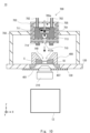
- FIG. 10 is a side cross-sectional view showing a schematic overall configuration of a microscope 10 equipped with a cryogen supply device 700.
- the cryogen supply device 700 is placed on a sample S.
- the cryogen supply device 700 functions as a freezing device for freezing the sample S.
- the basic configuration of the microscope 10 is the same as that of the first and second embodiments, and therefore a description thereof will be omitted as appropriate.
- the configurations of the microscope body 12 and the objective lens 210, etc. can be the same as those used in the first or second embodiment, and therefore a detailed description and illustration thereof will be omitted as appropriate.
- the cryogen supply device 700 includes a cryogen container 705 and a cooling means 703.
- the cryogen container 705 has a storage tank 705a for storing liquid cryogen 701.
- the space inside the cryogen 701 serves as the storage tank 705a for storing the cryogen 701.
- the cryogen container 705 may be an insulated container.
- the bottom surface of the cryogen container 705 is provided with an outlet 710 that releases the cryogen 701 toward the sample S.
- the outlet 710 is provided directly above the field of view 140.
- the cryogen 701 stored in the cryogen container 705 is then released from the outlet 710 toward the sample S in the field of view 140. This allows the sample S to be frozen during or immediately before observation.
- the cryogen supply device 700 is equipped with an on-off valve 713 for opening and closing the discharge port 710.
- the on-off valve 713 is provided in the storage tank 705a so as to be movable in the z direction.
- the on-off valve 713 descends until it comes into contact with the bottom surface of the cryogen container 705, thereby closing the discharge port 710.
- the on-off valve 713 rises and moves away from the bottom surface, thereby opening the discharge port 710.
- the on-off valve 713 may be opened and closed at any time by the user, or the timing of opening and closing may be controlled by various signals.
- An inlet passage 702 for supplying the cryogen 701 material is connected to the cryogen container 705.
- the inlet passage 702 is a pipe attached to the cryogen container 705.
- the cryogen 701 material passes through the inlet passage 702 and is introduced into the storage tank 705a of the cryogen container 705.
- the cryogen 701 material is, for example, a liquid such as isopentane or a gas such as propane.
- two inlet passages 702 are provided in the cryogen container 705. Isopentane is supplied from one inlet passage 702, and propane is supplied from the other inlet passage 702.
- the cryogen material is not limited to these. Also, the cryogen material may be one instead of two.
- the cryogen container 705 is provided with a cooling means 703 for cooling the material of the cryogen 701.
- the cooling means 703 cools the material introduced from the introduction path 702, and the cryogen 701 is generated in the cryogen container 705.
- the cryogen 701 is generated by cooling and liquefying propane in the storage tank 705a.
- the cooling means 703 is liquid nitrogen.
- the cryogen container 705 is a double container, and liquid nitrogen is filled between the inner and outer containers, and more liquid nitrogen is added as needed.
- the cooling means 703 is arranged so as to surround the storage tank 705a.
- the cooling means 703 cools the cryogen material to generate the cryogen 701. Furthermore, the cooling means 703 maintains the cryogen 701 in the cryogen container 705 at a low temperature.
- the cooling means 703 is not limited to liquid nitrogen, and may be a refrigerator having a compressor or the like. In other words, the cooling means 703 may have a refrigerator that cools the cryogen or the container. Furthermore, the cooling means 703 may have both liquid nitrogen and a refrigerator.
- the cryogen container 705 is provided with an agitation mechanism 711.
- the agitation mechanism 711 agitates the cryogen 701 material introduced into the storage tank.
- the agitation mechanism 711 agitates the cryogen 701 material by rotating an agitation blade around an axis.
- the agitation mechanism 711 agitates the cryogen 701 material, thereby enabling efficient production of the cryogen.
- the cryogen supply device 700 functions as a cryogen production device that produces cryogen 701 directly above the sample S.
- the cryogen 701 produced in the cryogen container 705 is released from the release port 710 toward the sample S in the field of view 140. This allows the sample S to be frozen and observed.
- the material of the cryogen 701 may be other substances.
- the cryogen 701 itself may be directly introduced into the cryogen container 705 from the introduction path 702. In other words, the introduction path 702 is provided to introduce the cryogen or its material into the cryogen container 705.
- the cryogen supply device 700 is held by a holder 750.
- the holder 750 is a housing that supports the cryogen container 705.
- the holder 750 holds the cryogen supply device 700 so that the cryogen supply device 700 is disposed above the sample S.
- the holder 750 is attached to the second plate 120, but it may be attached to something other than the second plate 120.
- the holder 750 may be provided separately from the microscope body 12 and its stage part.
- the holder 750 may be fixed to a wall or a pillar in the room in which the microscope 10 is used.
- the cryogen supply device 700 may be provided separately from the microscope 10. In this way, when the cooling means 703 is a refrigerator having a compressor or the like, it is possible to prevent the vibration of the cooling means 703 from being transmitted to the sample S. This allows for stable observation.
- the cryogen container 705 may also be provided with an illumination light source 714.
- the illumination light source 714 is an LED light source or the like, and generates illumination light for illuminating the sample S.
- the illumination light source 714 is a ring light attached to the bottom surface of the cryogen container 705.
- the illumination light source 714 is disposed around the outlet 710. Therefore, the cryogen 701 released from the outlet 710 passes through the hollow portion of the illumination light source 714 and reaches the sample S.
- the sample holder 400 is placed on the second plate 120. Note that the sample holder 400 may be placed between the first plate 110 and the second plate 120, as in the first and second embodiments.
- the sample S is placed on the substrate 401.
- the substrate 401 is fixed on the second plate 120.
- the sample holder 400 holds the sample S on the substrate 401.
- the sample holder 400 has an opening 412a that corresponds to the field of view 140.
- the cryogen 501 released from the release port 710 comes into contact with the sample S through the opening 412a. As a result, the sample S in the field of view 140 is frozen and fixed.
- a portion of the sample S in the sample holder 400 is immersed in a fluid S5.
- the fluid S5 is injected into a holding space surrounded by the sample holder 400.
- the sample holder 400 functions as a wall to hold back the fluid S5.
- the fluid S5 is a buffer solution or culture medium as described in the first embodiment.
- the second plate 120 is provided with a temperature adjustment mechanism 407.
- the temperature adjustment mechanism 407 adjusts the temperature of the sample S and the fluid S5.
- the temperature adjustment mechanism 407 adjusts the temperature of the sample S and the fluid S5 so that they are suitable for acetone replacement.
- the temperature adjustment mechanism 407 has a heater and a cooling mechanism for maintaining a low temperature.
- the temperature adjustment mechanism 407 maintains the sample S and the fluid S5 at a low temperature of about -90°C.
- the temperature adjustment mechanism 407 takes about one day to raise the temperature of the sample S and the fluid S5 to room temperature.
- the temperature adjustment mechanism 407 is in contact with the bottom surface of the sample holder 400, but the position of the temperature adjustment mechanism 407 is not particularly limited.
- the temperature adjustment mechanism 407 may also be used to thaw a frozen sample S.
- the sample holder 400 may be provided with a mechanism for supplying and discharging the fluid S5.
- the configuration of the sample holder 400 capable of supplying or discharging the fluid S5 will be described with reference to FIG. 11.
- FIG. 11 is an enlarged XZ cross-sectional view showing the configuration of the sample holder 400.
- the sample holder 400 is provided with supply pipes 421-423 and discharge pipes 431, 432.
- the supply pipes 421-423 penetrate the side wall of the sample holder 400. Therefore, the supply pipes 421-423 can supply fluid to the sample space G2 inside the sample holder 400.
- the discharge pipes 431, 432 penetrate the side wall of the sample holder 400. Therefore, the supply pipes 421-423 can discharge the fluid S5 in the sample space G2 to the outside.
- acetone is supplied to the sample holder 400 from the supply pipe 421.
- the sample S is replaced with acetone.
- the sample S is dehydrated and chemically fixed.
- Water is supplied to the sample holder 400 from the supply pipe 423.
- the pressure applied to the supply pipe 423 the amount of water in the sample space G2 can be controlled.
- the liquid level of the sample S can be set to the desired height.
- the supply pipe 422 supplies the staining dye and decolorizing agent to the sample holder 400.
- the sample S is stained by supplying the staining dye to the sample space G2 inside the sample holder 400.
- the stained sample S is decolorized by supplying the decolorizing agent to the sample holder 400.
- multiple systems of piping may be provided upstream of the supply pipe 422 so that the decolorizing agent and staining dye supplied to the sample holder 400 can be switched. By switching the staining dye supplied to the sample holder 400, multiple staining can be performed using different fluorescent methods. In this way, the supply pipe 422 can supply chemical solutions such as staining dyes to the sample.
- the exhaust pipes 431 and 432 exhaust the fluid in the sample space G2 to the outside of the sample holder 400.
- the exhaust pipes 431 and 432 are connected to a syringe or the like. By sucking gas with a syringe or the like, the fluid S5 in the sample space G2 can be exhausted to the outside of the sample holder 400.
- a cryogen supply device 700 prepares a cryogen 701 above the sample S. That is, the material of the cryogen 701 is supplied to a cryogen container 705 from an introduction path 702. Then, a cooling means 703 cools the material of the cryogen 701, thereby preparing the cryogen 701 in the cryogen container 705.
- the on-off valve 713 opens and the cryogen 701 is supplied from the outlet 710.
- the timing at which the on-off valve 713 opens may be selected by the user or may be determined by a signal from the sample S or the like.
- the sample S is frozen. The user then observes the frozen sample S. This allows the user to observe the frozen and fixed sample S.
- the sample S is thawed by heating with the temperature control mechanism 407 or by irradiating it with light for thawing.
- the sample S may be observed and then replaced with acetone or the like for fixation.
- the sample S that has been chemically fixed with acetone or the like is then observed. This allows both chemical fixation and freeze fixation to be used for the same sample S.
- the sample S may be thawed by irradiating it with light, for example, and then freeze fixed and observed again. In this manner, fixation and observation of the sample S may be repeated.
- the sample S may also be multi-stained by using multiple fluorescent dyes.
- a cryogen supply device 700 prepares a cryogen 701 above the sample S.
- the cryogen 701 is then supplied from an outlet 710 to freeze the sample S.
- a chemical fixative such as acetone is supplied from a supply pipe 421 to the sample holder 400 to perform chemical fixation.
- the sample S is dehydrated and chemically fixed by acetone replacement.
- the sample S is stained by supplying a staining dye from the supply pipe 422 to the sample holder 400.
- staining can be performed using an antibody or hybridization.
- the staining dye may be used to stain RNA (ribonucleic acid) or proteins, etc., in the sample S. The user then observes the stained sample S.
- the stained sample S is destained by supplying a destaining agent to the sample holder 400 from the supply pipe 422.
- the destaining agent is supplied to the sample space G2 to destain the sample S.
- the staining dye, destaining agent, etc. may be discharged from the discharge pipes 431, 432.
- another staining dye is supplied from the supply pipe 422 into the sample space G2 to stain the sample S.
- the user observes the sample S stained with the other staining dye.
- the sample S is repeatedly stained, observed, and destained.
- a sample image can be obtained in which a variety of molecules are individually stained using various staining dyes.
- various substances in the sample S can be targeted for observation. For example, a fluorescent image in a color according to the fluorescent wavelength can be generated.
- the sample S can be frozen or chemically fixed before observation. The above processing can be performed within the field of view 140. This allows for easy observation.
- FIG. 12 is a diagram for explaining the configuration and operation of the cryogen supply device 700. Note that the configurations other than the cryogen supply device 700 are the same as those in the above embodiment, and therefore descriptions thereof will be omitted as appropriate.
- the sample holder 400 and the microscope body 12 can have the configurations shown in the first to third embodiments.
- FIG. 12 shows the steps of introducing cryogen material, preparing the cryogen, and releasing the cryogen. Note that the sample holder 400 and other components are omitted in the steps of preparing and releasing the cryogen.
- a lid 730 is provided on the discharge port 710 provided on the cryogen container 705.
- the lid 730 is provided so as to cover the discharge port 710 of the cryogen container 705.
- the discharge port 710 is closed by the lid 730 until the cryogen is discharged.
- the lid 730 opens and closes according to the pressure inside the cryogen container 705. For example, the lid 730 opens by increasing the pressure inside the cryogen container 705.
- the cryogen material is introduced into the cryogen container 705 from the introduction path 702.
- a cooling means 703 is provided around the cryogen container 705. Therefore, the cryogen material is cooled in the cryogen container 705, and the cryogen 701 is produced.
- a solid cryogen such as solid nitrogen is produced as the cryogen 701. Therefore, the material of the cryogen 701 can be liquid nitrogen.
- the solid cryogen can also be cooled metal spheres, ice, solid carbon dioxide, etc.
- cryogen 701 When the cryogen 701 is prepared in the cryogen container 705, gas is introduced into the cryogen container 705 through the inlet 702. This pressurizes the cryogen container 705, and the cryogen 701 is pushed out from the outlet 710. In other words, the lid 730 opens and the cryogen 701 falls from the outlet 710. With this configuration, the sample S can be cooled and fixed with the cryogen. Thus, the same effect as above can be obtained. Also, in addition to the inlet 702 in FIG. 12, an outlet for gas or liquid may be provided.
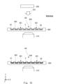
- Fig. 13 is a side cross-sectional view of a sample substrate 800 on which a sample S is placed, and is a diagram for explaining the procedure of the sample freezing method for freezing the sample S.
- the sample S contains a liquid such as a culture solution, and is placed on the sample substrate 800.
- cells S6 are immersed in a fluid S5.
- the fluid S5 is, for example, a culture solution, and the cells S6 are floating cells, cell clumps, or the like.
- the sample substrate 800 is formed with a plurality of grooves 801 for holding the liquid sample S.
- the sample substrate 800 has a plurality of convex portions 804 and a plurality of concave portions 805.
- the convex portions 804 and concave portions 805 are repeatedly formed in the X direction.
- the concave portions 805 become the grooves 801 for holding the liquid sample S.
- the sample substrate 800 is formed from a transparent material such as quartz.
- the grooves 801 extend in the Y direction, which is perpendicular to the paper surface.
- a number of grooves 801 are arranged side by side in the X direction.
- the depth of the grooves 801 is 50 ⁇ m to 100 ⁇ m.
- the width of the grooves 801 is 100 ⁇ m to 300 ⁇ m.
- the depth and width of the grooves 801 are not limited to the above values, and may be any size that can hold cells, etc.
- all of the grooves 801 in FIG. 13 have the same depth and width, they may be of different sizes.
- the planar shape of the unevenness may be a slit array, a hole array, or a mesh shape.
- a slit array having a number of grooves lined up in a row may be provided on the sample substrate 800.
- a hole array having a number of holes arranged two-dimensionally in the X and Y directions may be provided on the sample substrate 800.
- mesh-like recesses having a number of grooves formed in both the X and Y directions may be provided.
- the multiple recesses 805 may be partially connected. In this case, the height of the fluid S5 in the multiple recesses 805 can be made uniform.
- the bottom surface of the recess 805 may have a hole for passing the fluid S5. By having a hole in the bottom surface, the amount of the fluid S5 can be reduced.
- the material of the sample substrate 800 is not limited to quartz, and may be a flexible material such as resin.
- a method for freezing the sample S will be described. First, a sample substrate 800 having a plurality of recesses 805 is prepared. A liquid sample S is placed in the plurality of recesses 805 on the sample substrate 800. The fluid S5 contains a plurality of cells.
- the fluid S5 on top of the sample substrate 800 is removed.
- a portion of the fluid S5 in the groove 801 is removed.
- the amount of fluid S5 in the groove 801 can be reduced.
- the amount of liquid may be reduced by vaporizing or evaporating the fluid S5.
- the amount of liquid may be reduced by sucking in the fluid S5.
- the cell S6 is held in the groove 801.
- a cryogen is supplied to the sample S to freeze the sample S.
- a cryogen supply device 500 is provided above the sample substrate 800.
- the cryogen supply device 500 releases a cryogen toward the sample substrate 800.
- a frozen sample S7 in which the cells S6 and fluid S5 are frozen is formed in the groove 801.
- the cryogen is supplied from above.
- the cryogen may be liquid or solid.
- a sample substrate 800 with an uneven surface is prepared.
- a cell or a group of cells is placed in the recessed portion.
- the thickness of the solution near the cells can be made to be several tens to several hundreds of ⁇ m.
- a liquid or solid cryogen is brought into contact with the cells from above. In this way, the cells can be rapidly frozen.
- the frozen sample S7 may be observed as in the first to third embodiments.
- FIG. 14 is a side cross-sectional view showing the procedure for thawing a frozen sample S7.
- the frozen sample S7 is thawed by contacting a heat source 810 with the back or side of the sample substrate 800.
- the heat source 810 may be a solution or a solid.
- the sample substrate 800 or the frozen sample S7 is heated by the heat source 810 to thaw the frozen sample S7.
- the entire sample substrate 800 or a part of it may be made of or coated with metal. By contacting the heat source 810 with the metal portion, thawing can be performed more quickly.
- Frozen sample S7 may be thawed by irradiating it with laser light, microwaves, etc.
- the method of thawing frozen sample S7 is not particularly limited.
- a culture medium or the like is added to the thawed sample S to culture cells S6. This allows cells S6 contained in the sample S that was once frozen to be cultured again.
- Cell damage during freezing and thawing can be suppressed.
- the amount of liquid around the cells can be reduced while the cells are still placed on the sample substrate 800.
- the cells are frozen by contacting them with a cryogen while keeping the amount of liquid low.
- the speed of cell freezing is improved and the probability of ice crystal formation can be significantly reduced.
- the amount of liquid is small, so cells can be thawed quickly. This makes it possible to prevent ice crystal formation during thawing.
- the frozen cells are plate-shaped and their volume is smaller than when they are stored in conventional solutions. This makes it possible to store many cells in a small storage volume and makes temperature control easier.
- the sample substrate 800 may be placed on the stage of the microscope 10.
- a cryogen is supplied to the sample substrate 800 placed on the stage. This allows the cells S6 to be frozen in the field of view of the microscope 10, making it possible to observe the state of the sample S as it freezes. In other words, the user can observe the state of the cells S6 freezing.
- Figure 15 is a side cross-sectional view showing how to observe sample S while it is being frozen.
- a sample substrate 800 is placed in the field of view 140 of the objective lens 210.
- the objective lens 210 is placed directly below the sample substrate 800.
- a cryogen 501 is supplied from above to the sample S in the field of view 140. This causes the sample S to freeze, forming a frozen sample S7. The user can observe the state of the sample S while it is freezing.
- the state of the sample S during thawing can be observed under a microscope by contacting the heat source 810 on the microscope.
- the sample can also be re-frozen by removing the heat source 810. This allows the sample S to be repeatedly frozen and thawed while the state of the sample S during this process can be observed under a microscope. It is easy to observe cells under a microscope while they are frozen, stored, and thawed. Cryo-optical observation, evaluation of frozen cells, and observation of cells during/after thawing can be performed.
- quartz substrate for the sample substrate 800. This reduces distortion of the sample substrate 800 caused by temperature changes, and prevents blurring or shifting of the observed image when freezing during microscopic observation.
- fluid S5 contains a metal colloid such as gold colloid or metal particles.
- the cryogen may also contain a metal colloid such as gold colloid or metal particles. This can improve cooling and thawing efficiency.
- the frozen sample can be stored at a low temperature by placing each sample substrate in a cryogen or in contact with a cooled solid.
- fluid S5 and the cryogen may contain fine particles such as dielectric nanoparticles whose volume decreases when cooled. This can reduce the increase in volume of fluid S5 due to ice crystal formation even if ice crystals are formed in fluid S5, and suppress deformation of the sample due to freezing.
- FIG 17 shows a plan view and a cross-sectional view of a sample substrate 800 provided with a reservoir.
- the sample substrate 800 has a number of grooves 801.
- Each groove 801 extends in the Y direction.
- the grooves 801 are connected to a reservoir 807.
- a groove 808 extends in the X direction from the reservoir 807.
- the groove 808 is a recess extending in the X direction.
- the three grooves 801 are connected by the groove 808. In other words, the groove 808 intersects with the groove 801.
- the reservoir 807 has a sufficiently larger area than the grooves 801 and 808. This makes it possible to prevent a decrease in the amount of liquid in the groove 801 due to evaporation of the liquid. This allows for stable freezing, storage, or observation. Furthermore, a cover may be provided on the sample substrate 800 to prevent a decrease in the amount of liquid due to evaporation.
- the cover is provided so as to cover, for example, the reservoir 807, the groove 801, or the groove 808. Of course, the cover may cover only a portion of the reservoir 807, etc.
- Figure 18 is a YZ cross-sectional view showing the configuration of the sample holder 400.
- Figures 19 and 20 are cross-sectional perspective views of the sample holder 400.
- Figure 19 shows the configuration before the liquid volume is adjusted, and
- Figure 20 shows the configuration after the liquid volume is adjusted.
- the sample holder 400 comprises an upper holder 462 and a lower holder 461.
- the upper holder 462 is disposed above the sample substrate 800.
- the lower holder 461 is disposed below the sample substrate 800.
- the sample substrate 800 is disposed between the upper holder 462 and the lower holder 461.
- the upper holder 462 and the lower holder 461 are each a plate-shaped member, and are disposed so as to face each other.
- the lower holder 461 is formed with an objective lens space G1 for placing an objective lens (not shown).
- the upper holder 462 is formed with a sample holder 412.
- the sample holder 412 is in contact with the liquid S1 outside the field of view 140.
- An opening 412a is provided in the sample holder 412.
- a cryogen is supplied from the upper side of the upper holder 462. Therefore, the cryogen comes into contact with the sample S through the opening 412a.
- a suction port 463 is formed on the side of the upper holder 462.
- the suction port 463 is a through hole that penetrates the upper holder 462 and extends in the Y direction.
- the suction port 463 is connected to a syringe or the like provided on the outside of the sample holder 400.
- the height of the liquid surface can be adjusted by sucking the fluid S5 from the suction port 463. In other words, the amount of liquid can be reduced by sucking the fluid S5 from the suction port 463. By reducing the amount of liquid, the sample S can be frozen in a short time after the cryogen is supplied.
- the thickness of the remaining solution can be made to be several tens of ⁇ m to several hundreds of ⁇ m. In this way, the sample S can be frozen quickly and reproducibly by supplying a cryogen.
- the sample S is a cell or the like, and is held in the groove 801 in the same manner as in the fourth embodiment.
- the width of the groove 801 can be made sufficiently large so that the thickness of the remaining solution only in the observation area at the center of the groove 801 is made to be several tens of ⁇ m to several hundreds of ⁇ m, and the thickness of the remaining solution near the side wall surface of the groove 801 can be made thicker than that of the observation area at the center. In this way, the reduction in the amount of liquid in the observation area due to evaporation can be more efficiently suppressed.
- a sample S containing a sufficient amount of fluid S5 is placed on the sample holder 400.
- the amount of fluid S5 that overflows from the groove 801 may be dripped onto the sample substrate 800.
- the fluid S5 is sucked from the suction port 463.
- the amount of liquid decreases, and the liquid level becomes lower.
- the surface of the sample substrate 800 is exposed except for the groove 801, etc.
- a cryogen is supplied from the opening 412a. This brings the cryogen into contact with the sample S, and the sample S can be frozen. In this way, the amount of liquid is reduced, and the sample S can be frozen quickly. Then, the frozen sample is observed in the field of view 140.
- the fluid S5 is discharged from the suction port 463 provided along the Y direction. Therefore, the liquid level is lowest at the end side in the Y direction. In the vicinity of the suction port 463, the fluid S5 on the sample substrate 800 is completely sucked up. On the other hand, at the end side in the X direction, the fluid S5 on the sample substrate 800 is not completely sucked up, so the liquid level is higher.
- Fig. 21 is a cross-sectional view showing a schematic configuration of a sample holder 900.
- the configuration of the microscope is omitted as appropriate.
- the objective lens below the sample S is omitted.
- the configuration of the sample holder for maintaining the sample S at a low temperature will be described with reference to Fig. 21.
- the sample holder 900 includes a substrate 401, an upper holder 910, a metal plate 913, and a lower holder 915.
- a sample S is placed on the substrate 401.
- a cryogen for freezing is supplied to the sample S.
- the substrate 401 is held between an upper holder 910 and a lower holder 915.
- the peripheral portion of the substrate 401 is disposed between the upper holder 910 and the lower holder 915.
- the upper holder 910 is provided with a cryogen tank 912 that stores a cryogen 920 for maintaining a low temperature.
- the cryogen tank 912 stores a cryogen 920 such as liquid nitrogen.
- the cryogen tank 912 is disposed outside the field of view 140.
- the upper holder 910 and the lower holder 915 are formed from a heat insulating material. This makes it possible to suppress a rise in the temperature of the cryogen 920.
- a metal plate 913 is fixed to the lower holder 915.
- the metal plate 913 is arranged so as to be in contact with the cryogen 920.
- the metal plate 913 forms the bottom surface of the cryogen storage tank 912.
- the upper holder 910 forms the side surface of the cryogen storage tank 912.
- the space formed by the upper holder 910 and the metal plate 913 forms the cryogen storage tank 912.
- the metal plate 913 is cooled by the cryogen 920. Therefore, the metal plate 913 is maintained at a low temperature.
- the metal plate 913 is a heat transfer member with high thermal conductivity.
- the metal plate 913 is in contact with the substrate 401.
- the metal plate 913 extends outward from the peripheral portion of the substrate 401.
- the metal plate 913 cooled by the cryogen 920, maintains the substrate 401 and the sample S at a low temperature. In this way, the temperature rise of the sample S can be further suppressed. This makes it possible to maintain a low temperature state for a long period of time, allowing the frozen sample S to be observed for a long period of time.
- a temperature measurement mechanism using a thermocouple or the like may be provided. Also, in order to remove the freezing agent dropped onto the sample S and to prevent condensation, the sample S may be observed in an inert gas atmosphere such as nitrogen gas around the sample S. This allows the sample S to be observed with an objective lens from either the top or bottom side of the sample S.
- Fig. 22 is an exploded perspective view showing the configuration of the sample holder 400 having a cooling block.
- Fig. 23 is a perspective view showing the cross-sectional configuration of the sample holder 400.
- the sample holder 400 holds the cooling block 460 together with the substrate 401.
- the sample holder 400 comprises a lower holder 461 and an upper holder 462.
- the lower holder 461 and the upper holder 462 are fixed with bolts 468.
- a cooling block 460 is attached to the upper holder 462.
- the substrate 401 and the cooling block 460 are then disposed between the upper holder 462 and the lower holder 461.
- the lower holder 461 and the upper holder 462 may also be connected with a hinge-like mechanism to fix the lower holder 461 and the upper holder 462 together. This makes it easier to open and close the lower holder 461 and the upper holder 462.
- the cooling block 460 is disposed above the substrate 401.
- a ring-shaped spacer 466 is provided between the cooling block 460 and the substrate 401.
- a sample stage 473 with an opening is provided below the substrate 401 to support the substrate 401.
- the substrate 401 is pressed against the spacer 466 by the sample stage 473 with an opening, and is disposed facing the cooling block 460 via the spacer 466.
- a sample containing liquid is disposed in the space surrounded by the spacer 466 on the substrate 401.
- the sample on the substrate 401 can be observed with the objective lens 210 through the opening of the sample stage 473 with an opening.
- the portion of the sample stage 473 with an opening that supports the substrate 401 may be equipped with a mechanism such as a spring.
- the lower holder 461, the upper holder 462, the cooling block 460, the sample stage with opening 473, and the spacer 466 may be provided with an opening for reducing the amount of fluid on the substrate 401 as described in Figs. 18 to 20.
- a cooling pipe for circulating liquid nitrogen in the sample stage with opening 473, a temperature measurement mechanism using a thermocouple, or a heater may be provided to control the temperature of the space below the substrate 401. This can improve the temperature stability of the sample on the substrate 401.
- the sample stage with opening 473 may also be provided with a circulation mechanism for supplying and discharging a solution such as an organic solvent that is difficult to freeze to the space between the substrate 401 and the objective lens 210. This allows a solution that is not frozen to be placed in the space between the substrate 401 and the objective lens 210, making it possible to use an immersion objective lens with a high numerical aperture for observation.
- the side of the upper holder 462 is provided with a gas inlet 469 for supplying an inert gas to prevent condensation on the objective lens 210.
- the upper holder 462 has a cryogen supply port 462a.
- the cryogen supply port 462a is, for example, a through hole provided along the Z direction. Alternatively, the cryogen supply port 462a may be a screw hole for fixing a cover or an optical window, which will be described later.
- a cryogen introduction unit 480 is provided above the cryogen supply port 462a.
- the cryogen introduction unit 480 is a cylindrical member and has a cryogen inlet 481.
- the cryogen from the cryogen inlet 481 is supplied to the sample through the cryogen supply port 462a.
- a liquid nitrogen storage tank 482 is formed around the cryogen inlet 481.
- the liquid nitrogen storage tank 482 stores liquid nitrogen for pre-cooling. This prevents the cryogen from touching the cryogen introduction unit 480 before touching the sample, causing a rise in temperature.
- the cooling block 460 is formed from a material with high thermal conductivity, such as a metal material such as aluminum, copper, or silver.
- the cooling block 460 is provided with a cooling pipe 460b through which liquid nitrogen circulates.
- the cooling pipe 460b serves as a flow path that passes through the inside of the cooling block 460.
- a liquid nitrogen supply port 464 and a liquid nitrogen discharge port 465 are provided on the side of the upper holder 462.
- the supply port 464 and the discharge port 465 are connected to the cooling pipe 460b.
- the liquid nitrogen supplied from the supply port 464 circulates inside the cooling block 460 and is discharged from the discharge port 465.
- the cooling block 460 is also provided with a thermocouple and heater for temperature control. Terminals 460c of the thermocouple and heater are provided on the side of the cooling block 460.
- a port 467 is provided on the side of the upper holder 462 for connecting to a temperature sensor such as a thermocouple or a heater. Current is supplied to the heater from the port 467. A voltage signal of the thermocouple is also taken out from the port 467.
- the cooling block 460 has a through hole 460a along the Z direction.
- the through hole 460a is provided in the field of view of the objective lens 210.
- the through hole 460a is located directly below the cryogen supply port 462a.
- the cryogen from the cryogen inlet 481 is supplied to the sample through the through hole 460a.
- the sample can be maintained at a low temperature.
- the cooling block 460 comes into contact with the cryogen, so the cryogen is maintained at a low temperature.
- the cooling block 460 is provided with a heater and a temperature sensor for adjusting the temperature. In this way, the temperature of the sample can be controlled. It is possible to easily observe the sample in a frozen state or after thawing.
- the cryogen can be removed and the temperature of the sample can be controlled using only the cooling block 460.
- the cryogen introduction unit 480 is removed and the cryogen supply port 462a is closed with a lid or the like to seal the storage space.
- the lid that closes the cryogen supply port 462a an optical window made of a transparent substrate such as glass, illumination light can be introduced from the top of the cryogen supply port 462a to allow observation of the sample.
- the sample to be observed may be adherent cells, floating cells, cell clumps, or cell-derived substances such as exosomes, RNA (ribonucleic acid), or DNA (deoxyribonucleic acid).
- the material of the substrate that holds the sample may be water-soluble. In this way, simply by placing the substrate containing the sample, such as frozen cells, in a liquid such as culture medium, the substrate will dissolve and the sample can be separated from the substrate, and can be used as is for sample observation, culturing, etc.
- the holder surface in the area through which the cryogen passes may be coated with a highly insulating material or covered with a member made of a highly insulating material. This can prevent the temperature rise of the cryogen during dripping and the associated bumping, improving the reproducibility of the sample freezing speed.
- (Appendix 1) a sample holder for holding a sample including a liquid, the volume of the liquid in a cryogen contact area being different from the volume of the liquid outside the cryogen contact area; and a sample freezing means for freezing the sample in the cryogen contact area by a cryogen.
- Appendix 2 2. The freezing apparatus of claim 1, wherein the sample holder holds the sample in a state where the liquid level of the sample in the cryogen contact area is lower than outside the cryogen contact area.
- (Appendix 3) 3. The freezing device according to claim 1, further comprising an adjustment mechanism for adjusting a liquid level of the liquid.
- the sample holder is provided with a through hole, The freezing device according to any one of claims 1 to 3, wherein the liquid level of the liquid is adjusted by sucking the liquid through the through hole.
- (Appendix 5) a first supply port through which a chemical fixing agent for chemically fixing the sample is supplied to a space surrounded by the sample holder;
- the sample holder is provided with a sample holder for holding the sample, 6.
- (Appendix 7) The freezing device according to claim 1, wherein a liquid level of the liquid is adjusted by pressing a pressing member provided on the sample against the sample.
- (Appendix 8) 7.
- (Appendix 9) The freezing device according to any one of claims 1 to 8, further comprising a measurement mechanism for measuring a liquid level of the liquid.
- (Appendix 10) 10.
- (Appendix 11) 11.
- (Appendix 12) a cryogen container disposed above the sample and having an outlet for releasing a cryogen toward the sample; an introduction path for a cryogen or a material thereof for the cryogen container;
- the freezing device according to any one of claims 1 to 11, further comprising: a cooling means provided in the cryogen container for cooling the cryogen or a material thereof.
- the cooling means comprises a refrigerator or liquid nitrogen.
- (Appendix 14) 14 14.
- the freezing device according to any one of claims 1 to 18, wherein the sample is held on a sample freezing substrate having an uneven surface.
- Appendix 20 20.
- Appendix 21 21.
- Appendix 22 22.
- the freezing device according to any one of claims 19 to 21, wherein a reservoir for storing a fluid is formed in the sample freezing substrate.
- Appendix 23 When viewed from above, the reservoir is formed at an end of the sample freezing substrate in a first direction, 23.
- a freezing device according to any one of claims 1 to 11, an objective lens that receives light from the sample; the cryogen contact area corresponds to a field of view of the objective lens; A microscope in which the sample freezing means freezes a sample in the field of view of the objective lens.
- Appendix 25 Further comprising a cooling block disposed directly above the sample; a cooling pipe for circulating a liquid for cooling the cooling block is provided inside the cooling block, 25.
- Appendix 26 26.
- Appendix 27 a sample holder holding a sample including liquid, with a volume of the liquid of the sample in a cryogen contact area being different from a volume of the liquid outside the cryogen contact area; and freezing the sample in the cryogen contact area with a cryogen.
- (Appendix 32) 32 The freezing device according to any one of claims 28 to 31, wherein the cryogen container is provided with an agitator that agitates the cryogen materials to generate the cryogen.
- (Appendix 33) 33 The freezing device according to any one of claims 28 to 32, wherein the discharge port is provided with an on-off valve.
- (Appendix 34) 34 The freezing apparatus according to claim 33, wherein the on-off valve is controlled to open and close by a signal from the sample or a signal for stimulating the sample.
- (Appendix 35) 35 The freezing device according to any one of claims 28 to 34, wherein the sample is held on a sample freezing substrate having an uneven surface. (Appendix 36) 36.
- the freezing device according to claim 35 wherein the depth of the concave portions of the unevenness is 50 ⁇ m to 100 ⁇ m.
- the reservoir is formed at an end of the sample freezing substrate in a first direction, 39.
- the freezing apparatus according to claim 38 wherein a suction port for sucking the liquid is formed at an end of the sample holder in a second direction perpendicular to the first direction.
- Appendix 40 A freezing device according to any one of appendices 28 to 39, a sample holder provided to surround the sample and having an opening to which the cryogen discharged from the discharge port is supplied; a stage on which the sample holder is placed; a microscope having an objective lens disposed below the stage for observing the sample frozen with the cryogen.
- Appendix 41 41.
- the microscope of claim 40 further comprising a temperature adjustment mechanism for adjusting a temperature of the sample.
- the sample holder includes: a first supply port through which a chemical fixing agent for chemically fixing the sample is supplied to a space surrounded by the sample holder; 42.
- the microscope according to claim 40 or 41 further comprising: a second supply port for supplying a staining dye for staining the sample or a decolorizing agent for decolorizing the stained sample to the space.
- a cooling block disposed over the specimen; the cooling block is provided with a cooling pipe through which a cooling liquid for cooling the sample circulates; 43.
- Appendix 44 44.
- (Appendix 45) 45 The microscope according to claim 44, wherein the cooling block is provided with a heater for heating a sample.
- Appendix 46 (1) supplying a cryogen to a sample in the field of view of a microscope to freeze the sample; (2) providing a chemical fixative to the frozen sample to chemically fix the sample; (3) supplying a staining dye to the chemically fixed sample to stain it; (4) An observation method comprising the step of observing the stained sample with the microscope. (Appendix 47) (5) after observation, supplying a decolorizing agent to the sample in the field of view; (6) The observation method according to claim 46, further comprising a step of supplying another staining dye to the destained sample to stain the sample.
- Appendix 48 A sample of a fluid containing cells is placed in a plurality of recesses provided on a sample freezing substrate; A freezing method in which a cryogen is supplied to freeze the sample placed in the recess. (Appendix 49) 49. The freezing method according to claim 48, wherein the depth of the recess is 50 ⁇ m to 100 ⁇ m. (Appendix 50) 50. The freezing method according to claim 48 or 49, wherein the width of the recess is 100 ⁇ m to 300 ⁇ m. (Appendix 51) 51. The freezing method according to any one of claims 48 to 50, wherein the sample is frozen by contacting the sample with a cryogen while the sample freezing substrate is in the field of view of a microscope. (Appendix 52) 52.
- a sample freezing substrate for freezing a sample using a cryogen A sample freezing substrate with a surface formed with projections and recesses for holding a sample of a fluid containing cells.
- Appendix 54 54.
- the sample freezing substrate according to claim 53, wherein the depth of the concave portions of the unevenness is 50 ⁇ m to 100 ⁇ m.
- Appendix 55 55.
- Appendix 56 56.
- Appendix 57 A sample freezing substrate according to any one of claims 53 to 55, a cryogen container disposed above the sample freezing substrate and having an outlet for releasing a cryogen toward the sample.
- Appendix 58 58.
- Appendix 60 60.
- the microscope of claim 59 wherein the sample is thawed using a heat source.
- Appendix 61 holding a cooling block positioned over the sample;
- the cooling block is provided with a through hole through which the cryogen passes, 61.
- the microscope according to any one of appendices 59 to 60, wherein the cooling block is provided with a heater and a temperature sensor for adjusting temperature.
- Appendix 63 A sample holder for holding a sample including a liquid; A sample freezing means for freezing the sample by a cryogen, A freezing device that adjusts the height of the liquid by sucking the liquid through a through hole provided in the sample holder.
- the freezing apparatus according to claim 63 or 64, wherein the sample freezing means comprises a cryogen container disposed above the sample and having an outlet for releasing a cryogen toward the sample.
- the sample freezing means an introduction path for a cryogen or a material thereof for the cryogen container; 66.
- the freezing device of claim 65 further comprising: a cooling means provided in the cryogen container for cooling the cryogen or a material thereof.
- Appendix 67 67.
- the freezing device according to any one of claims 63 to 66, wherein the sample holder holds a sample freezing substrate having a surface formed with irregularities for holding a fluid sample containing cells.
- Appendix 68 68.
- the freezing device according to claim 67 wherein the depth of the concave portions of the unevenness is 50 ⁇ m to 100 ⁇ m.
- (Appendix 69) 69.
- the freezing apparatus of claim 63 wherein the sample holder holds the sample in a state where a liquid level of the sample in the cryogen contact area is lower than outside the cryogen contact area.
- Appendix 71 Further comprising a cooling block disposed directly above the sample; a cooling pipe for circulating a liquid for cooling the cooling block is provided inside the cooling block, 71.
- the freezing device of claim 70 further comprising a through hole through which a cryogen passes for freezing the sample.
- Appendix 72 72.
- Appendix 73 73.
- Appendix 74 A freezing device according to any one of appendices 62 to 73, A microscope having an objective lens that receives light from the sample.
- Appendix 75 an objective lens that receives light from the sample; a sample freezing means for supplying a cryogen to a sample in the field of view of the objective lens to freeze the sample;
- a microscope comprising a cooling block disposed directly above the sample for cooling the sample or the cryogen, the cooling block having through holes through which the cryogen passes.
- Appendix 76 76.
- the microscope according to claim 75 wherein a cooling pipe for circulating a liquid for cooling the cooling block is provided inside the cooling block.
- Appendix 77 77.
- Appendix 78 78.
- Appendix 79 Freezing the sample in the field of view of the objective by the method of claim 27, 49, 50, 51, or 52; and observing the frozen sample in the cryogen contact area using the objective lens.
- Appendix 80 80. The observation method of claim 79, further comprising observing the sample while the sample is frozen by the cryogen.
Landscapes
- Physics & Mathematics (AREA)
- Chemical & Material Sciences (AREA)
- Life Sciences & Earth Sciences (AREA)
- Health & Medical Sciences (AREA)
- General Physics & Mathematics (AREA)
- Analytical Chemistry (AREA)
- Engineering & Computer Science (AREA)
- Optics & Photonics (AREA)
- Wood Science & Technology (AREA)
- General Health & Medical Sciences (AREA)
- Biochemistry (AREA)
- Organic Chemistry (AREA)
- Zoology (AREA)
- Bioinformatics & Cheminformatics (AREA)
- Molecular Biology (AREA)
- Biomedical Technology (AREA)
- Sustainable Development (AREA)
- Microbiology (AREA)
- Biotechnology (AREA)
- Pathology (AREA)
- General Engineering & Computer Science (AREA)
- Genetics & Genomics (AREA)
- Immunology (AREA)
- Sampling And Sample Adjustment (AREA)
- Microscoopes, Condenser (AREA)
Priority Applications (3)
| Application Number | Priority Date | Filing Date | Title |
|---|---|---|---|
| CN202380081812.0A CN120265969A (zh) | 2022-11-29 | 2023-10-27 | 冷冻装置、显微镜、冷冻方法、以及观察方法 |
| EP23897337.4A EP4628868A4 (en) | 2022-11-29 | 2023-10-27 | FREEZING DEVICE, MICROSCOPE, FREEZING METHOD AND OBSERVATION METHOD |
| JP2024561262A JPWO2024116681A1 (https=) | 2022-11-29 | 2023-10-27 |
Applications Claiming Priority (4)
| Application Number | Priority Date | Filing Date | Title |
|---|---|---|---|
| JP2022-189880 | 2022-11-29 | ||
| JP2022189880 | 2022-11-29 | ||
| JP2023-122175 | 2023-07-27 | ||
| JP2023122175 | 2023-07-27 |
Publications (1)
| Publication Number | Publication Date |
|---|---|
| WO2024116681A1 true WO2024116681A1 (ja) | 2024-06-06 |
Family
ID=91323729
Family Applications (1)
| Application Number | Title | Priority Date | Filing Date |
|---|---|---|---|
| PCT/JP2023/038854 Ceased WO2024116681A1 (ja) | 2022-11-29 | 2023-10-27 | 凍結装置、顕微鏡、凍結方法、及び観察方法 |
Country Status (4)
| Country | Link |
|---|---|
| EP (1) | EP4628868A4 (https=) |
| JP (1) | JPWO2024116681A1 (https=) |
| CN (1) | CN120265969A (https=) |
| WO (1) | WO2024116681A1 (https=) |
Citations (9)
| Publication number | Priority date | Publication date | Assignee | Title |
|---|---|---|---|---|
| JPS59218417A (ja) * | 1983-05-25 | 1984-12-08 | Osaka Oxgen Ind Ltd | 極低温検鏡法およびそれに用いる顕微鏡 |
| JPS61263037A (ja) * | 1985-05-16 | 1986-11-21 | Univ Kyoto | 凍結試料交換装置 |
| JPH034247U (https=) * | 1989-06-02 | 1991-01-17 | ||
| JPH03134527A (ja) * | 1989-10-19 | 1991-06-07 | Osaka Gas Co Ltd | 極微小量の試料の温度測定装置 |
| JP2007080517A (ja) * | 2005-09-09 | 2007-03-29 | Jeol Ltd | 電子顕微鏡用クライオステージ |
| JP2015068832A (ja) * | 2013-09-30 | 2015-04-13 | エフ イー アイ カンパニFei Company | 荷電粒子顕微鏡用の極低温試料の調製 |
| US20180058990A1 (en) * | 2016-08-26 | 2018-03-01 | Simple Origin, Inc. | System and method for refilling cryogen in microscope cryogen holders |
| JP2022189880A (ja) | 2014-05-29 | 2022-12-22 | パナソニック インテレクチュアル プロパティ コーポレーション オブ アメリカ | 複数の機器を遠隔制御する端末装置の制御方法及び端末装置が実行するプログラム |
| JP2023122175A (ja) | 2022-02-22 | 2023-09-01 | Jfe建材株式会社 | デッキプレートの製造方法 |
Family Cites Families (5)
| Publication number | Priority date | Publication date | Assignee | Title |
|---|---|---|---|---|
| GB0420657D0 (en) * | 2004-09-16 | 2004-10-20 | Thermo Shandon Ltd | Cryostat and microtome |
| DE102012013267A1 (de) * | 2012-07-04 | 2014-01-09 | Fraunhofer-Gesellschaft zur Förderung der angewandten Forschung e.V. | Substrateinrichtung, Konservierungsgerät und Verfahren zur Kryokonservierung einer biologischen Probe |
| EP3179229B1 (en) * | 2015-12-11 | 2019-01-30 | FEI Company | Preparation of cryogenic sample for charged-particle microscopy |
| US20240201056A1 (en) * | 2021-04-27 | 2024-06-20 | MAX-PLANCK-Gesellschaft zur Förderung der Wissenschaften e.V. | Method and device for ultra-rapid cryo-fixation of a sample for microscopic studies |
| CN117642669A (zh) * | 2021-05-12 | 2024-03-01 | 国立大学法人大阪大学 | 显微镜和观察方法 |
-
2023
- 2023-10-27 JP JP2024561262A patent/JPWO2024116681A1/ja active Pending
- 2023-10-27 CN CN202380081812.0A patent/CN120265969A/zh active Pending
- 2023-10-27 WO PCT/JP2023/038854 patent/WO2024116681A1/ja not_active Ceased
- 2023-10-27 EP EP23897337.4A patent/EP4628868A4/en active Pending
Patent Citations (9)
| Publication number | Priority date | Publication date | Assignee | Title |
|---|---|---|---|---|
| JPS59218417A (ja) * | 1983-05-25 | 1984-12-08 | Osaka Oxgen Ind Ltd | 極低温検鏡法およびそれに用いる顕微鏡 |
| JPS61263037A (ja) * | 1985-05-16 | 1986-11-21 | Univ Kyoto | 凍結試料交換装置 |
| JPH034247U (https=) * | 1989-06-02 | 1991-01-17 | ||
| JPH03134527A (ja) * | 1989-10-19 | 1991-06-07 | Osaka Gas Co Ltd | 極微小量の試料の温度測定装置 |
| JP2007080517A (ja) * | 2005-09-09 | 2007-03-29 | Jeol Ltd | 電子顕微鏡用クライオステージ |
| JP2015068832A (ja) * | 2013-09-30 | 2015-04-13 | エフ イー アイ カンパニFei Company | 荷電粒子顕微鏡用の極低温試料の調製 |
| JP2022189880A (ja) | 2014-05-29 | 2022-12-22 | パナソニック インテレクチュアル プロパティ コーポレーション オブ アメリカ | 複数の機器を遠隔制御する端末装置の制御方法及び端末装置が実行するプログラム |
| US20180058990A1 (en) * | 2016-08-26 | 2018-03-01 | Simple Origin, Inc. | System and method for refilling cryogen in microscope cryogen holders |
| JP2023122175A (ja) | 2022-02-22 | 2023-09-01 | Jfe建材株式会社 | デッキプレートの製造方法 |
Non-Patent Citations (3)
| Title |
|---|
| FUEST ET AL., J. MICROSCOPY., vol. 272, 2018, pages 87 |
| HUEBINGER ET AL., SCIENCE ADVANCED, vol. 7, 2021, pages 0882 |
| See also references of EP4628868A4 |
Also Published As
| Publication number | Publication date |
|---|---|
| CN120265969A (zh) | 2025-07-04 |
| EP4628868A1 (en) | 2025-10-08 |
| EP4628868A4 (en) | 2026-04-01 |
| JPWO2024116681A1 (https=) | 2024-06-06 |
Similar Documents
| Publication | Publication Date | Title |
|---|---|---|
| US20240210291A1 (en) | Microscope and observation method | |
| TWI401472B (zh) | 顯微鏡裝置及使用該顯微鏡裝置的螢光觀察方法 | |
| US20090311717A1 (en) | Microfluidic chip design comprising capillaries | |
| CN110062880B (zh) | 通过受控样品蒸发制备无损冷冻载网 | |
| US8969075B2 (en) | Method and apparatus for preparing cells for microtome sectioning and archiving nucleic acids and proteins | |
| Okolo et al. | Sample preparation strategies for efficient correlation of 3D SIM and soft X-ray tomography data at cryogenic temperatures | |
| JP6513802B2 (ja) | ナノ粒子検出のためのレーザー光結合 | |
| US20080131922A1 (en) | Cell culture detection apparatus, cell culture observation apparatus, and cell culture observation method | |
| JP2013164419A (ja) | 電子顕微鏡用のガラス化された試料を作製する方法 | |
| WO2019178121A1 (en) | Method and apparatus for temperature gradient microfluidics | |
| WO2024109896A1 (zh) | 一种基于微流控芯片细胞培养的快速控温装置 | |
| Yuan et al. | A flexible chamber for time-lapse live-cell imaging with stimulated raman scattering microscopy | |
| CN113227391A (zh) | 激光诱导的细胞转移和分选 | |
| JP2023140768A (ja) | 試料測定装置、試料測定システム及び人工授精装置 | |
| US10385305B2 (en) | Device for measuring activity of cultured cells, microchamber and method of measuring activity of cultured cells | |
| WO2024116681A1 (ja) | 凍結装置、顕微鏡、凍結方法、及び観察方法 | |
| US8278629B2 (en) | Observation chamber for studying temperature-dependent events and method thereof | |
| KR101665057B1 (ko) | 스프링 타입 초저온 샘플 플런저 장치 및 이를 이용한 시료 그리드의 냉각방법 | |
| EP4083597A1 (en) | Method and device for ultra-rapid cryo-fixation of a sample for microscopic studies | |
| US20240201056A1 (en) | Method and device for ultra-rapid cryo-fixation of a sample for microscopic studies | |
| KR20160016399A (ko) | 광학현미경과 전자현미경의 연계형 이미징 검출을 위해 초저온 전자현미경 시편장착 홀더를 포함하는 워크 스테이션 또는 이를 포함한 연계형 이미징 검출장치를 이용한 연계형 현미경 관찰 방법 | |
| US7852554B2 (en) | Cryogenic immersion microscope | |
| CN113720842B (zh) | 一种生物样品成像辅助装置、生物样品成像系统及方法 | |
| CN111108426A (zh) | 低温光显微镜和用于低温光显微术的浸没介质 | |
| JP2022079455A (ja) | 検査試料の熱処理装置 |
Legal Events
| Date | Code | Title | Description |
|---|---|---|---|
| 121 | Ep: the epo has been informed by wipo that ep was designated in this application |
Ref document number: 23897337 Country of ref document: EP Kind code of ref document: A1 |
|
| WWE | Wipo information: entry into national phase |
Ref document number: 2024561262 Country of ref document: JP |
|
| WWE | Wipo information: entry into national phase |
Ref document number: CN2023800818120 Country of ref document: CN Ref document number: 202380081812.0 Country of ref document: CN |
|
| WWE | Wipo information: entry into national phase |
Ref document number: 2023897337 Country of ref document: EP |
|
| NENP | Non-entry into the national phase |
Ref country code: DE |
|
| WWP | Wipo information: published in national office |
Ref document number: 202380081812.0 Country of ref document: CN |
|
| ENP | Entry into the national phase |
Ref document number: 2023897337 Country of ref document: EP Effective date: 20250630 |
|
| WWP | Wipo information: published in national office |
Ref document number: 2023897337 Country of ref document: EP |