WO2024116465A1 - 情報伝達装置 - Google Patents
情報伝達装置 Download PDFInfo
- Publication number
- WO2024116465A1 WO2024116465A1 PCT/JP2023/027929 JP2023027929W WO2024116465A1 WO 2024116465 A1 WO2024116465 A1 WO 2024116465A1 JP 2023027929 W JP2023027929 W JP 2023027929W WO 2024116465 A1 WO2024116465 A1 WO 2024116465A1
- Authority
- WO
- WIPO (PCT)
- Prior art keywords
- steering
- vehicle
- information transmission
- transmission device
- gain
- Prior art date
- Legal status (The legal status is an assumption and is not a legal conclusion. Google has not performed a legal analysis and makes no representation as to the accuracy of the status listed.)
- Ceased
Links
Images






Classifications
-
- B—PERFORMING OPERATIONS; TRANSPORTING
- B62—LAND VEHICLES FOR TRAVELLING OTHERWISE THAN ON RAILS
- B62D—MOTOR VEHICLES; TRAILERS
- B62D15/00—Steering not otherwise provided for
- B62D15/02—Steering position indicators ; Steering position determination; Steering aids
- B62D15/025—Active steering aids, e.g. helping the driver by actively influencing the steering system after environment evaluation
-
- B—PERFORMING OPERATIONS; TRANSPORTING
- B60—VEHICLES IN GENERAL
- B60W—CONJOINT CONTROL OF VEHICLE SUB-UNITS OF DIFFERENT TYPE OR DIFFERENT FUNCTION; CONTROL SYSTEMS SPECIALLY ADAPTED FOR HYBRID VEHICLES; ROAD VEHICLE DRIVE CONTROL SYSTEMS FOR PURPOSES NOT RELATED TO THE CONTROL OF A PARTICULAR SUB-UNIT
- B60W50/00—Details of control systems for road vehicle drive control not related to the control of a particular sub-unit, e.g. process diagnostic or vehicle driver interfaces
- B60W50/08—Interaction between the driver and the control system
- B60W50/14—Means for informing the driver, warning the driver or prompting a driver intervention
- B60W50/16—Tactile feedback to the driver, e.g. vibration or force feedback to the driver on the steering wheel or the accelerator pedal
-
- B—PERFORMING OPERATIONS; TRANSPORTING
- B60—VEHICLES IN GENERAL
- B60W—CONJOINT CONTROL OF VEHICLE SUB-UNITS OF DIFFERENT TYPE OR DIFFERENT FUNCTION; CONTROL SYSTEMS SPECIALLY ADAPTED FOR HYBRID VEHICLES; ROAD VEHICLE DRIVE CONTROL SYSTEMS FOR PURPOSES NOT RELATED TO THE CONTROL OF A PARTICULAR SUB-UNIT
- B60W2540/00—Input parameters relating to occupants
- B60W2540/18—Steering angle
Definitions
- the present invention relates to an information transmission device that transmits information about the vehicle's behavior to vehicle occupants.
- Patent Document 1 describes a driving assistance device that provides an easily recognizable steering angle and steering direction, in which the amount of steering of the steering wheel is indicated by a sound that changes in conjunction with the amount of steering. Specifically, it describes controlling the tone so that the tone gets higher as the steering amount increases, and changing the volume, pitch, tone, sound pressure, frequency, position of the sound image, etc. of the sound to indicate the amount of steering of the steering wheel.
- Patent document 2 describes a music generation device for a vehicle that easily generates music that reflects the vehicle's behavior and the driver's operations, and includes a memory unit that stores a plurality of sound source loop patterns each corresponding to each piece of information based on the vehicle driver's operations or the vehicle's behavior, and a control unit that selects a specific sound source loop pattern from the plurality of sound source loop patterns in accordance with each piece of information and controls output or stop of output.
- an object of the present invention is to provide an information transmission device that improves the predictability of a vehicle occupant with respect to behavior caused by steering of the vehicle.
- an information transmission device is an information transmission device provided in a vehicle having a steering device for steering wheels, and is characterized in that it includes a parameter detection unit that detects a parameter correlated to the steering amount of the steering device, an excitation waveform generation unit that generates an excitation waveform, a vibration unit that vibrates the air around an occupant using the excitation waveform, and a gain adjustment unit that increases the output gain of the excitation waveform in accordance with an increase in the absolute value of the derivative value of the parameter.
- the sound can predict to the occupants the behavior that will occur at the beginning of steering, before the lateral acceleration, yaw rate, roll angle, etc. actually occur in the vehicle. This improves the occupant's predictability of vehicle behavior, and prevents the occupant from feeling abruptness due to the vehicle behavior.
- the excitation waveform may have a dominant frequency included in a frequency band of 100 to 400 Hz.
- a dominant frequency is set in the frequency band of 150 to 300 Hz, whereby the receptors in a region with better sensitivity can be used, and the above-mentioned effect can be promoted.
- the rate of increase of the output gain with respect to an increase in the absolute value of the derivative in the gain adjustment unit can be configured to be maximum in a region where the absolute value of the derivative is minute, and to decrease as the absolute value of the derivative increases.
- This makes it possible to set a large output gain even in a region where the absolute value of the differential value is relatively small, and makes it possible to properly convey information to the occupant even in the initial stage of steering when the steering angle and steering speed are small.
- the output gain can be set based on a logarithmic function of the absolute value of the derivative.
- the gain adjustment unit can be configured to set the output gain so that the sound pressure generated by the vibration of the vibration unit, at the ear of at least one occupant, does not dominate over background noise when the vehicle is running. This prevents the sound generated by the vibration of the vibration unit from being lost in the background noise of the vehicle and becoming unpleasant to the occupants, and also allows information to be transmitted appropriately.
- the parameters may include at least one of a steering angle of the steering device, an input torque to the steering device, an actuation amount of an actuator that steers the wheels, and an output command value to the actuator. According to this, the steering amount of the steering device can be appropriately grasped using parameters that can be easily detected in a typical vehicle.
- the present invention provides an information transmission device that improves the occupant's predictability of behavior caused by steering the vehicle.
- FIG. 1 is a diagram showing a schematic configuration of an electric power steering device for a vehicle having an embodiment of an information transmission device to which the present invention is applied; 1 is a diagram illustrating a system configuration of an information transmission device according to a first embodiment; FIG. 4 is a diagram illustrating an example of a vibration waveform in the first embodiment.
- FIG. 1 is a schematic diagram showing the timing of electrical pulses emitted by a receptor when stimulated.
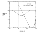
- FIG. 1 shows the frequency sensitivity distribution of Pacinian corpuscles and Meissner's corpuscles.
- 5A and 5B are diagrams illustrating an example of gain adjustment in a first gain adjustment section according to the first embodiment; 4 is a diagram illustrating an example of an output history of a microphone in the first embodiment.
- FIG. 4 is a diagram illustrating an example of a correlation between the sound pressure of background noise and the frequency in the first embodiment.
- 5A and 5B are diagrams illustrating an example of gain adjustment in a second gain adjustment unit in the first embodiment; 1 is a diagram showing a schematic layout of an interior of a vehicle in which an information transmission device according to a first embodiment is provided; 1 is a diagram showing a schematic configuration of an automatic driving system for a vehicle equipped with a second embodiment of an information transmission device to which the present invention is applied;
- the information transmission device is provided in, for example, a four-wheeled vehicle (one example being an automobile such as a passenger car) in which the two front wheels are steered (turned).
- a vehicle is equipped with an electric power steering device that applies a steering assist force by means of an electric motor to a steering device that steers the front wheels.
- FIG. 1 is a diagram showing a schematic configuration of an electric power steering device for a vehicle according to a first embodiment.
- the electric power steering device 1 is composed of a steering wheel 10, a steering shaft 20, an intermediate shaft 21, a pinion shaft 22, a rack shaft 30, a rack housing 40, a tie rod 50, a housing 60, a steering angle sensor 71, a torque sensor 72, an actuator unit 80, an electric power steering control unit (EPS control unit) 90, etc.
- EPS control unit electric power steering control unit
- the steering wheel 10 is, for example, a circular ring-shaped operating member that is turned by a driver to input a steering operation.
- the steering wheel 10 is disposed in the passenger compartment of the vehicle, facing the driver's seat. The occupant (driver) senses the steering feeling of the vehicle from the sensation (tactile sensation) transmitted from the steering wheel 10 to his/her fingers.
- the steering shaft 20 is a rotating shaft having one end attached to the steering wheel 10, and transmits the rotational motion of the steering wheel 10 to a rack and pinion mechanism that converts it into translational motion in the vehicle width direction.
- An intermediate shaft 21 and a pinion shaft 22 are connected in this order to the end of the steering shaft 20 opposite the steering wheel 10 side.
- Universal joints (Cardan joints) 23, 24 are provided between the steering shaft 20 and the intermediate shaft 21, and between the intermediate shaft 21 and the pinion shaft 22, respectively, so that rotation can be transmitted when the shafts are bent.
- a pinion gear is formed at the tip of the pinion shaft 22 , which meshes with a rack gear 31 of the rack shaft 30 to drive the rack shaft 30 .
- the rack shaft 30 is a columnar member arranged such that its longitudinal direction (axial direction) is aligned with the vehicle width direction.
- the rack shaft 30 is supported so as to be capable of translation in the vehicle width direction relative to the vehicle body.
- a rack gear 31 that meshes with the pinion gear of the pinion shaft 22 is formed on a part of the rack shaft 30 .
- the rack gear 31 of the rack shaft 30 is driven by the pinion gear, and moves in a translational (straight) direction along the vehicle width direction.
- the rack gear 31 is disposed offset to either the left or right side (usually the driver's seat side) in the vehicle width direction. For example, if the vehicle is a so-called right-hand drive vehicle with the driver's seat on the right front seat, the rack gear 31 is positioned offset to the right of the center when in neutral.
- the rack housing 40 is a substantially cylindrical member that supports and houses the rack shaft 30 so that the rack shaft 30 is relatively displaceable in the vehicle width direction.
- Rack boots 41 are provided on both ends of the rack housing 40 .
- the rack boot 41 is a member that prevents foreign matter such as dust from entering the rack housing 40 while allowing relative displacement of the tie rod 50 with respect to the rack housing 40 .
- the rack boot 41 is made of a resin material such as an elastomer and has a flexible bellows-like shape.
- the tie rod 50 is an axial interlocking member that connects the end of the rack shaft 30 and a knuckle arm 61 of the housing 60 and rotates the housing 60 about the kingpin axis in conjunction with the translational movement of the rack shaft 30.
- An inner end of the tie rod 50 in the vehicle width direction is swingably connected to an end of the rack shaft 30 via a ball joint 51 .
- the outer end of the tie rod 50 in the vehicle width direction is connected to a knuckle arm 61 of a housing 60 via a ball joint 52 .
- the housing (knuckle) 60 is a member that accommodates a hub bearing that supports the wheel W rotatably around the axle.
- the housing 60 has a knuckle arm 61 formed to protrude forward or rearward with respect to the axle.
- the housing 60 is supported so as to be rotatable about a kingpin axis, which is a predetermined central axis of rotation.
- the kingpin axis is an imaginary axis connecting the bearing center of the strut top mount and the center of the ball joint that connects the lower part of the housing 60 and the transverse link (lower arm).
- the housing 60 is pushed and pulled in the vehicle width direction by the rack shaft 30 via the tie rod 50, thereby rotating about the kingpin axis and steering the wheels W.
- the steering angle sensor 71 is an angle encoder that detects the rotational angle position of the pinion shaft 22 .
- the output of the steering angle sensor 71 is transmitted to an electric power steering control unit 90 .
- the electric power steering control unit 90 is capable of calculating the steering angle ⁇ of the wheels W (the toe change angle associated with steering) based on the output of the steering angle sensor 71 .
- the torque sensor 72 is a sensor that detects the torque acting on the pinion shaft 22 (mainly the steering force applied by the driver).
- the torque sensor 72 is provided on a portion of the pinion shaft 22 closer to the intermediate shaft 21 than the actuator unit 80 is.
- the output of the torque sensor 72 is transmitted to an electric power steering control unit 90 .
- the actuator unit 80 is a drive device that rotates the pinion shaft 22 to provide power assist during manual driving and perform steering operations during automatic driving.
- the actuator unit 80 includes a motor 81, a gear box 82, and the like.
- the motor 81 is an electric actuator that generates a driving force to be applied to the steering shaft 20 .
- the rotation direction and output torque of the motor 81 are controlled by an electric power steering control unit 90 .
- the gear box 82 is equipped with a reduction gear train that reduces the speed (torque amplifies) of the rotational output of the motor 81 and transmits it to the pinion shaft 22 .
- An electric power steering (EPS) control unit 90 is a control device (motor control unit) that gives a current command value to the motor 81 to control the rotation direction and output torque.
- the electric power steering control unit 90 can be configured as a microcomputer having, for example, an information processing section such as a CPU, a storage section such as a RAM or a ROM, an input/output interface, and a bus connecting these.
- the electric power steering control unit 90 is capable of acquiring information such as the outputs of the steering angle sensor 71 and the torque sensor 72, the vehicle's running speed (vehicle speed), and the operating status of other on-board electronic devices, either directly or via an on-board LAN such as a CAN communication system.
- the electric power steering control unit 90 sets a current command value to be given to the motor 81 based on the torque input direction and the detected torque value of the torque sensor 72 .
- the electric power steering control unit 90 includes a power supply device that supplies electric power of a current value and a voltage value according to a current command value to the motor 81 via a signal line.
- FIG. 2 is a diagram illustrating a system configuration of the information transmission device according to the first embodiment.
- the information transmission device 100 vibrates the air around the ears of the occupants using speakers 170 arranged in the vehicle cabin, and notifies the occupants of impending vehicle behavior by means of acoustic signals.
- the information transmission device 100 includes a waveform generating section 110, a differential calculation section 120, a first gain adjustment section 130, a microphone 140, a sensing value calculation section 150, a second gain adjustment section 160, a speaker 170, and the like.
- the waveform generating section 110 generates an excitation waveform, which is the waveform of an acoustic signal generated by the speaker 170 .
- FIG. 3 is a diagram illustrating an example of a vibration waveform in the first embodiment.
- the horizontal axis represents time
- the vertical axis represents voltage (amplitude).
- the excitation waveform can be a sine wave.
- the excitation waveform may be a waveform in which a plurality of sine waves with different wavelengths are superimposed (combined).
- the vibration waveforms are not limited to these and can be changed as appropriate.
- various waveforms such as a square wave, a triangular wave, and a waveform simulating the sound of a vehicle running can be used alone or in combination with other waveforms.
- the frequency of the vibration waveform can be set to have a dominant frequency in the range of, for example, 100 to 400 Hz, more preferably, 150 to 300 Hz.
- the sensory receptors that detect the vibrations include Merkel cells, Meissner's corpuscles, and Pacinian corpuscles.
- FIG. 4 is a diagram showing a schematic diagram of the timing of an electrical pulse emitted by a receptor when stimulated.
- the horizontal axis indicates time
- the vertical axis indicates, from the top, pressure and the electrical pulse generation state of Merkel cells, Meissner's corpuscles, and Pacinian corpuscles.
- Merkel cells have a relatively slow response and respond to a direct current component.
- Meissner's corpuscles correspond to when a rate of change (velocity) of contact pressure occurs.
- Pacinian corpuscles respond to moments of transient change and are said to be the most sensitive of these receptors. It is believed that the Pacinian corpuscles are the most sensitive receptors for allowing passengers to sense minute vibrations as combined auditory and tactile information.
- FIG. 5 is a diagram showing the frequency sensitivity distribution of Pacinian corpuscles and Meissner corpuscles.
- the horizontal axis indicates frequency and the vertical axis indicates amplitude above the threshold, with smaller values indicating better sensitivity.
- the Pacinian corpuscles exhibit good sensitivity in the region around 100 to 400 Hz, and even better sensitivity in the region around 150 to 300 Hz. Such a range is included in the range of 20 Hz to 20 kHz, which is generally considered to be the range of human hearing.
- the dominant frequency of the excitation waveform can be set to 250 Hz, for example.
- the differential calculation section 120 acquires information on the steering angle ⁇ of the wheels W detected by the steering angle sensor 71 from the electric power steering control unit 90, and calculates a differential value ⁇ by time differentiation.
- the differential calculation unit 120 sequentially transmits the calculated differential value ⁇ to the first gain adjustment unit 130 .
- the first gain adjustment section 130 performs a first gain adjustment, which will be described below, on the fundamental wave of the excitation waveform generated by the waveform generation section 110 .
- the first gain adjustment changes the gain G1, which is the output gain multiplied by the voltage of the excitation waveform, in accordance with the differential value (rate of change per time) of the steering angle ⁇ of the steering device (a parameter correlated to the steering amount).
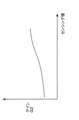
- FIG. 6 is a diagram illustrating an example of gain adjustment in the first gain adjustment unit.
- the horizontal axis indicates the absolute value of the differential value ⁇ of the steering angle ⁇ of the wheel FW
- the vertical axis indicates the gain G1 by which the voltage of the excitation waveform is multiplied.
- the gain G1 may be configured to increase in accordance with an increase in the absolute value of the differential value ⁇ .
- the rate of increase in gain G1 in response to an increase in the absolute value of the differential value ⁇ in the first gain adjustment unit 130 can be configured to be maximum in a region where the absolute value of the differential value ⁇ is small, and to decrease as the absolute value of the differential value ⁇ increases.
- the gain G1 in the first gain adjustment unit 130 can be calculated, for example, from the absolute value of the differential value ⁇ of the steering angle ⁇ using a logarithmic function.
- the gain G1 is expressed, for example, by the following equation 1.
- Gain G1 log(absolute value of steering angle differential value ⁇ coefficient k) (Equation 1)
- the coefficient k can be a value set, for example, during the development stage of the vehicle, in accordance with the characteristics of the vehicle (for example, the yaw gain relative to the steering angle ⁇ , the center of gravity position, etc.).
- the microphone 140 is provided inside the vehicle cabin and is a sound collecting device that collects background noise inside the vehicle cabin.
- the microphone 140 is preferably disposed in a position close to the ear of the passenger, and may be provided, for example, in the headrest portion of the seat.
- the output of the microphone 140 is transmitted to the sensing value calculation unit 150 .
- the sensing value calculation unit 150 extracts components of a predetermined frequency band from the background noise of the vehicle acquired by the microphone 140, and transmits the sound pressure of the extracted components to the second gain adjustment unit 160 as a sensing value.
- FIG. 7 is a diagram illustrating an example of an output history of a microphone. In FIG. 7, the horizontal axis indicates time, and the vertical axis indicates the sound pressure of the background noise picked up by the microphone 140.
- the sensing value calculation unit 150 performs a fast Fourier transform (FFT) process on the acoustic signal of the background noise acquired by the microphone 140 to convert it into the frequency domain, and further performs a band-pass filter process to extract components in a predetermined frequency band.
- the frequency band to be extracted is set so as to include the dominant frequency of the excitation waveform output by the waveform generating unit 110 .
- the sensing value calculation section 150 sets the average sound pressure of the extracted frequency band as a sensing value to be used in the second gain adjustment.
- FIG. 8 is a diagram showing an example of the correlation between the sound pressure of background noise and the frequency.
- the horizontal axis represents frequency
- the vertical axis represents sound pressure.
- the bandpass filter can be configured to extract a frequency band in the vicinity of the dominant frequency (for example, 250 Hz) of the excitation waveform in the waveform generating unit 110, for example.
- the sound pressure in the extracted frequency band (for example, the average value of the frequency band) is provided to the second gain adjuster 160 as a sensing value.
- the second gain adjustment section 160 further performs a second gain adjustment, which will be described below, on the vibration waveform after the first gain adjustment.
- the second gain adjustment changes the gain of the excitation waveform according to the sensing value of the noise inside the vehicle in order to adjust the output amplitude of the excitation waveform according to changes in background noise (drivetrain noise, aerodynamic noise, road noise, etc.) while the vehicle is running.
- the second gain adjustment unit 160 performs a second gain adjustment based on the output of the sensing value calculation unit 150 .
- the second gain adjustment section 160 sets the gain G2 based on the sensing value output by the sensing value calculation section 150 .
- FIG. 9 is a diagram illustrating an example of gain adjustment in the second gain adjustment section.
- the horizontal axis indicates the sensing value
- the vertical axis indicates the gain G2 by which the voltage of the vibration waveform is multiplied.
- the gain G2 can be configured to increase as the sensing value increases.
- the gain G2 is set so that the sound pressure of the sound generated by the excitation amplitude output from the speaker 170 does not dominate the sound pressure of background noise near the ears of the passengers.
- the gain G2 is set so that the sound generated by the excitation amplitude blends into the background noise of the vehicle and reaches a sound pressure level that can be unconsciously heard by the occupants.
- Equation 2 The output value (voltage) A of the vibration waveform after the first gain adjustment and the second gain adjustment described above is expressed by Equation 2.
- Output value A Waveform generating unit output value x Gain G1
- Gain G2 Waveform generating unit output value ⁇ log (absolute value of steering angle differential value ⁇ ⁇ coefficient k) ⁇ Gain G2 (Equation 2)
- the speaker 170 is a vibration device that is disposed inside the vehicle cabin and uses the output value A to vibrate the air around the passengers in the vehicle cabin to generate sound.
- Speaker 170 may be configured to be shared with a speaker used for audio reproduction in an in-car audio device, for example.
- a speaker 170 dedicated to the information transmission device 100 may be provided.
- FIG. 10 is a diagram showing a schematic layout of the interior of a vehicle in which the information transmission device of the first embodiment is provided. Inside the vehicle interior 200, a driver's seat 210, a passenger seat 220, a rear seat 230, an instrument panel 240, etc. are provided.
- a driver's seat 210 and a passenger seat 220 are front seats provided at the front of the vehicle compartment.
- a driver's seat 210 and a passenger seat 220 are provided side by side in the vehicle width direction.
- the vehicle is, as an example, a so-called right-hand drive vehicle, with the driver's seat 210 being provided on the right side and the passenger seat 220 being provided on the left side with respect to the center of the vehicle body in the lateral direction.
- the driver's seat 210 and the passenger seat 220 each have a cushion portion on which the occupant's buttocks and thighs are placed, a seat back portion disposed behind the occupant's back, and a headrest portion disposed behind the occupant's head.
- the rear seat 230 is a bench-like seat arranged behind the driver's seat 210 and the passenger seat 220.
- the rear seat 230 can accommodate, for example, two passengers sitting side by side.
- the rear seat 230 has a cushion portion on which the occupant's buttocks and thighs are placed, a seat back portion disposed behind the occupant's back, and a headrest portion provided behind the occupant's head.
- the right seating portion of the rear seat 230 is disposed behind the driver's seat 210
- the left seating portion is disposed behind the passenger seat 220 .
- the instrument panel 240 is provided near the front end of the vehicle interior 200, and is a member that houses, for example, an instrument panel, an air conditioning and heating system, an infotainment system, and the like.
- the instrument panel 240 is disposed so as to face the occupants seated in the driver's seat 210 and the passenger seat 220 .
- each speaker 170 is provided spaced apart on the front, rear, left and right sides of the vehicle interior 200.
- the reference numerals of the speakers 170 are given subscripts corresponding to their positions.
- the right front speaker 170FR is disposed near the right end of the instrument panel 240.
- the speaker 170FR is a directional speaker that is directed toward the head (ears) of an occupant seated in the driver's seat 210.
- the left front speaker 170FL is disposed near the left end of the instrument panel 240.
- Speaker 170FL is a directional speaker that is directed toward the head (ears) of an occupant seated in passenger seat 220.
- the right rear speaker 170RR is disposed in the headrest portion of the driver's seat 210.
- Speaker 170RR is a directional speaker that is directed toward the head (ear) of an occupant seated on the right side of rear seat 230.
- the left rear speaker 170RL is disposed in the headrest of the passenger seat 220.
- Speaker 170RL is a directional speaker that is directed toward the head (ear) of an occupant seated on the left side of rear seat 230.
- the sound can enable occupants to predict the occurrence of a behavior that will occur at the beginning of steering, before the lateral acceleration, yaw rate, roll angle, etc. actually occur in the vehicle. This improves the occupant's predictability of vehicle behavior, and prevents the occupant from feeling abruptness due to the vehicle behavior. This allows the occupant to prepare for the occurrence of acceleration or the like by, for example, exerting force on the body, thereby preventing the occupant from unintentionally losing his/her seated position, etc.
- the excitation waveform has a dominant frequency in the frequency band of 100 to 400 Hz, more preferably 150 to 300 Hz, so that Pacinian corpuscles, which are in the audible range and highly sensitive to skin sensation, can be used, improving the passenger's perception of sound through acoustics and recognition of skin sensation. This allows information to be transmitted to the passenger more reliably.
- (3) By setting the gain G1 using a logarithmic function from the absolute value of the derivative value ⁇ of the steering angle ⁇ , it is possible to set a large gain G1 even in an area where the absolute value of the derivative value ⁇ is relatively small.
- the vehicle is provided with an automatic driving function that performs steering operations, acceleration/deceleration operations, etc., independently of the driving operations of the driver.
- FIG. 11 is a diagram illustrating a schematic configuration of an automatic driving system for a vehicle in which an information transmission device according to the second embodiment is provided.
- the autonomous driving system 300 includes, in addition to the electric power steering control unit 90 described above, an autonomous driving control unit 310, an engine control unit 320, a transmission control unit 330, a brake control unit 340, and the like.
- Each of these units includes a microcomputer having an information processing section such as a CPU, a storage section such as a RAM or a ROM, an input/output interface, and a bus connecting these.
- each unit is connected directly or via an in-vehicle LAN such as a CAN communication system, and is capable of communicating with each other.
- the autonomous driving control unit 310 recognizes the environment around the vehicle using various sensors such as a stereo camera device, a millimeter wave radar device, a laser scanner device, and a high-precision 3D map.
- the autonomous driving control unit 310 generates an autonomous driving scenario based on the recognized environment, including information regarding the vehicle's driving line, speed, etc.
- the autonomous driving control unit 310 issues instructions to the electric power steering control unit 90, the engine control unit 320, the transmission control unit 330, and the brake control unit 340 based on an autonomous driving scenario, and controls the steering and acceleration/deceleration of the vehicle.
- the electric power steering control unit 90 controls the actuator unit 80 in response to the required steering angle instructed by the automatic driving control unit 310, and steers the wheels W.
- the engine control unit 320 comprehensively controls the engine, which is the power source for running the vehicle, and its accessories.
- the engine control unit 320 controls the output of the engine so that the torque actually generated by the engine matches the required torque specified by the automatic driving control unit 310 .
- the transmission control unit 330 comprehensively controls the transmission, which changes the speed (slows down or speeds up) the rotation of the output shaft of the engine, and its accessories.
- the transmission control unit 330 switches between the driving range and the non-driving range, switches between forward and reverse travel, and changes gears (changes the gear ratio) when traveling forward, in response to instructions from the automatic driving control unit 310.
- the brake control unit 340 controls the braking force of the hydraulic service brakes provided on each wheel of the vehicle.
- the brake control unit 340 adjusts the brake fluid pressure supplied to the wheel cylinders of each wheel in accordance with the required braking force instructed by the automatic driving control unit 310, and generates the necessary braking force.
- the required steering angle transmitted from the autonomous driving control unit 310 to the electric power steering control unit 90 is used as an input to the information transmission device 100 (a parameter correlated with the steering angle of the steering device), and a first gain adjustment is performed based on its differential value.
- the information transmission device 100 a parameter correlated with the steering angle of the steering device
- a first gain adjustment is performed based on its differential value.
- the present invention is not limited to the above-described embodiment, and various modifications and variations are possible, which are also within the technical scope of the present invention.
- the configurations of the information transmission device and the vehicle are not limited to those in the above-described embodiments and may be modified as appropriate.
- the hardware configuration of the information transmission device and the specific method of adjusting the gain of the vibration waveform are not limited to the configurations of each embodiment and can be changed as appropriate.
- a steering angle actual steering angle detected by a steering angle sensor, or a required steering angle in automatic driving control
- the parameter is not limited to this and can be changed as appropriate.
- the configuration may include at least one of the steering torque (input torque) input from the driver, the amount of operation of an actuator that steers the wheels (for example, the amount of rotation of a motor), and an output instruction value to the actuator.
- the present invention is not limited to those in which an operating member such as a steering wheel is mechanically connected to a steering mechanism such as a steering gear box as in the respective embodiments, but can also be applied to a vehicle having a steer-by-wire type steering device in which the steering mechanism is not mechanically connected to the steering wheel, etc.
- the actual steering angle of the front wheels and the state of the steering mechanism (for example, the rotation angle position of the pinion gear, the amount of movement of the rack shaft, etc.) can be used as parameters correlated with the steering amount of the steering device.
- the level of background noise of the vehicle is obtained by a microphone as an example, but the invention is not limited to this and the level of background noise may be obtained by other methods.
- the level of background noise may be estimated based on the acceleration of the unsprung part of the vehicle, which correlates with the input from the road surface, or the output value of a torque sensor of the steering device (torsion bar torque).
Landscapes
- Engineering & Computer Science (AREA)
- Transportation (AREA)
- Mechanical Engineering (AREA)
- Automation & Control Theory (AREA)
- Chemical & Material Sciences (AREA)
- Combustion & Propulsion (AREA)
- Human Computer Interaction (AREA)
- Steering Control In Accordance With Driving Conditions (AREA)
- Fittings On The Vehicle Exterior For Carrying Loads, And Devices For Holding Or Mounting Articles (AREA)
Priority Applications (3)
| Application Number | Priority Date | Filing Date | Title |
|---|---|---|---|
| DE112023004987.4T DE112023004987T5 (de) | 2022-11-28 | 2023-07-31 | Informationsübermittlungs-einrichtung |
| CN202380072116.3A CN120018988A (zh) | 2022-11-28 | 2023-07-31 | 信息传递装置 |
| JP2024561156A JP7737571B2 (ja) | 2022-11-28 | 2023-07-31 | 情報伝達装置 |
Applications Claiming Priority (2)
| Application Number | Priority Date | Filing Date | Title |
|---|---|---|---|
| JP2022188852 | 2022-11-28 | ||
| JP2022-188852 | 2022-11-28 |
Publications (1)
| Publication Number | Publication Date |
|---|---|
| WO2024116465A1 true WO2024116465A1 (ja) | 2024-06-06 |
Family
ID=91323253
Family Applications (1)
| Application Number | Title | Priority Date | Filing Date |
|---|---|---|---|
| PCT/JP2023/027929 Ceased WO2024116465A1 (ja) | 2022-11-28 | 2023-07-31 | 情報伝達装置 |
Country Status (4)
| Country | Link |
|---|---|
| JP (1) | JP7737571B2 (https=) |
| CN (1) | CN120018988A (https=) |
| DE (1) | DE112023004987T5 (https=) |
| WO (1) | WO2024116465A1 (https=) |
Cited By (4)
| Publication number | Priority date | Publication date | Assignee | Title |
|---|---|---|---|---|
| WO2026009359A1 (ja) * | 2024-07-03 | 2026-01-08 | 株式会社Subaru | 車両 |
| WO2026022917A1 (ja) * | 2024-07-22 | 2026-01-29 | 株式会社Subaru | 装着型端末 |
| WO2026028359A1 (ja) * | 2024-07-31 | 2026-02-05 | 株式会社Subaru | 車両 |
| WO2026028360A1 (ja) * | 2024-07-31 | 2026-02-05 | 株式会社Subaru | 車両 |
Citations (12)
| Publication number | Priority date | Publication date | Assignee | Title |
|---|---|---|---|---|
| JPH07215144A (ja) * | 1994-02-04 | 1995-08-15 | Mitsubishi Motors Corp | 操舵系加振式車両用警告装置 |
| JP2006298166A (ja) * | 2005-04-20 | 2006-11-02 | Honda Motor Co Ltd | 車両状態伝達装置 |
| JP2007062706A (ja) * | 2005-08-05 | 2007-03-15 | Nissan Motor Co Ltd | 運転支援装置および運転支援方法 |
| JP2008162466A (ja) * | 2006-12-28 | 2008-07-17 | Toyoda Gosei Co Ltd | ステアリングホイール |
| JP2008265613A (ja) * | 2007-04-23 | 2008-11-06 | Jtekt Corp | 電動パワーステアリング装置 |
| JP2010083245A (ja) * | 2008-09-30 | 2010-04-15 | Denso Corp | 計器用警報装置 |
| JP2012006534A (ja) * | 2010-06-28 | 2012-01-12 | Nissan Motor Co Ltd | 車両の走行支援装置及び走行支援方法 |
| JP2017144779A (ja) * | 2016-02-15 | 2017-08-24 | 株式会社ジェイテクト | 車両用警報装置 |
| WO2018230443A1 (ja) * | 2017-06-12 | 2018-12-20 | 株式会社バンダイナムコエンターテインメント | シミュレーションシステム、画像処理方法及び情報記憶媒体 |
| JP2019202591A (ja) * | 2018-05-22 | 2019-11-28 | マツダ株式会社 | ステアリング装置 |
| WO2020235306A1 (ja) * | 2019-05-17 | 2020-11-26 | 株式会社東海理化電機製作所 | 制御システムおよび提示システム |
| WO2022018926A1 (ja) * | 2020-07-22 | 2022-01-27 | 日本電産サンキョー株式会社 | 入力装置および入力装置の制御方法 |
-
2023
- 2023-07-31 DE DE112023004987.4T patent/DE112023004987T5/de active Pending
- 2023-07-31 JP JP2024561156A patent/JP7737571B2/ja active Active
- 2023-07-31 CN CN202380072116.3A patent/CN120018988A/zh active Pending
- 2023-07-31 WO PCT/JP2023/027929 patent/WO2024116465A1/ja not_active Ceased
Patent Citations (12)
| Publication number | Priority date | Publication date | Assignee | Title |
|---|---|---|---|---|
| JPH07215144A (ja) * | 1994-02-04 | 1995-08-15 | Mitsubishi Motors Corp | 操舵系加振式車両用警告装置 |
| JP2006298166A (ja) * | 2005-04-20 | 2006-11-02 | Honda Motor Co Ltd | 車両状態伝達装置 |
| JP2007062706A (ja) * | 2005-08-05 | 2007-03-15 | Nissan Motor Co Ltd | 運転支援装置および運転支援方法 |
| JP2008162466A (ja) * | 2006-12-28 | 2008-07-17 | Toyoda Gosei Co Ltd | ステアリングホイール |
| JP2008265613A (ja) * | 2007-04-23 | 2008-11-06 | Jtekt Corp | 電動パワーステアリング装置 |
| JP2010083245A (ja) * | 2008-09-30 | 2010-04-15 | Denso Corp | 計器用警報装置 |
| JP2012006534A (ja) * | 2010-06-28 | 2012-01-12 | Nissan Motor Co Ltd | 車両の走行支援装置及び走行支援方法 |
| JP2017144779A (ja) * | 2016-02-15 | 2017-08-24 | 株式会社ジェイテクト | 車両用警報装置 |
| WO2018230443A1 (ja) * | 2017-06-12 | 2018-12-20 | 株式会社バンダイナムコエンターテインメント | シミュレーションシステム、画像処理方法及び情報記憶媒体 |
| JP2019202591A (ja) * | 2018-05-22 | 2019-11-28 | マツダ株式会社 | ステアリング装置 |
| WO2020235306A1 (ja) * | 2019-05-17 | 2020-11-26 | 株式会社東海理化電機製作所 | 制御システムおよび提示システム |
| WO2022018926A1 (ja) * | 2020-07-22 | 2022-01-27 | 日本電産サンキョー株式会社 | 入力装置および入力装置の制御方法 |
Cited By (4)
| Publication number | Priority date | Publication date | Assignee | Title |
|---|---|---|---|---|
| WO2026009359A1 (ja) * | 2024-07-03 | 2026-01-08 | 株式会社Subaru | 車両 |
| WO2026022917A1 (ja) * | 2024-07-22 | 2026-01-29 | 株式会社Subaru | 装着型端末 |
| WO2026028359A1 (ja) * | 2024-07-31 | 2026-02-05 | 株式会社Subaru | 車両 |
| WO2026028360A1 (ja) * | 2024-07-31 | 2026-02-05 | 株式会社Subaru | 車両 |
Also Published As
| Publication number | Publication date |
|---|---|
| JPWO2024116465A1 (https=) | 2024-06-06 |
| DE112023004987T5 (de) | 2025-10-23 |
| CN120018988A (zh) | 2025-05-16 |
| JP7737571B2 (ja) | 2025-09-10 |
Similar Documents
| Publication | Publication Date | Title |
|---|---|---|
| JP7737571B2 (ja) | 情報伝達装置 | |
| JP4166684B2 (ja) | 車両安定性向上システムのための方法及び装置 | |
| JP7319832B2 (ja) | ステアリング装置 | |
| JP2006264624A (ja) | 車線維持支援装置 | |
| WO2024116466A1 (ja) | 情報伝達装置 | |
| US20230242177A1 (en) | Electric power steering system | |
| CN102958784B (zh) | 用于机电式调节转向角的方法以及具有机电式转向装置的机动车 | |
| WO2024154252A1 (ja) | 情報伝達装置 | |
| US12122232B2 (en) | Accelerator pedal apparatus | |
| JP2023133202A (ja) | 道路車両の運転支援方法 | |
| JP2019172156A (ja) | 車両用制御装置 | |
| WO2025062622A1 (ja) | 情報提示装置 | |
| WO2025079133A1 (ja) | 情報伝達装置 | |
| WO2024218847A1 (ja) | 情報提示装置 | |
| JP7821026B2 (ja) | 車両用シート | |
| WO2022113426A1 (ja) | サスペンション制御装置、車両およびサスペンション制御方法 | |
| WO2024195027A1 (ja) | 情報提示装置 | |
| WO2025115207A1 (ja) | 情報提示装置 | |
| JP5004798B2 (ja) | 自動車の制御方法、自動車の制御装置及び自動車 | |
| JP7853819B2 (ja) | ブレーキペダル装置 | |
| CN114585555A (zh) | 操作汽车的空气导向装置的方法和汽车的空气导向装置 | |
| WO2026028360A1 (ja) | 車両 | |
| WO2026028359A1 (ja) | 車両 | |
| JP2024111619A (ja) | ドライビングシミュレータ | |
| WO2024195028A1 (ja) | 情報提示装置 |
Legal Events
| Date | Code | Title | Description |
|---|---|---|---|
| 121 | Ep: the epo has been informed by wipo that ep was designated in this application |
Ref document number: 23897125 Country of ref document: EP Kind code of ref document: A1 |
|
| WWE | Wipo information: entry into national phase |
Ref document number: 2024561156 Country of ref document: JP |
|
| WWE | Wipo information: entry into national phase |
Ref document number: 202380072116.3 Country of ref document: CN |
|
| WWP | Wipo information: published in national office |
Ref document number: 202380072116.3 Country of ref document: CN |
|
| WWE | Wipo information: entry into national phase |
Ref document number: 112023004987 Country of ref document: DE |
|
| WWP | Wipo information: published in national office |
Ref document number: 112023004987 Country of ref document: DE |
|
| 122 | Ep: pct application non-entry in european phase |
Ref document number: 23897125 Country of ref document: EP Kind code of ref document: A1 |