WO2024116393A1 - 電極端子及び電池 - Google Patents
電極端子及び電池 Download PDFInfo
- Publication number
- WO2024116393A1 WO2024116393A1 PCT/JP2022/044479 JP2022044479W WO2024116393A1 WO 2024116393 A1 WO2024116393 A1 WO 2024116393A1 JP 2022044479 W JP2022044479 W JP 2022044479W WO 2024116393 A1 WO2024116393 A1 WO 2024116393A1
- Authority
- WO
- WIPO (PCT)
- Prior art keywords
- electrode terminal
- negative electrode
- joined
- battery
- metal
- Prior art date
- Legal status (The legal status is an assumption and is not a legal conclusion. Google has not performed a legal analysis and makes no representation as to the accuracy of the status listed.)
- Ceased
Links
Images






Classifications
-
- H—ELECTRICITY
- H01—ELECTRIC ELEMENTS
- H01M—PROCESSES OR MEANS, e.g. BATTERIES, FOR THE DIRECT CONVERSION OF CHEMICAL ENERGY INTO ELECTRICAL ENERGY
- H01M50/00—Constructional details or processes of manufacture of the non-active parts of electrochemical cells other than fuel cells, e.g. hybrid cells
- H01M50/50—Current conducting connections for cells or batteries
- H01M50/543—Terminals
- H01M50/564—Terminals characterised by their manufacturing process
- H01M50/566—Terminals characterised by their manufacturing process by welding, soldering or brazing
-
- H—ELECTRICITY
- H01—ELECTRIC ELEMENTS
- H01M—PROCESSES OR MEANS, e.g. BATTERIES, FOR THE DIRECT CONVERSION OF CHEMICAL ENERGY INTO ELECTRICAL ENERGY
- H01M50/00—Constructional details or processes of manufacture of the non-active parts of electrochemical cells other than fuel cells, e.g. hybrid cells
- H01M50/10—Primary casings; Jackets or wrappings
- H01M50/172—Arrangements of electric connectors penetrating the casing
- H01M50/174—Arrangements of electric connectors penetrating the casing adapted for the shape of the cells
- H01M50/176—Arrangements of electric connectors penetrating the casing adapted for the shape of the cells for prismatic or rectangular cells
-
- H—ELECTRICITY
- H01—ELECTRIC ELEMENTS
- H01M—PROCESSES OR MEANS, e.g. BATTERIES, FOR THE DIRECT CONVERSION OF CHEMICAL ENERGY INTO ELECTRICAL ENERGY
- H01M50/00—Constructional details or processes of manufacture of the non-active parts of electrochemical cells other than fuel cells, e.g. hybrid cells
- H01M50/50—Current conducting connections for cells or batteries
- H01M50/502—Interconnectors for connecting terminals of adjacent batteries; Interconnectors for connecting cells outside a battery casing
- H01M50/503—Interconnectors for connecting terminals of adjacent batteries; Interconnectors for connecting cells outside a battery casing characterised by the shape of the interconnectors
-
- H—ELECTRICITY
- H01—ELECTRIC ELEMENTS
- H01M—PROCESSES OR MEANS, e.g. BATTERIES, FOR THE DIRECT CONVERSION OF CHEMICAL ENERGY INTO ELECTRICAL ENERGY
- H01M50/00—Constructional details or processes of manufacture of the non-active parts of electrochemical cells other than fuel cells, e.g. hybrid cells
- H01M50/50—Current conducting connections for cells or batteries
- H01M50/502—Interconnectors for connecting terminals of adjacent batteries; Interconnectors for connecting cells outside a battery casing
- H01M50/514—Methods for interconnecting adjacent batteries or cells
- H01M50/516—Methods for interconnecting adjacent batteries or cells by welding, soldering or brazing
-
- H—ELECTRICITY
- H01—ELECTRIC ELEMENTS
- H01M—PROCESSES OR MEANS, e.g. BATTERIES, FOR THE DIRECT CONVERSION OF CHEMICAL ENERGY INTO ELECTRICAL ENERGY
- H01M50/00—Constructional details or processes of manufacture of the non-active parts of electrochemical cells other than fuel cells, e.g. hybrid cells
- H01M50/50—Current conducting connections for cells or batteries
- H01M50/502—Interconnectors for connecting terminals of adjacent batteries; Interconnectors for connecting cells outside a battery casing
- H01M50/521—Interconnectors for connecting terminals of adjacent batteries; Interconnectors for connecting cells outside a battery casing characterised by the material
- H01M50/522—Inorganic material
-
- H—ELECTRICITY
- H01—ELECTRIC ELEMENTS
- H01M—PROCESSES OR MEANS, e.g. BATTERIES, FOR THE DIRECT CONVERSION OF CHEMICAL ENERGY INTO ELECTRICAL ENERGY
- H01M50/00—Constructional details or processes of manufacture of the non-active parts of electrochemical cells other than fuel cells, e.g. hybrid cells
- H01M50/50—Current conducting connections for cells or batteries
- H01M50/543—Terminals
- H01M50/547—Terminals characterised by the disposition of the terminals on the cells
- H01M50/548—Terminals characterised by the disposition of the terminals on the cells on opposite sides of the cell
-
- H—ELECTRICITY
- H01—ELECTRIC ELEMENTS
- H01M—PROCESSES OR MEANS, e.g. BATTERIES, FOR THE DIRECT CONVERSION OF CHEMICAL ENERGY INTO ELECTRICAL ENERGY
- H01M50/00—Constructional details or processes of manufacture of the non-active parts of electrochemical cells other than fuel cells, e.g. hybrid cells
- H01M50/50—Current conducting connections for cells or batteries
- H01M50/543—Terminals
- H01M50/547—Terminals characterised by the disposition of the terminals on the cells
- H01M50/55—Terminals characterised by the disposition of the terminals on the cells on the same side of the cell
-
- H—ELECTRICITY
- H01—ELECTRIC ELEMENTS
- H01M—PROCESSES OR MEANS, e.g. BATTERIES, FOR THE DIRECT CONVERSION OF CHEMICAL ENERGY INTO ELECTRICAL ENERGY
- H01M50/00—Constructional details or processes of manufacture of the non-active parts of electrochemical cells other than fuel cells, e.g. hybrid cells
- H01M50/50—Current conducting connections for cells or batteries
- H01M50/543—Terminals
- H01M50/552—Terminals characterised by their shape
- H01M50/553—Terminals adapted for prismatic, pouch or rectangular cells
-
- H—ELECTRICITY
- H01—ELECTRIC ELEMENTS
- H01M—PROCESSES OR MEANS, e.g. BATTERIES, FOR THE DIRECT CONVERSION OF CHEMICAL ENERGY INTO ELECTRICAL ENERGY
- H01M50/00—Constructional details or processes of manufacture of the non-active parts of electrochemical cells other than fuel cells, e.g. hybrid cells
- H01M50/50—Current conducting connections for cells or batteries
- H01M50/543—Terminals
- H01M50/552—Terminals characterised by their shape
- H01M50/553—Terminals adapted for prismatic, pouch or rectangular cells
- H01M50/557—Plate-shaped terminals
-
- H—ELECTRICITY
- H01—ELECTRIC ELEMENTS
- H01M—PROCESSES OR MEANS, e.g. BATTERIES, FOR THE DIRECT CONVERSION OF CHEMICAL ENERGY INTO ELECTRICAL ENERGY
- H01M50/00—Constructional details or processes of manufacture of the non-active parts of electrochemical cells other than fuel cells, e.g. hybrid cells
- H01M50/50—Current conducting connections for cells or batteries
- H01M50/543—Terminals
- H01M50/562—Terminals characterised by the material
-
- Y—GENERAL TAGGING OF NEW TECHNOLOGICAL DEVELOPMENTS; GENERAL TAGGING OF CROSS-SECTIONAL TECHNOLOGIES SPANNING OVER SEVERAL SECTIONS OF THE IPC; TECHNICAL SUBJECTS COVERED BY FORMER USPC CROSS-REFERENCE ART COLLECTIONS [XRACs] AND DIGESTS
- Y02—TECHNOLOGIES OR APPLICATIONS FOR MITIGATION OR ADAPTATION AGAINST CLIMATE CHANGE
- Y02E—REDUCTION OF GREENHOUSE GAS [GHG] EMISSIONS, RELATED TO ENERGY GENERATION, TRANSMISSION OR DISTRIBUTION
- Y02E60/00—Enabling technologies; Technologies with a potential or indirect contribution to GHG emissions mitigation
- Y02E60/10—Energy storage using batteries
Definitions
- the present invention relates to an electrode terminal and a battery.
- Patent Document 1 Technology for converting the material of battery electrode terminals has been known for some time (see, for example, Patent Document 1).
- the electrode terminal has a first member, a second member, and a third member.
- the first member is electrically connected to the charging/discharging body of the battery and contains a first metal.
- the second member has a first insertion portion into which the first member is inserted, is joined to the first member, and contains the first metal.
- the third member has a second insertion portion into which the first member is inserted, is joined to the second member, and contains a second metal of a material different from the first metal.
- the third member is joined to the conductive member on the opposing surface to the conductive member that electrically connects one battery to another battery and contains the second metal.
- the first member and the third member are adjacent to each other on the opposing surface side.
- the battery has the above-mentioned electrode terminals and a charge/discharge body electrically connected to the electrode terminals.
- the electrode terminal has a first member, a second member, and a third member.
- the first member is electrically connected to the charging/discharging body of the battery and contains a first metal.
- the second member is joined to the first member and contains the first metal.
- the third member is joined to the second member and contains a second metal of a different material than the first metal.
- the third member is not crimped to the first member.
- the third member is joined to the conductive member on the opposing surface to the conductive member that electrically connects one battery to another battery and contains the second metal.
- the first member, second member, and third member are adjacent to each other on the opposing surface side.
- the electrode terminal has a first member, a second member, and a third member.
- the first member is electrically connected to the charging/discharging body of the battery and contains a first metal.
- the second member is joined to the first member and contains the first metal.
- the third member is joined to the second member and contains a second metal that is different from the first metal.
- the third member is joined to the conductive member on a surface facing the conductive member that electrically connects one battery to another battery and contains the second metal.
- the first member does not protrude toward the conductive member side beyond the third member on the side of the facing surface.
- the third member and the conductive member are joined across the first member.
- the characteristics of the electrode terminals of batteries that have been converted can be improved.
- FIG. 1 is a perspective view showing a battery 1 according to a first embodiment.
- FIG. 4 is a perspective view showing a cross section of components around a negative electrode terminal 420 of the battery 1 .
- FIG. 3 is a side view showing the components of FIG. 2 .
- FIG. 4 is a perspective view showing a cross section of components around a positive electrode terminal 410 of the battery 1.
- FIG. 5 is a side view showing the components of FIG. 4 .
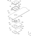
- FIG. 2 is a partially exploded perspective view of the battery 1.
- FIG. 2 is a perspective view showing a charging/discharging unit 100 of the battery 1.
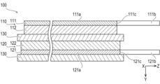
- 8 is a side view showing a cross section of a portion of the charge/discharge body 100 of FIG. 7 .
- FIG. 11 is a side view showing a cross section of a portion of a charge/discharge body 1100 according to a modified example.
- FIG. 4 is an exploded perspective view showing the components around the negative electrode terminal 420 of the battery 1.
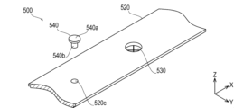
- FIG. 4 is an exploded perspective view showing peripheral components of a split valve 530 and a sealing plug 540 of the battery 1.
- FIG. 4 is an exploded perspective view showing the components around the positive terminal 410 of the battery 1.
- FIG. 4 is a cross-sectional perspective view of a negative electrode terminal 420 according to the first embodiment.
- FIG. 14 is an exploded perspective view of the negative electrode terminal 420 of FIG. 13 .
- FIG. 4 is a perspective view showing the connection between multiple batteries 1 and a bus bar 10.
- FIG. 4 is an end view showing a negative electrode terminal 420 and a bus bar 10 according to the first embodiment.
- FIG. 11 is an end view showing a negative electrode terminal 430 and a bus bar 10 according to a second embodiment.
- FIG. 11 is an end view showing a negative electrode terminal 440 and a bus bar 10 according to a third embodiment.
- FIG. 13 is an end view showing a negative electrode terminal 450 and a bus bar 10 according to the fourth embodiment.
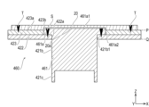
- FIG. 13 is an end view showing a negative electrode terminal 460 and a bus bar 20 according to a fifth embodiment.
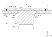
- FIG. 13 is an end view showing a negative electrode terminal 470 and a bus bar 10 according to a sixth embodiment.
- FIG. 13 is an end view showing a negative electrode terminal 480 and a bus bar 10 according to the seventh embodiment.
- FIG. 13 is a cross-sectional perspective view of a negative electrode terminal 490A according to an eighth embodiment.
- FIG. 24 is an exploded perspective view of the negative electrode terminal 490A of FIG. 23.
- FIG. 23 is a cross-sectional perspective view of a negative electrode terminal 490B according to a modified example of the eighth embodiment.
- the longitudinal direction X, lateral direction Y, and height direction Z of the battery 1 will change.
- FIG. 1 is a perspective view showing a battery 1 of the first embodiment.
- FIG. 2 is a perspective view showing in cross section the components around the negative terminal 420 of the battery 1.
- FIG. 3 is a side view showing the components of FIG. 2.
- FIG. 4 is a perspective view showing in cross section the components around the positive terminal 410 of the battery 1.
- FIG. 5 is a side view showing the components of FIG. 4.
- FIG. 6 is a perspective view showing a partially exploded battery 1.
- FIG. 7 is a perspective view showing a charging/discharging body 100 of the battery 1.
- FIG. 1 is a perspective view showing a battery 1 of the first embodiment.
- FIG. 2 is a perspective view showing in cross section the components around the negative terminal 420 of the battery 1.
- FIG. 3 is a side view showing the components of FIG. 2.
- FIG. 4 is a perspective view showing in cross section the components around the positive terminal 410 of the battery 1.
- FIG. 5 is a side view showing the components of FIG. 4.
- FIG. 8 is a side view showing in cross section a part of the charging/discharging body 100 of FIG. 7.
- FIG. 9 is a side view showing in cross section a part of a charging/discharging body 1100 of a modified example.
- FIG. 10 is a perspective view showing an exploded view of the components around the negative terminal 420 of the battery 1.
- FIG. 11 is a perspective view showing an exploded view of the components around the cleavage valve 530 and the sealing plug 540 of the battery 1.
- FIG. 12 is a perspective view showing an exploded view of the components around the positive terminal 410 of the battery 1.
- Battery 1 includes a charging/discharging body 100 that charges and discharges electricity, a current collector 200 connected to charging/discharging body 100, a current interrupter 300 connected to current collector 200, an electrode terminal 400 connected to current collector 200 or current interrupter 300, an exterior body 500 in which components of battery 1 are housed or attached, an insulator 600 that insulates the components of battery 1 from the exterior body 500, and a sealing body 700 that seals the components of battery 1 from the exterior body 500.
- the charge/discharge unit 100 charges and discharges electricity.
- the charge/discharge unit 100 shown in Figures 2 to 8 includes a positive electrode 110, a negative electrode 120, a separator 130, and an electrolyte 140.
- the charge/discharge unit 100 is constructed by winding components, in the order of the positive electrode 110, the separator 130, the negative electrode 120, and the separator 130, into a rectangular shape.
- the positive electrode 110 includes a long positive electrode current collecting layer 111 and a positive electrode active material layer 112 joined to the positive electrode current collecting layer 111.
- the positive electrode current collecting layer 111 includes a current collecting portion 111a and a positive electrode tab 111b.
- the positive electrode active material layer 112 is joined to the current collecting portion 111a. As shown in FIG. 8, the positive electrode active material layer 112 faces, for example, the entire area along the short side direction of the current collecting portion 111a.
- the positive electrode tab 111b protrudes in the short side direction of the current collecting portion 111a from a side edge 111c along the longitudinal direction of the current collecting portion 111a.
- the positive electrode tab 111b is formed integrally with the current collecting portion 111a.
- a plurality of positive electrode tabs 111b are formed on one current collecting portion 111a.
- the current collecting portion 111a is formed of, for example, aluminum or an aluminum alloy.
- the positive electrode active material layer 112 contains a positive electrode active material composed of a lithium-containing composite oxide, a binder, a conductive additive, and the like.
- the lithium-containing composite oxide contains, for example, metallic elements such as nickel (Ni), cobalt (Co), and manganese (Mn), and lithium (Li).
- the negative electrode 120 includes a long negative electrode current collecting layer 121 and a negative electrode active material layer 122 bonded to the negative electrode current collecting layer 121.
- the negative electrode current collecting layer 121 includes a current collecting portion 121a and a negative electrode tab 121b. As shown in FIG. 8, the current collecting portion 121a of the negative electrode 120 has a width along the short side direction that is longer than that of the current collecting portion 111a of the positive electrode 110. Both ends along the short side direction of the current collecting portion 111a of the positive electrode 110 are located within the range along the short side direction of the current collecting portion 121a of the negative electrode 120, via the separator 130.
- the negative electrode active material layer 122 is bonded to the current collecting portion 121a.
- the negative electrode active material layer 122 faces, for example, the entire area along the short side direction of the current collecting portion 121a.
- the negative electrode tab 121b protrudes in the short direction of the current collecting part 121a from a side edge 121c along the longitudinal direction of the current collecting part 121a.
- the negative electrode tab 121b protrudes in the same direction as the positive electrode tab 111b of the positive electrode 110.
- the negative electrode tab 121b is stacked with the positive electrode 110 via the separator 130, the negative electrode tab 121b is separated from the positive electrode tab 111b of the positive electrode 110.
- the negative electrode tab 121b is formed integrally with the current collecting part 121a.
- a plurality of negative electrode tabs 121b are formed on one current collecting part 121a.
- the current collecting part 121a is formed of, for example, copper or a copper alloy.
- the negative electrode active material layer 122 contains a negative electrode active material, a binder, a conductive assistant, and the like, which are made of a carbon-based material. For example, graphite is used as the carbon-based material.
- the separator 130 allows lithium ions to pass through while insulating the positive electrode 110 and the negative electrode 120.
- the separator 130 is formed in an elongated shape. As shown in FIG. 8, the separator 130 has a width along the short side longer than the current collector 111a of the positive electrode 110 and the current collector 121a of the negative electrode 120. Within the range along the short side of the separator 130, both ends along the short side of the current collector 111a of the positive electrode 110 are located, and both ends along the short side of the current collector 121a of the negative electrode 120 are located.
- the separator 130 is made of a porous material.
- the separator 130 is made of polyethylene (PE) or polypropylene (PP). A heat-resistant insulating material may be used instead of the separator 130. In such a configuration, the separator 130 is not essential.
- the electrolyte 140 contains an organic solvent, a supporting salt, and an additive.
- the electrolyte 140 is also called an electrolytic solution.
- a carbonate ester is used as the organic solvent.
- a lithium salt is used as the supporting salt.
- a charging/discharging body 1100 which is a modified example of the charging/discharging body 100, will be described with reference to FIG. 9.
- the configuration of the positive electrode 1110 of the charging/discharging body 1100 is different from that of the positive electrode 110 of the charging/discharging body 100.
- the positive electrode active material layer 1112 of the charging/discharging body 1100 faces the part of the current collecting part 111a except for both ends along the short side direction.
- the heat-resistant insulating layer 1113 of the charging/discharging body 1100 is joined to both ends along the short side direction of the current collecting part 111a and the base end portion of the positive electrode tab 111b.
- the current collector 200 is connected to the charge/discharge body 100.
- the current collector 200 is also called a current collector plate.
- the current collector 200 shown in Figures 2 to 5, 10, and 12 includes a positive current collector plate 210 and a negative current collector plate 220.
- the positive electrode current collector 210 conducts electricity between the positive electrode tab 111b of the charge/discharge unit 100 and the positive electrode terminal 410 via the current interrupter 300.
- the positive electrode current collector 210 includes a first base 210a in the shape of a rectangular parallelepiped plate, a second base 210b in the shape of a rectangular parallelepiped plate, and a connecting portion 210c that connects the first base 210a and the second base 210b in a stepped manner with different heights.
- a recess 210d is formed on the upper surface of the second base 210b by thinning the thickness of the second base 210b.
- a weak portion 210e is formed in the center of the recess 210d, which is recessed in a ring shape and partially weakens the recess 210d.
- the positive electrode current collector 210 is formed of, for example, aluminum or an aluminum alloy.
- the negative electrode collector plate 220 provides electrical continuity between the negative electrode tab 121b of the charge/discharge unit 100 and the negative electrode terminal 420.
- the negative electrode collector plate 220 includes a rectangular plate-shaped base 220a and an insertion hole 220b penetrating the base 220a.
- the insertion portion 420b of the negative electrode terminal 420 is inserted into the insertion hole 220b of the negative electrode collector plate 220.
- the negative electrode collector plate 220 is formed, for example, from copper or a copper alloy.
- the current interrupter 300 When the internal pressure of the battery 1 rises above a predetermined value, the current interrupter 300 separates from the positive collector plate 210, thereby opening the current path between the collector 200 and the positive terminal 410. When the internal pressure of the battery 1 is within a predetermined value, the current interrupter 300 maintains a state in which it is joined to the positive collector plate 210, thereby maintaining the current path between the collector 200 and the positive terminal 410.
- the current interrupter 300 is also called a current interrupting device (CID).
- the current interrupter 300 shown in Figures 4, 5, and 12 includes a diaphragm 310, a conductive member 320, and a pair of supports 330.
- the diaphragm 310 includes a curved cylindrical body 310a, a disk-shaped first joint 310b provided at the tip end of the body 310a, and a ring-shaped second joint 310c provided at the base end of the body 310a.
- the first joint 310b is joined to the recess 210d of the positive current collector 210.
- the second joint 310c is joined to the conductive member 320.
- the diaphragm 310 separates from the positive current collector 210 when the internal pressure of the battery 1 rises above a predetermined value.
- the diaphragm 310 is formed, for example, from aluminum or an aluminum alloy.
- the conductive member 320 is formed in a cylindrical shape.
- the conductive member 320 includes a disk-shaped base 320a and an insertion hole 320b that opens in the center of the base 320a.
- the positive electrode side first insulating plate 620 is joined to the upper surface of the conductive member 320.
- the second joint portion 310c of the diaphragm 310 is joined to the periphery of the lower surface of the conductive member 320.
- the conductive member 320 is formed, for example, from aluminum or an aluminum alloy.
- the support base 330 includes a rectangular parallelepiped body 330a extending in the short direction of the battery 1, and legs 330b extending downward from both longitudinal sides of the body 330a.
- One support base 330 is provided on each end of the diaphragm 310 along the longitudinal direction of the battery 1.
- the body 330a is attached to the positive electrode side first insulating plate 620.
- the legs 330b are attached to the second base 210b of the positive electrode current collecting plate 210.
- the support base 330 is formed, for example, from insulating resin.
- the electrode terminal 400 is connected to the current collector 200 or the current interrupter 300.
- the electrode terminal 400 shown in Figures 1 to 6, 10, and 12 to 16 includes a positive electrode terminal 410 and a negative electrode terminal 420.
- the positive terminal 410 is connected to the conductive member 320 of the current interrupter 300.
- the positive terminal 410 includes a rectangular plate-shaped base 410a, a cylindrical insertion portion 410b protruding downward from the base 410a, and a cylindrical joint portion 410c protruding downward from the periphery of the base 410a.
- the base 410a is in contact with the base 640a of the positive side second insulating plate 640.
- the insertion portion 410b is inserted into the insertion hole 640b of the positive side second insulating plate 640, the positive side insertion hole 520a of the lid 520, the insertion hole 620b of the positive side first insulating plate 620, and the insertion hole 320b of the conductive member 320.
- Fig. 13 is a perspective view showing a cross section of the negative electrode terminal 420 of the first embodiment.
- Fig. 14 is a perspective view showing an exploded view of the negative electrode terminal 420 of Fig. 13.
- Fig. 15 is a perspective view showing the connection between a plurality of batteries 1 and a bus bar 10.
- Fig. 16 is an end view showing the negative electrode terminal 420 and the bus bar 10 of the first embodiment.
- the first member 421 is electrically connected to the charge/discharge body 100 of the battery 1 via the negative electrode current collector 220.
- the first member 421 contains a first metal.
- the first metal is, for example, copper or a copper alloy.
- the first member 421 is formed from a material containing copper or a copper alloy.
- the first member 421 includes a head 421a, a body 421b, and legs 421c, as shown in Figs. 14 and 16.
- the head 421a is formed in a cylindrical shape, as shown in Fig. 14.
- the head 421a has an opposing portion 421a1 that faces the busbar 10 along the height direction Z of the battery 1, and an outer peripheral portion 421a2 that faces the second member 422 along the longitudinal direction X and lateral direction Y of the battery 1.
- the head 421a may be formed in a plate shape.
- the main body 421b of the first member 421 is formed in a cylindrical shape as shown in FIG. 14.
- the main body 421b is formed integrally with the head 421a and is concentrically connected to the head 421a.
- the main body 421b has a smaller diameter and a longer length along the height direction Z of the battery 1 compared to the head 421a.
- the main body 421b has an outer periphery 421b1 that faces the third member 423 along the longitudinal direction X and lateral direction Y of the battery 1.
- the main body 421b may be formed in a plate shape.
- the second member 422 is joined to the first member 421 as shown in Figs. 14 and 16.
- the second member 422 contains a first metal.
- the second member 422 is made of a material containing copper or a copper alloy.
- the second member 422 is formed in a plate shape as shown in FIG. 14.
- the second member 422 has a first insertion portion 422a.
- the first member 421 is inserted into the first insertion portion 422a.
- the inner circumferential surface of the first insertion portion 422a faces the outer circumferential portion 421b1 of the main body portion 421b.
- the second member 422 is laser-joined to the first member 421 at the welded portion S from the side of the surface P facing the busbar 10.
- the second member 422 and the first member 421 are laser-joined in a state where they are stacked along the height direction Z of the battery 1, that is, in a state where they are overlapped along the height direction Z of the battery 1.
- the opposing surface P is the surface where the negative terminal 420 faces the busbar 10.
- the second member 422 is laser-joined in an annular shape to the head 431a of the first member 421.
- the second member 422 and the first member 421 may be laser-joined in a linear or arc shape along the short-side direction Y or long-side direction X of the battery 1 shown in FIG. 15.
- the second member 422 and the first member 421 may be laser-joined in a point shape.
- the second member 422 may be formed in a cylindrical shape.
- the third member 423 is joined to the second member 422 as shown in FIG. 14 and FIG. 16.
- the third member 423 contains a second metal that is different from the first metal.
- the second metal is, for example, aluminum or an aluminum alloy. That is, the third member 423 is formed of a material that contains aluminum or an aluminum alloy.
- the third member 423 made of aluminum or the like and the second member 422 made of copper or the like are formed of a clad material. That is, the third member 423 and the second member 422 are interatomic bonded.
- the third member 423 and the second member 422 may be crimped.
- the third member 423 and the second member 422 may be formed by a durable non-melting bond other than an interatomic bond.
- the third member 423 and the second member 422 may be formed by a durable welding.
- the third member 423 is formed in a plate shape as shown in FIG. 14.
- the third member 423 has an opposing portion 423a that faces the busbar 10 along the height direction Z of the battery 1 as shown in FIG. 14.
- the third member 423 has a second insertion portion 423b.
- the first member 421 is inserted into the second insertion portion 423b.
- the inner surface of the second insertion portion 423b faces the outer periphery 421b1 of the main body portion 421b.
- the third member 423 is provided on the same plane as the first member 421 on the side of the opposing surface P with the busbar 10. As shown in FIG. 16, the third member 423 is separated from the first member 421 in the stacking direction (height direction Z) of the first member 421 and the second member 422. In other words, the third member 423 does not directly or indirectly overlap with the first member 421 in the height direction Z of the battery 1.
- the third member 423 is adjacent to the first member 421 on the side of the surface P facing the busbar 10 along the longitudinal direction X or the lateral direction Y of the battery 1.
- the third member 423 and the first member 421 face each other on a surface along the surface P facing the busbar 10 without any other components of the negative terminal 420 being interposed therebetween.
- the third member 423 and the first member 421 face each other in a non-contact state, that is, with a gap provided.
- the gap is, for example, several tens of ⁇ m to several hundreds of ⁇ m.
- the gap may be, for example, several hundreds of ⁇ m to several mm.
- the interval may be, for example, less than the thickness in the stacking direction (height direction) of the inner surface of the second insertion portion 423b of the third member 423.
- the gap may be less than the thickness (height direction Z) of the second member 422.
- the gap may be configured to be the distance between the outer periphery 421b1 of the first member 421 and the first insertion portion 422a of the second member 422.
- the third member 423 and the first member 421 may be opposed to each other in a contacting state, i.e., without a gap.
- the third member 423 is laser-joined to the busbar 10 at the welded portion T on the side of the surface P facing the busbar 10.
- the third member 423 and the busbar 10 are laser-joined in a stacked state, i.e., overlapped state, along the height direction Z of the battery 1.
- the third member 423 is joined to the busbar 10 at two or more points across the first member 421 along a direction intersecting the height direction Z.
- the direction intersecting the height direction Z is the short direction Y or long direction X of the battery 1.
- the third member 423 and the busbar 10 are laser-joined in a point-like, linear, arc-like, or annular shape.
- the third member 423 is joined to the busbar at the opposing surface P with the busbar 10, as shown in FIG. 16.
- the first member 421 and the third member 423 are adjacent to each other along the longitudinal direction X or the lateral direction Y of the battery 1 on the side of the opposing surface P with the busbar 10, as shown in FIG. 16.
- the first member 421 and the third member 423 face each other on a surface along the opposing surface P with the busbar 10, without any other components of the negative terminal 420 being sandwiched between them.
- the first member 421 and the third member 423 are not sandwiching any other components of the negative terminal 420.
- the first member 421 and the third member 423 face each other in a partially non-contact state, i.e., with a partial gap along the annular shape.
- the gap is, for example, several ⁇ m to several hundred ⁇ m.
- the gap may be, for example, several hundred ⁇ m to several mm.
- the first member 421 and the third member 423 may be opposed to each other without any contact, i.e. with a circular gap provided.
- the first member 421 and the third member 423 may be arranged facing each other in a contacting state, i.e., without any gap.
- the second member 422 does not exist in the gap between the first member 421 and the third member 423.
- This type of configuration is included in the configuration where the first member 421 and the third member 423 are adjacent to each other along the longitudinal direction X or the lateral direction Y of the battery 1 on the side of the opposing surface P with the busbar 10.
- the second member 422 is not present in the gap between the first member 421 and the third member 423.
- This type of configuration is also included in the configuration in which the first member 421 and the third member 423 are adjacent to each other along the longitudinal direction X or lateral direction Y of the battery 1 on the side of the opposing surface P with the busbar 10.
- the gap that is not visible to the naked eye is, for example, several ⁇ m to several tens of ⁇ m.
- the second member 422 may be confirmed through the gap between the first member 421 and the third member 423.
- Such a configuration is included in the configuration in which the first member 421 and the third member 423 are adjacent to each other along the longitudinal direction X or the lateral direction Y of the battery 1 on the side of the surface P facing the busbar 10.
- the first member 421 and the second member 422 are electrically connected by overlapping and joining them in the height direction Z of the battery 1.
- the second member 422 and the third member 423 are electrically connected by being made of a clad material.
- the components of the battery 1 are housed or attached in the exterior body 500.
- the exterior body 500 shown in Figures 1 to 6 and 10 to 12 includes a container 510, a lid 520, a split valve 530, and a sealing plug 540.
- the container 510 contains the charge/discharge unit 100 and the like.
- the container 510 is made of a rectangular metal can.
- the container 510 includes an opening 510a that opens along the longitudinal direction and a container portion 510b that is connected to the opening 510a.
- the container 510 is made of, for example, aluminum or an aluminum alloy.
- the lid 520 seals the opening 510a of the container 510.
- the container 510 is formed of a metal plate having a long plate shape.
- the lid 520 has a positive electrode side insertion hole 520a formed by a circular through hole at one end in the longitudinal direction.
- the insertion portion 410b of the positive electrode terminal 410 is inserted into the positive electrode side insertion hole 520a.
- the lid 520 has a negative electrode side insertion hole 520b formed by a circular through hole at the other end in the longitudinal direction.
- the insertion portion 420b of the negative electrode terminal 420 is inserted into the negative electrode side insertion hole 520b.
- the split valve 530 is formed integrally with the lid 520, as shown in FIG. 11.
- the split valve 530 splits when the internal pressure of the battery 1 reaches a predetermined value, and causes the internal pressure of the battery 1 to become atmospheric pressure.
- the split valve 530 is also called a safety valve.
- the sealing plug 540 seals the liquid injection insertion hole 520c of the lid 520.
- the sealing plug 540 is formed in a cylindrical shape.
- the sealing plug 540 includes a head 540a having a relatively large outer diameter, and an insertion portion 540b that is continuous with the head 540a and has a relatively small outer diameter.
- the head 540a of the sealing plug 540 is welded to the lid 520.
- the sealing plug 540 is formed, for example, from aluminum or an aluminum alloy.
- the insulator 600 insulates the components of the battery 1 from the exterior body 500.
- the insulator 600 shown in Figures 2 to 5, 10 and 12 includes an insulating cover 610, a first positive electrode side insulating plate 620, a first negative electrode side insulating plate 630, a second positive electrode side insulating plate 640 and a second negative electrode side insulating plate 650.
- the insulating cover 610 covers the charging/discharging unit 100.
- the insulating cover 610 exposes one side 100a of the charging/discharging unit 100 to the outside, and covers the rest of the charging/discharging unit 100 other than the one side 100a.
- the insulating cover 610 is formed, for example, in a pentahedral shape and is folded into a box shape.
- the insulating cover 610 is formed, for example, from polypropylene.
- the positive electrode side first insulating plate 620 insulates the positive electrode current collector plate 210 and the conductive member 320 from the lid 520.
- the positive electrode side first insulating plate 620 includes a rectangular plate-shaped base 620a, an insertion hole 620b penetrating the base 620a, and a protrusion 620c that surrounds the side edge of the base 620a in an annular shape and protrudes in a direction away from the lid 520.
- the positive electrode side first insulating plate 620 accommodates the positive electrode current collector plate 210, the conductive member 320, etc. in the space formed by the base 620a and the protrusion 620c.
- the insertion portion 410b of the positive electrode terminal 410 is inserted into the insertion hole 620b.
- the positive electrode side first insulating plate 620 is formed, for example, from an insulating resin.
- the negative electrode first insulating plate 630 insulates the negative electrode current collector plate 220 and the lid 520.
- the negative electrode first insulating plate 630 includes a rectangular parallelepiped base 630a, an insertion hole 630b penetrating the base 630a, and a protrusion 630c that surrounds the side edge of the base 630a in an annular shape and protrudes in a direction away from the lid 520.
- the negative electrode first insulating plate 630 accommodates the negative electrode current collector plate 220 in the space formed by the base 630a and the protrusion 630c.
- the insertion portion 420b of the negative electrode terminal 420 is inserted into the insertion hole 630b.
- the negative electrode first insulating plate 630 is formed, for example, from an insulating resin.
- the positive electrode side second insulating plate 640 insulates the positive electrode terminal 410 and the lid 520.
- the positive electrode side second insulating plate 640 includes a rectangular parallelepiped base 640a, an insertion hole 640b penetrating the base 640a, and a protrusion 640c that surrounds the side edge of the base 640a in an annular shape and protrudes in a direction away from the lid 520.
- the positive electrode side second insulating plate 640 accommodates the positive electrode terminal 410 in a space defined by the base 640a and the protrusion 640c.
- the insertion portion 410b of the positive electrode terminal 410 is inserted into the insertion hole 640b.
- the positive electrode side second insulating plate 640 is formed, for example, from an insulating resin.
- the negative electrode side second insulating plate 650 insulates the negative electrode terminal 420 and the lid 520.
- the negative electrode side second insulating plate 650 includes a rectangular parallelepiped base 650a, an insertion hole 650b penetrating the base 650a, and a protrusion 650c that surrounds the side edge of the base 650a in an annular shape and protrudes in a direction away from the lid 520.
- the negative electrode side second insulating plate 650 accommodates the negative electrode terminal 420 in a space defined by the base 650a and the protrusion 650c.
- the insertion portion 420b of the negative electrode terminal 420 is inserted into the insertion hole 650b.
- the negative electrode side second insulating plate 650 is formed, for example, from an insulating resin.
- the sealing body 700 seals the components of the battery 1 and the exterior body 500.
- the sealing body 700 shown in Figures 2 to 5, 10, and 12 includes a positive electrode side gasket 710 and a negative electrode side gasket 720.
- the positive electrode side gasket 710 seals the lid 520 on the side of the positive electrode terminal 410 to seal the exterior body 500.
- the positive electrode side gasket 710 is formed in a cylindrical shape.
- the positive electrode side gasket 710 includes a first insertion portion 710a having a relatively large outer diameter, a second insertion portion 710b that is continuous with the first insertion portion 710a and has a relatively small outer diameter, and an insertion hole 710c that penetrates the first insertion portion 710a and the second insertion portion 710b.
- the positive electrode side gasket 710 is provided between the positive electrode terminal 410 and the positive electrode current collector plate 210.
- the first insertion portion 710a is inserted into the insertion hole 620b of the positive electrode side first insulating plate 620 shown in FIG. 12.
- the second insertion portion 710b is inserted into the positive electrode side insertion hole 520a of the lid 520 and the insertion hole 640b of the positive electrode side second insulating plate 640 shown in FIG. 12.
- the insertion portion 410b of the positive electrode terminal 410 shown in FIG. 12 is inserted into the insertion hole 710c.
- the positive electrode side gasket 710 is formed, for example, from rubber having insulating properties and elasticity.
- the negative electrode side gasket 720 seals the lid 520 on the side of the negative electrode terminal 420 to seal the exterior body 500.
- the negative electrode side gasket 720 is formed in a cylindrical shape.
- the negative electrode side gasket 720 includes a first insertion portion 720a having a relatively large outer diameter, a second insertion portion 720b that is continuous with the first insertion portion 720a and has a relatively small outer diameter, and an insertion hole 720c that penetrates the first insertion portion 720a and the second insertion portion 720b.
- the negative electrode side gasket 720 is provided between the second member 422 of the negative electrode terminal 420 and the negative electrode current collecting plate 220.
- the first insertion portion 720a is inserted into the insertion hole 630b of the negative electrode side first insulating plate 630 shown in FIG. 11.
- the second insertion portion 720b is inserted into the negative electrode side insertion hole 520b of the lid 520 and the insertion hole 650b of the negative electrode side second insulating plate 650 shown in FIG. 11.
- the main body portion 421b of the first member 421 of the negative electrode terminal 420 shown in FIG. 11 is inserted into the insertion hole 720c.
- the negative electrode side gasket 720 is formed of, for example, rubber having insulating properties and elasticity.
- the busbar 10 is a conductive member. As shown in Fig. 15, the busbar 10 electrically connects one battery 1 and another battery 1 that are adjacent to each other along the short-side direction Y of the battery 1, for example.
- the busbar 10 contains a second metal. That is, the busbar 10 is formed from a material that contains aluminum or an aluminum alloy.
- the busbar 10 containing aluminum or the like is joined to a positive electrode terminal 410 containing aluminum or the like of the one battery 1 and a negative electrode terminal 420 containing aluminum or the like of the other battery 1.
- the third member 423 is joined to the bus bar on the surface P facing the bus bar 10. As shown in FIG. 16, the first member 421 and the third member 423 are adjacent to each other along the longitudinal direction X or the lateral direction Y of the battery 1 on the side of the surface P facing the bus bar 10.
- This configuration can improve the characteristics of the electrode terminal included in the battery 1.
- the first member 421 is connected to the charge/discharge body 100
- the third member 423 is connected to the bus bar 10. Therefore, by configuring the first member 421 and the third member 423 of the electrode terminal to be adjacent to each other, the area of the electrode terminal in the region along the opposing surface P can be reduced. In other words, the electrode terminal can be made smaller along the opposing surface P.
- the electrode terminal is applied to the negative terminal 420.
- the negative terminal 420 which has been converted from copper to a material containing aluminum, can be sufficiently joined to the busbar 10, which contains aluminum.
- the first member 421 and the second member 422 are laser-joined. With this configuration, the first member 421 and the second member 422 can be sufficiently joined by laser joining, a highly versatile joining method.
- the first member 421 and the second member 422 are laser joined from the opposing surface P side.
- the opposing surface P is the surface where the negative terminal 420 faces the busbar 10.
- the first member 421 of the negative terminal 420 is provided on the same plane as the third member 423 on the side of the surface P facing the busbar 10.
- "On the same plane” is defined taking into consideration the manufacturing tolerance of the external shapes of the first member 421 and the third member 423. In other words, “on the same plane” includes the case where the first member 421 protrudes from the third member 423 by several ⁇ m to several hundred ⁇ m. Similarly, “on the same plane” includes the case where the third member 423 protrudes from the first member 421 by several ⁇ m to several hundred ⁇ m. "On the same plane” defines the positional relationship between the first member 421 and the third member 423 such that the third member 423 and the busbar 10 can be joined in at least partial contact.
- the first member 421 and the third member 423 are separated in the stacking direction (height direction Z) of the first member 421 and the second member 422.
- the first member 421 and the third member 423 do not directly overlap in the height direction Z.
- the first member 421 and the third member 423 do not indirectly overlap via another member in the height direction Z. That is, in the portion where the third member 423 is joined to the busbar 10, the third member 423 overlaps only with the second member 422 in the height direction Z. With this configuration, the thickness of the negative electrode terminal 420 in the stacking direction (height direction Z) can be suppressed in the portion where the third member 423 is joined to the busbar 10.
- the third member 423 and the busbar 10 are joined at two or more points across the first member 421. With this configuration, even if stress is generated in the busbar 10 due to, for example, the expansion and contraction of the battery 1, peeling between the third member 423 and the busbar 10 can be suppressed.
- the second member 422 and the third member 423 are formed from a clad material. With this configuration, the second member 422 and the third member 423 can be sufficiently joined. In particular, with this configuration, members made of different materials, such as the second member 422 made of copper or the like and the third member 423 made of aluminum or the like, can be sufficiently joined.
- Fig. 17 is an end view showing the negative electrode terminal 430 and the bus bar 10 of the second embodiment.
- the negative electrode terminal 430 is an electrode terminal.
- the negative electrode terminal 430 has the same configuration as the negative electrode terminal 420 and is given the same reference numerals as the negative electrode terminal 420, and the description thereof is omitted.
- the negative electrode terminal 430 has a different configuration from the negative electrode terminal 420 and is given a different reference numeral from the negative electrode terminal 420, and the description thereof is omitted.
- the negative terminal 430 includes a first member 421, a second member 422, and a third member 423, as shown in FIG. 17.
- the second member 422 is laser-joined to the first member 421 at a welded portion U from the non-opposing surface Q side, as shown in FIG. 17.
- the non-opposing surface Q is the surface opposite to the opposing surface P where the negative terminal 430 faces the busbar 10.
- the second member 422 is laser-joined to the head 431a of the first member 421 in an annular shape.
- the second member 422 and the first member 421 may be laser-joined in a linear or arc shape along the short-side direction Y or the long-side direction X of the battery 1 shown in FIG. 1.
- the second member 422 and the first member 421 may be laser-joined in a point shape.
- the second member 422 may be formed in a cylindrical shape.
- the first member 421 and the second member 422 are laser joined from the non-opposing surface Q side.
- the non-opposing surface Q is the surface opposite to the opposing surface P where the negative terminal 430 faces the busbar 10.
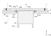
- Fig. 18 is an end view showing a negative electrode terminal 440 and a bus bar 10 according to the third embodiment.
- the negative electrode terminal 440 is an electrode terminal.
- the negative electrode terminal 440 has the same configuration as the negative electrode terminal 420 and is given the same reference numerals as the negative electrode terminal 420, and the description thereof is omitted.
- the negative electrode terminal 440 has different configuration from the negative electrode terminal 420 and is given a different reference numeral from the negative electrode terminal 420, and the description thereof is omitted.
- the negative terminal 440 is partially recessed in a direction away from the busbar 10 with respect to the surface P facing the busbar 10. As shown in FIG. 18, the negative terminal 440 includes a first member 441, a second member 422, and a third member 423.
- the first member 441 contains a first metal. That is, the first member 441 is formed from a material containing copper or a copper alloy.
- the first member 441 is partially recessed in the direction away from the busbar 10.
- the first member 441 includes a head 441a, a main body 421b, and legs 421c.
- the head 441a has a facing portion 441a1 that faces the busbar 10 along the height direction Z of the battery 1, and an outer peripheral portion 441a2 that faces the second member 422 along the longitudinal direction X and lateral direction Y of the battery 1.
- the head 441a has a shorter length along the stacking direction (height direction Z) than the head 421a of the first member 421. That is, in the first member 441, the head 441a is recessed in the direction away from the busbar 10. There is a gap between the first member 441 and the busbar 10.
- the negative terminal 440 is partially recessed in a direction away from the busbar 10. With this configuration, when the negative terminal 440 and the busbar 10 are joined, interference between the busbar 10 and the portion of the negative terminal 440 that is not actively joined to the busbar 10 can be suppressed.
- the portion of the negative terminal 440 that is electrically connected to the busbar 10 is the third member 423. Therefore, by partially recessing the first member 441 in a direction away from the busbar 10, interference between the first member 441 and the busbar 10 can be suppressed when the third member 423 and the busbar 10 are joined.
- the second member 442 may also be recessed in a direction away from the busbar 10. In this case, interference between the second member 442 and the busbar 10 can be suppressed when the third member 423 and the busbar 10 are joined.
- Fig. 19 is an end view showing the negative electrode terminal 450 and the bus bar 10 according to the fourth embodiment.
- the negative electrode terminal 450 is an electrode terminal.
- the negative electrode terminal 450 has the same configuration as the negative electrode terminal 420 and is given the same reference numerals as the negative electrode terminal 420, and the description thereof is omitted.
- the negative electrode terminal 450 has different configuration from the negative electrode terminal 420 and is given a different reference numeral from the negative electrode terminal 420, and the description thereof is omitted.
- the negative electrode terminal 450 includes a first member 451, a second member 422, and a third member 423.
- the first member 451 contains a first metal. That is, the first member 451 is formed from a material containing copper or a copper alloy.
- the first member 451 includes a head 451a, a main body 421b, and a leg 421c.
- the head 451a has a facing portion 451a1 that faces the busbar 10 along the height direction Z of the battery 1, and an outer peripheral portion 451a2 that faces the second member 422 along the longitudinal direction X and lateral direction Y of the battery 1.
- the head 451a has a recess 451a3.
- the recess 451a3 is a portion where the facing portion 451a1 of the first member 451 is partially recessed.
- the recess 451a3 of the first member 451 and the second member 422 are laser-joined from the side of the surface facing the busbar 10.
- the recess 451a3 is laser-joined to the facing portion 451a1 in an annular shape.
- the recess 451a3 may be laser-joined to the facing portion 451a1 in an arc shape. That is, the recess 451a3 may be intermittently laser-bonded to the opposing portion 451a1.
- the first member 451 and the second member 422 are laser-joined at the recess 451a3 of the first member 451 from the side of the surface P facing the busbar 10.
- the stiffness of the first member 451 can be maintained while the sputter generated during the laser joining is confined in the recess 451a3. Therefore, for example, when the first member 451 is crimped and joined to the negative current collector 220, deformation of the first member 451 can be suppressed.
- the recess 451a3 is preferably positioned outside the main body 421b. The stress generated when the first member 451 and the negative current collector 220 are crimped and joined can be suppressed from being transmitted to the recess 451a3.
- Fig. 20 is an end view showing the negative electrode terminal 460 and the bus bar 20 of the fifth embodiment.
- the negative electrode terminal 460 is an electrode terminal.
- the negative electrode terminal 460 has the same configuration as the negative electrode terminal 420 and is given the same reference numerals as the negative electrode terminal 420, and the description thereof is omitted.
- the negative electrode terminal 460 has different configuration from the negative electrode terminal 420 and is given a different reference numeral from the negative electrode terminal 420, and the description thereof is omitted.
- the negative terminal 460 partially protrudes beyond the opposing surface P of the busbar 20 in a direction approaching the busbar 20.
- the busbar 20 has a recess 20a that accommodates the first member 461 on the opposing surface P side.
- the negative terminal 460 includes a first member 451, a second member 422, and a third member 423.
- the first member 461 contains a first metal. That is, the first member 461 is formed from a material containing copper or a copper alloy.
- the first member 461 includes a head 461a, a main body 421b, and legs 421c.
- the head 461a has a facing portion 461a1 that faces the busbar 10 along the height direction Z of the battery 1, and an outer peripheral portion 461a2 that faces the second member 422 along the longitudinal direction X and lateral direction Y of the battery 1.
- the head 461a has a longer length along the stacking direction (height direction Z) than the head 421a of the first member 421. That is, in the first member 461, the head 461a protrudes in a direction approaching the recess 20a of the busbar 20.
- a gap is provided between the first member 461 and the recess 20a of the busbar 20. A gap does not have to be provided between the first member 461 and the recess 20a of the busbar 20.
- the negative electrode terminal 460 partially protrudes beyond the opposing surface P of the bus bar 20 in a direction approaching the bus bar 20 .
- the bus bar 20 includes a recess 20a that accommodates the first member 461.
- the second member 442 may also be protruded beyond the opposing surface P with the bus bar 20 in a direction approaching the bus bar 20.
- the bus bar 20 is configured to have a recess that accommodates the second member 442. In this case, interference between the second member 442 and the bus bar 20 can be suppressed when the third member 453 and the bus bar 20 are joined. In other words, the specifications and manufacturing errors of the second member 442 can be mitigated.
- Fig. 21 is an end view showing a negative electrode terminal 470 and a bus bar 10 according to the sixth embodiment.
- the negative electrode terminal 470 is an electrode terminal.
- the negative electrode terminal 470 has the same configuration as the negative electrode terminal 420 and is given the same reference numerals as the negative electrode terminal 420, and the description thereof is omitted.
- the negative electrode terminal 470 has different configuration from the negative electrode terminal 420 and is given a different reference numeral from the negative electrode terminal 420, and the description thereof is omitted.
- the negative electrode terminal 470 includes a first member 421, a second member 422, and a third member 423.
- the first member 421 and the second member 422 are crimped and joined.
- the first member 421 and the second member 422 may be crimped and then laser joined.
- the first member 421 and the second member 422 are joined by crimping. With this configuration, the first member 421 and the second member 422 can be joined by inputting mechanical stress to the first member 421 and the second member 422.
- the first member 421 and the second member 422 may be crimped and then laser-joined to each other. With this configuration, the first member 421 and the second member 422 can be joined more sufficiently.
- Fig. 22 is an end view showing a negative electrode terminal 480 and a bus bar 10 according to the seventh embodiment.
- the negative electrode terminal 480 is an electrode terminal.
- the negative electrode terminal 480 has the same configuration as the negative electrode terminal 420 and is given the same reference numerals as the negative electrode terminal 420, and the description thereof is omitted.
- the negative electrode terminal 480 has different configuration from the negative electrode terminal 420 and is given a different reference numeral from the negative electrode terminal 420, and the description thereof is omitted.
- the negative electrode terminal 480 includes a first member 421, a second member 482, and a third member 483.
- the second member 482 is joined to the first member 421.
- the second member 482 contains a first metal. That is, the second member 482 is formed of a material containing copper or a copper alloy.
- the second member 482 has a step portion 482b formed by partially recessing the side of the surface P facing the busbar 10.
- the second member 482 and the first member 421 are adjacent to each other in the stacking direction (height direction Z) via the step portion 482b. That is, the second member 482 and the first member 421 face each other in a direction intersecting the stacking direction (height direction Z).
- the thickness of the step portion 482b of the second member 482 in the stacking direction (height direction Z) corresponds to the thickness of the second member 422.
- the third member 483 is joined to the second member 482.
- the third member 483 contains a second metal. That is, the third member 483 is formed from a material containing aluminum or an aluminum alloy.
- the third member 483 is formed to be thinner than the third member 423 by the amount that the second member 482 is thicker than the second member 422.
- the outer shape of the third member 483 corresponds to the shape of the third member 423 made thinner in the stacking direction (height direction Z).
- the second member 482 and the first member 421 are adjacent to each other along the stacking direction (height direction Z). That is, the second member 482 and the first member 421 face each other in a direction intersecting the stacking direction (height direction Z).
- the second member 482 and the third member 483 made of a clad material, when the third member 483 is cut out to expose the second member 482, the second member 482 can be exposed without depending on the misalignment of the boundary surface between copper and aluminum in the clad material.
- this configuration corresponds to a configuration in which a part of the second member 482 is also cut out when the third member 483 is cut out, taking into account the misalignment of the boundary surface in the clad material. Therefore, the second member 482 and the first member 481 can be sufficiently joined without depending on the misalignment of the boundary surface of the clad material.
- Fig. 23 is a perspective view showing a cross section of the negative electrode terminal 490A of the eighth embodiment.
- Fig. 24 is an exploded perspective view of the negative electrode terminal 490A of Fig. 23.
- the negative electrode terminal 490A is an electrode terminal.
- the negative electrode terminal 490A has the same configuration as the negative electrode terminal 420, and the same reference numerals are used and the description is omitted.
- the negative electrode terminal 490A has a different configuration from the negative electrode terminal 420, and the description is omitted.
- the negative terminal 490A includes a first member 491, a pair of second members 492, and a third member 493.
- the first member 491 is electrically connected to the charge/discharge body 100 of the battery 1 via the negative electrode current collector 220.
- the first member 491 contains a first metal.
- the first member 491 is formed from a material containing copper or a copper alloy.
- the first member 491 includes a head 491a, a body 421b, and legs 421c, as shown in Figs. 23 and 24.
- the head 491a is formed in a plate shape, as shown in Fig. 24.
- the head 491a includes an opposing portion 491a1 that faces the busbar 10 along the height direction Z of the battery 1, as shown in Fig. 24.
- the head 491a includes an outer portion 491a2 that faces the second member 422 along the short-side direction Y of the battery 1, as shown in Fig. 24.
- the pair of second members 492 are joined to the first member 491 as shown in FIG. 23.
- the second members 492 contain a first metal. That is, the second members 492 are formed from a material containing copper or a copper alloy.
- the pair of second members 492 are formed in a rectangular column shape as shown in FIG. 24.
- the second member 492 has an opposing portion 492a that faces the busbar 10 along the height direction Z of the battery 1.
- the second member 492 contacts the outer portion 491a2 of the first member 491 along the short-side direction Y of the battery 1.
- the second member 492 is laser-joined to the first member 491 from the opposing surface P side along the boundary with the first member 491. That is, the second member 492 and the first member 491 are laser-joined in a butted state.
- the second member 492 and the first member 491 may be joined at points.
- the third member 493 is joined to the second member 492 as shown in FIG. 23.
- the third member 493 contains a second metal. That is, the third member 493 is formed from a material containing aluminum or an aluminum alloy.
- the third member 493 is interatomic-joined to the second member 492. That is, the third member 493 made of aluminum or the like and the second member 492 made of copper or the like are formed from a clad material.
- the third member 493 and the second member 492 may be joined by crimping.
- the third member 493 is formed in a plate shape as shown in FIG. 24.
- the third member 493 has a facing portion 493a that faces the busbar 10 along the height direction Z of the battery 1.
- the third member 493 has a concave recess 493b as shown in FIG. 24.
- the first member 491 and the second member 492 are attached to the recess 493b.
- the third member 493 has an insertion portion 493c that penetrates the recess 493b as shown in FIG. 24.
- the main body portion 421b of the first member 491 is inserted into the insertion portion 493c.
- the third member 493, the second member 492, and the first member 491 are adjacent to each other along the longitudinal direction X of the battery 1 on the side of the surface P facing the busbar 10 as shown in FIG. 23.
- the third member 493 is laser-joined to the busbar 10 on the side of the surface P facing the busbar 10.
- the third member 493 and the busbar 10 are laser-joined in a stacked state, i.e., overlapped state, along the height direction Z of the battery 1.
- the third member 493 is joined to the busbar 10 at two or more points straddling the first member 491 and the pair of second members 492 along a direction intersecting the height direction Z.
- the third member 493 and the busbar 10 are laser-joined in a line along the short side direction of the battery.
- the third member 493 and the busbar 10 may also be laser-joined in a point-like manner.
- the first member 491 and the second member 492 are electrically connected by laser welding through butt joints.
- the first member 491 and the second member 492 are not crimped.
- the second member 492 and the third member 493 are electrically connected by being made of clad material.
- the negative terminal 490A may have the first member 491 recessed in a direction away from the busbar 10, similar to the negative terminal 440 of the third embodiment.
- the negative terminal 490A may have the first member 491 protruding toward the busbar 20 beyond the opposing surface P with the busbar 20, similar to the negative terminal 460 of the fifth embodiment.
- Fig. 25 is a perspective view showing a cross section of a negative electrode terminal 490B according to a modification of the eighth embodiment.
- the negative electrode terminal 490B is an electrode terminal.
- the negative electrode terminal 490B has the same configuration as the negative electrode terminal 420 and the negative electrode terminal 490A, and is therefore given the same reference numerals as the negative electrode terminal 420 and the negative electrode terminal 490A, and the description thereof is omitted.
- the negative electrode terminal 490B has a different configuration from the negative electrode terminal 420 and the negative electrode terminal 490A, and is therefore given a different reference numeral from the negative electrode terminal 420 and the negative electrode terminal 490A, and is therefore described.
- the negative terminal 490A includes a first member 421, a second member 494, and a third member 493.
- the second member 494 is configured by making the shape of the second member 492 different.
- the outer shape of the second member 494 is formed into a plate shape that includes the outer shapes of the pair of second members 492.
- the inner shape of the second member 494 is the same as the second member 422 shown in FIG. 13.
- the second member 494 has an opposing portion 494a that faces the busbar 10 along the height direction Z of the battery 1.
- the first member 491 and the third member 493 are not crimped together. This configuration can prevent the negative terminal 490A from being affected by physical deformation of the first member 491 and the third member 493.
- the first member 421 and the third member 493 are not crimped together. This configuration can prevent the negative terminal 490B from being affected by physical deformation of the first member 421 and the third member 493.
- the configuration of the negative electrode terminal of the ninth embodiment corresponds to the configurations of all of the first to eighth embodiments except for the configuration of the fifth embodiment shown in FIG. 20 .
- the electrode terminal is applied to a configuration including, for example, the first member 421, the second member 422, and the third member 423 of the first embodiment shown in FIG. 16.
- the first member 421 does not protrude further toward the busbar 10 than the third member 423 on the side of the opposing surface P with the busbar 10.
- the first member 421 of the negative terminal is provided on the same plane as the third member 423 on the side of the opposing surface P with the busbar 10.
- On the same plane is defined taking into consideration the manufacturing tolerance of the external shapes of the first member 421 and the third member 423. In other words, on the same plane includes the case where the first member 421 protrudes from the third member 423 by several ⁇ m to several hundred ⁇ m.
- the third member 423 protrudes from the first member 421 by several ⁇ m to several hundred ⁇ m. "On the same plane" specifies the positional relationship between the first member 421 and the third member 423 such that the third member 423 and the bus bar 10 can be joined in a state in which they are at least partially in contact with each other. The third member 423 and the bus bar 10 are joined across the first member 421. The third member 423 and the bus bar 10 are joined across the second member 422.
- the electrode terminal is applied to a configuration including the first member 491, the second member 492, and the third member 493 of the eighth embodiment shown in, for example, FIG. 23 and FIG. 24.
- the first member 491 does not protrude further toward the busbar 10 than the third member 493 on the side of the surface P facing the busbar 10.
- the first member 491 of the negative terminal is provided on the same plane as the third member 493 on the side of the surface P facing the busbar 10. On the same plane is defined taking into consideration the manufacturing tolerance of the outer shapes of the first member 491 and the third member 493.
- the third member 493 and the busbar 10 are joined across the first member 491.
- the third member 493 and the busbar 10 are joined across a pair of second members 492.
- the third member 493 and the busbar 10 may be joined across one of the pair of second members 492.
- the negative terminal achieves the effects of some or all of the first to eighth embodiments, except for the fifth embodiment shown in FIG. 20.
- the battery of the present invention is not limited to the configurations described in the embodiments, and can be appropriately configured based on the contents described in the claims.
- the electrode terminal of the present invention can be constructed by any combination of the electrode terminal configurations of the first to eighth embodiments.
- the electrode terminal of the present invention is not limited to a negative electrode terminal.
- the electrode terminal of the present invention can be applied to a positive electrode terminal.
- the positive electrode terminal 410 which has been converted from a material containing aluminum to a material containing copper, can be sufficiently joined to the bus bar containing copper.
- the battery of the present invention is not limited to a lithium-ion battery.
- the battery of the present invention can be applied to, for example, nickel-metal hydride batteries and lead batteries.
- the battery of the present invention is not limited to a secondary battery.
- the battery of the present invention can be applied to a primary battery.
- the charging/discharging body of the battery of the present invention is not limited to a wound type charging/discharging body in which a positive electrode, a separator, and a negative electrode each formed in a long shape are bundled and wound.
- the charging/discharging body of the battery of the present invention can be a stacked type in which a positive electrode, a separator, and a negative electrode each formed in a rectangular shape are alternately stacked.
- the charging/discharging body of the battery of the present invention can be a stacked type in which a single separator formed in a long shape is alternately provided with a plurality of positive electrodes and a plurality of negative electrodes formed in a relatively short shape and facing each other through the separator. In such a charging/discharging body, the separator is folded and stacked, so that the positive electrode and the negative electrode face each other through the separator.
- the battery of the present invention is not limited to a configuration in which one charging/discharging body is provided.
- the battery of the present invention can be applied to a configuration in which two or more charging/discharging bodies are provided.
- the battery of the present invention is not limited to a configuration in which the charging/discharging body is sealed by a container and a lid.
- the battery of the present invention can be applied to a configuration in which the charge/discharge body is sealed with a laminate film.
Landscapes
- Chemical & Material Sciences (AREA)
- Chemical Kinetics & Catalysis (AREA)
- Electrochemistry (AREA)
- General Chemical & Material Sciences (AREA)
- Engineering & Computer Science (AREA)
- Manufacturing & Machinery (AREA)
- Inorganic Chemistry (AREA)
- Connection Of Batteries Or Terminals (AREA)
Priority Applications (5)
| Application Number | Priority Date | Filing Date | Title |
|---|---|---|---|
| US18/868,424 US20250337133A1 (en) | 2022-12-01 | 2022-12-01 | Electrode terminal and battery |
| EP22967223.3A EP4629430A1 (en) | 2022-12-01 | 2022-12-01 | Electrode terminal and battery |
| JP2024561116A JPWO2024116393A1 (https=) | 2022-12-01 | 2022-12-01 | |
| CN202280096392.9A CN119366054A (zh) | 2022-12-01 | 2022-12-01 | 电极端子和电池 |
| PCT/JP2022/044479 WO2024116393A1 (ja) | 2022-12-01 | 2022-12-01 | 電極端子及び電池 |
Applications Claiming Priority (1)
| Application Number | Priority Date | Filing Date | Title |
|---|---|---|---|
| PCT/JP2022/044479 WO2024116393A1 (ja) | 2022-12-01 | 2022-12-01 | 電極端子及び電池 |
Publications (1)
| Publication Number | Publication Date |
|---|---|
| WO2024116393A1 true WO2024116393A1 (ja) | 2024-06-06 |
Family
ID=91323160
Family Applications (1)
| Application Number | Title | Priority Date | Filing Date |
|---|---|---|---|
| PCT/JP2022/044479 Ceased WO2024116393A1 (ja) | 2022-12-01 | 2022-12-01 | 電極端子及び電池 |
Country Status (5)
| Country | Link |
|---|---|
| US (1) | US20250337133A1 (https=) |
| EP (1) | EP4629430A1 (https=) |
| JP (1) | JPWO2024116393A1 (https=) |
| CN (1) | CN119366054A (https=) |
| WO (1) | WO2024116393A1 (https=) |
Cited By (1)
| Publication number | Priority date | Publication date | Assignee | Title |
|---|---|---|---|---|
| WO2026058484A1 (ja) * | 2024-09-12 | 2026-03-19 | ビークルエナジージャパン株式会社 | 電極端子、電池、及び組電池 |
Citations (5)
| Publication number | Priority date | Publication date | Assignee | Title |
|---|---|---|---|---|
| WO2012169055A1 (ja) * | 2011-06-10 | 2012-12-13 | 日立ビークルエナジー株式会社 | 二次電池 |
| JP5656592B2 (ja) | 2010-12-06 | 2015-01-21 | 日立オートモティブシステムズ株式会社 | 二次電池 |
| JP2016207510A (ja) * | 2015-04-23 | 2016-12-08 | 日立オートモティブシステムズ株式会社 | 角形二次電池 |
| WO2018173586A1 (ja) * | 2017-03-24 | 2018-09-27 | 日立金属株式会社 | クラッド材の製造方法 |
| WO2021256462A1 (ja) * | 2020-06-16 | 2021-12-23 | 株式会社Gsユアサ | 蓄電素子 |
-
2022
- 2022-12-01 EP EP22967223.3A patent/EP4629430A1/en active Pending
- 2022-12-01 JP JP2024561116A patent/JPWO2024116393A1/ja active Pending
- 2022-12-01 CN CN202280096392.9A patent/CN119366054A/zh active Pending
- 2022-12-01 US US18/868,424 patent/US20250337133A1/en active Pending
- 2022-12-01 WO PCT/JP2022/044479 patent/WO2024116393A1/ja not_active Ceased
Patent Citations (5)
| Publication number | Priority date | Publication date | Assignee | Title |
|---|---|---|---|---|
| JP5656592B2 (ja) | 2010-12-06 | 2015-01-21 | 日立オートモティブシステムズ株式会社 | 二次電池 |
| WO2012169055A1 (ja) * | 2011-06-10 | 2012-12-13 | 日立ビークルエナジー株式会社 | 二次電池 |
| JP2016207510A (ja) * | 2015-04-23 | 2016-12-08 | 日立オートモティブシステムズ株式会社 | 角形二次電池 |
| WO2018173586A1 (ja) * | 2017-03-24 | 2018-09-27 | 日立金属株式会社 | クラッド材の製造方法 |
| WO2021256462A1 (ja) * | 2020-06-16 | 2021-12-23 | 株式会社Gsユアサ | 蓄電素子 |
Non-Patent Citations (1)
| Title |
|---|
| See also references of EP4629430A1 |
Cited By (1)
| Publication number | Priority date | Publication date | Assignee | Title |
|---|---|---|---|---|
| WO2026058484A1 (ja) * | 2024-09-12 | 2026-03-19 | ビークルエナジージャパン株式会社 | 電極端子、電池、及び組電池 |
Also Published As
| Publication number | Publication date |
|---|---|
| EP4629430A1 (en) | 2025-10-08 |
| US20250337133A1 (en) | 2025-10-30 |
| CN119366054A (zh) | 2025-01-24 |
| JPWO2024116393A1 (https=) | 2024-06-06 |
Similar Documents
| Publication | Publication Date | Title |
|---|---|---|
| EP4468506A1 (en) | Secondary battery | |
| KR101182904B1 (ko) | 전극 조립체와 이를 이용한 이차 전지 및 그 제조방법 | |
| JP7607214B2 (ja) | 蓄電装置 | |
| US9236595B2 (en) | Secondary battery | |
| JP4749130B2 (ja) | 二次電池及びその形成方法 | |
| KR20200141200A (ko) | 다층 구조의 전지케이스를 갖는 원통형 이차전지 및 그 제조방법 | |
| KR20130050070A (ko) | 이차 전지 | |
| KR102911702B1 (ko) | 원통형 이차 전지 | |
| EP4593166A1 (en) | Cylindrical secondary battery | |
| EP4593165A1 (en) | Cylindrical secondary battery | |
| US20200152923A1 (en) | Battery with external terminals | |
| WO2024116393A1 (ja) | 電極端子及び電池 | |
| US20240014473A1 (en) | Cylindrical battery | |
| JPWO2019116914A1 (ja) | 蓄電素子 | |
| JP7830495B2 (ja) | 電池及び電池の製造方法 | |
| US11699825B2 (en) | Secondary battery and method for manufacturing the same | |
| US10497924B2 (en) | Secondary battery | |
| WO2023037641A1 (ja) | 電池及び電池の製造方法 | |
| JP7285817B2 (ja) | 密閉型電池および密閉型電池の製造方法 | |
| WO2023054134A1 (ja) | 蓄電装置および蓄電装置の製造方法 | |
| JP7040060B2 (ja) | 蓄電素子 | |
| JP2022129822A (ja) | 電池 | |
| US20250007048A1 (en) | Secondary battery | |
| JP7772808B2 (ja) | 電池及び電池の製造方法 | |
| US20250239749A1 (en) | Battery and manufacturing method for battery |
Legal Events
| Date | Code | Title | Description |
|---|---|---|---|
| 121 | Ep: the epo has been informed by wipo that ep was designated in this application |
Ref document number: 22967223 Country of ref document: EP Kind code of ref document: A1 |
|
| WWE | Wipo information: entry into national phase |
Ref document number: 2024561116 Country of ref document: JP |
|
| WWE | Wipo information: entry into national phase |
Ref document number: 18868424 Country of ref document: US Ref document number: 202280096392.9 Country of ref document: CN |
|
| WWP | Wipo information: published in national office |
Ref document number: 202280096392.9 Country of ref document: CN |
|
| WWE | Wipo information: entry into national phase |
Ref document number: 2022967223 Country of ref document: EP |
|
| NENP | Non-entry into the national phase |
Ref country code: DE |
|
| ENP | Entry into the national phase |
Ref document number: 2022967223 Country of ref document: EP Effective date: 20250701 |
|
| WWP | Wipo information: published in national office |
Ref document number: 2022967223 Country of ref document: EP |
|
| WWP | Wipo information: published in national office |
Ref document number: 18868424 Country of ref document: US |