WO2024111374A1 - 更新管理装置、更新管理システム及びコンピュータプログラム - Google Patents
更新管理装置、更新管理システム及びコンピュータプログラム Download PDFInfo
- Publication number
- WO2024111374A1 WO2024111374A1 PCT/JP2023/039479 JP2023039479W WO2024111374A1 WO 2024111374 A1 WO2024111374 A1 WO 2024111374A1 JP 2023039479 W JP2023039479 W JP 2023039479W WO 2024111374 A1 WO2024111374 A1 WO 2024111374A1
- Authority
- WO
- WIPO (PCT)
- Prior art keywords
- software
- power supply
- state
- vehicle
- supply state
- Prior art date
- Legal status (The legal status is an assumption and is not a legal conclusion. Google has not performed a legal analysis and makes no representation as to the accuracy of the status listed.)
- Ceased
Links
Images




Classifications
-
- B—PERFORMING OPERATIONS; TRANSPORTING
- B60—VEHICLES IN GENERAL
- B60R—VEHICLES, VEHICLE FITTINGS, OR VEHICLE PARTS, NOT OTHERWISE PROVIDED FOR
- B60R16/00—Electric or fluid circuits specially adapted for vehicles and not otherwise provided for; Arrangement of elements of electric or fluid circuits specially adapted for vehicles and not otherwise provided for
- B60R16/02—Electric or fluid circuits specially adapted for vehicles and not otherwise provided for; Arrangement of elements of electric or fluid circuits specially adapted for vehicles and not otherwise provided for electric constitutive elements
-
- G—PHYSICS
- G06—COMPUTING OR CALCULATING; COUNTING
- G06F—ELECTRIC DIGITAL DATA PROCESSING
- G06F8/00—Arrangements for software engineering
- G06F8/60—Software deployment
- G06F8/65—Updates
- G06F8/654—Updates using techniques specially adapted for alterable solid state memories, e.g. for EEPROM or flash memories
Definitions
- This disclosure relates to an update management device, an update management system, and a computer program.
- This application claims priority to Japanese Application No. 2022-185655, filed on November 21, 2022, and incorporates all of the contents of said Japanese application by reference.
- ECUs Electronic Control Units
- vehicle power sources have become more complex and their power supply states have become more diverse.
- the opportunities for updating software installed in ECUs are also increasing.
- Patent Document 1 discloses a vehicle master device that acquires update data from an external source, instructs an ECU to be rewritten to install using the acquired update data, and distributes the acquired update data to the ECU to be rewritten.
- the vehicle master device includes an installation condition determination unit that determines whether or not all of the following conditions are met: a first condition that user consent to installation has been obtained, a second condition that data communication with a center device is possible, a third condition that the vehicle state is in a state where installation is possible, a fourth condition that the ECU to be rewritten is in a state where installation is possible, and a fifth condition that the update data is normal data; and an installation instruction unit that instructs the electronic control device to be rewritten to install using the update data when the installation condition determination unit determines that all of the first condition, the second condition, the third condition, the fourth condition, and the fifth condition are met.
- the update management device disclosed herein is an update management device that manages software updates for an in-vehicle device in a vehicle having a plurality of power states including a first power state and a second power state different from the first power state, and includes a receiving unit that receives, from an external device of the vehicle, first update data for updating a first software that operates in the first power state and the second power state, and second update data for updating a second software that does not operate in the first power state but operates in the second power state, a determining unit that determines whether the power state of the vehicle is the first power state or the second power state, and a first memory that, when the determining unit determines that the power state of the vehicle is the first power state, stores the first update data.
- an update management device comprising: a first transmission unit that transmits the first update data to the in-vehicle device so that the in-vehicle device, which has a first storage unit and a second storage unit, installs the updated first software in the first storage unit and activates the updated first software; and a second transmission unit that transmits the first update data and the second update data to the in-vehicle device so that the in-vehicle device installs the updated first software and the updated second software in the second storage unit and activates the updated first software and the updated second software when the determination unit determines that the power supply state of the vehicle is the second power supply state.
- the update management system disclosed herein is an update management system that includes an update management device that manages software updates for an in-vehicle device in a vehicle having a plurality of power states including a first power state and a second power state different from the first power state, and the in-vehicle device, and the update management device includes a receiving unit that receives, from an external device of the vehicle, first update data for updating first software that operates in the first power state and the second power state, and second update data for updating second software that does not operate in the first power state but operates in the second power state, and a receiving unit that receives, when the power state of the vehicle is the first power state, a determination unit that determines whether the power supply state of the vehicle is the second power supply state, a first storage unit that determines whether the power supply state of the vehicle is the first power supply state, and a first transmission unit that transmits the first update data to the in-vehicle device in order to activate the updated first software, and a first transmission unit that determines whether the power supply state of the
- a second transmission unit configured to transmit the first update data and the second update data to the in-vehicle device in order to activate the updated first software and the updated second software; a first instruction unit configured to transmit a first activation instruction to the in-vehicle device when the determination unit determines that the power supply state of the vehicle is the first power supply state, for activating the updated first software installed in the first storage unit; and a first instruction unit configured to transmit a first activation instruction to the in-vehicle device in order to activate the updated first software installed in the second storage unit, when the determination unit determines that the power supply state of the vehicle is the second power supply state.
- the update management system includes:
- the computer program disclosed herein is a computer program for controlling an update management device that manages software updates for an in-vehicle device in a vehicle having multiple power states including a first power state and a second power state different from the first power state, and includes a receiving step of receiving, from an external device of the vehicle, first update data for updating first software that operates in the first power state and the second power state, and second update data for updating second software that does not operate in the first power state but operates in the second power state, a determining step of determining whether the power state of the vehicle is the first power state or the second power state, and a second update step of determining, when it is determined that the power state of the vehicle is the first power state,
- a computer program for controlling an update management device comprising: a first transmission step in which the in-vehicle device, which has a first storage unit and a second storage unit, transmits the first update data to the in-vehicle device in order to install the updated first software in the first storage unit and activate the updated first software; and
- the update management device disclosed herein is an update management device that manages software updates for an in-vehicle device in a vehicle having multiple power states including a first power state and a second power state different from the first power state, and includes a receiving unit that receives from an external device of the vehicle first update data for updating a first software that operates in the first power state and the second power state, and second update data for updating a second software that does not operate in the first power state but operates in the second power state, a combining unit that creates combined update data from the first update data and the second update data to install combined software including a first function that is a function of the first software after the update and a second function that is a function of the second software after the update, and a transmitting unit that transmits the combined update data to the in-vehicle device so that the in-vehicle device, which has a memory unit, installs the combined software in the recording unit, and activates the first function when the power state of the vehicle is the first power state and activates the second function when the
- the update management system disclosed herein is an update management system that is provided in a vehicle having a plurality of power states including a first power state and a second power state different from the first power state, and that includes an update management device that manages software updates for an in-vehicle device and the in-vehicle device, the update management device including a receiving unit that receives from an external device of the vehicle first update data for updating a first software that operates in the first power state and the second power state, and second update data for updating a second software that does not operate in the first power state but operates in the second power state, a synthesis unit that creates synthetic update data from the first update data and the second update data to install synthetic software including a first function that is a function of the first software after the update and a second function that is a function of the second software after the update, and a memory unit that installs the synthetic software in the recording unit, and when the power state of the vehicle is the first power state, the update management device includes a receiving unit that receives from an external device of the vehicle
- the computer program disclosed herein is a computer program for controlling an update management device that manages software updates for an in-vehicle device in a vehicle having multiple power states including a first power state and a second power state different from the first power state, and includes a receiving step of receiving, from an external device of the vehicle, first update data for updating a first software that operates in the first power state and the second power state, and second update data for updating a second software that does not operate in the first power state but operates in the second power state; a combining step of creating, from the first update data and the second update data, composite update data for installing composite software including a first function that is a function of the first software after the update and a second function that is a function of the second software after the update; and a transmitting step of transmitting the composite update data to the in-vehicle device having a storage unit, so that the in-vehicle device installs the composite software in the recording unit and activates the first function when the power state of the vehicle is the first power state and activates the
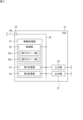
- FIG. 1 is a block diagram illustrating an example of an update management system.
- 2 is a block diagram showing an example of an internal configuration of an update management ECU;
- FIG. 2 is a block diagram showing an example of an internal configuration of an ECU.
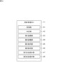
- FIG. 2 is a functional block diagram of an update management ECU according to the first embodiment.
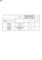
- 4 is a table showing an example of an ECU table in which ECUs are listed.
- 4 is a table showing an example of an ECU table in which ECUs are listed.
- 4 is a flowchart showing a control method according to the first embodiment.
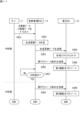
- FIG. 2 is a sequence diagram of the update management system according to the first embodiment.
- FIG. 11 is a sequence diagram of an update management system according to a second embodiment.
- a first ECU may be installed with first software that operates in the +B state and the IG state, and a second software that does not operate in the +B state but operates in the IG state, and a second ECU may be installed with third software that does not operate in the +B state but operates in the IG state, and a predetermined system may operate in cooperation with the second software and the third software.
- the first software and second software of the first ECU are updated by update data
- the first software and second software are installed on a single first ECU, so they can be activated even in the +B state.
- the second ECU has third software installed that operates in the IG state, so when the power state transitions to the IG state, the update data starts installing the third software, and the third software is activated. If the second software of the first ECU is already activated in the +B state, the second software may issue a command to the third software of the second ECU when the power state transitions to the IG state.
- the third software of the second ECU has only just started to be installed, so it may not understand the command issued by the second software of the first ECU, which could cause the specified system to not operate.
- Patent Document 1 works with one ECU, but cannot handle cases where a specific system operates in cooperation with multiple ECUs in a vehicle with multiple power supply states.
- the present disclosure can provide an update management device that installs and activates software in each ECU using update data, allowing a specified system to operate without any inconsistencies, even when multiple ECUs in a vehicle having multiple power states work together to operate functions.
- the gist of the present disclosure includes the following configurations.
- the update management device disclosed herein is an update management device that manages software updates for an in-vehicle device in a vehicle having a plurality of power states including a first power state and a second power state different from the first power state, and includes a receiving unit that receives, from an external device of the vehicle, first update data for updating a first software that operates in the first power state and the second power state, and second update data for updating a second software that does not operate in the first power state but operates in the second power state, a determining unit that determines whether the power state of the vehicle is the first power state or the second power state, and when the determining unit determines that the power state of the vehicle is the first power state,
- the update management device includes a first transmission unit that transmits the first update data to the in-vehicle device, the in-vehicle device having a first memory unit and a second memory unit, so that the in-vehicle device installs the updated first software in the first memory unit and activates the updated first software, and a second
- the update management device transmits update data to the in-vehicle device to alternately install and activate the software in the two storage units of the in-vehicle device depending on the power supply state of the vehicle.
- This allows the software of the in-vehicle device to be updated and activated sequentially at appropriate times depending on the power supply state, and the function in which the software of multiple ECUs operates in conjunction with each other works without any discrepancies.
- the update management device may further include a first instruction unit that transmits a first activation instruction to the in-vehicle device to activate the updated first software installed in the first storage unit when the determination unit determines that the power supply state of the vehicle is the first power supply state, and a second instruction unit that transmits a second activation instruction to the in-vehicle device to activate the updated first software and the updated second software installed in the second storage unit when the determination unit determines that the power supply state of the vehicle is the second power supply state.
- the update management device installs and activates software in the in-vehicle device using update data depending on the power supply state of the vehicle. This allows the software in the in-vehicle device to be updated and activated sequentially at appropriate times depending on the power supply state, and the function in which the software of multiple ECUs operates in conjunction with each other works without any discrepancies.
- the update management device may further include a first erasure instruction unit that transmits a first erasure instruction to the in-vehicle device to erase the pre-update first software and the pre-update second software from the second storage unit when the pre-update first software and the pre-update second software are installed in the second storage unit and the post-update first software is installed in the first storage unit, and a second erasure instruction unit that transmits a second erasure instruction to the in-vehicle device to erase the post-update first software from the first storage unit when the post-update first software is installed in the first storage unit and the post-update first software and the post-update second software are installed in the second storage unit.
- the update management device installs software in one of the storage units, activates it on the in-vehicle device, and then erases the software in the other storage unit. This makes the storage unit into which software will next be installed empty, allowing the next software to be installed, etc.
- the first power state may be a power state when the vehicle is in a state where it cannot run
- the second power state may be a power state when the vehicle is in a state where it can run.
- the update management device transmits update data for alternately installing and activating software in the two storage units of the in-vehicle device to the in-vehicle device according to the power state when the vehicle can be driven and the power state when the vehicle cannot be driven.
- This allows the software of the in-vehicle device to be updated and activated sequentially at appropriate times according to the power state, and the function of the software of multiple ECUs working in conjunction with each other works without any discrepancies.
- the receiving unit may receive the first update data and the second update data from the external device while the power state is the first power state.
- update data is downloaded to the update management device in the first power state, so that the software is quickly installed and activated after transitioning to the second power state.
- the update management system disclosed herein is an update management system including the update management device described in any one of (1) to (5) and the in-vehicle device.
- the update management system disclosed herein is an update management system that includes an update management device that manages software updates for an in-vehicle device in a vehicle having a plurality of power states including a first power state and a second power state different from the first power state, and the in-vehicle device, wherein the update management device includes a receiving unit that receives, from an external device of the vehicle, first update data for updating first software that operates in the first power state and the second power state, and second update data for updating second software that does not operate in the first power state but operates in the second power state, and a receiving unit that receives, when the power state of the vehicle is the first power state, first update data for updating the first software that operates in the first power state and the second power state, from an external device of the vehicle.
- a determination unit that determines whether the power supply state of the vehicle is the first power supply state or the second power supply state; a first storage unit and a second storage unit that, when the determination unit determines that the power supply state of the vehicle is the first power supply state, installs the updated first software into the first storage unit and transmits the first update data to the in-vehicle device in order to activate the updated first software; and a first transmission unit that, when the determination unit determines that the power supply state of the vehicle is the second power supply state, installs the updated first software and the updated second software into the second storage unit.
- a second transmission unit that transmits the first update data and the second update data to the in-vehicle device in order to activate the updated first software and the updated second software; a first instruction unit that transmits a first activation instruction to the in-vehicle device when the determination unit determines that the power supply state of the vehicle is the first power supply state, to activate the updated first software installed in the first storage unit; and a first instruction unit that transmits a first activation instruction to the in-vehicle device in order to activate the updated first software installed in the second storage unit, when the determination unit determines that the power supply state of the vehicle is the second power supply state.
- the in-vehicle device is an update management system that includes a first activation unit that activates the updated first software installed in the first storage unit when the first activation instruction is received, and a second activation unit that activates the updated first software and the updated second software installed in the second storage unit when the second activation instruction is received.
- the update management device transmits update data to the in-vehicle device for alternately installing and activating the software in the two storage units of the in-vehicle device.
- the in-vehicle device installs and activates the software according to the power supply state of the vehicle using the transmitted update data. This allows the software of the in-vehicle device to be sequentially updated and activated at appropriate times according to the power supply state, and the function of the software of multiple ECUs working in conjunction with each other operates without discrepancies.
- the update management system may further include a first erasure unit that erases the first software before the update and the second software before the update from the second storage unit when the first software is installed in the first storage unit, and a second erasure unit that erases the first software before the update and the second software before the update from the second storage unit when the updated first software is installed in the first storage unit, and a second erasure unit that erases the updated first software from the first storage unit when the updated first software and the updated second software are installed in the second storage unit.
- the update management system installs software in one of the storage units of the in-vehicle device, activates the in-vehicle device, and then erases the software in the other storage unit. This empties the storage unit of the in-vehicle device into which software will next be installed, making it possible to install the software next.
- the computer program disclosed herein is a computer program for controlling an update management device that manages software updates of an in-vehicle device in a vehicle having multiple power states including a first power state and a second power state different from the first power state, and includes a receiving step of receiving, from an external device of the vehicle, first update data for updating first software that operates in the first power state and the second power state, and second update data for updating second software that does not operate in the first power state but operates in the second power state, a determination step of determining whether the power state of the vehicle is the first power state or the second power state, and when it is determined that the power state of the vehicle is the first power state,
- a computer program for controlling an update management device comprising: a first transmission step in which the in-vehicle device, which has a first storage unit and a second storage unit, transmits the first update data to the in-vehicle device in order to install the updated first software in the first storage unit and activate the updated first software; and a second transmission step in which, when the power
- the update management device transmits update data to the in-vehicle device to alternately install and activate the software in the two storage units of the in-vehicle device depending on the power supply state of the vehicle.
- This allows the software of the in-vehicle device to be updated and activated sequentially at appropriate times depending on the power supply state, and the function in which the software of multiple ECUs operates in conjunction with each other works without any discrepancies.
- the update management device disclosed herein is an update management device that manages software updates for an in-vehicle device in a vehicle having multiple power states including a first power state and a second power state different from the first power state, and includes a receiving unit that receives from an external device of the vehicle first update data for updating a first software that operates in the first power state and the second power state, and second update data for updating a second software that does not operate in the first power state but operates in the second power state, a combining unit that creates combined update data from the first update data and the second update data to install combined software including a first function that is a function of the first software after the update and a second function that is a function of the second software after the update, and a transmitting unit that transmits the combined update data to the in-vehicle device so that the in-vehicle device having a memory unit installs the combined software in the recording unit, and activates the first function when the power state of the vehicle is the first power state and activates the second function when the power state
- the update management device creates composite update data from the two update data for updating the two pieces of software, installs it in the storage unit of the in-vehicle device, and transmits the update data to the in-vehicle device for activation according to the vehicle's power supply state.
- This allows the software in the in-vehicle device to be updated and activated sequentially at appropriate times according to the power supply state, and the function of the software of multiple ECUs working in conjunction with each other to operate without any discrepancies.
- the update management device may further include a determination unit that determines whether the power supply state of the vehicle is the first power supply state or the second power supply state, a first instruction unit that transmits a first activation instruction to the in-vehicle device to activate the first function when the determination unit determines that the power supply state of the vehicle is the first power supply state, and a second instruction unit that transmits a second activation instruction to the in-vehicle device to activate the second function when the determination unit determines that the power supply state of the vehicle is the second power supply state.
- the update management device activates the software in the in-vehicle device according to the power supply state of the vehicle. This allows the software in the in-vehicle device to be updated and activated sequentially at the appropriate time according to the power supply state, and the function in which the software of multiple ECUs operates in conjunction with each other works without any discrepancies.
- the determination unit when the determination unit determines that the power supply state of the vehicle is the first power supply state, the determination unit stores information indicating the first power supply state in a state storage unit that stores information indicating a power supply state, and when the determination unit determines that the power supply state of the vehicle is the second power supply state, the determination unit stores information indicating the second power supply state in the state storage unit, the first instruction unit refers to the state storage unit and, when the information indicating the first power supply state is stored, transmits the first activation instruction to the in-vehicle device, and the second instruction unit refers to the state storage unit and, when the information indicating the second power supply state is stored, transmits the second activation instruction to the in-vehicle device.
- the update management device activates software in the in-vehicle device based on information indicating the vehicle's power supply state. This allows the software in the in-vehicle device to be updated and activated sequentially at appropriate times according to the power supply state, and the function in which the software of multiple ECUs operates in conjunction with each other works without any discrepancies.
- the first power state may be a power state when the vehicle is in a state where it cannot run
- the second power state may be a power state when the vehicle is in a state where it can run.
- the update management device creates composite update data from the two update data for updating the two pieces of software, installs it in the storage unit of the in-vehicle device, and transmits the update data to the in-vehicle device for activation according to the vehicle's power supply state.
- This allows the software in the in-vehicle device to be updated and activated sequentially at appropriate times according to the power supply state, ensuring that the function of the software of multiple ECUs working in conjunction with each other operates without discrepancies.
- the receiving unit may receive the first update data and the second update data from the external device while the power state is the first power state.
- update data is downloaded to the update management device in the first power state, so that the software is quickly installed and activated after transitioning to the second power state.
- the update management system disclosed herein is an update management system that includes any one of the update management devices (10) to (14) and the in-vehicle device.
- An update management system is an update management system for a vehicle having a plurality of power states including a first power state and a second power state different from the first power state, the update management system including an update management device for managing software updates of an in-vehicle device and the in-vehicle device, the update management device including a receiving unit that receives, from an external device of the vehicle, first update data for updating first software that operates in the first power state and the second power state, and second update data for updating second software that does not operate in the first power state but operates in the second power state, and a receiving unit that receives, from the first update data and the second update data, a first function that is a function of the first software after the update and a second function that is a function of the second software after the update.
- a combining unit that creates combined update data for installing combined software including a first function and a second function
- a transmitting unit that transmits the combined update data to the in-vehicle device so that the in-vehicle device having a storage unit installs the combined software in the recording unit, activates the first function when the power supply state of the vehicle is the first power supply state, and activates the second function when the power supply state of the vehicle is the second power supply state
- a determining unit that determines whether the power supply state of the vehicle is the first power supply state or the second power supply state
- a first instruction unit that transmits a first activation instruction to the in-vehicle device to activate the first function when the determining unit determines that the power supply state of the vehicle is the first power supply state.
- an update management system that includes a second instruction unit that transmits a second activation instruction to the in-vehicle device for activating the second function when the determination unit determines that the power supply state of the vehicle is the second power supply state, and the in-vehicle device includes a first activation unit that activates the first function when the first activation instruction is received, and a second activation unit that activates the second function when the second activation instruction is received.
- the update management device creates composite update data from the two update data for updating the two pieces of software, installs it in the storage unit of the in-vehicle device, and transmits the update data to the in-vehicle device for activation according to the vehicle's power supply state.
- the update management device then sends an activation instruction to the in-vehicle device according to the vehicle's power supply state, and the in-vehicle device activates the software.
- the software in the in-vehicle device is updated and activated sequentially at appropriate times according to the power supply state, and the function of the software of multiple ECUs working in conjunction with each other operates without any discrepancies.
- the determination unit determines that the power supply state of the vehicle is the first power supply state, it stores information indicating the first power supply state in a state storage unit that stores information indicating a power supply state, and when the determination unit determines that the power supply state of the vehicle is the second power supply state, it stores information indicating the second power supply state in the state storage unit, and the first instruction unit may refer to the state storage unit and, when the information indicating the first power supply state is stored, transmit the first activation instruction to the in-vehicle device, and the second instruction unit may refer to the state storage unit and, when the information indicating the second power supply state is stored, transmit the second activation instruction to the in-vehicle device.
- the update management device activates software in the in-vehicle device based on information indicating the vehicle's power supply state. This allows the software in the in-vehicle device to be updated and activated sequentially at appropriate times according to the power supply state, and the function in which the software of multiple ECUs operates in conjunction with each other works without any discrepancies.
- the computer program disclosed herein is a computer program for controlling an update management device that manages software updates of an in-vehicle device in a vehicle having a plurality of power states including a first power state and a second power state different from the first power state, and includes a receiving step of receiving, from an external device of the vehicle, first update data for updating a first software that operates in the first power state and the second power state, and second update data for updating a second software that does not operate in the first power state but operates in the second power state; a combining step of creating, from the first update data and the second update data, combined update data for installing combined software including a first function that is a function of the first software after the update and a second function that is a function of the second software after the update; and a transmitting step of transmitting the combined update data to the in-vehicle device having a storage unit, so that the combined software is installed in the recording unit, and the first function is activated when the power state of the vehicle is the first power state, and the second function
- the update management device creates composite update data from the two update data for updating the two pieces of software, installs it in the storage unit of the in-vehicle device, and transmits the update data to the in-vehicle device for activation according to the vehicle's power supply state.
- This allows the software in the in-vehicle device to be updated and activated sequentially at appropriate times according to the power supply state, and the function of the software of multiple ECUs working in conjunction with each other to operate without any discrepancies.
- FIG. 1 is a diagram showing an example of the configuration of an update management system 1 according to the present invention.
- the update management system 1 is a system installed in a vehicle such as an automobile, etc.
- the update management system 1 includes an update management ECU 11, a first ECU 12, a second ECU 13, communication buses 14a and 14b, and a communication device 15.
- the update management ECU 11 is an update management device that manages software updates of in-vehicle devices in a vehicle having a plurality of power supply states including a first power supply state and a second power supply state different from the first power supply state.
- the first power supply state is, for example, a power supply state when the vehicle is in a state in which it cannot run
- the second power supply state is a power supply state when the vehicle is in a state in which it can run.
- the first power state is, for example, a power state when a key switch for starting an engine by inserting a key is in the OFF position.
- the first power state is a state in which power is not supplied from the vehicle battery to most of the electrical devices in the vehicle, but is supplied directly only to the minimum necessary in-vehicle devices. Examples of the few electrical devices include a security system and a clock.
- the first power state may be referred to as a +B state.
- the second power state is, for example, a power state when a key switch for starting the engine is in the ignition position.
- the second power state is a state in which power is supplied to all electrical devices and the vehicle starts moving when the accelerator is depressed.
- the second power state may be referred to as the IG state.
- the power supply state of the vehicle will be described as being of two types, a first power supply state and a second power supply state, but the power supply state is not limited to this and may be further subdivided.
- the in-vehicle device may be referred to as an ECU.
- the update management ECU 11 manages software updates for on-board devices in a vehicle that has multiple power supply states. For this reason, the update management ECU 11 is configured to operate in a power supply state in which software updates are performed. For example, the update management ECU 11 can operate in the +B state and the IG state.
- the update management ECU 11 functions, for example, as an integrated ECU that manages the first ECU 12 and the second ECU 13.
- the update management ECU 11 may transmit to the first ECU 12 and the second ECU 13 update data downloaded from a server 2, which is an external device outside the vehicle and connected via a network 3, for example.
- the update management ECU 11 may function as a GW-ECU (Gateway-ECU) that relays data transmitted and received between the first ECU 12 and the second ECU 13 and the communication device 15.
- GW-ECU Gateway-ECU
- the internal configuration of the update management ECU 11 will be described later.
- the communication device 15 is, for example, a communication interface that performs wireless communication.
- the communication device 15 communicates with the server 2 via a network 3 such as the Internet.
- the communication device 15 is a TCU (Telematics Communication Unit).
- the communication device 15 transmits data output from the update management ECU 11 to the server 2 via the network 3.
- the communication device 15 also receives data (such as update data) transmitted from the server 2 via the network 3.
- the communication device 15 transmits the data to the update management ECU 11 via the communication bus 14a.
- the server 2 is a device installed outside the vehicle.
- the server 2 is, for example, a server equipped with a control unit, a memory unit, and a communication unit (not shown).
- the memory unit of the server 2 stores, for example, programs or data for controlling each unit of the update management system 1 (for example, the update management ECU 11, the first ECU 12, the second ECU 13).
- the manufacturer of the first ECU 12 and the second ECU 13 updates the programs or data as necessary, and stores the updated programs or data in the memory unit of the server 2 as needed.
- the control unit of the server 2 uses the communication unit to transmit the updated programs or data to the update management ECU 11 as update data.
- the communication buses 14a and 14b are in-vehicle communication networks connected to the update management ECU 11.
- Various devices such as the first ECU 12, the second ECU 13, and the communication device 15
- the communication buses 14a and 14b extend from the update management ECU 11.
- two communication buses 14a and 14b extend from the update management ECU 11, but the number of communication buses is not particularly limited.
- the communication buses 14a and 14b are compliant with, for example, a communication protocol such as CAN (Controller Area Network), Ethernet (registered trademark), or FlexRay (registered trademark), but are not limited to these.
- the update management ECU 11 is connected to the first ECU 12 and the second ECU 13 via the communication bus 14b.
- the update management ECU 11 is connected to the first ECU 12 and the second ECU 13 via the communication bus 14b.
- the number of ECUs included in the update management system 1 is not particularly limited as long as it is two or more.
- the ECUs are, for example, devices (operation system ECUs) that control various parts of the vehicle (e.g., braking system, doors, battery, air conditioner, etc.).
- the multiple ECUs may each have different functions or each have the same functions.
- the first ECU 12 is an ECU in which a first software that operates in the +B state and the IG state, and a second software that does not operate in the +B state but operates in the IG state are installed.
- the internal configuration of the first ECU 12 will be described later. Note that the software that operates in the +B state and the IG state is sometimes called +B software, and the software that does not operate in the +B state but operates in the IG state is sometimes called IG software.
- the second ECU 13 is an ECU in which IG drive software is installed.
- the internal configuration of the second ECU 13 will be described later.
- FIG. 2 is a diagram showing an example of the internal configuration of the update management ECU 11.
- the update management ECU 11 includes an information processing unit 21 including a control unit 22 and a storage unit 23, and a plurality of transceivers 25a, 25b. These units are electrically connected to each other via an internal bus 24.
- the control unit 22 includes, for example, one or more CPUs (Central Processing Units), but is not limited to this. In the case of a CPU, the control unit 22 reads out computer programs stored in the memory unit 23 and executes various calculations and controls.
- CPUs Central Processing Units
- the storage unit 23 has a volatile memory and a non-volatile memory, and stores various data.
- the volatile memory includes, for example, a RAM (Random Access Memory).
- the non-volatile memory includes, for example, a flash memory, a HDD (Hard Disk Drive), a SSD (Solid State Drive), or a ROM (Read Only Memory). A part of the non-volatile memory may be provided outside the update management ECU 11.
- the storage unit 23 stores, for example, computer programs, various parameters, and tables in a non-volatile memory. Note that the storage unit 23 stores, for example, computer programs, various parameters, and tables downloaded from the server 2 via the network 3 and the communication device 15.
- transceivers 25a, 25b transmit and receive signals flowing through communication buses 14a, 14b via their respective ports (not shown).
- the transceivers 25a, 25b send information contained in the received signals to the control unit 22 via the internal bus 24.
- the transceivers 25a, 25b receive information sent by the control unit 22 via the internal bus 24 and transmit it to the communication buses 14a, 14b.
- the transceiver 25a is connected to the communication bus 14a, and the transceiver 25b is connected to the communication bus 14b.
- the control unit 22 of the information processing unit 21 includes a CPU, but this is not limited to this.
- the information processing unit 21 may be an FPGA (Field Programmable Gate Array), an ASIC (Application Specific Integrated Circuit), etc.
- FPGA Field Programmable Gate Array
- ASIC Application Specific Integrated Circuit
- the information processing unit 21 executes various calculations and control using a pre-programmed configuration.
- the information processing unit 21 executes various calculations and control using a configuration built in at the time of manufacture.
- FIG. 3 Internal configuration of the ECU] 3 is a diagram showing an example of the internal configuration of the first ECU 12.
- the internal configuration of the second ECU 13 is similar to that of the first ECU 12, and therefore a description thereof will be omitted.
- the first ECU 12 includes an information processing unit 31 including a control unit 32, a first memory unit 33, and a second memory unit 34, a transceiver 35, an input unit 36, and an output unit 37.
- the transceiver 35 is electrically connected to the information processing unit 31 via an internal bus 38.
- the control unit 32 includes, for example, one or more CPUs, but is not limited to this.
- a CPU for example, it reads out a computer program stored in the first storage unit 33 or the second storage unit 34, and executes various calculations and controls.
- the first storage unit 33 and the second storage unit 34 have a volatile memory and a non-volatile memory, similar to the storage unit 23, and store various data.
- the first storage unit 33 stores, for example, a computer program, various parameters, and tables in a non-volatile memory.
- the first storage unit 33 and the second storage unit 34 are one bank in which a physical memory is divided into several banks.
- the information processing unit 31 may further include a bank register (not shown) for switching banks.
- the bank register is configured so that when 0 is written to the bank register, the first storage unit 33 becomes accessible, and when 1 is written to the bank register, the second storage unit becomes accessible.
- first storage unit and the second storage unit may be the same storage unit, and, for example, the physical memory may be divided into several address spaces, and the memory in the first address space may be the first storage unit 33, and the memory in the second address space may be the second storage unit 34.
- the transceiver 35 is, for example, an integrated circuit (IC), such as a CAN transceiver.
- IC integrated circuit
- the transceiver 35 is connected to the communication bus 14b and receives various control messages from the communication bus 14b.
- the transceiver 35 includes a transmission circuit and a reception circuit (not shown).
- the transmission circuit and reception circuit communicate in accordance with the communication protocol of the communication bus 14b.
- the transmission circuit converts the digital signal data output by the information processing unit 31 into a specified analog signal and sends it to the communication bus 14b.
- the reception circuit converts the analog signal input from the communication bus 14b into a digital signal that can be read by the information processing unit 31 and outputs the digital signal to the information processing unit 31.
- the input unit 36 is connected to, for example, sensors, input devices, etc.
- the input unit 36 receives signals corresponding to the state of the vehicle and signals corresponding to instructions from the driver, etc.
- sensors include a temperature sensor that detects the temperature inside the vehicle, and a door switch that detects whether the door is closed, etc.
- input devices include a switch for operating the air conditioner, etc.
- the output unit 37 is connected to, for example, a motor, a solenoid, etc.
- the output unit 37 drives the connected motor, solenoid, etc. based on information sent by the information processing unit 31.
- the information is, for example, information indicating the movement of the connected motor, etc.
- the motor is, for example, a motor that raises and lowers a door window.
- the solenoid is, for example, a solenoid that locks a door.
- the first software and second software of the first ECU are updated by update data
- the first software and second software are installed on a single first ECU, so they can be activated even in the +B state.
- the second ECU has third software installed that operates in the IG state, so when the power state transitions to the IG state, the update data starts installation of the third software, and the third software is activated.
- the second software may issue a command to the third software of the second ECU when the power state transitions to the IG state.
- the third software of the second ECU since the third software of the second ECU has only just started to be installed, it may not understand the command issued by the second software of the first ECU, which could cause the specified system to not operate.
- the first ECU is a door ECU
- the second ECU is a sensor ECU.
- the first software is door lock software for controlling door locks
- the second software is window software for controlling power windows
- the third software is raindrop detection software for a sensor that detects raindrops.
- the specified system is a rainy weather window closing system that closes the windows when it rains.
- the door lock software and window software in the door ECU are updated with update data
- the door lock software and window software can be activated even in the +B state because they are installed in the door ECU.
- the sensor ECU has rain detection software installed that operates in the IG state, so when the power state transitions to the IG state, the rain detection software begins to be installed by the update data and is activated. Since the window software in the door ECU is already activated in the +B state, the window software may issue a command to the rain detection software in the sensor ECU when the power state transitions to the IG state.
- the rain detection software in the sensor ECU since the rain detection software in the sensor ECU has only just started to be installed, it may not understand the command issued by the window software in the door ECU, and the rainy weather window closing system may not work. For example, there is a risk that the window may not close in rainy weather.
- Fig. 4 is a functional block diagram showing functions included in the update management ECU 11 according to the first embodiment.
- Figs. 5 and 6 are tables showing an example of an ECU table listing ECUs.
- the update management ECU 11 includes a receiving unit 41, a determining unit 42, a first transmitting unit 43, a second transmitting unit 44, a first instruction unit 45, a second instruction unit 46, a first erasure instruction unit 47, and a second erasure instruction unit 48.
- "R" shown in Figs. 5 and 6 indicates that the system or software operates in that power state.
- the receiving unit 41 receives, from an external device of the vehicle, first update data for updating first software that operates in the first power supply state and the second power supply state, and second update data for updating second software that does not operate in the first power supply state but operates in the second power supply state.
- the receiving unit 41 has a function of downloading the first update data and the second data from the server 2.
- the server 2 is provided, for example, in a data center of a vehicle manufacturer.
- the server 2 stores, for example, update data for updating the software of each ECU.
- the first update data is update data for installing door lock software, which is the +B software of the first ECU 12.
- the second update data is update data for installing window software, which is the IG software of the first ECU 12.
- the receiving unit 41 operates the control unit 22 to access the server 2 via the internal bus 24, the transceiver 25a, the communication device 15, and the network 3, and downloads the update data stored in the server 2.
- the download is started, for example, when new update data is recorded in the server 2.
- the server 2 transmits information indicating that new update data has been recorded to each update management system 1.
- the information indicating that new update data has been recorded may include information indicating the version of the newly recorded update data.
- the information indicating that new update data has been recorded is referred to as update software information.
- an example of new update data being recorded in the server 2 is when the wind software of the first ECU 12 and the raindrop detection software of the second ECU 13 are updated to realize a rainy weather window-close system due to improved rain sensitivity compared to the previous rain sensor.
- Figure 6 is another example of an ECU table.
- the specified system is, for example, a keyless entry system.
- the ECU and software that executes the specified system are, for example, door lock software in the door ECU and software in the ECU that links with this. Since the keyless entry system operates in the +B state, the software in each ECU also operates in the +B state.
- the receiving unit 41 compares the version information included in the update software information sent from the server with the version information recorded in the ECU table to determine whether the software has been updated. If it is determined that the software has been updated, the receiving unit 41 requests the update data from the server 2 and downloads it. The receiving unit 41, for example, temporarily records the downloaded update data in the memory unit 23.
- the receiving unit 41 may receive the first update data and the second update data from an external device while the power supply state is the first power supply state.
- update data for updating door lock software which is +B software
- window software which is IG software
- the determination unit 42 has a function of determining whether the power supply state of the vehicle is the first power supply state or the second power supply state.
- the determination unit 42 detects the power supply state of the vehicle and determines whether the detected power supply state is +B state or IG state.
- the detection of the power supply state of the vehicle may be performed by the update management ECU 11 or a power supply monitoring ECU (not shown) that monitors the power supply state of the vehicle.
- +B state for example, the voltage of a power supply bus connected to an electrical device that is directly supplied with power from the vehicle's battery is detected, and if it is equal to or higher than a predetermined voltage, it is determined to be in +B state.
- IG state for example, the voltage of a power supply bus that supplies power to an ECU that operates when the vehicle starts moving when the accelerator is depressed, for example, an engine control ECU, is detected, and if it is equal to or higher than a predetermined voltage, it is determined to be in IG state. Note that if it is in +B state and IG state, it is determined to be in IG state.
- the first transmission unit has a function of transmitting the first update data to the in-vehicle device, which has a first memory unit and a second memory unit, when the determination unit determines that the power supply state of the vehicle is the first power supply state, so that the in-vehicle device installs the updated first software into the first memory unit and activates the updated first software.
- the first transmission unit 43 transmits update data for installing the door lock software, which is the +B software, to the door ECU, which is the first ECU 12.
- the first transmission unit 43 operates the control unit 22 to execute the function of the first transmission unit 43.
- the control unit 22 reads out the first update data that was temporarily stored.
- the control unit 22 transmits the read out first update data to the communication bus 14b via the transceiver 25b.
- the first update data transmitted to the communication bus 14b reaches the transceiver 35 of the first ECU 12.
- the first ECU 12 is operated by the control unit 32, and the control unit 32 receives the arrived update data via the transceiver 35.
- the control unit 32 temporarily stores the received update data in the first memory unit 33 or a RAM (Random Access Memory) (not shown).
- the first ECU 12 When the first transmission unit 43 transmits the first update data, the first ECU 12 installs the +B software into the first storage unit 33 based on the received first update data. For example, the door ECU installs door lock software into the first storage unit 33.
- the control unit 32 of the first ECU 12 is configured to install software into the first storage unit 33 based on the temporarily stored update data.
- the update management ECU 11 transmits to the first ECU 12 a first installation instruction, which is an instruction to install the +B software in the first storage unit 33 using the first update data.
- the first ECU 12 is configured to receive the first installation instruction and install the +B software.
- the second transmission unit has a function of transmitting the first update data and the second update data to the in-vehicle device so that, when the determination unit determines that the power supply state of the vehicle is the second power supply state, the in-vehicle device installs the updated first software and the updated second software into the second memory unit and activates the updated first software and the updated second software.
- the second transmission unit 44 transmits the first update data and the second update data for installing the door lock software, which is the +B software, and the window software, which is the IG software, to the door ECU, which is the first ECU 12.
- the second transmission unit 44 operates the control unit 22 to execute the function of the second transmission unit 44.
- the control unit 22 reads out the first update data that was temporarily stored in the memory unit 23.
- the control unit 22 transmits the read out first update data to the communication bus 14b via the transceiver 25b.
- the first update data transmitted to the communication bus 14b reaches the transceiver 35 of the first ECU 12.
- the first ECU 12 is operated by the control unit 32, and the control unit 32 receives the arrived update data via the transceiver 35.
- the control unit 32 stores the temporarily received update data in the first memory unit 33 or a RAM (not shown).
- the first ECU 12 installs the +B software and the IG software in the second storage unit 34 based on the received first update data and second update data. For example, the door ECU installs door lock software and window software in the second storage unit 34.
- the first ECU 12 When the first update data and the second update data are sent from the second transmission unit 44, the first ECU 12, for example, temporarily stores the sent first update data and second update data in the second storage unit 34. After the reception of the sent update data is completed, the control unit 32 of the first ECU 12 may be configured to install software based on the update data temporarily stored in the second storage unit 34.
- the update management ECU 11 transmits to the first ECU 12 a second installation instruction, which is an instruction to install the +B software and the IG software in the second storage unit 34 using the first update data and the second update data.
- the first ECU 12 that receives the second installation instruction may then be configured to install the +B software and the IG software.
- the first instruction unit 45 has a function of transmitting a first activation instruction to the in-vehicle device for activating the updated first software installed in the first memory unit when the determination unit determines that the power supply state of the vehicle is the first power supply state.
- the first instruction unit 45 transmits an activation instruction to activate the door lock software, which is the +B software.
- the first instruction unit 45 refers to the ECU table stored in the memory unit 23, for example, the contents as shown in FIG. 5 and FIG. 6. From the referred ECU table, the first instruction unit 45 obtains information indicating in which power state the system is executed by the software that operates. In the example of FIG. 6, the door lock software that executes the keyless entry system operates in both the +B state and the IG state, so when the power state is the +B state, the first instruction unit 45 transmits a first activation instruction to the door ECU to activate the updated door lock software installed in the first memory unit 33. On the other hand, since the +B software is not listed in FIG. 5, the first instruction unit 45 does not transmit the first activation instruction.
- the first activation instruction may be sent to the in-vehicle device after the software has been installed by the update data. This is because the software cannot be activated during installation.
- the first instruction unit 45 is configured to wait for the transmission for a predetermined period of time.
- the in-vehicle device is configured to send installation completion information, which is information indicating that the software installation has been completed, to the update management device after the software installation is completed. Then, when the installation completion information is received, the first instruction unit 45 is configured to send the first activation instruction.
- the first ECU 12 when the first ECU 12 receives a first activation instruction sent by the first instruction unit 45, the first ECU 12 is configured to operate the control unit 32 (first activation unit 32a) to activate the first software installed in the first storage unit 33.
- the second instruction unit 46 has a function of transmitting a second activation instruction to the in-vehicle device for activating the updated first software and the updated second software installed in the second memory unit when the determination unit determines that the power supply state of the vehicle is the second power supply state.
- the second instruction unit 46 transmits a second activation instruction to the door ECU to activate the window software, which is the IG software, for the rainy weather window close system. In addition, the second instruction unit 46 transmits a second activation instruction to the sensor ECU to activate the rain detection software. In addition, the second instruction unit 46 transmits a second activation instruction to the door ECU to activate the door lock software, which is the +B software, for the keyless entry system.
- the second instruction unit 46 refers to the ECU table stored in the storage unit 23, the contents of which are shown in FIG. 5 and FIG. 6. From the referred ECU table, the second instruction unit 46 obtains information indicating in which power state the system is executed by the operating software. In the example of FIG. 5, the rainy weather window closing system is executed by the window software and the raindrop detection software that operate in the IG state, so when the power state is the IG state, the second instruction unit 46 transmits a second activation instruction to the door ECU to activate the updated window software installed in the second storage unit 34.
- the second instruction unit 46 transmits a second activation instruction to the door ECU to activate the updated door lock software installed in the second storage unit 34.
- the update management device may also transmit an activation instruction to the sensor ECU to activate the raindrop detection software.
- the second activation instruction may also be sent to the in-vehicle device after the software has been installed by the update data.
- the first ECU 12 when the first ECU 12 receives a second activation instruction sent by the second instruction unit 46, it operates the control unit 32 (second activation unit 32b) to activate the first software and the second software installed in the second storage unit 34.
- the first erasure instruction unit 47 has a function of transmitting a first erasure instruction to the in-vehicle device for erasing the pre-update first software and the pre-update second software from the second storage unit when the pre-update first software and the pre-update second software are installed in the second storage unit and the updated first software is installed in the first storage unit.
- control unit 22 transmits a first erase instruction to the communication bus 14b via the transceiver 25b.
- the transmitted first erase instruction reaches the transceiver 35 of the first ECU 12 via the communication bus 14b.
- the control unit 32 of the first ECU 12 receives the first erase instruction that has reached the transceiver 35.
- the control unit 32 erases the pre-update first software and the pre-update second software installed in the second memory unit 34.
- the second storage unit 34 By erasing the pre-update software in the second storage unit 34, the second storage unit 34 becomes empty, and when software is later installed, the risk of remnants of the pre-update software adversely affecting the later installed software can be reduced. Note that if there is no particular problem with installing over the pre-update software, it is possible to skip sending the first erasure instruction.
- the pre-update software installed in the second storage unit 34 may be erased after the software installed in the first storage unit 33 has been activated. This is because if the pre-update software installed in the second storage unit 34 was running until just before activation, it can be instantly swapped with the software in the first storage unit 33.
- the second erasure instruction unit 48 has a function of transmitting a second erasure instruction to the in-vehicle device for erasing the updated first software from the first storage unit when the updated first software is installed in the first storage unit and the updated first software and the updated second software are installed in the second storage unit.
- control unit 22 transmits a second erase instruction to the communication bus 14b via the transceiver 25b.
- the transmitted first erase instruction reaches the transceiver 35 of the first ECU 12 via the communication bus 14b.
- the control unit 32 of the first ECU 12 receives the second erase instruction that reaches the transceiver 35.
- the control unit 32 erases the updated first software that has been installed in the first memory unit 33.
- the updated first software has been installed in the first storage unit 33, when the updated first software and the updated second software are installed in the second storage unit 34, the updated first software installed in the first storage unit 33 may be erased.
- the updated software installed in the first storage unit 33 may be erased after it has been installed in the second storage unit 34 and activated. This is because if the first software installed in the first storage unit was running until just before activation, it can be instantly swapped with the software in the second storage unit 34.
- Fig. 7 is a flowchart showing an example of a control method executed by the update management ECU 11 according to the first embodiment. The order of the steps shown in Fig. 7 may be changed as appropriate. A series of control methods will be described with reference to Fig. 7. Note that the initial state will be described as starting from a state in which the vehicle cannot run. Therefore, in the initial state, the power supply state of the vehicle is in the +B state.
- the control executed by the update management ECU 11 is executed by an information processing unit 21.
- a control unit 22 reads a computer program from a storage unit 23 and executes various calculations and processes.
- the control executed by the first ECU 12 is executed by an information processing unit 31.
- the control unit 32 reads a computer program from the first storage unit 33 and executes various calculations and processes.
- the receiving unit 41 of the update management ECU 11 downloads update data from the server 2 (step S101). Specifically, the receiving unit 41 receives, from an external device of the vehicle, first update data for updating the first software that operates in the first power supply state and the second power supply state, and second update data for updating the second software that does not operate in the first power supply state but operates in the second power supply state. After completing the reception, the update management ECU 11 proceeds to step S102.
- the receiving unit 41 of the update management ECU 11 downloads the first update data and the second data from the server 2.
- the server 2 stores update data for each ECU.
- the first update data is update data for installing the +B software.
- the second update data is update data for installing the IG software.
- the update management ECU 11 accesses the server 2 via the communication bus 14a, the transceiver 25a, the communication device 15, and the network 3, and downloads the update data stored in the server 2.
- the server 2 transmits update software information including information indicating that the new update data has been recorded to the update management system 1.
- the update software information may also include information indicating the version of the newly recorded update data.
- the update management ECU 11 of the update management system 1 stores, for example, an ECU table as shown in FIG. 5 in the storage unit 23.
- the ECU table records, in tabular form, information indicating a specific system, the ECU and software that executes the specific system, the power state in which the software operates, and the version of the ECU software for each specific system.
- the receiving unit 41 of the update management ECU 11 compares the update software information (including information indicating the version) sent from the server with the ECU table recorded in the memory unit 23 to determine whether the software has been updated. For example, it compares the software versions to determine whether the software has been updated. If it is determined that the software has been updated, the receiving unit 41 requests the update data from the server 2 and downloads it. The receiving unit 41, for example, temporarily records the downloaded update data in the memory unit 23. After the download is complete, proceed to step S102.
- the update software information including information indicating the version
- step S102 when the determination unit determines that the power supply state of the vehicle is the first power supply state, the update management ECU 11 transmits the first update data to the in-vehicle device having the first storage unit and the second storage unit so that the in-vehicle device installs the updated first software in the first storage unit and activates the updated first software (step S102). As described above, since the initial state of the power supply state is the +B state, step S102 is executed. Then, the update management ECU 11 proceeds to step S103.
- the +B software is door lock software for the first ECU 12, so the first transmission unit 43 of the update management ECU 11 transmits first update data for installing the door lock software to the first ECU 12.
- the first ECU 12 is equipped with a first storage unit 33 and a second storage unit 34, and the update data is to be installed in the first storage unit 33 and activated.
- the first ECU 12 When the first transmission unit 43 of the first ECU 12 receives the first update data, the first ECU 12 installs the +B software in the first storage unit 33 based on the received first update data. In the case of Figures 5 and 6, the door ECU installs the door lock software in the first storage unit 33.
- Step S103 when the determination unit determines that the power supply state of the vehicle is the first power supply state, the first instruction unit 45 transmits a first activation instruction to the in-vehicle device to activate the first software after the update installed in the first storage unit (step S103). Since the initial state of the power supply state is the +B state as described above, step S103 is executed. Then, the update management ECU 11 proceeds to step S104.
- the first activation instruction is an activation instruction to activate the door lock software, which is the +B software.
- the first instruction unit 45 transmits the first activation instruction to the first ECU 12.
- the first instruction unit 45 refers to the ECU table stored in the storage unit 23, for example, the contents shown in Figs. 5 and 6. From the referred ECU table, the first instruction unit 45 obtains information indicating in which power supply state the system is executed by the software that operates. In the example of Fig. 6, the door lock software that executes the keyless entry system operates in both the +B state and the IG state, so when the power supply state is the +B state, the first instruction unit 45 transmits a first activation instruction to the door ECU to activate the updated door lock software installed in the first storage unit 33. On the other hand, since the +B software is not listed in Fig. 5, the first instruction unit 45 does not transmit the first activation instruction. The first activation instruction may be transmitted to the in-vehicle device after the software is installed by the update data.
- the first ECU 12 When the first ECU 12 receives the first activation instruction, the first ECU 12 activates the first software installed in the first memory unit 33.
- Step S104 When the pre-update first software and the pre-update second software are installed in the second storage unit and the updated first software is installed in the first storage unit, the first deletion instruction unit 47 transmits a first deletion instruction to the in-vehicle device for deleting the pre-update first software and the pre-update second software from the second storage unit (step S104).Then, the update management ECU 11 proceeds to step S105.
- control unit 22 transmits a first erase instruction to the communication bus 14b via the transceiver 25b.
- the first erase instruction transmitted via the communication bus 14b reaches the transceiver 35 of the first ECU 12.
- the first ECU 12 receives the first erase instruction that has reached the transceiver 35.
- control unit 32 erases the pre-update first software and the pre-update second software installed in the first memory unit 33.
- the pre-update software installed in the second storage unit 34 may be erased after it has been installed in the first storage unit 33 and activated. Also, if there is no problem with installing over the pre-update software, this step can be skipped.
- step S105 the determination unit 42 of the update management ECU 11 determines whether the power supply state of the vehicle is the first power supply state or the second power supply state (step S105). If the determination unit determines that the power supply state of the vehicle is the second power supply state, i.e., the IG state, the update management ECU 11 proceeds to step S106. On the other hand, if the determination unit determines that the power supply state of the vehicle is the first power supply state, i.e., the +B state, the update management ECU 11 returns to step S105 and repeats step S105. That is, the update management ECU 11 is in a state of waiting for the power supply state of the vehicle to transition from the +B state to the IG state.
- Step S106 when the determination unit determines that the power supply state of the vehicle is the second power supply state, the second transmission unit of the update management ECU 11 transmits the first update data and the second update data to the in-vehicle device so that the in-vehicle device installs the updated first software and the updated second software in the second storage unit and activates the updated first software and the updated second software (step S106). Then, the update management ECU 11 proceeds to step S107.
- the second transmission unit 44 transmits to the door ECU the first update data for installing the door lock software, which is the +B software, and the second update data for installing the window software, which is the IG software.
- the first ECU 12 When the first ECU 12 receives the first update data and the second update data, the first ECU 12 installs the +B software and the IG software in the second storage unit 34 based on the received first update data and second update data. For example, the door ECU installs door lock software and window software in the second storage unit 34.
- step S107 when the determination unit determines that the power supply state of the vehicle is the second power supply state, the second instruction unit 46 of the update management ECU 11 transmits a second activation instruction to the in-vehicle device to activate the updated first software and the updated second software installed in the second storage unit (step S107). Then, the update management ECU 11 proceeds to step S108.
- the second instruction unit 46 transmits a second activation instruction for activating the window software, which is the IG software, for the rainy weather window close system.
- the second instruction unit 46 also transmits a second activation instruction for activating the door lock software, which is the +B software, for the keyless entry system.
- the update management device may also transmit an activation instruction to the sensor ECU to activate the raindrop detection software.
- the second activation instruction may be transmitted to the in-vehicle device after the software is installed by the update data.
- the in-vehicle device When the in-vehicle device receives the second activation instruction, the in-vehicle device activates the first software and the second software installed in the second storage unit.
- the door ECU that receives the second activation instruction activates the window software and the door lock software installed in the second storage unit 34.
- the raindrop detection software of the sensor ECU may also be activated. This is because the window software and the raindrop detection software work together to execute the rainy weather window closing system.
- Step S108 when the updated first software is installed in the first storage unit and the updated first software and the updated second software are installed in the second storage unit, the second deletion instruction unit 48 of the update management ECU 11 transmits a second deletion instruction to the in-vehicle device for deleting the updated first software from the first storage unit (step S108).
- the updated software installed in the first storage unit 33 may be deleted after it has been installed in the second storage unit 34 and activated. Also, this step may be skipped if there is no particular need to use the first storage unit 33 in the future.
- Fig. 8 is a sequence diagram of the update management system according to the first embodiment. Note that the description will be given assuming that the initial state starts from a state in which the vehicle cannot run. Therefore, in the initial state, the power supply state of the vehicle is +B state. After that, the power supply state transitions from +B state to IG state.
- Step S201 the receiving unit 41 of the update management ECU 11 downloads update data from the server 2 (step S201). Specifically, the receiving unit 41 receives, from an external device of the vehicle, first update data for updating the first software that operates in the first power supply state and the second power supply state, and second update data for updating the second software that does not operate in the first power supply state but operates in the second power supply state. After the reception is completed, the update management system 1 proceeds to step S202.
- the receiving unit 41 of the update management ECU 11 downloads the first update data and the second data from the server 2.
- the server 2 stores update data for each ECU.
- the first update data is update data for installing the +B software.
- the second update data is installation data for updating the IG software.
- the update management ECU 11 accesses the server 2 via the communication bus 14a, the transceiver 25a, the communication device 15, and the network 3, and downloads the update data stored in the server 2.
- step S202 when the determination unit determines that the power supply state of the vehicle is the first power supply state, the update management ECU 11 transmits the first update data to the in-vehicle device having a first storage unit and a second storage unit so that the in-vehicle device installs the updated first software in the first storage unit and activates the updated first software (step S202).
- step S202 since the initial state of the power supply state is the +B state, step S202 is executed. Then, the update management system 1 proceeds to step S203.
- the +B software is door lock software for the first ECU 12, so the first transmission unit 43 of the update management ECU 11 transmits first update data for installing the door lock software to the first ECU 12.
- the first ECU 12 is equipped with a first storage unit 33 and a second storage unit 34, and the update data is to be installed in the first storage unit 33 and activated.
- Step S203 when the first transmission unit 43 transmits the first update data, the first ECU 12 installs the +B software in the first storage unit 33 based on the received first update data (step S203). In the case of Fig. 5 and Fig. 6, the door ECU installs the door lock software in the first storage unit 33. After the installation, the update management ECU 11 proceeds to step S204.
- Step S204 when the determination unit determines that the power supply state of the vehicle is the first power supply state, the first instruction unit 45 transmits a first activation instruction to the in-vehicle device to activate the updated first software installed in the first storage unit (step S204). Since the initial state of the power supply state is the +B state as described above, step S204 is executed. Then, the update management system 1 proceeds to step S205.
- the first activation instruction is an activation instruction to activate the door lock software, which is the +B software.
- the first instruction unit 45 transmits the first activation instruction to the first ECU 12.
- Step S205 when the first ECU 12 receives the first activation instruction, the first activation unit activates the first software installed in the first storage unit 33 (step S205). Then, the update management system 1 proceeds to step S206.
- Step S206 Next, when the pre-update first software and the pre-update second software are installed in the second storage unit and the updated first software is installed in the first storage unit, the first deletion instruction unit 47 transmits a first deletion instruction to the in-vehicle device for deleting the pre-update first software and the pre-update second software from the second storage unit (step S206).Then, the update management ECU 11 proceeds to step S207.
- Step S207 Next, when the first ECU 12 receives the first deletion instruction, the control unit 32 deletes the pre-update first software and the pre-update second software that are installed in the first storage unit 33 in accordance with the received first deletion instruction (step S207). Then, the update management system 1 proceeds to step S208. If there is no risk of problems occurring even if the pre-update first software and the pre-update second software are not erased, steps S206 and S207 may be skipped.
- the determination unit 42 of the update management ECU 11 determines whether the power supply state of the vehicle is the first power supply state or the second power supply state (step S208). If the determination unit 42 determines that the power supply state of the vehicle is the second power supply state, i.e., the IG state, the update management system 1 proceeds to step S209. On the other hand, if the determination unit determines that the power supply state of the vehicle is the first power supply state, i.e., the +B state, the update management system 1 returns to step S208 and repeats step S208. That is, the system is waiting for the power supply state of the vehicle to transition from the +B state to the IG state. Therefore, from step S209 onwards, the power supply state is transitioning from the +B state to the IG state.
- Step S209 when the determination unit determines that the power supply state of the vehicle is the second power supply state, the second transmission unit of the update management ECU 11 transmits the first update data and the second update data to the in-vehicle device so that the in-vehicle device installs the updated first software and the updated second software in the second storage unit and activates the updated first software and the updated second software (step S209). Then, the update management ECU 11 proceeds to step S210.
- the second transmission unit 44 transmits to the door ECU the first update data for installing the door lock software, which is the +B software, and the second update data for installing the window software, which is the IG software.
- Step S210 When the first ECU 12 receives the first update data and the second update data transmitted by the second transmission unit, the first ECU 12 installs the +B software and the IG software in the second storage unit 34 based on the received first update data and second update data (step S210). In the case of Figures 5 and 6, the door ECU installs the door lock software and the window software in the second storage unit 34. The update management system 1 then proceeds to step S211.
- Step S211 when the determination unit determines that the power supply state of the vehicle is the second power supply state, the second instruction unit 46 of the update management ECU 11 transmits a second activation instruction to the in-vehicle device to activate the updated first software and the updated second software installed in the second storage unit (step S211). Then, the update management ECU 11 proceeds to step S212.
- the second instruction unit 46 transmits a second activation instruction to activate the window software, which is the IG software, for the rainy weather window close system.
- the second instruction unit 46 also transmits a second activation instruction to activate the door lock software, which is the +B software, for the keyless entry system.
- the update management device may also transmit an activation instruction to the sensor ECU to activate the rain detection software.
- Step S212 Next, when the first ECU 12 receives the second activation instruction, the first ECU 12 activates the first software and the second software installed in the second storage unit 34 (step S212). Then, the update management system proceeds to step S213.
- Step S213 when the updated first software is installed in the first storage unit and the updated first software and the updated second software are installed in the second storage unit, the second deletion instruction unit 48 of the update management ECU transmits a second deletion instruction to the in-vehicle device for deleting the updated first software from the first storage unit (step S213).Then, the update management system proceeds to step S214.
- Step S214 Next, when the first ECU 12 receives the second deletion instruction, the control unit 32 deletes the updated first software that has been installed in the first storage unit 33 in accordance with the received second deletion instruction (step S214). Then, the update management system 1 ends the series of processes. If there is no risk of problems occurring even if the updated first software is not erased, steps S213 and S214 may be skipped.
- the update management device transmits update data to the in-vehicle device in accordance with the power supply state of the vehicle to alternately install and activate the software in the two storage units of the in-vehicle device.
- the update management device then installs software in the in-vehicle device using the update data in accordance with the power supply state of the vehicle, and activates the software in accordance with the power supply state of the vehicle. This allows the software in the in-vehicle device to be updated and activated sequentially at appropriate times in accordance with the power supply state, and the function of the software of multiple ECUs working in conjunction with each other operates without any discrepancies.
- an activation command to activate the IG software of the first ECU and the IG software of the second ECU may be sent simultaneously.
- the IG software of the first ECU and the IG software of the second ECU are explicitly activated simultaneously, and discrepancies such as the IG software of the second ECU being unable to understand a command issued by the IG software of the first ECU are further suppressed.
- the in-vehicle device has been described as including the first storage unit and the second storage unit, the present invention is not limited to this and may include an additional storage unit.
- the problem to be solved by the second embodiment is the same as that of the first embodiment.
- the first embodiment cannot be used. Therefore, the second embodiment aims to solve the problem even when there is only one storage unit.
- the update management device is an update management device that manages software updates of an in-vehicle device in a vehicle having a plurality of power states including a first power state and a second power state different from the first power state, and includes a receiving unit that receives, from an external device of the vehicle, first update data for updating a first software that operates in the first power state and the second power state, and second update data for updating a second software that does not operate in the first power state but operates in the second power state, a combining unit that creates combined update data from the first update data and the second update data for installing combined software including a first function that is a function of the first software after the update and a second function that is a function of the second software after the update, and a transmitting unit that transmits the combined update data to the in-vehicle device so that the in-vehicle device having a memory unit installs the combined software in the recording unit, and activates the first function when the power state of the vehicle is the first power state and activates
- the update management device creates composite update data from the two update data for updating the two pieces of software, installs it in the storage unit of the in-vehicle device, and transmits the update data to the in-vehicle device for activation according to the vehicle's power supply state.
- This allows the software in the in-vehicle device to be updated and activated sequentially at appropriate times according to the power supply state, and the function of the software of multiple ECUs working in conjunction with each other to operate without any discrepancies.
- the update management device further includes a determination unit that determines whether the power supply state of the vehicle is the first power supply state or the second power supply state, a first instruction unit that transmits a first activation instruction to the in-vehicle device to activate the first function when the determination unit determines that the power supply state of the vehicle is the first power supply state, and a second instruction unit that transmits a second activation instruction to the in-vehicle device to activate the second function when the determination unit determines that the power supply state of the vehicle is the second power supply state.
- the update management device activates the software in the in-vehicle device according to the power supply state of the vehicle. This allows the software in the in-vehicle device to be updated and activated sequentially at the appropriate time according to the power supply state, and the function in which the software of multiple ECUs operates in conjunction with each other works without any discrepancies.
- [2.3 Functions of the Update Management Device] 9 is a functional block diagram showing functions included in the update management ECU 11 according to the second embodiment.
- the update management ECU 11 includes a receiving unit 91, a combining unit 92, a transmitting unit 93, a determining unit 94, a first instruction unit 95, and a second instruction unit 96.
- a major difference from the first embodiment is that the update management ECU 11 includes the combining unit 92.
- the receiving unit 91 has a function of receiving, from an external device of the vehicle, first update data for updating first software that operates in the first power state and the second power state, and second update data for updating second software that does not operate in the first power state but operates in the second power state.
- the receiving unit 91 has a function of downloading the first update data and the second data from the server 2.
- the server 2 is provided, for example, in a data center of a vehicle manufacturer.
- the server 2 stores, for example, update data for updating the software of each ECU.
- the first update data is update data for installing door lock software, which is the +B software of the first ECU 12.
- the second update data is update data for installing window software, which is the IG software of the first ECU 12.
- the receiving unit 91 operates the control unit 22 to access the server 2 via the internal bus 24, the transceiver 25a, the communication device 15, and the network 3, and downloads the update data stored in the server 2.
- the download is started, for example, when new update data is recorded in the server 2.
- the server 2 transmits information indicating that new update data has been recorded to each update management system 1.
- the information indicating that new update data has been recorded may include information indicating the version of the newly recorded update data.
- one example of new update data being recorded in the server 2 is when the wind software of the first ECU 12 and the raindrop detection software of the second ECU 13 are updated to realize a rainy weather window-close system due to improved rain sensitivity compared to the previous rain sensor.
- the update management ECU 11 stores an ECU table, for example, as shown in FIG. 5, in the storage unit 23.
- the ECU table includes information indicating a specific system, an ECU and software that executes the specific system, a power supply state in which the software operates, and a version of the ECU software, and is recorded in the storage unit 23 in table form for each specific system.
- An example of the specific system is a rainy weather window close system.
- the ECU and software that execute this function are the window software of the door ECU and the raindrop detection software of the sensor ECU.
- the window software and the raindrop detection software are software that operate when the power supply state is the IG state.
- the version of the software is, for example, 1.02.
- the rainy weather window close system is realized by the IG drive software, so that the whole system operates in the IG state.
- the ECU table is stored in the storage unit 23 of the update management ECU 11, but the present invention is not limited to this.
- the ECU table may be stored in the storage unit of the server 2.
- Figure 6 is another example of an ECU table.
- the specified system is, for example, a keyless entry system.
- the ECU and software that executes the specified system are, for example, door lock software in the door ECU and software in the ECU that links with this. Since the keyless entry system operates in the +B state, the software in each ECU also operates in the +B state.
- the receiving unit 91 compares the version information included in the update software information sent from the server with the version information recorded in the ECU table to determine whether the software has been updated. If it is determined that the software has been updated, the receiving unit 91 requests the update data from the server 2 and downloads it. The receiving unit 91, for example, temporarily records the downloaded update data in the memory unit 23.
- the receiving unit 91 may receive the first update data and the second update data from an external device while the power supply state is the first power supply state.
- update data for updating door lock software which is +B software
- window software which is IG software
- the synthesis unit 92 has a function of creating synthetic update data from the first update data and the second update data for installing synthetic software including a first function which is a function of the first software after the update and a second function which is a function of the second software after the update.
- the control unit 22 reads out the first update data and second update data downloaded from the server 2 from the memory unit 23 where they are temporarily stored. Next, the control unit 22 adds specified information to the beginning and end of the data to link the first update data and the second update data together to create composite update data for installing the composite software. Examples of the specified information include information indicating the beginning of the data, information indicating the end of the data, and information indicating the destination ECU.
- the portion of the composite update data corresponding to the first update data includes a first function that is a function of the first software after the update, and the portion corresponding to the second update data includes a second function that is a function of the second software after the update.
- the synthesis unit 92 creates synthesized update data including the functions of the window software and the door lock software from the first update data for installing the door lock software and the second update data for installing the window software.
- the transmission unit 93 has a function of transmitting the synthetic update data to the in-vehicle device so that the in-vehicle device having a memory unit installs the synthetic software into the recording unit, activates the first function when the power state of the vehicle is the first power state, and activates the second function when the power state of the vehicle is the second power state.
- control unit 22 transmits the composite update data created by the synthesis unit to the communication bus 14b, for example via the transceiver 25b.
- the transmitted composite update data propagates through the communication bus 14b and reaches the transceiver 35 of the first ECU 12.
- the control unit 32 receives the composite update data that has reached the transceiver 35.
- the control unit 32 temporarily stores the received composite update data in the first storage unit 33 or a RAM (not shown).
- the transmitter 93 transmits to the door ECU the composite update data created from the first update data for installing the door lock software and the second update data for installing the window software.
- the first ECU 12 When the first ECU 12 receives the composite update data, the first ECU 12 installs the composite software in the first storage unit 33 based on the received composite update data. For example, after the composite update data is transmitted from the transmission unit 93 and reception of the transmitted composite update data is completed, the control unit 32 of the first ECU 12 is configured to install the composite software in the first storage unit 33 based on the temporarily stored composite update data. In the cases of Figures 5 and 6, the door ECU installs the door lock software and the window software in the first storage unit 33.
- the update management ECU 11 transmits to the first ECU 12 an installation instruction, which is an instruction to install the composite software in the first storage unit 33 using the composite update data.
- the first ECU 12 is configured to install the composite software upon receiving the installation instruction.
- the determination unit 94 has a function of determining whether the power supply state of the vehicle is the first power supply state or the second power supply state.
- the determination unit 94 detects the power supply state of the vehicle, for example, and determines whether the detected power supply state is +B state or IG state.
- the detection of the power supply state of the vehicle may be performed by the update management ECU 11, or by a power supply monitoring ECU (not shown) that monitors the power supply state of the vehicle.
- +B state for example, the voltage of a power supply bus connected to an electrical device that is directly supplied with power from the vehicle's battery is detected, and if it is equal to or higher than a predetermined voltage, it is determined to be in +B state.
- IG state for example, the voltage of a power supply bus that supplies power to an ECU that operates when the vehicle starts moving when the accelerator is depressed, for example, an engine control ECU, is detected, and if it is equal to or higher than a predetermined voltage, it is determined to be in IG state. Note that if it is in +B state and in IG state, it is determined to be in IG state.
- the first instruction unit 95 has a function of transmitting a first activation instruction to the in-vehicle device for activating the first function when the determination unit determines that the power supply state of the vehicle is the first power supply state.
- the first instruction unit 95 refers to the ECU table stored in the storage unit 23, for example, the contents shown in FIG. 5 and FIG. 6. From the referred ECU table, the first instruction unit 95 obtains information indicating in which power state the system is executed by the software that operates. In the example of FIG. 5 and FIG. 6, the door lock software that executes the keyless entry system operates in both the +B state and the IG state. Therefore, when the power state is the +B state, the first instruction unit 95 transmits a first activation instruction to the door ECU to activate the function of the door lock software of the updated composite software installed in the first storage unit 33. For example, when the first activation instruction is received, the first ECU 12 (first activation unit 32a) is configured to activate the first function of the composite software installed in the first storage unit 33.
- the first activation instruction may be sent to the in-vehicle device after the software has been installed by the update data. This is because the software cannot be activated during installation.
- the first instruction unit 95 is configured to wait for the transmission for a predetermined period of time.
- the in-vehicle device is configured to send installation completion information, which is information indicating that the installation of the software has been completed, to the update management device after the installation of the software is completed. Then, when the installation completion information is received, the first instruction unit 95 is configured to send the first activation instruction.
- the second instruction unit 96 has a function of transmitting a second activation instruction to the in-vehicle device for activating the second function when the determination unit determines that the power supply state of the vehicle is the second power supply state.
- the second instruction unit 96 refers to the ECU table stored in the memory unit 23, the contents of which are shown in Figures 5 and 6. From the referenced ECU table, the second instruction unit 96 obtains information indicating in which power state the system is executed by the operating software.
- the rainy weather window closing system is executed by the window software and the raindrop detection software that operate in the IG state, so when the power state is the IG state, the second instruction unit 96 transmits a second activation instruction to the door ECU to activate the function of the updated window software installed in the first memory unit 33.
- the update management device may also transmit an activation instruction to the sensor ECU to activate the raindrop detection software.
- the first ECU 12 that receives the second activation instruction activates the function of the updated software.
- the first ECU 12 (second activation unit 32b) is configured to activate the functions of the first software and the second software installed in the first storage unit 33.
- the second activation instruction may also be sent to the in-vehicle device after the software has been installed by the update data.
- Fig. 10 is a flowchart showing an example of a control method executed by the update management ECU 11 according to the second embodiment. The order of the steps shown in Fig. 10 may be changed as appropriate. A series of control methods will be described with reference to Fig. 10. Note that the initial state will be described as starting from a state in which the vehicle cannot run. Therefore, in the initial state, the power supply state of the vehicle is in the +B state.
- the control executed by the update management ECU 11 is executed by an information processing unit 21.
- a control unit 22 reads a computer program from a storage unit 23 and executes various calculations and processes.
- the control executed by the first ECU 12 is executed by an information processing unit 31.
- the control unit 32 reads a computer program from the first storage unit 33 and executes various calculations and processes.
- Step S301 First, the receiving unit 91 of the update management ECU 11 receives, from an external device of the vehicle, first update data for updating the first software that operates in the first power supply state and the second power supply state, and second update data for updating the second software that does not operate in the first power supply state but operates in the second power supply state (step S301).Then, the update management ECU 11 proceeds to step S302.
- the receiving unit 91 downloads the first update data and the second data from the server 2.
- the server 2 is provided, for example, in a data center of the vehicle manufacturer.
- the server 2 stores, for example, update data for updating the software of each ECU.
- the first update data is update data for installing door lock software, which is the +B software of the first ECU 12.
- the second update data is update data for installing window software, which is the IG software of the first ECU 12.
- the receiving unit 91 of the update management ECU 11 compares the update software information (including information indicating the version) sent from the server with the ECU table recorded in the memory unit 23 to determine whether the software has been updated. For example, it compares the software versions to determine whether the software has been updated. If it is determined that the software has been updated, the receiving unit 91 requests the update data from the server 2 and downloads it. The receiving unit 91, for example, temporarily records the downloaded update data in the memory unit 23. After the download is complete, the process proceeds to step S302.
- the update software information including information indicating the version
- Step S302 the synthesis unit 92 of the update management ECU 11 creates synthesis update data for installing synthesis software including a first function, which is a function of the first software after the update, and a second function, which is a function of the second software after the update, from the first update data and the second update data (step S302).Then, the update management ECU 11 proceeds to step S303.
- the control unit 22 reads out the first update data and second update data downloaded from the server 2 from the memory unit 23 where they are temporarily stored. Next, the control unit 22 adds specified information to the beginning and end of the data, and connects the first update data and the second update data to create composite update data for installing the composite software. Examples of the specified information include information indicating the beginning of the data, information indicating the end of the data, and information indicating the destination ECU.
- the portion of the composite software installed by the composite update data that corresponds to the first update data includes a first function that is a function of the first software after the update, and the portion that corresponds to the second update data includes a second function that is a function of the second software after the update.
- the update management ECU 11 proceeds to step S303.
- the transmission unit 93 of the update management ECU 11 transmits the combined update data to the in-vehicle device having a storage unit so that the in-vehicle device installs the combined software in the recording unit, activates the first function when the power supply state of the vehicle is the first power supply state, and activates the second function when the power supply state of the vehicle is the second power supply state (step S303). Then, the update management ECU 11 proceeds to step S304.
- control unit 22 transmits the composite update data created by the synthesis unit to the communication bus 14b, for example via the transceiver 25b.
- the transmitted composite update data propagates through the communication bus 14b and reaches the transceiver 35 of the first ECU 12.
- the control unit 32 receives the composite update data that has reached the transceiver 35.
- the control unit 32 temporarily stores the received composite update data in the first storage unit 33 or a RAM (not shown).
- the transmission unit 93 transmits to the door ECU composite update data for installing composite software including the functions of the door lock software and the functions of the window software.
- the update management ECU 11 then proceeds to step S304.
- the first ECU 12 When the first ECU 12 receives the combined update data, the first ECU 12 installs the combined software including the +B software functions and the IG software functions according to the received combined update data in the first storage unit 33.
- the door ECU installs the combined software including the door lock software functions and the window software functions in the first storage unit 33.
- Step S304 when the determination unit determines that the power supply state of the vehicle is the first power supply state, the first instruction unit 95 of the update management ECU 11 transmits a first activation instruction for activating the first function to the in-vehicle device (step S304). Then, the update management ECU 11 proceeds to step S305.
- the first instruction unit 95 refers to an ECU table stored in the memory unit 23, for example, the contents shown in FIG. 5 and FIG. 6. From the referred ECU table, the first instruction unit 95 obtains information indicating in which power state the system is executed by the software that operates. In the example of FIG. 5 and FIG. 6, the function of the door lock software that executes the keyless entry system operates in both the +B state and the IG state, so when the power state is the +B state, the first instruction unit 95 transmits a first activation instruction to the door ECU to activate the function of the door lock software of the updated composite software installed in the first memory unit 33. Then, the first ECU 12 that receives the first activation instruction activates the function of the first software of the composite software.
- step S305 the determination unit 94 of the update management ECU 11 determines whether the power supply state of the vehicle is the first power supply state or the second power supply state (step S305). If the determination unit 94 determines that the power supply state of the vehicle is the second power supply state, i.e., the IG state, the update management ECU 11 proceeds to step S306. On the other hand, if the determination unit 94 determines that the power supply state of the vehicle is the first power supply state, i.e., the +B state, the update management ECU 11 returns to step S305 and repeats step S305. That is, the update management ECU 11 is waiting for the power supply state of the vehicle to transition from the +B state to the IG state.
- the second instruction unit 96 refers to the ECU table stored in the storage unit 23, the contents of which are shown in FIG. 5 and FIG. 6. From the referred ECU table, the second instruction unit 96 obtains information indicating in which power state the system is executed by the function of the software that operates.
- the rainy weather window closing system is executed by the function of the window software that operates in the IG state and the function of the raindrop detection software, so when the power state is the IG state, the second instruction unit 96 transmits a second activation instruction to the door ECU to activate the function of the window software of the updated composite software installed in the first storage unit 33.
- the update management device may also transmit an activation instruction to the sensor ECU to activate the function of the raindrop detection software. Then, the first ECU 12 that receives the second activation instruction activates the function of the second software of the installed composite software.
- the second activation instruction may also be sent to the in-vehicle device after the software has been installed by the update data.
- Fig. 11 is a sequence diagram of the update management system according to the second embodiment. Note that the description will be given assuming that the initial state starts from a state in which the vehicle cannot run. Therefore, in the initial state, the power supply state of the vehicle is +B state. After that, the power supply state transitions from +B state to IG state.
- Step S401 First, the receiving unit 91 of the update management ECU 11 receives, from an external device of the vehicle, first update data for updating the first software that operates in the first power supply state and the second power supply state, and second update data for updating the second software that does not operate in the first power supply state but operates in the second power supply state (step S401).Then, the update management system 1 proceeds to step S402.
- the receiving unit 91 downloads the first update data and the second data from the server 2.
- the server 2 is provided, for example, in a data center of the vehicle manufacturer.
- the server 2 stores, for example, update data for updating the software of each ECU.
- the first update data is update data for installing door lock software, which is the +B software of the first ECU 12.
- the second update data is update data for installing window software, which is the IG software of the first ECU 12. After the download is complete, proceed to step S402.
- the synthesis unit 92 of the update management ECU 11 creates synthesis update data for installing synthesis software including a first function, which is a function of the first software after the update, and a second function, which is a function of the second software after the update, from the first update data and the second update data (step S402).Then, the update management system 1 proceeds to step S403.
- the control unit 22 reads out the first update data and second update data downloaded from the server 2 from the storage unit 23 where they are temporarily stored. Next, the control unit 22 adds specified information to the beginning and end of the data, and connects the first update data and the second update data to create composite update data for installing the composite software. Examples of the specified information include information indicating the beginning of the data, information indicating the end of the data, and information indicating the destination ECU.
- the portion of the composite software installed by the composite update data that corresponds to the first update data includes a first function that is a function of the first software after the update, and the portion that corresponds to the second update data includes a second function that is a function of the second software after the update.
- the update management system 1 proceeds to step 403.
- the transmission unit 93 of the update management ECU 11 transmits the combined update data to the in-vehicle device having a storage unit so that the in-vehicle device installs the combined software in the recording unit, activates the first function when the power supply state of the vehicle is the first power supply state, and activates the second function when the power supply state of the vehicle is the second power supply state (step S403). Then, the update management system 1 proceeds to step S404.
- the transmitter 93 transmits to the door ECU the composite update data created from the second update data for installing the composite software including the functions of the door lock software and the functions of the window software.
- the update management system 1 then proceeds to step S404.
- step S404 when the first ECU 12 receives the combined update data, the first ECU 12 installs the combined software including the +B software function and the IG software function according to the received combined update data in the first storage unit 33 (step S404).
- the door ECU installs the combined software including the door lock software function and the window software function in the first storage unit 33.
- the update management system 1 proceeds to step S405.
- Step S405 when the determination unit determines that the power supply state of the vehicle is the first power supply state, the first instruction unit 95 of the update management ECU 11 transmits a first activation instruction for activating the first function to the in-vehicle device (step S405). Then, the update management system 1 proceeds to step S406.
- the first instruction unit 95 refers to the ECU table stored in the memory unit 23, for example, the contents as shown in Figures 5 and 6. From the referred ECU table, the first instruction unit 95 obtains information indicating in which power state the system is executed by the software that operates. In the example of Figures 5 and 6, the door lock software function that executes the keyless entry system operates in both the +B state and the IG state, so when the power state is the +B state, the first instruction unit 95 transmits a first activation instruction to the door ECU to activate the door lock software function of the post-update composite software installed in the first memory unit 33. After transmission, the update management system 1 proceeds to step S406.
- the first ECU 12 that has received the first activation instruction activates the function of the first software (step S406).
- the function of the door lock software that executes the keyless entry system is a function of the +B software that operates in both the +B state and the IG state, so the first ECU 12 activates the function of the door lock software of the post-update combined software installed in the first storage unit 33.
- the update management system 1 proceeds to step S407.
- step S407 the determination unit 94 of the update management ECU 11 determines whether the power supply state of the vehicle is the first power supply state or the second power supply state (step S407). If the determination unit 94 determines that the power supply state of the vehicle is the second power supply state, i.e., the IG state, the update management ECU 11 proceeds to step S408. On the other hand, if the determination unit 94 determines that the power supply state of the vehicle is the first power supply state, i.e., the +B state, the update management ECU 11 returns to step S407 and repeats step S408. That is, the update management ECU 11 is waiting for the power supply state of the vehicle to transition from the +B state to the IG state.
- Step S408 When the determination unit determines that the power supply state of the vehicle is the second power supply state, the second instruction unit 96 of the update management ECU 11 transmits a second activation instruction for activating the second function to the in-vehicle device (step S408). Then, the update management system 1 proceeds to step S409.
- the second instruction unit 96 refers to the ECU table stored in the memory unit 23, the contents of which are shown in FIG. 5 and FIG. 6. From the referred ECU table, the second instruction unit 96 obtains information indicating in which power state the system is executed by the software function that operates.
- the rainy weather window closing system is executed by the window software function that operates in the IG state and the raindrop detection software function, so when the power state is the IG state, the second instruction unit 96 transmits a second activation instruction to the door ECU to activate the window software function of the updated composite software installed in the first memory unit 33.
- the update management device may also transmit an activation instruction to the sensor ECU to activate the raindrop detection software.
- Step S409 the first ECU 12 that has received the second activation instruction activates the function of the updated software (step S409).
- the first ECU 12 activates the function of the window software installed in the first storage unit 33.
- the second ECU 13 activates the function of the installed raindrop detection software. Then, the update management system 1 ends the series of processes.
- the update management device creates composite update data from multiple update data in advance, and transmits the update data to the in-vehicle device for installing and activating the software in the storage unit of the in-vehicle device.
- the update management device then installs the software in the in-vehicle device using the update data.
- the update management device then activates the installed software according to the power supply state of the vehicle.
- the software in the in-vehicle device is updated and activated sequentially at appropriate times according to the power supply state, and the function of the software of multiple ECUs working in conjunction with each other operates without any discrepancies.
- an activation command to activate the IG software of the first ECU and the IG software of the second ECU may be sent simultaneously.
- the IG software of the first ECU and the IG software of the second ECU are explicitly activated simultaneously, which further reduces discrepancies such as the IG software of the second ECU not being able to understand commands issued by the IG software of the first ECU.
- the present disclosure includes the following control method for an update management device.
- a control method for an update management device that manages software updates for an in-vehicle device in a vehicle having a plurality of power states including a first power state and a second power state different from the first power state, the control method including a receiving step of receiving, from an external device of the vehicle, first update data for updating a first software that operates in the first power state and the second power state, and second update data for updating a second software that does not operate in the first power state but operates in the second power state, a determining step of determining whether the power state of the vehicle is the first power state or the second power state, and when it is determined by the determining step that the power state of the vehicle is the first power state,
- the method includes a first transmission step in which the in-vehicle device, which has a first memory unit and a second memory unit, transmits the first update data to the in-vehicle device in order to install the updated first software in the first memory unit and activate the
- the present disclosure includes the following control method for an update management device.
- the control method of the update management device described in Supplementary Note 1 further includes a first activation instruction step of sending a first activation instruction to the in-vehicle device for activating the updated first software installed in the first memory unit when the power supply state of the vehicle is determined to be the first power supply state by the determination step, and a second activation instruction step of sending a second activation instruction to the in-vehicle device for activating the updated first software and the updated second software installed in the second memory unit when the power supply state of the vehicle is determined to be the second power supply state by the determination step.
- a control method for an update management system including an update management device that manages software updates for an in-vehicle device in a vehicle having a plurality of power states including a first power state and a second power state different from the first power state, and the in-vehicle device, the update management device receiving, from an external device of the vehicle, first update data for updating first software that operates in the first power state and the second power state, and second update data for updating second software that does not operate in the first power state but operates in the second power state, and determining whether the power state of the vehicle is the first power state or the second power state.
- a first transmission step of transmitting the first update data to the in-vehicle device when it is determined that the power supply state of the vehicle is the first power supply state the in-vehicle device including a first storage unit and a second storage unit installing the updated first software in the first storage unit and activating the updated first software
- a second transmission step of transmitting the first update data to the in-vehicle device when it is determined that the power supply state of the vehicle is the second power supply state the in-vehicle device installing the updated first software and the updated second software in the second storage unit and activating the updated first software.
- the in-vehicle device includes a first activation step of activating the updated first software installed in the first storage unit when receiving the first activation instruction, and a second activation step of activating the updated first software and the updated second software installed in the second storage unit when receiving the second activation instruction.
- a control method for an update management system including an update management device that manages software updates for an in-vehicle device in a vehicle having a plurality of power states including a first power state and a second power state different from the first power state, and the in-vehicle device, the control method including a receiving step in which the update management device receives, from an external device of the vehicle, first update data for updating first software that operates in the first power state and the second power state, and second update data for updating second software that does not operate in the first power state but operates in the second power state, the update management device determining whether the power state of the vehicle is the first power state or the second power state, and the in-vehicle device having a first storage unit and a second storage unit, when it is determined in the determining step that the power state of the vehicle is the first power state, the update management device performs the first update data update operation on the in-vehicle device so as to install the updated first software in
- the method includes a first transmission step of transmitting update data to the in-vehicle device; a second transmission step of the update management device transmitting the first update data and the second update data to the in-vehicle device when it is determined in the determination step that the power supply state of the vehicle is the second power supply state, in order for the in-vehicle device to install the updated first software and the updated second software in the second storage unit; a first activation step of the in-vehicle device activating the updated first software installed in the first storage unit by the first update data transmitted in the first transmission step; and a second activation step of the in-vehicle device activating the updated first software and the updated second software installed in the second storage unit by the first update data and the second update data transmitted in the second transmission step.
- the present disclosure includes the following control method for an update management device.
- a control method for an update management device that manages software updates for an in-vehicle device in a vehicle having a plurality of power states including a first power state and a second power state different from the first power state, the control method comprising: a receiving step of receiving, from an external device of the vehicle, first update data for updating first software that operates in the first power state and the second power state, and second update data for updating second software that does not operate in the first power state but operates in the second power state; a combining step of creating combined update data from the first update data and the second update data to install combined software including a first function that is a function of the first software after the update and a second function that is a function of the second software after the update; and a transmitting step of transmitting the combined update data to the in-vehicle device, the in-vehicle device having a memory unit, to install the combined software in the recording unit, and to activate the first function when the power state of
- the present disclosure includes the following control method for an update management device.
- the control method of the update management device described in Supplementary Note 4 further includes a determination step of determining whether the power supply state of the vehicle is the first power supply state or the second power supply state, a first activation instruction step of sending a first activation instruction to the in-vehicle device for activating the first function when the power supply state of the vehicle is determined to be the first power supply state by the determination step, and a second activation instruction step of sending a second activation instruction to the in-vehicle device for activating the second function when the power supply state of the vehicle is determined to be the second power supply state by the determination step.
- a control method for an update management system including an update management device for managing software updates of an in-vehicle device and the in-vehicle device in a vehicle having a plurality of power states including a first power state and a second power state different from the first power state, the update management device performing a receiving step of receiving, from an external device of the vehicle, first update data for updating first software that operates in the first power state and the second power state, and second update data for updating second software that does not operate in the first power state but operates in the second power state, a combining step of creating, from the first update data and the second update data, combined update data for installing combined software including a first function that is a function of the first software after the update and a second function that is a function of the second software after the update, the in-vehicle device having a memory unit installing the combined software in the recording unit, activating the first function when the power state of the vehicle is the first power state, and
- the method includes
- a control method for an update management system including an update management device for managing software updates of an in-vehicle device and an in-vehicle device in a vehicle having a plurality of power states including a first power state and a second power state different from the first power state, the control method including a receiving step in which the update management device receives, from an external device of the vehicle, first update data for updating first software that operates in the first power state and the second power state, and second update data for updating second software that does not operate in the first power state but operates in the second power state, and a first function that is a function of the first software after the update and a second function that is a function of the second software after the update from the first update data and the second update data.
- the method includes a synthesis step in which the update management device creates synthetic update data for installing the synthetic software, a transmission step in which the update management device transmits the synthetic update data to the in-vehicle device having a memory unit so that the in-vehicle device installs the synthetic software in the recording unit, a first activation step in which the in-vehicle device activates the first function of the synthetic software installed in the recording unit when the power supply state of the vehicle is the first power supply state, and a second activation step in which the in-vehicle device activates the second function of the synthetic software installed in the recording unit when the power supply state of the vehicle is the second power supply state.
Landscapes
- Engineering & Computer Science (AREA)
- Software Systems (AREA)
- General Engineering & Computer Science (AREA)
- Theoretical Computer Science (AREA)
- Computer Security & Cryptography (AREA)
- Physics & Mathematics (AREA)
- General Physics & Mathematics (AREA)
- Mechanical Engineering (AREA)
- Stored Programmes (AREA)
Priority Applications (1)
| Application Number | Priority Date | Filing Date | Title |
|---|---|---|---|
| CN202380079295.3A CN120153352A (zh) | 2022-11-21 | 2023-11-01 | 更新管理装置、更新管理系统和计算机程序 |
Applications Claiming Priority (2)
| Application Number | Priority Date | Filing Date | Title |
|---|---|---|---|
| JP2022-185655 | 2022-11-21 | ||
| JP2022185655A JP7782423B2 (ja) | 2022-11-21 | 2022-11-21 | 更新管理装置、更新管理システム及びコンピュータプログラム |
Publications (1)
| Publication Number | Publication Date |
|---|---|
| WO2024111374A1 true WO2024111374A1 (ja) | 2024-05-30 |
Family
ID=91195559
Family Applications (1)
| Application Number | Title | Priority Date | Filing Date |
|---|---|---|---|
| PCT/JP2023/039479 Ceased WO2024111374A1 (ja) | 2022-11-21 | 2023-11-01 | 更新管理装置、更新管理システム及びコンピュータプログラム |
Country Status (3)
| Country | Link |
|---|---|
| JP (1) | JP7782423B2 (https=) |
| CN (1) | CN120153352A (https=) |
| WO (1) | WO2024111374A1 (https=) |
Citations (4)
| Publication number | Priority date | Publication date | Assignee | Title |
|---|---|---|---|---|
| JP2019034652A (ja) * | 2017-08-16 | 2019-03-07 | 住友電気工業株式会社 | 制御装置、制御方法、およびコンピュータプログラム |
| WO2021140810A1 (ja) * | 2020-01-10 | 2021-07-15 | 日立Astemo株式会社 | 電子制御装置及び電子制御システム |
| JP2022034019A (ja) * | 2018-08-10 | 2022-03-02 | 株式会社デンソー | 車両情報通信システム,センター装置、メッセージ送信方法及びコンピュータプログラム |
| JP2022144936A (ja) * | 2021-03-19 | 2022-10-03 | 本田技研工業株式会社 | プログラム更新制御装置、プログラム更新制御方法、及びプログラム |
-
2022
- 2022-11-21 JP JP2022185655A patent/JP7782423B2/ja active Active
-
2023
- 2023-11-01 CN CN202380079295.3A patent/CN120153352A/zh active Pending
- 2023-11-01 WO PCT/JP2023/039479 patent/WO2024111374A1/ja not_active Ceased
Patent Citations (4)
| Publication number | Priority date | Publication date | Assignee | Title |
|---|---|---|---|---|
| JP2019034652A (ja) * | 2017-08-16 | 2019-03-07 | 住友電気工業株式会社 | 制御装置、制御方法、およびコンピュータプログラム |
| JP2022034019A (ja) * | 2018-08-10 | 2022-03-02 | 株式会社デンソー | 車両情報通信システム,センター装置、メッセージ送信方法及びコンピュータプログラム |
| WO2021140810A1 (ja) * | 2020-01-10 | 2021-07-15 | 日立Astemo株式会社 | 電子制御装置及び電子制御システム |
| JP2022144936A (ja) * | 2021-03-19 | 2022-10-03 | 本田技研工業株式会社 | プログラム更新制御装置、プログラム更新制御方法、及びプログラム |
Also Published As
| Publication number | Publication date |
|---|---|
| JP7782423B2 (ja) | 2025-12-09 |
| JP2024074481A (ja) | 2024-05-31 |
| CN120153352A (zh) | 2025-06-13 |
Similar Documents
| Publication | Publication Date | Title |
|---|---|---|
| US11392305B2 (en) | Vehicle information communication system | |
| JP6376312B1 (ja) | 制御装置、プログラム更新方法、およびコンピュータプログラム | |
| JP4286633B2 (ja) | ソフトウェア更新装置およびソフトウェア更新方法 | |
| CN112136106B (zh) | 电子控制装置以及存储介质 | |
| WO2018079006A1 (ja) | 制御装置、プログラム更新方法、およびコンピュータプログラム | |
| JP2009102003A (ja) | ソフトウェア更新装置およびソフトウェア更新方法 | |
| JP6185789B2 (ja) | 車載ソフトウェア更新装置 | |
| JP2017204227A (ja) | 車載制御装置、制御方法及びコンピュータプログラム | |
| JP7826912B2 (ja) | 更新管理装置、更新管理システム及びコンピュータプログラム | |
| CN115113895B (zh) | 程序更新控制装置、程序更新控制方法和计算机可读存储介质 | |
| JP2024074476A5 (https=) | ||
| US12175817B2 (en) | Center device and vehicle information communication system | |
| JP7782423B2 (ja) | 更新管理装置、更新管理システム及びコンピュータプログラム | |
| JP2024074481A5 (https=) | ||
| JP7087334B2 (ja) | 電子制御装置 | |
| JP2024064537A (ja) | 更新管理装置、車載システム、制御方法及びコンピュータプログラム | |
| US7360013B2 (en) | Method of rewriting flash EEPROM and electronic control device using same | |
| JP4501159B2 (ja) | 自動車用制御ユニット | |
| JP7591538B2 (ja) | 車両制御装置、車両制御方法、及び、記録媒体 | |
| US12190096B2 (en) | Vehicular software update management system and execution by electronic control unit | |
| JP7792274B2 (ja) | 管理情報書き換えシステム及び当該システムを備えた車両 | |
| JPH0916202A (ja) | 自己診断データのデータバックアップ方法及びデータバックアップ機能付き車両用電子機器の制御装置 | |
| WO2022220024A1 (ja) | 車両用電子制御装置、書換えプログラム及びデータ構造 | |
| CN116610250A (zh) | 程序管理装置、程序管理方法和记录介质 | |
| CN118475911A (zh) | 中继装置、程序及程序的更新方法 |
Legal Events
| Date | Code | Title | Description |
|---|---|---|---|
| 121 | Ep: the epo has been informed by wipo that ep was designated in this application |
Ref document number: 23894386 Country of ref document: EP Kind code of ref document: A1 |
|
| WWE | Wipo information: entry into national phase |
Ref document number: CN2023800792953 Country of ref document: CN Ref document number: 202380079295.3 Country of ref document: CN |
|
| WWP | Wipo information: published in national office |
Ref document number: 202380079295.3 Country of ref document: CN |
|
| NENP | Non-entry into the national phase |
Ref country code: DE |
|
| 122 | Ep: pct application non-entry in european phase |
Ref document number: 23894386 Country of ref document: EP Kind code of ref document: A1 |