WO2024111153A1 - ポインティングデバイス - Google Patents
ポインティングデバイス Download PDFInfo
- Publication number
- WO2024111153A1 WO2024111153A1 PCT/JP2023/025081 JP2023025081W WO2024111153A1 WO 2024111153 A1 WO2024111153 A1 WO 2024111153A1 JP 2023025081 W JP2023025081 W JP 2023025081W WO 2024111153 A1 WO2024111153 A1 WO 2024111153A1
- Authority
- WO
- WIPO (PCT)
- Prior art keywords
- leg
- strain
- pointing device
- strain gauge
- protrusion
- Prior art date
- Legal status (The legal status is an assumption and is not a legal conclusion. Google has not performed a legal analysis and makes no representation as to the accuracy of the status listed.)
- Ceased
Links
Images


Classifications
-
- G—PHYSICS
- G06—COMPUTING OR CALCULATING; COUNTING
- G06F—ELECTRIC DIGITAL DATA PROCESSING
- G06F3/00—Input arrangements for transferring data to be processed into a form capable of being handled by the computer; Output arrangements for transferring data from processing unit to output unit, e.g. interface arrangements
- G06F3/01—Input arrangements or combined input and output arrangements for interaction between user and computer
- G06F3/03—Arrangements for converting the position or the displacement of a member into a coded form
- G06F3/033—Pointing devices displaced or positioned by the user, e.g. mice, trackballs, pens or joysticks; Accessories therefor
- G06F3/0338—Pointing devices displaced or positioned by the user, e.g. mice, trackballs, pens or joysticks; Accessories therefor with detection of limited linear or angular displacement of an operating part of the device from a neutral position, e.g. isotonic or isometric joysticks
Definitions
- the present invention relates to a pointing device.
- Pointing devices equipped with a rod-shaped operating part are known as a type of input device that detects the amount of operation by an operator and inputs the amount into an electronic device (i.e., an operation target) such as a laptop computer or game console.
- Pointing devices usually have a rod-shaped operating part and a strain-generating part connected to the operating part, and detect the amount of operation by the operator based on the strain that occurs in the strain-generating part when the operator operates the operating part.
- Patent Document 1 discloses a pointing device having a stick operated by an operator, a flexible stick support connected to the lower end of the stick, and three protrusions for fixing the flexible stick support to a support material.
- the flexible stick support is a member that is circular in plan view and functions as a strain generating body.
- the present invention aims to provide a compact pointing device.
- a pointing device that detects at least an amount of operation in a first direction and an amount of operation in a second direction perpendicular to the first direction, a plate-shaped strain body extending in a plane including a first direction and a second direction; an operating unit operated by an operator, the operating unit extending from the strain body in one of a third direction perpendicular to the first direction and perpendicular to the second direction; Three legs extending from the flexure body in the other of the third direction and fixed to a support that supports the flexure body; a first strain gauge attached to the strain body and configured to detect an amount of operation in a first direction; a second strain gauge attached to the strain body and configured to detect an amount of operation in a second direction; The strain body is triangular when viewed in a third direction, A pointing device is provided in which the three legs are provided on the three apexes of the strain body, respectively.
- the pointing device of the present invention is compact and can be placed compactly in the device to which it is to be attached, such as an electronic device.
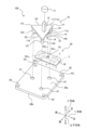
- FIG. 1 is an exploded perspective view of a pointing device according to an embodiment.
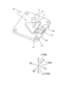
- FIG. 2 is a perspective view of the pointing device according to the embodiment.
- 3A is a top view of the main body and the strain sensor
- FIG 3B is a bottom view of the main body and the strain sensor.
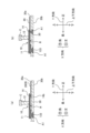
- Fig. 4(a) is a plan view of the pointing device according to the embodiment
- Fig. 4(b) is a cross-sectional view taken along line IVb-IVb in Fig. 4(a)
- Fig. 4(c) is a cross-sectional view taken along line IVc-IVc in Fig. 4(a).
- Fig. 5(a) is a cross-sectional view of a pointing device according to one modified example.
- Fig. 5(b) is a cross-sectional view of a pointing device according to another modified example.
- the cross-sectional position corresponds to the position along line IVc-IVc in Fig. 4(a).
- a pointing device 100 according to an embodiment of the present invention will be described with reference to FIGS.
- the pointing device 100 is a pointing stick assembly (PSA) equipped with a columnar operating unit 12.
- PSD pointing stick assembly
- the pointing device 100 mainly includes a main body 10, a strain sensor 20 that detects strain generated in the main body 10, and a support plate 30 that supports the main body 10.
- the direction in which the main body 10, the strain sensor 20, and the support plate 30 are arranged is the vertical direction.
- the side where the main body 10 is located with respect to the support plate 30 is the top, and the side where the support plate 30 is located with respect to the main body 10 is the bottom.
- one direction extending in a plane perpendicular to the vertical direction is the X direction
- a direction extending in a plane perpendicular to the vertical direction and perpendicular to the X direction is the Y direction.
- the direction of one side of the square support plate 30 is the X direction
- the direction of the other side perpendicular to the side is the Y direction.
- the positive side and negative side of the X direction and the Y direction are defined as shown in FIG. 1.
- the X direction and the Y direction are not limited to the example in FIG. 1.
- the X direction, the Y direction, and the vertical direction are examples of the first direction, the second direction, and the third direction of the present invention, respectively.
- the main body 10 is formed from resin, for example.
- the main body 10 can be formed by integral molding.
- the main body 10 includes a strain body 11, an operating part 12, three legs (i.e., a first leg 131, a second leg 132, and a third leg 133), and a protrusion 14.
- the flexure body 11 is a generally flat plate extending in a plane including the X and Y directions.
- the flexure body 11 is triangular in plan view (i.e., when viewed in the up-down direction) and has a first apex V1, a second apex V2, and a third apex V3, and a first side S1, a second side S2, and a third side S3.
- the first apex V1, the second apex V2, and the third apex V3 are rounded in plan view, but this is not limited to the above.
- the first apex V1 and the second apex V2 are aligned in the X direction.
- the first side S1 extends parallel to the X direction.
- a perpendicular line drawn from the third apex V3 to the first side S1 extends parallel to the Y direction.
- the second side S2 and the third side S3 are equal in length, and the first side S1 is longer than the second side S2 and the third side S3.
- the planar shape of the strain body 11 is an isosceles triangle.
- the center of the first side S1 of the flexure body 11 is provided with a protrusion 11p that is semicircular in plan view and protrudes from the first side S1 toward the positive side in the Y direction.
- the lower surface 11b of the flexure body 11 is provided with a recess R (see Figures 3(a) and 3(b)) that is rectangular in plan view. Note that it is not necessary to provide a recess R on the lower surface 11b.
- the operating unit 12 is the part operated by the user of the pointing device 100 (i.e., the part to which the user applies force).
- the operating unit 12 is provided on the upper surface 11a of the strain body 11.
- the operation unit 12 is a rectangular column extending in the vertical direction.
- the lower surface of the operation unit 12 is fixed to the upper surface 11a of the flexure body 11.
- the connection position of the operation unit 12 to the flexure body 11 is not particularly limited.
- the operation unit 12 is fixed to the positive side of the center of the flexure body 11 in the Y direction.
- the operation unit 12 may also be fixed to the position of the center of gravity of the flexure body 11 in a planar view.
- the operation unit 12 is arranged so that its four side surfaces face the positive X direction, negative X direction, positive Y direction, and negative Y direction, respectively.
- the orientation of the four side surfaces of the operation unit 12 is not limited to this.
- the four side surfaces of the operation unit 12 may face in a direction tilted by 45 degrees from the aforementioned direction in a planar view (i.e., in the XY plane).
- a cap C is attached to the upper end of the operating section 12.
- the cap C is the part that the operator of the pointing device 100 directly touches in order to operate the pointing device 100.
- the cap C may be made of rubber, for example.
- the first leg 131, the second leg 132, and the third leg 133 are support legs that are fixed to the support plate 30 and support the flexure body 11.
- the first leg 131 is provided on the first apex V1 of the flexure body 11
- the second leg 132 is provided on the second apex V2 of the flexure body 11
- the third leg 133 is provided on the third apex V3 of the flexure body 11.
- the first leg 131 and the second leg 132 are in the same position in the Y direction. That is, the first leg 131 and the second leg 132 are aligned in the X direction.
- the third leg 133 is located in the center position between the first leg 131 and the second leg 132 in the X direction. That is, the distance between the first leg 131 and the third leg 133 in the X direction is equal to the distance between the second leg 132 and the third leg 133 in the X direction.
- the third leg 133 is located on the negative side of the first leg 131 and the second leg 132 in the Y direction.
- the first leg 131, the second leg 132, and the third leg 133 are each a cylindrical leg extending downward from the lower surface 11b of the flexure body 11.
- the upper surfaces of the first leg 131 to the third leg 133 are formed integrally with the lower surface 11b of the flexure body 11. It is also possible to form the first leg 131 to the third leg 133 separately from the flexure body 11 and then later fix them to the flexure body 11 with an adhesive or the like.
- a protrusion 11p that protrudes in a plan view is formed on one side of the strain body 11.
- a cylindrical convex portion 14 extends downward from the lower surface 11b, which includes the lower surface of the protrusion 11p. The convex portion 14 is configured to adjust the amount of strain of the strain body 11 by abutting its lower end against the support plate 30.
- the upper surface of the convex portion 14 is formed integrally with the lower surface 11b.
- the convex portion 14 may be formed separately from the strain body 11 and then later fixed to the lower surface 11b, including the lower surface of the protrusion 11p, with an adhesive or the like.
- the convex portion 14 is located on the positive side of the first leg 131 and the second leg 132 in the Y direction.
- the protrusion 11p is located at the center between the first leg 131 and the second leg 132 in a plan view. Therefore, the convex portion 14 is also located at the center between the first leg 131 and the second leg 132, and the distance between the first leg 131 and the convex portion 14 in the X direction is equal to the distance between the second leg 132 and the convex portion 14 in the X direction.
- the convex portion 14 is in the same position as the third leg 133 in the X direction. In other words, the convex portion 14 and the third leg 133 are aligned in the Y direction.
- the vertical length of the protrusion 14 (i.e., the axial length of the cylinder) is shorter than the vertical lengths of the first leg 131, the second leg 132, and the third leg 133.
- the strain sensor 20 is attached to the strain body 11 with an adhesive or the like. In this embodiment having a recess R, the strain sensor 20 is attached to a bottom surface Rb of the recess R in the lower surface 11b. In an embodiment in which the lower surface 11b does not have a recess R, the strain sensor 20 is attached to the lower surface 11b.
- the strain sensor 20 includes a substrate B, four strain gauges (i.e., strain gauges SG X1 , SG X2 , SG Y1 , SG Y2 ) provided on the surface of the substrate B, and four tabs T provided on the surface of the substrate B.
- the substrate B is, for example, a flexible sheet formed of resin.
- the substrate B is substantially rectangular with the X direction as the short side direction and the Y direction as the long side direction.
- a through hole Th is provided in the substantially central portion of the substrate B in plan view, penetrating the substrate B.
- the through hole Th has a circular shape in plan view.
- An area of the substrate B located on the negative side in the Y direction from the through hole Th is attached to the bottom surface Rb of the recess R of the strain body 11 in a state where the recess R is fitted therein (FIGS. 2, 3(a), and 3(b)).
- the positioning of the strain body 11 and the substrate B can be easily performed. Therefore, the positioning of the strain body 11 and the strain gauges SG X1 , SG X2 , SG Y1 , and SG Y2 described later can also be easily performed.
- strain gauges SG X1 , SG X2 , SG Y1 , and SG Y2 are provided on the underside of the substrate B (i.e., the surface opposite to the upper surface of the substrate B attached opposite the flexure body 11) in a region located on the negative side of the Y direction relative to the through hole Th (i.e., the region attached to the flexure body 11).
- Each of the strain gauges SG X1 , SG X2 , SG Y1 , and SG Y2 includes a strain sensing portion (not shown) in which a linear resistor (not shown) is folded back in a zigzag pattern.
- the strain gauges SG X1 and SG X2 are arranged so that the grid direction of the strain sensing portion (the extension direction of the straight portion of the zigzag linear resistor, i.e., the strain sensing direction) is parallel to the X direction.
- the strain gauges SG Y1 and SG Y2 are arranged so that the grid direction of the strain sensing portion is parallel to the Y direction.
- the strain gauges SG X1 and SG X2 detect the strain of the strain body 11 in the X direction.
- the strain gauges SG Y1 and SG Y2 detect the strain of the strain body 11 in the Y direction. Therefore, the distortion detection directions of the pointing device 100 (directions in which the amount of operation by the operator is detected) are the X direction and the Y direction (and a direction obtained by combining these directional components).
- the four tabs T are provided in an area located on the lower surface of the base material B on the positive side in the Y direction from the through hole Th (i.e., an area not affixed to the strain gauge 11).
- Each of the four tabs T is rectangular in a plan view, and is connected to the strain gauges SGX1 , SGX2 , SGY1 , and SGY2 by wiring (not shown) formed on the base material B.
- the shape of the tabs T is not limited to the shape shown in the figure.
- the tabs T may be circular or elliptical.
- the operation unit 12 is located inside (e.g., approximately in the center of) the strain gauges SGX1 , SGX2 , SGY1, and SGY2 of the strain sensor 20 attached to the strain body 11.
- the first leg 131 is located on the positive side in the X direction of the strain gauges SGX1 , SGX2 , SGY1 , and SGY2
- the second leg 132 is located on the negative side in the X direction
- the convex portion 14 is located on the positive side in the Y direction
- the third leg 133 is located on the negative side in the Y direction.
- strain gauges SGX1 , SGX2 , SGY1 , and SGY2 are sandwiched between the first leg 131 and the second leg 132 in the X direction, and between the convex portion 14 and the third leg 133 in the Y direction.
- the convex portion 14 of the main body 10 is located within the through hole Th of the substrate B of the strain gauge 20.
- the fit between the convex portion 14 of the main body 10 and the through hole Th of the strain gauge 20 is used as a reference, making it possible to easily align the flexure body 11 with the strain gauges SG X1 , SG X2 , SG Y1 , and SG Y2 .
- the support plate 30 is a member that supports the main body 10 and is used to attach the pointing device 100 to the device to which it is to be attached (such as a personal computer or a game machine).
- the support plate 30 may be made of, for example, a metal (stainless steel is one example).
- the support plate 30 is a generally flat plate extending in a plane including the X-direction and the Y-direction. In this embodiment, the support plate 30 is square in plan view. However, the shape of the support plate 30 is not limited to this, and may be changed as appropriate depending on the specifications and shape of the object to be attached. For example, the support plate 30 can be in various shapes such as a rectangle, a circle, or an ellipse in plan view.
- each of the three openings A1 is an opening for fixing the main body 10.
- the three openings A1 are circular in plan view.
- Each of the three openings A1 is a stepped hole whose diameter near the lower surface 30b is larger than the diameter near the upper surface 30a (FIG. 4(b) and FIG. 4(c)).
- an opening A2 is provided at each of the four corners of the support plate 30.
- the number of openings A2 is not particularly limited.
- Each of the four openings A2 is an opening for mounting the support plate 30 (and thus the pointing device 100) to a device to which the support plate 30 (and thus the pointing device 100) is to be mounted (i.e., the device to be mounted).
- the four openings A2 are circular in plan view, but openings A1 and A2 may each have the shape of a screw hole to receive a screw portion.
- the main body 10 is fixed to the support plate 30.
- the first leg 131, the second leg 132, and the third leg 133 of the main body 10 are inserted into the opening A1 of the support plate 30 and fixed thereto by welding ( Figures 4(b) and 4(c)).
- the lower ends of the first leg 131, the second leg 132, and the third leg 133 are deformed by welding, and fill the inside of the opening A1 without protruding below the lower surface 30b of the support 30.
- the area of the lower surface 11b of the strain body 11 excluding the recessed portion R and the lower surface 14b of the protruding portion 14 abut against the upper surface 30a of the support plate 30.
- the entire lower surface 11b may be positioned with a gap between it and the upper surface 30a of the support plate 30.
- the lower surface 14b of the protruding portion 14 abuts against the upper surface 30a of the support plate 30.
- the pointing device 100 is fixed to the housing or substrate of the device to which the pointing device 100 is to be attached by screws or the like through the opening A2 of the support plate 30.
- the strain gauges SG X1 , SG X2 , SG Y1 , and SG Y2 are connected to the electrical configuration of the device to which the pointing device 100 is to be attached via the tabs T of the strain sensor 20.
- This forms, for example, a Wheatstone bridge including the strain gauges SG X1 , SG X2 and a resistor external to the pointing device 100, and a Wheatstone bridge including the strain gauges SG Y1 , SG Y2 and a resistor external to the pointing device 100.
- the pointing device 100 detects the magnitude of the strain generated in the strain body 11 by the strain sensor 20, thereby obtaining the operation amount input by the operator.
- the operation amount in the X direction is obtained using a Wheatstone bridge including strain gauges SG X1 and SG X2
- the operation amount in the Y direction is obtained using a Wheatstone bridge including strain gauges SG Y1 and SG Y2 .
- the pointing device 100 inputs the obtained operation amount to the device on which the pointing device 100 is mounted (i.e., the device to be attached).
- the pointing device 100 may calculate the operation amount for a direction (i.e., any direction of 360 degrees on the XY plane) obtained by combining the components in the X direction and the Y direction, and input the calculated operation amount to the device to be attached.
- the pointing device 100 of this embodiment supports the flexure body 11, which is triangular in plan view, by a first leg 131, a second leg 132, and a third leg 133 provided on the three vertices V1, V2, and V3 of the flexure body 11. Therefore, the area of the flexure body 11 located outside the outline obtained by connecting the first leg 131, the second leg 132, and the third leg 133 is small, making it compact and space-efficient.
- the compactness of the flexure body 11 is particularly advantageous when attaching the pointing device 100 to various devices.
- notebook computers and game consoles to which the pointing device 100 is to be attached are required to be compact, and the space available inside these devices for installing the pointing device 100 is limited.
- by making the flexure body 11 of the pointing device 100 compact and space-efficient in shape it becomes possible to install the pointing device 100 compactly and efficiently inside the device to which the pointing device 100 is to be attached.
- a first leg 131 and a second leg 132 are provided on both sides in the X direction of the strain gauges SGX1 , SGX2 , SGY1 , and SGY2 .
- a third leg 133 and a protrusion 14 are provided on both sides in the Y direction of the strain gauges SGX1 , SGX2 , SGY1 , and SGY2 .
- the state of strain generated in the strain body 11 can be made uniform in the X direction and the Y direction. This can improve the accuracy of strain detection using the strain sensor 20.
- the convex portion 14 is disposed on the positive side in the Y direction relative to the first leg 131 and the second leg 132.
- the convex portion 14 of the pointing device 100 of this embodiment is disposed on the opposite side in the Y direction to the side on which the strain gauges SG X1 , SG X2 , SG Y1 , and SG Y2 are disposed, across a reference line connecting the first leg 131 and the second leg 132.
- the convex portion 14 is not fixed to the support plate 30. Therefore, there is no need to weld the convex portion 14 to the support plate 30, and the main body 10 can be fixed to the support plate 30 with less effort.
- the shape of the flexure body 11 in a plan view is an isosceles triangle, but this is not limited to this.
- the shape of the flexure body 11 in a plan view may be any triangle, such as an equilateral triangle or a right-angled triangle.
- the pointing device 100 may be configured such that the strain body 11 is an isosceles triangle, the direction of its base coincides with either the X direction or the Y direction (i.e., one of the two strain detection directions), and the direction perpendicular to the base coincides with the other of the X direction or the Y direction (i.e., the other of the two strain detection directions).
- This makes it possible to homogenize the strain pattern generated in the strain body 11 in the X direction and the Y direction, and further improves the accuracy of strain detection using the strain sensor 20.
- the pointing device 100 may be configured such that the flexure body 11 is an equilateral triangle, with one side aligned with either the X or Y direction (i.e., one of the two strain detection directions), and the direction perpendicular to the side aligned with the other of the X or Y directions (i.e., the other of the two strain detection directions). This makes it possible to homogenize the strain occurring in the flexure body 11 in the X and Y directions, thereby further improving the accuracy of strain detection using the strain sensor 20.
- the operating unit 12 is a rectangular prism, and the first leg 131, the second leg 132, the third leg 133, and the protrusion 14 are cylindrical.
- the operating unit 12 may be of any shape, such as a cylindrical column, a cylinder, a triangular prism, etc.
- the first leg 131, the second leg 132, the third leg 133, and the protrusion 14 may be of any shape, such as a cylinder, a rectangular prism, a triangular prism, etc.
- a through hole Th is provided in the base material B of the strain sensor 20, and when the main body 10, the strain sensor 20, and the support plate 30 are combined together, the convex portion 14 of the main body 10 passes through the through hole Th of the base material B and abuts against the support plate 30.
- the through hole Th of the base material B may be omitted, and the base material B may be sandwiched between the lower surface 14b of the convex portion 14 and the upper surface 30a of the support plate 30, as shown in FIG. 5(a).
- the convex portion 14 may be welded and fixed to the support plate 30 in the same manner as the first leg portion 131 to the third leg portion 133. In this case, the vertical dimension of the convex portion 14 is increased, and an opening A1 is provided at a position on the support plate 30 corresponding to the convex portion 14.
- the protrusion 14 of the main body 10 is located at the center position between the first leg 131 and the second leg 132 in the X direction, but this is not limited to this.
- the protrusion 14 can be located at any position in the X direction.
- the convex portion 14 of the main body 10 is located on the positive side in the Y direction relative to the first leg 131 and the second leg 132, but this is not limited to this.
- the convex portion 14 may be located in the same position as the first leg 131 and the second leg 132 in the Y direction, or may be located on the negative side of the first leg 131 and the second leg 132 in the Y direction.
- the main body 10 may be configured such that the center position between the first leg 131 and the second leg 132 in the X direction coincides with the center position between the strain gauge SG X1 and the strain gauge SG X2 . This allows the strain occurring in the X direction of the strain body 11 to be detected with higher accuracy. Also, in the pointing device 100 of the above embodiment, the main body 10 may be provided such that the center position between the convex portion 14 and the third leg 133 in the Y direction coincides with the center position between the strain gauge SG Y1 and the strain gauge SG Y2 . This allows the strain occurring in the Y direction of the strain body 11 to be detected with higher accuracy.
- the convex portion 14 may be omitted.
- the thickness (vertical dimension) of the strain body 11 may be changed in a plane including the X direction and the Y direction, as necessary.
- the strain sensor 20 is used in which the four strain gauges SGX1 , SGX2 , SGY1 , and SGY2 are integrally provided on the substrate B, but this is not limited to this.
- the strain gauges SGX1 , SGX2 , SGY1 , and SGY2 may be four strain gauges that are separate from one another. Furthermore, it is sufficient that at least one strain gauge that detects strain in the X direction and at least one strain gauge that detects strain in the Y direction are attached to the strain generating body 11.
- the strain gauge 20 is drawn out to the outside of the flexure body 11 between the first leg 131 and the second leg 132 of the main body 10, but this is not limited to the above.
- the strain gauge 20 may be drawn out to the outside of the flexure body 11 between the second leg 132 and the third leg 133 of the main body 10, or may be drawn out to the outside of the flexure body 11 between the third leg 133 and the first leg 131 of the main body 10.
- the strain gauge 20 itself may be sized to fit between the flexure body 11 and the support plate 30, and the wiring drawn out from the strain gauge 20 may be drawn out to the outside of the flexure body 11 and connected to the electrical configuration (circuit, etc.) of the device to which the pointing device 100 is attached.
- the support plate 30 may be omitted.
- the first leg 131 to the third leg 133 of the main body 10 are fixed to a part of the device to which the pointing device 100 is to be attached (for example, a board built into the device to which the pointing device 100 is to be attached).
- the part of the device to which the pointing device 100 is to be attached corresponds to the "support" of the present invention.
- the present invention is not limited to the above-described embodiment, and other forms that are conceivable within the scope of the technical concept of the present invention are also included within the scope of the present invention.
Landscapes
- Engineering & Computer Science (AREA)
- General Engineering & Computer Science (AREA)
- Theoretical Computer Science (AREA)
- Human Computer Interaction (AREA)
- Physics & Mathematics (AREA)
- General Physics & Mathematics (AREA)
- Position Input By Displaying (AREA)
- Switches With Compound Operations (AREA)
Priority Applications (2)
| Application Number | Priority Date | Filing Date | Title |
|---|---|---|---|
| EP23894169.4A EP4625119A1 (en) | 2022-11-22 | 2023-07-06 | Pointing device |
| CN202380080604.9A CN120225979A (zh) | 2022-11-22 | 2023-07-06 | 定点设备 |
Applications Claiming Priority (2)
| Application Number | Priority Date | Filing Date | Title |
|---|---|---|---|
| JP2022186564A JP2024075251A (ja) | 2022-11-22 | 2022-11-22 | ポインティングデバイス |
| JP2022-186564 | 2022-11-22 |
Publications (1)
| Publication Number | Publication Date |
|---|---|
| WO2024111153A1 true WO2024111153A1 (ja) | 2024-05-30 |
Family
ID=91195996
Family Applications (1)
| Application Number | Title | Priority Date | Filing Date |
|---|---|---|---|
| PCT/JP2023/025081 Ceased WO2024111153A1 (ja) | 2022-11-22 | 2023-07-06 | ポインティングデバイス |
Country Status (4)
| Country | Link |
|---|---|
| EP (1) | EP4625119A1 (enExample) |
| JP (1) | JP2024075251A (enExample) |
| CN (1) | CN120225979A (enExample) |
| WO (1) | WO2024111153A1 (enExample) |
Citations (3)
| Publication number | Priority date | Publication date | Assignee | Title |
|---|---|---|---|---|
| US20010017187A1 (en) * | 2000-02-21 | 2001-08-30 | Darfon Electronics Corp. | Method of manufacturing a pointing stick |
| JP2004171200A (ja) * | 2002-11-19 | 2004-06-17 | Alps Electric Co Ltd | 座標入力装置 |
| JP2011175390A (ja) * | 2010-02-23 | 2011-09-08 | Minebea Co Ltd | ポインティングスティック |
-
2022
- 2022-11-22 JP JP2022186564A patent/JP2024075251A/ja active Pending
-
2023
- 2023-07-06 CN CN202380080604.9A patent/CN120225979A/zh active Pending
- 2023-07-06 WO PCT/JP2023/025081 patent/WO2024111153A1/ja not_active Ceased
- 2023-07-06 EP EP23894169.4A patent/EP4625119A1/en active Pending
Patent Citations (4)
| Publication number | Priority date | Publication date | Assignee | Title |
|---|---|---|---|---|
| US20010017187A1 (en) * | 2000-02-21 | 2001-08-30 | Darfon Electronics Corp. | Method of manufacturing a pointing stick |
| JP2004171200A (ja) * | 2002-11-19 | 2004-06-17 | Alps Electric Co Ltd | 座標入力装置 |
| JP2011175390A (ja) * | 2010-02-23 | 2011-09-08 | Minebea Co Ltd | ポインティングスティック |
| JP5285001B2 (ja) | 2010-02-23 | 2013-09-11 | ミネベア株式会社 | ポインティングスティック |
Non-Patent Citations (1)
| Title |
|---|
| See also references of EP4625119A1 |
Also Published As
| Publication number | Publication date |
|---|---|
| EP4625119A1 (en) | 2025-10-01 |
| JP2024075251A (ja) | 2024-06-03 |
| CN120225979A (zh) | 2025-06-27 |
Similar Documents
| Publication | Publication Date | Title |
|---|---|---|
| JP5889661B2 (ja) | 入力装置 | |
| US6556186B2 (en) | Keyboard input device with pointing device for controlling cursor position on graphic display and the like | |
| US8780543B2 (en) | Integrated feature for friction-less movement of force sensitive touch screen | |
| CN217443844U (zh) | 触控板、压力触控装置和电子设备 | |
| WO2002014807A1 (en) | Weighing scale | |
| JP2019101562A (ja) | タッチパッドモジュール | |
| JP2013182424A (ja) | 入力装置 | |
| WO2024111153A1 (ja) | ポインティングデバイス | |
| CN115202492A (zh) | 触控板装置及具有它的电子设备 | |
| EP4625120A1 (en) | Pointing device | |
| CN116486767A (zh) | 键盘单元 | |
| JP7596628B2 (ja) | 多方向入力装置 | |
| CN211529136U (zh) | 一种触控装置 | |
| JP2024124894A (ja) | 多方向入力装置 | |
| JP2011249637A (ja) | 回路基板アッセンブリ | |
| JP4301781B2 (ja) | 操作装置 | |
| CN222801133U (zh) | 弹性触控板装置及具有它的电子设备 | |
| JP7601695B2 (ja) | タッチパネル付き表示装置 | |
| CN218068831U (zh) | 压力触控板和电子设备 | |
| CN222896413U (zh) | 触控板模组及电子设备 | |
| JP7340089B2 (ja) | 移動機構、及び、入力装置 | |
| TW202537679A (zh) | 多方向輸入裝置 | |
| JP4773683B2 (ja) | 座標入力装置 | |
| CN120821385A (zh) | 触控板按压模块 | |
| CN118715586A (zh) | 多方向输入装置 |
Legal Events
| Date | Code | Title | Description |
|---|---|---|---|
| 121 | Ep: the epo has been informed by wipo that ep was designated in this application |
Ref document number: 23894169 Country of ref document: EP Kind code of ref document: A1 |
|
| WWE | Wipo information: entry into national phase |
Ref document number: 202380080604.9 Country of ref document: CN |
|
| WWE | Wipo information: entry into national phase |
Ref document number: 2023894169 Country of ref document: EP |
|
| NENP | Non-entry into the national phase |
Ref country code: DE |
|
| WWP | Wipo information: published in national office |
Ref document number: 202380080604.9 Country of ref document: CN |
|
| ENP | Entry into the national phase |
Ref document number: 2023894169 Country of ref document: EP Effective date: 20250623 |
|
| WWP | Wipo information: published in national office |
Ref document number: 2023894169 Country of ref document: EP |