WO2024111117A1 - 電気自動車充電システム、電力管理装置及び電気自動車充電方法 - Google Patents
電気自動車充電システム、電力管理装置及び電気自動車充電方法 Download PDFInfo
- Publication number
- WO2024111117A1 WO2024111117A1 PCT/JP2022/043558 JP2022043558W WO2024111117A1 WO 2024111117 A1 WO2024111117 A1 WO 2024111117A1 JP 2022043558 W JP2022043558 W JP 2022043558W WO 2024111117 A1 WO2024111117 A1 WO 2024111117A1
- Authority
- WO
- WIPO (PCT)
- Prior art keywords
- power
- electric vehicle
- substation
- train
- private line
- Prior art date
- Legal status (The legal status is an assumption and is not a legal conclusion. Google has not performed a legal analysis and makes no representation as to the accuracy of the status listed.)
- Ceased
Links
Images




Classifications
-
- B—PERFORMING OPERATIONS; TRANSPORTING
- B60—VEHICLES IN GENERAL
- B60L—PROPULSION OF ELECTRICALLY-PROPELLED VEHICLES; SUPPLYING ELECTRIC POWER FOR AUXILIARY EQUIPMENT OF ELECTRICALLY-PROPELLED VEHICLES; ELECTRODYNAMIC BRAKE SYSTEMS FOR VEHICLES IN GENERAL; MAGNETIC SUSPENSION OR LEVITATION FOR VEHICLES; MONITORING OPERATING VARIABLES OF ELECTRICALLY-PROPELLED VEHICLES; ELECTRIC SAFETY DEVICES FOR ELECTRICALLY-PROPELLED VEHICLES
- B60L53/00—Methods of charging batteries, specially adapted for electric vehicles; Charging stations or on-board charging equipment therefor; Exchange of energy storage elements in electric vehicles
-
- B—PERFORMING OPERATIONS; TRANSPORTING
- B60—VEHICLES IN GENERAL
- B60M—POWER SUPPLY LINES, AND DEVICES ALONG RAILS, FOR ELECTRICALLY- PROPELLED VEHICLES
- B60M3/00—Feeding power to supply lines in contact with collector on vehicles; Arrangements for consuming regenerative power
- B60M3/06—Arrangements for consuming regenerative power
-
- H—ELECTRICITY
- H02—GENERATION; CONVERSION OR DISTRIBUTION OF ELECTRIC POWER
- H02J—ELECTRIC POWER NETWORKS; CIRCUIT ARRANGEMENTS OR SYSTEMS FOR SUPPLYING OR DISTRIBUTING ELECTRIC POWER; SYSTEMS FOR STORING ELECTRIC ENERGY
- H02J3/00—Circuit arrangements for AC mains or AC distribution networks
- H02J3/38—Arrangements for feeding a single network from two or more generators or sources in parallel; Arrangements for feeding already energised networks from additional generators or sources in parallel
-
- H—ELECTRICITY
- H02—GENERATION; CONVERSION OR DISTRIBUTION OF ELECTRIC POWER
- H02J—ELECTRIC POWER NETWORKS; CIRCUIT ARRANGEMENTS OR SYSTEMS FOR SUPPLYING OR DISTRIBUTING ELECTRIC POWER; SYSTEMS FOR STORING ELECTRIC ENERGY
- H02J7/00—Circuit arrangements for charging or discharging batteries or for supplying loads from batteries
Definitions
- This disclosure relates to an electric vehicle charging system that charges the battery of an electric vehicle, a power management device used therein, and an electric vehicle charging method.
- Electric vehicles also known as EVs (Electric Vehicles)
- EVs Electric Vehicles
- an electric vehicle charging device is connected to a railway feeder line, and regenerative power generated when the railway train brakes is collected and stored in a power storage device, which is then used to charge the electric vehicle.
- regenerative power that is normally wasted is used to charge the electric vehicle, resulting in energy savings.
- the capacity of substation equipment related to railway power feeding equipment is designed to match the peak power required by trains. For this reason, when connecting electric vehicle charging equipment to railway feeder lines, the capacity of the substation equipment must be significantly increased to add electric vehicle charging equipment with high peak power, resulting in high costs.
- the present disclosure has been made in consideration of the above, and aims to provide an electric vehicle charging system that increases the number of electric vehicles that can be charged without increasing the capacity of the substation equipment.
- the electric vehicle charging system disclosed herein comprises a charging station equipped with a charger capable of charging an electric vehicle using power supplied from a private line, a substation that supplies power to the private line and a feeder, a power converter installed between the feeder and the private line and that steps down the power supplied from the feeder to the private line, and a power management device that manages the power supplied to the charging station by controlling the substation and the power converter.
- the power management device predicts the power used by a train connected to the feeder when powering, the regenerative power generated when the train is braking, and the available capacity of the substation for each time period, and controls the substation and the power converter based on the predictions so that the power supplied to the substation does not exceed a preset rated capacity.
- the present disclosure has the effect of providing an electric vehicle charging system that increases the number of electric vehicles that can be charged without increasing the capacity of the substation equipment.
- FIG. 1 is a diagram showing a configuration of an electric vehicle charging system according to a first embodiment
- FIG. 2 is a diagram showing the operation of a power management device and an electric vehicle operation management device in the electric vehicle charging system according to the first embodiment
- FIG. 1 is a diagram showing a configuration of a power management device of an electric vehicle charging system according to a first embodiment.
- FIG. 1 is a diagram showing a configuration of an electric vehicle operation management device according to a first embodiment.
- FIG. 1 is a diagram showing an example of electric power generated in an electric vehicle charging system according to a first embodiment; A flowchart showing the operation flow of the power management device and the electric vehicle operation management device of the electric vehicle charging system according to the first embodiment.
- FIG. 1 is a diagram showing a configuration of an electric vehicle charging system according to a first embodiment
- FIG. 2 is a diagram showing the operation of a power management device and an electric vehicle operation management device in the electric vehicle charging system according to the first embodiment
- FIG. 1 is a diagram showing a configuration of
- FIG. 13 shows a configuration of an electric vehicle charging system according to a second embodiment.
- FIG. 13 is a diagram showing an example of electric power generated in an electric vehicle charging system according to a second embodiment.
- FIG. 13 is a diagram showing the configuration of an electric vehicle charging system according to a third embodiment.
- FIG. 13 is a diagram showing an example of electric power generated in an electric vehicle charging system according to a third embodiment.
- FIG. 1 is a diagram showing an example of a hardware configuration of a power management device of an electric vehicle charging system according to any one of the first to third embodiments.
- Fig. 1 is a diagram showing the configuration of an electric vehicle charging system according to embodiment 1.
- Fig. 2 is a diagram showing a schematic diagram of the operation of a power management device and an electric vehicle operation management device in the electric vehicle charging system according to embodiment 1.
- An electric vehicle charging system 300 according to embodiment 1 includes a charging station 6 for charging an electric vehicle 600, a private line 9 laid by an installer of the charging station 6, a main substation equipment 1 connected to a power grid, and a feeding substation equipment 2 and a private line substation equipment 3 connected to the main substation equipment 1.
- the electric vehicle charging system 300 also includes a solar power generation facility 7 connected to the private line 9 via a power converter 701, a power converter 8 installed between the feeder line 5 and the private line 9, a power management device 50 that manages the power supplied to the charging station 6, and an electric vehicle operation management device 60 that manages the operation of the electric vehicle 600.
- the main substation 1, the feeding substation 2, and the private line substation 3 are substation equipment that supplies power to the private line 9 and the feeder 5.
- the main substation 1 steps down the AC power P1 supplied from the power grid and outputs it.
- the feeding substation 2 steps down and converts the AC power P2 supplied from the main substation 1 into DC, and supplies it to the feeder 5 for supplying power to the train 4.
- the private line substation 3 steps down the AC power P3 supplied from the main substation 1 and supplies it to the private line 9.
- the current flowing through the private line 9 is AC.
- the power P1 supplied to the main substation 1 is the sum of the power P2 supplied to the feeding substation 2 and the power P3 supplied to the private line substation 3.
- the charging station 6 includes a charger 601 that charges the electric vehicle 600, a storage battery 602 that stores power, a power converter 604 that steps down the power that charges the storage battery 602 and steps up the power discharged by the storage battery 602, and a power converter 603 that converts the power supplied from the private line 9 to DC and steps down the voltage.
- the power management device 50 communicates with the charger 601, power converter 603, and power converter 604, and charges the electric vehicle 600, charges and discharges the storage battery 602, and supplies power from the private line 9 to the charging station 6.
- the electric vehicle operation management device 60 communicates with each of the multiple electric vehicles 600, and instructs them to operate based on a preset operation schedule.
- the power feeding substation 2 includes a transformer 201 and a rectifier 202.
- the power P2 supplied to the power feeding substation 2 is stepped down by the transformer 201, and is then converted to DC power by the rectifier 202 and supplied to the feeder line 5 as DC power.
- the train 4 exchanges DC power with the feeder line 5.
- the electric power supplied from the feeder 5 to the train 4 is defined as positive electric power
- the electric power supplied from the train 4 to the feeder 5 is defined as negative electric power.
- the train 4 receives electric power P4 from the feeder 5, so the electric power P4 is positive electric power.
- the train 4 brakes regenerative electric power obtained by converting kinetic energy into electrical energy is supplied from the train 4 to the feeder 5, so the electric power P4 is negative electric power.
- the power converter 8 converts the power supplied from the feeder 5 to the private line 9 into AC power and boosts its voltage.
- power P5 is supplied from the feeder 5 to the private line 9 via the power converter 8.
- the solar power generation facility 7 generates solar power.
- the power converter 701 converts the power obtained by solar power generation in the solar power generation facility 7 into AC power and boosts its voltage, and supplies the solar-generated power P7 to the private line 9.
- the charging station 6 is supplied with power P6 from the private line 9 via a power converter 603.
- the power P6 supplied to the charging station 6 is the sum of the power P3 stepped down in the private line substation 3, the solar power generation power P7, and the regenerative power P5.
- FIG. 3 is a diagram showing the configuration of a power management device of an electric vehicle charging system according to the first embodiment.
- the power management device 50 includes a control unit 51 that controls the charger 601, the storage battery 602, the power converter 603, the power converter 604, the power converter 8, the power supply substation 2, and the private line substation 3, and a processing unit 52 that creates a maximum charging power table that indicates the maximum power that can be supplied to the charger 601 by the charging and discharging control of the storage battery 602 for each time period, and a charging fee table that indicates the charging fee for the electric vehicle 600 for each time period.
- the processing unit 52 includes a photovoltaic power generation amount prediction unit 521 that predicts the amount of power of the photovoltaic power generation power P7, a regenerative power amount prediction unit 522 that predicts the amount of power of the regenerative power, a substation equipment available capacity prediction unit 523 that predicts the available capacity of the main substation equipment 1, and a table creation unit 524 that creates the maximum charging power table and the charging fee table.
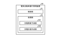
- FIG. 4 is a diagram showing the configuration of an electric vehicle operation management device according to embodiment 1.
- the electric vehicle operation management device 60 includes a control unit 61 that dispatches electric vehicles 600, and a processing unit 62 that creates a charging plan for the electric vehicles 600.
- the processing unit 62 includes a charging demand prediction unit 621 that predicts the charging demand for the electric vehicles 600, and a charging plan creation unit 622 that creates a charging plan for the electric vehicles 600.
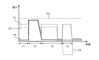
- FIG. 5 is a diagram showing an example of power generated in the electric vehicle charging system according to the first embodiment.
- the vertical axis indicates power
- the horizontal axis indicates time.
- T1 the train 4 is stopped, and the power P2 supplied to the feeding substation 2 is small.
- time period T2 the train 4 is powered, and the power P2 supplied to the feeding substation 2 is large.
- time period T3 the train 4 is coasting, and the power P2 supplied to the feeding substation 2 is small.
- the train 4 is braking, and regenerative power is supplied from the train 4 to the feeder 5, so the power P4 exchanged between the train 4 and the feeder 5 is negative.
- the power management device 50 controls the charger 601, the storage battery 602, the power converter 603, the power converter 604, the power converter 8, and the power converter 701 to supply power P3 to the private line substation 3 without restrictions during time periods T1 and T3 when the power P2 supplied to the power feeding substation 2 is small, and suppresses the power P3 supplied to the private line substation 3 during time period T2 when the power P2 received by the power feeding substation 2 is large.
- the power P2 supplied to the power feeding substation 2 peaks in time period T2 when the train 4 is powered.
- the power management device 50 suppresses the power P3 supplied to the private line substation 3, so that the peak of the power P3 occurs during time period T1 or T3 when the power P2 supplied to the power feeding substation 2 is low.
- FIG. 6 is a flowchart showing the flow of the operation of the power management device and the electric vehicle operation management device of the electric vehicle charging system according to the first embodiment.
- the solar power generation amount prediction unit 521 predicts the amount of power generated by the solar power generation facility 7 based on a weather forecast.
- the regenerative power amount prediction unit 522 predicts the amount of power used by the train 4, the amount of regenerative power generated, and the time period during which the regenerative power will be generated based on the railway operation information.
- the railway operation information includes predicted data on the operation schedule and number of passengers of the train 4, etc.
- the regenerative power amount prediction unit 522 predicts the amount of power used by the train 4 and the time period during which the train 4 will use power by estimating the time period during which the train 4 will brake based on the railway operation information. In addition, the regenerative power amount prediction unit 522 predicts the amount of regenerative power generated and the time period during which the regenerative power will be generated by estimating the time period during which the train 4 will brake based on the railway operation information.
- the substation free capacity prediction unit 523 also predicts the free capacity of the main substation 1.
- the substation free capacity prediction unit 523 estimates the time period during which the train 4 will be powered based on train operation information, and predicts the power P2 supplied to the feeding substation 2, the power P3 supplied to the private line substation 3, and the power P1 supplied to the main substation 1, which is the sum of the power P2 and the power P3.
- the substation free capacity prediction unit 523 estimates the free capacity relative to the rated capacity Pn1 of the main substation 1 based on the power P1 supplied to the main substation 1, the power P2 supplied to the feeding substation 2, and the power P3 supplied to the private line substation 3.
- step S3 the table creation unit 524 creates a maximum charging power table and a charging fee table.
- the power P3 that can be supplied by the private line substation 3 is restricted for each time period depending on the power P2 supplied to the feeding substation 2. Therefore, the maximum power that can be supplied to the charging station 6 varies depending on the power P2 supplied to the feeding substation 2, the photovoltaic power P7 supplied from the photovoltaic power generation equipment 7, and the power P5 due to regenerative power supplied from the train 4.
- the table creation unit 524 creates a maximum charging power table as a table for each time period for the maximum power that can be supplied to the charger 601 by the charge and discharge control of the storage battery 602 installed in the charging station 6, based on the power P2 supplied to the feeding substation 2, the photovoltaic power P7 supplied from the photovoltaic power generation equipment 7, and the power P5 due to regenerative power supplied from the train 4.
- the charging fee table is created based on the maximum charging power table, the predicted value of the photovoltaic power generation power P7, and the predicted value of the regenerative power.
- the charging fee is set to a low value in the time period when the photovoltaic power generation power P7 and the regenerative power are generated in large amounts.
- the available capacity of the main substation 1 is small and the maximum charging power is small.
- the charging fee is set to a high value in order to avoid a concentration of charging demand.
- the table creation unit 524 optimizes the charging plan for the electric vehicle 600 by setting the charging fee to a variable fee that differs for each time period based on the maximum charging power based on the available capacity of the main substation 1, the photovoltaic power generation power P7, and the predicted value of the regenerative power.
- step S4 the control unit 51 transmits the maximum charging power table and the charging fee table created by the table creation unit 524 to the electric vehicle operation management device 60.
- the charging demand prediction unit 621 predicts the charging demand of the electric vehicle 600 based on the electric vehicle operation information.
- the electric vehicle operation information includes the bus schedule and predicted data on the number of bus passengers.
- the electric vehicle operation information includes predicted data on the number of taxi passengers and the transportation distance.
- the electric vehicle operation information includes predicted data on traffic information indicating the degree of road congestion.
- step S12 the control unit 61 of the electric vehicle operation management device 60 receives the maximum charging power table and the charging fee table transmitted from the power management device 50.
- step S13 the charging plan creation unit 622 creates a charging plan for the electric vehicle 600 whose operation it manages, based on the maximum charging power table and the charging fee table. For example, the charging plan creation unit 622 creates a charging plan so that charging of the electric vehicle 600 is given priority during time periods when the charging fee for the electric vehicle 600 is set low.
- step S14 the control unit 61 transmits the charging plan created by the charging plan creation unit 622 to the power management device 50.
- step S5 the control unit 51 of the power management device 50 receives the charging plan transmitted from the electric vehicle operation management device 60.
- the power management device 50 displays the charging plan received from the electric vehicle operation management device 60 on a display unit (not shown) or makes it public via the Internet, so that users of electric vehicles 600 whose operation is not managed by the electric vehicle operation management device 60 can know the degree of congestion at the charging station 6 in advance.
- the above operations are repeatedly performed at preset time intervals even after the opening of business.
- the system is operated while making sequential corrections in response to at least one of the following: changes in the weather forecast, delays in train or bus schedules, and updates to electric vehicle operation information.
- the electric vehicle charging system 300 according to embodiment 1 can increase the number of electric vehicles 600 that can be charged without increasing the capacity of the main substation equipment 1.
- the electric vehicle charging system 300 predicts the power usage of the train 4 connected to the feeder line 5 when it is powered, the regenerative power generated when the train 4 is braking, and the available capacity of the main substation 1 for each time period, and based on the predictions, controls the feeding substation 2 and the power converter 8 so that the power supplied to the main substation 1 does not exceed a preset rated capacity. This makes it possible to increase the number of electric vehicles 600 that can be charged without performing equipment updates that increase the rated capacity of the main substation 1.
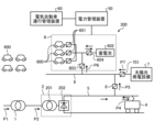
- Embodiment 2. 7 is a diagram showing the configuration of an electric vehicle charging system according to embodiment 2. Only the parts that differ from electric vehicle charging system 300 according to embodiment 1 will be described, and a description of the common parts will be omitted.
- the current flowing through the private line 9 is direct current.
- the power feeding substation 2 steps down and converts the power P2 supplied from the main substation 1 to direct current, and supplies the direct current power to the feeder line 5.
- a power converter 8 is installed between the feeder line 5 and the private line 9. Power is supplied to the private line 9 from the power feeding substation 2 via the power converter 8.
- the power converter 603 steps down the power supplied from the private line 9.
- the power converter 701 boosts the power obtained by solar power generation in the solar power generation facility 7, and supplies the solar power generation power P7 to the private line 9.
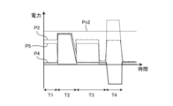
- FIG. 8 is a diagram showing an example of power generated in an electric vehicle charging system according to embodiment 2.
- the vertical axis represents power, and the horizontal axis represents time.
- Power P2 is power supplied to the feeding substation 2 from the main substation 1.
- Power P4 is power exchanged between the train 4 and the feeder 5.
- Power P5 is power supplied from the feeder 5 to the private line 9 via the power converter 8.
- the power supplied from the feeder 5 to the train 4 is defined as positive power, and the power supplied from the train 4 to the feeder 5 is defined as negative power.
- Time period T1 is a time period when train 4 is stopped, and the positive power P4 supplied to train 4 from feeder 5 is small.
- Time period T2 is a time period when train 4 is powered, and the positive power P4 supplied to train 4 from feeder 5 is large.
- Time period T3 is a time period when train 4 is coasting, and the positive power P4 supplied to train 4 from feeder 5 is small.
- Time period T4 is a time period when train 4 is braking, and negative power is supplied from train 4 to feeder 5.
- the power management device 50 controls the charger 601, the storage battery 602, the power converter 603, the power converter 604, and the power converter 8 so that the power converter 8 supplies power P5 from the feeder 5 to the private line 9 during time periods T1 and T3 when the positive power supplied from the feeder 5 to the train 4 is small, and during time period T4 when the train 4 supplies negative power to the feeder 5, and controls to suppress the power P5 supplied from the feeder 5 to the private line 9 during time period T2 when the positive power supplied from the feeder 5 to the train 4 is large.
- the power management device 50 suppresses the power P5 supplied from the feeder 5 to the private line 9, so that the power P2 supplied from the main substation 1 to the feeding substation 2 is kept at or below the rated capacity Pn2, while a large amount of power P6 exceeding the rated capacity Pn2 can be supplied to the charging station 6 via the private line 9. This makes it possible to increase the number of electric vehicles 600 that can be charged without performing equipment upgrades that increase the rated capacity of the main substation 1 and the feeding substation 2.
- the flow of operation of the electric vehicle charging system 300 according to the second embodiment is the same as the flow of operation of the electric vehicle charging system 300 according to the first embodiment shown in FIG. 6, but in step S2, the substation free capacity prediction unit 523 calculates the free capacity of the feeding substation 2, not the free capacity of the main substation 1.
- the table creation unit 524 creates a charging fee table by setting a high charging fee in a time period when the free capacity of the feeding substation 2 is small and the maximum charging power is small because the train 4 is powered and the power P2 supplied to the feeding substation 2 is large, in order to avoid charging demand being concentrated in that time period.
- the charging fee is set to a variable fee that differs for each time period based on the maximum charging power based on the free capacity of the feeding substation 2, the solar power generation power P7, and the predicted value of the regenerative power, thereby promoting optimization of the charging plan for the electric vehicle 600.
- the electric vehicle charging system 300 predicts the power usage of the train 4 connected to the feeder line 5 when it is powered, the regenerative power generated when the train 4 is braking, and the available capacity of the feeding substation 2 for each time period, and based on the predictions, controls the power converter 8 so that the power supplied to the feeding substation 2 does not exceed a preset rated capacity. This makes it possible to increase the number of electric vehicles 600 that can be charged without performing equipment updates that increase the rated capacity of the feeding substation 2.
- Embodiment 3. 9 is a diagram showing the configuration of an electric vehicle charging system according to embodiment 3. Only the parts that differ from electric vehicle charging system 300 according to embodiment 2 will be described, and a description of the common parts will be omitted.
- the current flowing through the private line 9 is direct current.
- the power feeding substation 2 includes a power converter 203 that steps down the direct current power output from the rectifier 202.
- the power feeding substation 2 supplies the private line 9 with direct current power stepped down by the transformer 201, and supplies the feeder line 5 with direct current power stepped down by the power converter 203.
- the regenerative power generated during braking of the train 4 is collected by the feeder line 5, the regenerative power is boosted by the power converter 8, and power P5 is supplied from the feeder line 5 to the private line 9.
- the solar power generation facility 7 is installed in the charging station 6.
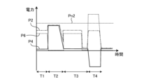
- FIG. 10 is a diagram showing an example of power generated in an electric vehicle charging system according to embodiment 3.
- the vertical axis represents power, and the horizontal axis represents time.
- Power P2 is power supplied to the feeding substation 2.
- Power P4 is power exchanged between the train 4 and the feeder 5.
- Power P6 is power supplied to the charging station 6.
- Time period T1 is a time period when train 4 is stopped, and the positive power P4 supplied to train 4 from feeder 5 is small.
- Time period T2 is a time period when train 4 is powered, and the positive power P4 supplied to train 4 from feeder 5 is large.
- Time period T3 is a time period when train 4 is coasting, and the positive power P4 supplied to train 4 from feeder 5 is small.
- Time period T4 is a time period when train 4 is braking, and negative power is supplied from train 4 to feeder 5.
- the power management device 50 controls the charger 601, the storage battery 602, the power converter 603, the power converter 604, the power converter 8, and the power converter 203 to supply power P6 from the private line 9 to the charging station 6 during time periods T1 and T3 when the positive power supplied from the feeder 5 to the train 4 is small, and during time period T4 when negative power is supplied from the train 4 to the feeder 5, and controls to suppress the supply of power P6 from the private line 9 to the charging station 6 during time period T2 when the positive power supplied from the feeder 5 to the train 4 is large. That is, during time periods T1, T3, and T4, the power management device 50 supplies power from the feeder 5 to the private line 9 via the power converter 8, and supplies power from the private line 9 to the charging station 6 via the power converter 603. On the other hand, during time period T2, the power management device 50 suppresses at least one of the supply of power P5 from the feeder 5 to the private line 9 via the power converter 8 and the supply of power P6 from the private line 9 via the power converter 603.
- the power management device 50 suppresses the power P6 supplied from the private line 9 to the charging station 6, so that the power P2 supplied from the main substation 1 to the feeding substation 2 is kept at or below the rated capacity Pn2, while a large amount of power P6 exceeding the rated capacity Pn2 can be supplied to the charging station 6 via the private line 9. This makes it possible to increase the number of electric vehicles 600 that can be charged without performing equipment upgrades that increase the rated capacity of the main substation 1 and the feeding substation 2.
- the flow of operation of the electric vehicle charging system 300 according to the third embodiment is the same as the flow of operation of the electric vehicle charging system 300 according to the first embodiment shown in FIG. 6, but in step S2, the substation equipment available capacity prediction unit 523 calculates the available capacity of the feeding substation 2, not the available capacity of the main substation 1.
- step S3 in a time period when the train 4 is powering and the power P2 supplied to the feeding substation 2 is large, the available capacity of the feeding substation 2 is small, and the maximum charging power is small, the charging fee is set high to avoid a concentration of charging demand in that time period.
- the charging fee is set to a variable fee that differs for each time period based on the maximum charging power based on the available capacity of the feeding substation 2, the solar power generation power P7, and the predicted value of the regenerative power, thereby promoting optimization of the charging plan for the electric vehicle 600.
- the electric vehicle charging system 300 predicts the power usage of the train 4 connected to the feeder line 5 when it is powered, the regenerative power generated when the train 4 is braking, and the available capacity of the feeding substation 2 for each time period, and based on the predictions, controls the power converter 603 so that the power supplied to the feeding substation 2 does not exceed a preset rated capacity. This makes it possible to increase the number of electric vehicles 600 that can be charged without performing equipment updates that increase the rated capacity of the feeding substation 2.
- FIG. 11 is a diagram showing an example of the hardware configuration of the power management device of an electric vehicle charging system relating to any one of embodiments 1 to 3.
- the power management device 50 is a computer system including a processor 101, a memory 102, a storage device 103, and an interface circuit 104.
- the processor 101, the memory 102, the storage device 103, and the interface circuit 104 can transmit and receive data to and from each other via a bus 105.
- the processor 101 executes the functions of the control unit 51 and the processing unit 52 by reading and executing the operation system OS (Operation System) and processing programs stored in the storage device 103.
- OS Operaation System
- part or all of the control unit 51 and the processing unit 52 can also be configured with hardware such as an ASIC (Application Specific Integrated Circuit) and an FPGA (Field Programmable Gate Array).
- the processing circuit that realizes part or all of the control unit 51 and the processing unit 52 may be dedicated hardware.
- the processor 101 can also read the OS and processing program from one or more storage media, such as a magnetic disk, a USB (Universal Serial Bus) memory, an optical disk, a compact disk, and a DVD (Digital Versatile Disc), via an interface (not shown), store them in the storage device 103, and execute them.
- storage media such as a magnetic disk, a USB (Universal Serial Bus) memory, an optical disk, a compact disk, and a DVD (Digital Versatile Disc)
- the power management device 50 may also be realized by multiple information processing devices connected to each other.
- the processing executed by the power management device 50 can be regarded as a single virtual information processing device by each of the multiple information processing devices executing the processing.
- the electric vehicle operation management device 60 is also a computer system including a processor 101, a memory 102, a storage device 103, and an interface circuit 104.
- the processor 101 executes the functions of the control unit 61 and the processing unit 62 by reading and executing the OS and processing programs stored in the storage device 103.
- the control unit 61 and the processing unit 62 may be configured in whole or in part with hardware such as an ASIC and an FPGA.
- the processing circuit that realizes the control unit 61 and the processing unit 62 in whole or in part may be dedicated hardware.
Landscapes
- Engineering & Computer Science (AREA)
- Power Engineering (AREA)
- Mechanical Engineering (AREA)
- Transportation (AREA)
- Charge And Discharge Circuits For Batteries Or The Like (AREA)
Priority Applications (2)
| Application Number | Priority Date | Filing Date | Title |
|---|---|---|---|
| JP2024559825A JP7734862B2 (ja) | 2022-11-25 | 2022-11-25 | 電気自動車充電システム、電力管理装置及び電気自動車充電方法 |
| PCT/JP2022/043558 WO2024111117A1 (ja) | 2022-11-25 | 2022-11-25 | 電気自動車充電システム、電力管理装置及び電気自動車充電方法 |
Applications Claiming Priority (1)
| Application Number | Priority Date | Filing Date | Title |
|---|---|---|---|
| PCT/JP2022/043558 WO2024111117A1 (ja) | 2022-11-25 | 2022-11-25 | 電気自動車充電システム、電力管理装置及び電気自動車充電方法 |
Publications (1)
| Publication Number | Publication Date |
|---|---|
| WO2024111117A1 true WO2024111117A1 (ja) | 2024-05-30 |
Family
ID=91195843
Family Applications (1)
| Application Number | Title | Priority Date | Filing Date |
|---|---|---|---|
| PCT/JP2022/043558 Ceased WO2024111117A1 (ja) | 2022-11-25 | 2022-11-25 | 電気自動車充電システム、電力管理装置及び電気自動車充電方法 |
Country Status (2)
| Country | Link |
|---|---|
| JP (1) | JP7734862B2 (https=) |
| WO (1) | WO2024111117A1 (https=) |
Citations (3)
| Publication number | Priority date | Publication date | Assignee | Title |
|---|---|---|---|---|
| JP2017158356A (ja) * | 2016-03-03 | 2017-09-07 | 株式会社東芝 | 電力供給システム |
| JP2018133844A (ja) * | 2017-02-13 | 2018-08-23 | 株式会社日立製作所 | Ev充放電制御装置 |
| JP2020089014A (ja) * | 2018-11-21 | 2020-06-04 | トヨタ自動車株式会社 | サーバ |
-
2022
- 2022-11-25 WO PCT/JP2022/043558 patent/WO2024111117A1/ja not_active Ceased
- 2022-11-25 JP JP2024559825A patent/JP7734862B2/ja active Active
Patent Citations (3)
| Publication number | Priority date | Publication date | Assignee | Title |
|---|---|---|---|---|
| JP2017158356A (ja) * | 2016-03-03 | 2017-09-07 | 株式会社東芝 | 電力供給システム |
| JP2018133844A (ja) * | 2017-02-13 | 2018-08-23 | 株式会社日立製作所 | Ev充放電制御装置 |
| JP2020089014A (ja) * | 2018-11-21 | 2020-06-04 | トヨタ自動車株式会社 | サーバ |
Also Published As
| Publication number | Publication date |
|---|---|
| JP7734862B2 (ja) | 2025-09-05 |
| JPWO2024111117A1 (https=) | 2024-05-30 |
Similar Documents
| Publication | Publication Date | Title |
|---|---|---|
| US11951865B2 (en) | Vehicle recharge of home energy storage | |
| US10882412B2 (en) | Devices, systems, and related methods for power conversion and management | |
| JP6459085B2 (ja) | 充電設備及びエネルギーマネジメント方法 | |
| US20220278550A1 (en) | Elecrical load management system | |
| US20110137481A1 (en) | System and metehod for providing power grid energy from a battery | |
| CN104170208A (zh) | 铁道电力管理装置、铁道电力管理方法及铁道电力管理程序 | |
| CN103608992A (zh) | 充电系统、电力管理服务器、车辆管理服务器和电力管理程序 | |
| Nasr et al. | Smart micro-grid integration in DC railway systems | |
| JP2017158356A (ja) | 電力供給システム | |
| CN104124724A (zh) | 充电控制装置和方法 | |
| JP2020078124A (ja) | 充放電制御システム、蓄電池車両および充放電制御方法 | |
| KR20130092707A (ko) | 분산 발전 시스템 및 그 제어 방법 | |
| US20230219455A1 (en) | Control of vehicle and home energy storage systems | |
| CN103782477A (zh) | 电能储存系统、电能储存方法、电动车辆充电用供电系统及电动车辆充电用电力的计费方法及系统 | |
| Zidan et al. | Design and control of V2G | |
| CN104160574A (zh) | 与交通系统相连的供电网络 | |
| JP2018133844A (ja) | Ev充放電制御装置 | |
| JP7734862B2 (ja) | 電気自動車充電システム、電力管理装置及び電気自動車充電方法 | |
| JP4856219B2 (ja) | 移動体制御装置 | |
| CN113555889B (zh) | 储能充电系统及控制方法、及可读存储介质 | |
| Szcześniak et al. | Optimal electric bus charging scheduling for local balancing of fluctuations in PV generation | |
| JP2024031460A (ja) | サーバおよび車両管理方法 | |
| CN103328252B (zh) | 调节至少一辆电动车辆消耗的功率的方法 | |
| Guo et al. | Electric bus charging station supplied by urban electrical DC railway network | |
| RU2809238C1 (ru) | Способ управления фотоэлектрической зарядной станцией |
Legal Events
| Date | Code | Title | Description |
|---|---|---|---|
| 121 | Ep: the epo has been informed by wipo that ep was designated in this application |
Ref document number: 22966526 Country of ref document: EP Kind code of ref document: A1 |
|
| WWE | Wipo information: entry into national phase |
Ref document number: 2024559825 Country of ref document: JP |
|
| NENP | Non-entry into the national phase |
Ref country code: DE |
|
| 122 | Ep: pct application non-entry in european phase |
Ref document number: 22966526 Country of ref document: EP Kind code of ref document: A1 |