WO2024106416A1 - 密封装置 - Google Patents
密封装置 Download PDFInfo
- Publication number
- WO2024106416A1 WO2024106416A1 PCT/JP2023/040882 JP2023040882W WO2024106416A1 WO 2024106416 A1 WO2024106416 A1 WO 2024106416A1 JP 2023040882 W JP2023040882 W JP 2023040882W WO 2024106416 A1 WO2024106416 A1 WO 2024106416A1
- Authority
- WO
- WIPO (PCT)
- Prior art keywords
- rotating shaft
- seal lip
- sealing device
- inclined surface
- lip
- Prior art date
- Legal status (The legal status is an assumption and is not a legal conclusion. Google has not performed a legal analysis and makes no representation as to the accuracy of the status listed.)
- Ceased
Links
Images




Classifications
-
- F—MECHANICAL ENGINEERING; LIGHTING; HEATING; WEAPONS; BLASTING
- F16—ENGINEERING ELEMENTS AND UNITS; GENERAL MEASURES FOR PRODUCING AND MAINTAINING EFFECTIVE FUNCTIONING OF MACHINES OR INSTALLATIONS; THERMAL INSULATION IN GENERAL
- F16J—PISTONS; CYLINDERS; SEALINGS
- F16J15/00—Sealings
- F16J15/16—Sealings between relatively-moving surfaces
- F16J15/32—Sealings between relatively-moving surfaces with elastic sealings, e.g. O-rings
- F16J15/3284—Sealings between relatively-moving surfaces with elastic sealings, e.g. O-rings characterised by their structure; Selection of materials
-
- F—MECHANICAL ENGINEERING; LIGHTING; HEATING; WEAPONS; BLASTING
- F16—ENGINEERING ELEMENTS AND UNITS; GENERAL MEASURES FOR PRODUCING AND MAINTAINING EFFECTIVE FUNCTIONING OF MACHINES OR INSTALLATIONS; THERMAL INSULATION IN GENERAL
- F16J—PISTONS; CYLINDERS; SEALINGS
- F16J15/00—Sealings
- F16J15/16—Sealings between relatively-moving surfaces
- F16J15/32—Sealings between relatively-moving surfaces with elastic sealings, e.g. O-rings
- F16J15/3204—Sealings between relatively-moving surfaces with elastic sealings, e.g. O-rings with at least one lip
-
- F—MECHANICAL ENGINEERING; LIGHTING; HEATING; WEAPONS; BLASTING
- F16—ENGINEERING ELEMENTS AND UNITS; GENERAL MEASURES FOR PRODUCING AND MAINTAINING EFFECTIVE FUNCTIONING OF MACHINES OR INSTALLATIONS; THERMAL INSULATION IN GENERAL
- F16J—PISTONS; CYLINDERS; SEALINGS
- F16J15/00—Sealings
- F16J15/16—Sealings between relatively-moving surfaces
- F16J15/32—Sealings between relatively-moving surfaces with elastic sealings, e.g. O-rings
- F16J15/324—Arrangements for lubrication or cooling of the sealing itself
-
- F—MECHANICAL ENGINEERING; LIGHTING; HEATING; WEAPONS; BLASTING
- F16—ENGINEERING ELEMENTS AND UNITS; GENERAL MEASURES FOR PRODUCING AND MAINTAINING EFFECTIVE FUNCTIONING OF MACHINES OR INSTALLATIONS; THERMAL INSULATION IN GENERAL
- F16J—PISTONS; CYLINDERS; SEALINGS
- F16J15/00—Sealings
- F16J15/16—Sealings between relatively-moving surfaces
- F16J15/32—Sealings between relatively-moving surfaces with elastic sealings, e.g. O-rings
- F16J15/3244—Sealings between relatively-moving surfaces with elastic sealings, e.g. O-rings with hydrodynamic pumping action
-
- F—MECHANICAL ENGINEERING; LIGHTING; HEATING; WEAPONS; BLASTING
- F16—ENGINEERING ELEMENTS AND UNITS; GENERAL MEASURES FOR PRODUCING AND MAINTAINING EFFECTIVE FUNCTIONING OF MACHINES OR INSTALLATIONS; THERMAL INSULATION IN GENERAL
- F16J—PISTONS; CYLINDERS; SEALINGS
- F16J15/00—Sealings
- F16J15/16—Sealings between relatively-moving surfaces
- F16J15/32—Sealings between relatively-moving surfaces with elastic sealings, e.g. O-rings
- F16J15/3204—Sealings between relatively-moving surfaces with elastic sealings, e.g. O-rings with at least one lip
- F16J15/3232—Sealings between relatively-moving surfaces with elastic sealings, e.g. O-rings with at least one lip having two or more lips
Definitions
- This disclosure relates to a sealing device.
- a sealing device that includes an annular metal ring through which a rotating shaft is inserted and a seal lip fixed to the metal ring (see, for example, Patent Documents 1 to 3).
- the seal lip of the sealing device comes into close contact with the circumferential surface of the rotating shaft, thereby isolating an internal space filled with oil, for example, from the external space and sealing the internal space.
- This type of sealing device is widely used in various fields such as automobiles, general machinery, and industrial machinery.
- the purpose of this disclosure is to provide a sealing device that can meet the demand for high-speed rotating shafts.
- a sealing device comprises an annular metal ring and an annular seal lip provided on the metal ring, a rotating shaft that rotates in a forward direction and a reverse direction is inserted into the seal lip, and the seal lip is configured to contact the rotating shaft and to withstand the sliding of the rotating shaft that rotates at a peripheral speed of 50 m/s.
- a sealing device is obtained that can meet the demand for high-speed rotation of a rotating shaft.
- FIG. 1 is a diagram illustrating an example of a structure of a sealing device according to an embodiment of the present disclosure.
- FIG. 1 is a schematic diagram showing the configuration of a reduction gear, which is a type of vehicle component, together with an electric motor.
- FIG. 2 is a schematic diagram showing a cross-sectional structure of a seal lip.
- 11A and 11B are diagrams illustrating a modification of a second inclined surface of the seal lip.
- FIG. 2 is a diagram showing a schematic configuration of a test device used in an evaluation test.
- 11 is a graph showing the results of evaluating the relationship between the shaft rotation speed of a rotating shaft and the torque of the rotating shaft.
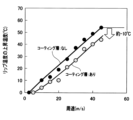
- 10 is a graph showing the results of evaluating the relationship between the peripheral speed of a rotating shaft and the rise in lip temperature.
- FIG. 6 is a graph showing the results of evaluating the relationship between the circumferential speed of the rotating shaft and the rise in lip temperature when different amounts of oil are used.
- 1 is a graph showing the results of an evaluation of the relationship between the amount of oil and the time until an oil leak occurs.
- FIG. 13 is a diagram showing a schematic structure of a coating layer according to a modified example of the present disclosure.
- Embodiment Fig. 1 is a diagram illustrating an example of a structure of a sealing device 1 according to an embodiment of the present disclosure.
- the sealing device 1 is an annular member.
- Fig. 1 illustrates the structure of the sealing device 1 in a partial section of the annular ring in a circumferential direction A.
- the sealing device 1 is disposed between the housing 2 and the rotating shaft 4, and seals the gap ⁇ between the housing 2 and the rotating shaft 4.
- the housing 2 is an example of an external member
- the rotating shaft 4 is an example of an internal member disposed inside the external member.
- the housing 2 and the rotating shaft 4 are members that can rotate relative to each other in both the forward and reverse directions. More specifically, the housing 2 has an axial hole portion 2A with a cylindrical through hole, and the cylindrical rotating shaft 4 is inserted into this axial hole portion 2A, and the rotating shaft 4 rotates in both the forward and reverse directions within this axial hole portion 2A.
- the axis along the center of the axial hole portion 2A is referred to as the "center axis C".
- the circumferential direction A is a direction along the circumference of an imaginary circle of any diameter centered on the center axis C.
- the sealing device 1 is an annular member that surrounds the rotating shaft 4 along the circumferential direction A.
- the sealing device 1 is disposed in the gap ⁇ formed between the shaft hole portion 2A and the rotating shaft 4, thereby dividing the gap ⁇ into an internal space Si and an external space So, and sealing the internal space Si.
- the internal space Si in this embodiment is a space in which a liquid contained within the housing 2 exists, and the external space So is a space outside the housing 2.
- the liquid present in the internal space Si is typically oil, which is an example of a lubricant.
- the oil may also be grease, which has a relatively high viscosity and therefore becomes semi-liquid at room temperature.
- the external space So is typically a space open to the atmosphere.
- the sealing device 1 in this embodiment is also called an "oil seal" that seals the internal space Si in which a liquid such as oil exists.
- the sealing device 1 includes an elastic ring 10, a reinforcing ring 20, and a garter spring 30.
- the elastic ring 10, the reinforcing ring 20, and the garter spring 30 are all circular ring-shaped members.
- the elastic ring 10 is provided on the reinforcing ring 20 and is a molded body made mainly of an elastic material.
- the elastic ring 10 has an annular seal lip 120.
- the seal lip 120 comes into contact with the inner rotating shaft 4 to seal the gap ⁇ .
- the elastic material examples include chloroprene rubber (CR), silicone rubber (SR), acrylic rubber (ACM), urethane rubber (U), polyurethane rubber (PUR), vinyl methyl silicone rubber (VMQ), ethylene propylene diene rubber (EPDM), and fluororubber (FKM).
- fluororubber which has relatively high heat resistance among these elastic materials, is used as the main material of the elastic ring 10.
- fluororubber which has relatively high heat resistance among these elastic materials, is used as the main material of the elastic ring 10. The detailed configuration of the elastic ring 10 will be described later.
- the reinforcing ring 20 is a structure that reinforces the elastic ring 10, and is an example of a metal ring in this disclosure.
- the reinforcing ring 20 is a highly rigid annular member whose main material is, for example, a metal material. Examples of metal materials that can be used include stainless steel, SPCC (Steel Plate Cold Commercial), and SPHC (Steel Plate Hot Commercial).
- the reinforcing ring 20 of this embodiment has an L-shaped cross-sectional shape.
- the reinforcing ring 20 has a cylindrical portion 201 and a flange-shaped portion 202.
- the cylindrical portion 201 is a cylindrical portion extending along the central axis C.
- the inner peripheral surface 201Sa of the cylindrical portion 201 faces the outer peripheral surface of the rotating shaft 4.
- the flange-shaped portion 202 is a portion of the cylindrical portion 201 that extends from the end portion 201T of the cylindrical portion 201 that is close to the external space So toward the central axis C.
- the cylindrical portion 201 and the flange-shaped portion 202 form an L-shaped cross-sectional shape.
- the outer peripheral surface of the cylindrical portion 201 is in close contact with the elastic ring 10, and the tip portion 202T of the flange-shaped portion 202 is embedded in the elastic ring 10, so that the reinforcing ring 20 and the elastic ring 10 are inseparably joined.
- Such a joining structure can be obtained, for example, by insert molding using the reinforcing ring 20 as an insert part.
- the garter spring 30 is a spring member that presses the seal lip 120 of the elastic ring 10 in the direction of the central axis C. More specifically, the garter spring 30 is wound around the seal lip 120 at a position opposite the rotating shaft 4 as viewed from the seal lip 120, and presses the seal lip 120 in the direction of the central axis C by tightening it with the spring elasticity. This pressing ensures an appropriate contact pressure between the seal lip 120 and the rotating shaft 4. Note that the sealing device 1 does not necessarily have to include the garter spring 30.
- the elastic ring 10 has a substantially C-shaped cross section, and the reinforcing ring 20 is fixed inside the elastic ring 10.
- the elastic ring 10 includes three parts: a first cylindrical portion 101, a second cylindrical portion 102, and a connecting portion 103.
- the first cylindrical portion 101 and the second cylindrical portion 102 are both cylindrical portions extending along the central axis C.
- the diameter of the first cylindrical portion 101 is larger than the diameter of the second cylindrical portion 102, and the first cylindrical portion 101 is located outside the second cylindrical portion 102.
- the outer peripheral surface 101Sb of the first cylindrical portion 101 contacts the shaft hole portion 2A of the housing 2, and the inner peripheral surface 102Sa of the second cylindrical portion 102 contacts the rotating shaft 4.
- the connecting portion 103 is a portion that connects the lower end portion 101T of the first cylindrical portion 101 and the lower end portion 102T of the second cylindrical portion 102.
- the connecting portion 103 is shaped like an annular plate of a substantially constant thickness.
- the first cylindrical portion 101, the second cylindrical portion 102, and the connecting portion 103 form the above-mentioned substantially C-shaped cross-sectional shape.
- the sealing device 1 is installed in the gap ⁇ with the open portion of this substantially C-shaped cross-sectional shape facing the internal space Si.
- the cylindrical portion 201 of the reinforcing ring 20 is fixed in close contact with the inner surface 101Sa of the first cylindrical portion 101.
- the flange-shaped portion 202 of the reinforcing ring 20 is fixed in close contact with the upper surface 103Sa of the connecting portion 103.
- the tip portion 202T of this flange-shaped portion 202 is embedded in the outer peripheral surface 102Sb of the second cylindrical portion 102. Due to this fixing structure between the elastic ring 10 and the reinforcing ring 20, when the sealing device 1 is installed, the shape of the first cylindrical portion 101 of the elastic ring 10 and the shape of the connecting portion 103 are maintained even when sandwiched between the housing 2 and the rotating shaft 4.
- the inner circumferential surface 102Sa of the second cylindrical portion 102 includes two structures: a seal lip 120 and a dust lip 130. Both the seal lip 120 and the dust lip 130 are annular portions having a cross-sectional shape that protrudes toward the central axis C.
- the seal lip 120 is disposed in a position facing the internal space Si in the second cylindrical portion 102, and contacts the rotating shaft 4 at that position. The contact of the seal lip 120 with the rotating shaft 4 separates the gap ⁇ into the internal space Si and the external space So, and seals the internal space Si. This sealing by the seal lip 120 prevents liquid from flowing out from the internal space Si to the external space So.
- the dust lip 130 is disposed in a position in the second cylindrical portion 102 facing the external space So, and contacts the rotating shaft 4 at that position. The contact of the dust lip 130 with the rotating shaft 4 prevents foreign matter such as dust and dirt from entering the internal space Si from the external space So.
- a ring-shaped groove 1020 is provided on the outer peripheral surface 102Sb of the second cylindrical portion 102 at a position corresponding to the seal lip 120 on the inner peripheral surface 102Sa (more precisely, at the same height position).
- the above-mentioned garter spring 30 is fitted into this groove 1020, so that the seal lip 120 is pressed against the rotating shaft 4 with an appropriate force by the garter spring 30, sealing the gap ⁇ .
- a sealing device 1 having such a configuration can be installed on any mechanical component, and one example of a suitable mechanical component is a vehicle component.
- vehicle components include a rotating shaft that transmits the output of a prime mover mounted on a vehicle, and this embodiment is also applied to this type of vehicle component.
- the prime mover of a vehicle may be an internal combustion engine, an electric motor, or a hybrid of an internal combustion engine and an electric motor.
- the use of electric motors for prime movers has progressed in the field of automobiles, and many electric vehicles have been developed.
- the maximum vehicle speed of electric vehicles is increasing year by year, and the rotational speed of the output shaft of the prime mover is also steadily increasing.
- FIG. 2 is a schematic diagram showing the configuration of a reduction gear D1, which is a type of vehicle component, together with an electric motor D2.
- the reduction gear D1 has a housing D1A, an input portion D1C including a first rotating shaft D1B1 rotated by the power of the electric motor D2, and an output portion D1D including a second rotating shaft D1B2 that outputs to the outside of the housing D1A.
- An oil seal is provided on each of the input portion D1C and the output portion D1D.
- the rotation speed of the first rotating shaft D1B1 and the second rotating shaft D1B2 can reach a maximum peripheral speed of 50 m/s in the forward direction when the electric vehicle is moving forward, and a maximum peripheral speed of 20 m/s in the reverse direction when moving backward.
- the sealing device 1 of this embodiment is configured so that the seal lip 120 can withstand sliding of the first rotating shaft D1B1 and the second rotating shaft D1B2, which rotate at high speeds, even when used as oil seals for the input portion D1C and the output portion D1D of such a reducer D1. This reduces the occurrence of oil leakage.
- the sealing device 1 of this embodiment is configured to contribute to fuel saving and power saving of the vehicle.
- the sealing device 1 of this embodiment may also be used as an oil seal that seals between the first rotating shaft D1B1 and the housing D1A.
- the sealing device 1 of this embodiment has a configuration that suppresses both the rise in lip temperature caused by heat generated by sliding when the rotating shaft 4 rotating at high speed slides, and the torque of the rotating shaft 4 when the seal lip 120 comes into contact, compared to conventional sealing devices 1.
- the lip temperature is the surface temperature of the seal lip 120.
- suppressing the rise in lip temperature suppresses the occurrence of defects in the seal lip 120, and also suppresses the occurrence of oil leaks caused by the defects.
- suppressing the torque by the sealing device 1 provides the effects of fuel saving and power saving in the vehicle.
- the configuration of the sealing device 1 is explained in more detail below.
- the seal lip 120 of this embodiment includes a first inclined surface 120S1 and a second inclined surface 120S2 that intersect with each other at a position close to the rotation axis 4.
- the first inclined surface 120S1 and the second inclined surface 120S2 form a substantially triangular cross-sectional shape.
- the location where the first inclined surface 120S1 and the second inclined surface 120S2 intersect is referred to as the "tip portion 120T.”
- the diameter ⁇ of the elastic ring 10 is represented by the diameter in a horizontal cross section cut by a plane perpendicular to the central axis C at the tip portion 120T of the seal lip 120, and in this embodiment, the diameter ⁇ of the elastic ring 10 is 95 mm.
- the first inclined surface 120S1 of the seal lip 120 faces the internal space Si.
- the oil in the internal space Si comes into contact with the first inclined surface 120S1, and an oil film is formed on the surface.
- the oil film reduces the coefficient of friction of the first inclined surface 120S1, suppressing an increase in sliding resistance as the speed of the rotating shaft 4 increases, and suppressing sliding heat generation.
- the second inclined surface 120S2 of the seal lip 120 faces the dust lip 130 and the external space So.
- the second inclined surface 120S2 is exposed to the external space So, and therefore its surface is more likely to dry out than the first inclined surface 120S1. Therefore, unless any measures are taken, the sliding heat generated on the second inclined surface 120S2 also increases as the speed of the rotating shaft 4 increases. Therefore, in this embodiment, almost the entire surface of the second inclined surface 120S2 is covered with a coating layer 400 to reduce the friction coefficient between the second inclined surface 120S2 and the rotating shaft 4.
- the coating layer 400 can also be said to be a layer whose friction coefficient with the rotating shaft 4 is lower than that of the main material of the second inclined surface 120S2.
- the coating layer 400 suppresses the sliding heat generated on the second inclined surface 120S2. Furthermore, the coating layer 400 reduces the friction coefficient of the second inclined surface 120S2, thereby reducing the torque of the rotating shaft 4.
- the seal lip 120 of this embodiment includes a first inclined surface 120S1 and a second inclined surface 120S2.
- the first inclined surface 120S1 comes into contact with the oil in the internal space Si, and the friction coefficient is reduced by the oil film.
- the second inclined surface 120S2 has a friction coefficient reduced by the coating layer 400.
- the main material of the elastic ring 10 including the seal lip 120 is fluororubber, which has high heat resistance, so the durability of the seal lip 120 against the lip temperature is improved.
- FIG. 3 is a schematic diagram showing the cross-sectional structure of the seal lip 120.
- the coating layer 400 is a layer including a binder layer 401 having a thickness ⁇ and a plurality of particles 402 dispersed in the binder layer 401, and has a friction coefficient smaller than that of at least the solid surface of the second inclined surface 120S2.
- the main material of the binder layer 401 is, for example, a resin material, which in this embodiment is a mixture of polybutadiene, polyethylene, and butyl acetate.
- the main material of the particles 402 is, for example, a resin material, which in this embodiment is PTFE (Polytetrafluoroethylene), a type of fluororesin.
- An example of a method for manufacturing such a coating layer 400 is as follows. That is, first, in the first step, a mixed material is prepared by mixing particles 402 at a predetermined dispersion density with a resin material, which is the main material of the binder layer 401. Next, in the second step, the second inclined surface 120S2 is coated with the mixed material. Specifically, the mixed material is applied to a thickness ⁇ over substantially the entire surface of the second inclined surface 120S2. After that, in the third step, the mixed material is dried and hardened. Through this series of steps, the coating layer 400 is provided on the surface of the second inclined surface 120S2.
- the thickness ⁇ of the coating layer 400 is 10 ⁇ m ⁇ several ⁇ m. If the thickness ⁇ is greater than 10 ⁇ m, the difference in the hardening state between the surface and deeper parts of the coating layer 400 becomes large during drying in the third step, and wrinkle-like unevenness is likely to occur on the surface of the coating layer 400. If unevenness occurs on the surface, the smoothness decreases, leading to an increase in the friction coefficient and hindering the effect of reducing sliding heat and torque. In addition, it becomes difficult for the deformation of the coating layer 400 to follow the deformation of the seal lip 120 during installation, and defects such as cracks are likely to occur in the coating layer 400 due to the deformation of the seal lip 120.
- the thickness ⁇ is less than 10 ⁇ m, the second inclined surface 120S2 will be easily exposed early due to wear caused by the rotating shaft 4. Furthermore, cracks will easily occur on the surface of the coating layer 400 during drying in the third step, significantly impairing durability.
- the thickness ⁇ of the coating layer 400 is set to 10 ⁇ m, a sufficiently low coefficient of friction and sufficient durability can be obtained against the rotating shaft 4 rotating at high speed.
- the dispersion density of the particles 402 is a preset value that provides a target friction coefficient. If the dispersion density is lower than the preset value, the proportion of non-particle portions on the surface of the coating layer 400, i.e., the proportion of the binder layer 401, increases, so the friction coefficient does not decrease and sufficient reduction in sliding resistance cannot be achieved.
- the seal lip 120 is curved due to contact with the rotating shaft 4, as shown in the conceptual diagram of FIG. 4, for example, the distance between the particles 402 increases, increasing the friction coefficient, and inhibiting the effect of reducing sliding heat generation and torque.
- the particles 402 are uniformly dispersed in the binder layer 401. However, the particles 402 may be non-uniformly dispersed as long as the friction coefficient is not affected.
- a return portion 500 is provided on the surface of the second inclined surface 120S2 of the seal lip 120 in this embodiment.
- the return portion 500 is a portion that returns oil that leaks from the internal space Si to the external space So back to the internal space Si.
- the return portion 500 includes a plurality of protrusions 501.
- the plurality of protrusions 501 bring about a so-called “pumping action" in which oil leaking from the internal space Si to the external space So is returned to the internal space Si in association with the relative rotation between the housing 2 and the rotating shaft 4.
- the shape of the plurality of protrusions 501 is appropriate.
- the plurality of protrusions 501 may be a plurality of spiral ribs as disclosed in Japanese Patent No. 6961094, or a plurality of triangular protrusions as disclosed in Japanese Patent Publication No. 2020-85074.
- the protrusions 501 are an example of a "first protrusion.”
- a dust lip 130 that contacts the entire circumference of the rotating shaft 4 is disposed at a position close to the external space So as viewed from the seal lip 120.
- the space close to the external space So as viewed from the seal lip 120 is separated from the external space So by the dust lip 130.
- the pumping action of the seal lip 120 will cause the space between the seal lip 120 and the dust lip 130 to become negative pressure with respect to the external space So, resulting in a decrease in the pumping action.
- the contact surface 130S of the dust lip 130 that comes into contact with the rotating shaft 4 is provided with a convex portion 600.
- a convex portion 600 For example, multiple convex portions 600 are provided at intervals in the circumferential direction A.
- gaps are generated between the rotating shaft 4 and the contact surface 130S on both sides of the convex portions 600 in the circumferential direction.
- the convex portions 600 are an example of a "second convex portion.”
- a sealing head E16 is provided outside the annular portion E14 and the flange E12 to form a sealed space.
- This sealed space corresponds to the internal space Si, and oil is sealed in this sealed space.
- the rotation axis E11 extends in a substantially horizontal direction. When oil is sealed in to an amount such that the oil level is located on the central axis C of the rotation axis E11, the lower half of the entire circumference of the seal lip 120, which is located vertically below the central axis C, is immersed in oil.
- the amount of oil is expressed by the distance L along the radial direction of the seal lip 120 from a position on the seal lip 120 directly below the central axis C to the position of the oil level, and the distance L is also referred to as the oil amount.
- a low-viscosity ATF Automatic Transmission Fluid
- the oil is used as the oil.
- an oil sensor E17 is attached to the inner circumferential surface of the annular portion E14 at a position near the sealing device 1. If oil leaks from the sealed space past the sealing device 1 into a space close to the oil sensor E17, the oil sensor E17 detects the leaked oil.
- a torque meter E18 is provided on the rotating shaft E11 to measure the torque of the rotating shaft E11. The torque meter E18 detects the torque of the rotating shaft E11 at a predetermined cycle, for example.
- a thermocouple (not shown) is placed on the seal lip 120 of the sealing device 1, and the lip temperature is detected by the thermocouple.
- the torque increases monotonically as the shaft rotation speed increases from 2000 rpm to 8000 rpm.
- the results of this evaluation test show that the torque reduction effect is achieved. Specifically, by providing the coating layer 400 on the seal lip 120, the torque is reduced by at least about 30% or more compared to the case where the coating layer 400 is not provided.
- the lip temperature rise decreases. Specifically, by providing the coating layer 400 on the seal lip 120, the lip temperature rise decreases by approximately 10% at least in the entire range of circumferential speeds from 0 to 50 m/s or less, compared to when the coating layer 400 is not provided. In other words, the effect of reducing sliding heat generation in the seal lip 120 is obtained.
- the oil in the internal space Si helps to suppress the rise in lip temperature, and the smaller the oil amount L, the higher the lip temperature becomes, making it easier for defects to occur in the seal lip 120. This phenomenon will be described in detail below.
- Figure 8 is a graph showing the results of evaluating the relationship between the circumferential speed (unit: m/s) of the rotating shaft E11 and the lip temperature rise (unit: °C) for different oil amounts L. This evaluation test was conducted in an environment where the oil temperature was set to 80 °C.
- the lip temperature increases significantly in proportion to the circumferential speed, and when the circumferential speed is 50 m/s, the lip temperature increases to approximately 55°C.
- Figure 9 is a graph showing the results of an evaluation of the relationship between the amount of oil L (unit: mm) and the time (unit: hours) until oil leakage occurs. This evaluation test was performed using a sealing device 1 without a coating layer 400 as a sample, with the oil temperature at 150°C, and the shaft rotation speed of the rotating shaft E11 varied in the range from 0 to 15,000 rpm.
- the inventors observed samples after testing in which the lip temperature had reached 200°C, causing oil leakage. As a result of the observations, they found that defects such as cracks and blisters had occurred on the surface of the seal lip 120, and that these were factors that caused early oil leakage.
- a sealing device 1 that does not have a coating layer 400
- the lip temperature rises significantly depending on the circumferential speed; for example, when the oil amount L is 15 mm, the lip temperature rises to approximately 55°C when the circumferential speed is 50 m/s.
- the oil temperature is 150°C, the lip temperature reaches 200°C, and the time until oil leakage is exponentially shortened to approximately 10 hours.
- the sealing device 1 of this embodiment is provided with the coating layer 400, which suppresses the rise in lip temperature as shown in FIG. 7, so that the rise in lip temperature is suppressed even when the oil amount L is less than ⁇ /2. As a result, the time until oil leakage occurs is shortened, i.e., the shortening of the lifespan is suppressed.
- the sealing device 1 of this embodiment can further extend the life by reducing the lip temperature.
- the sealing device 1 of this embodiment includes an annular reinforcing ring 20 and an annular seal lip 120 provided on the reinforcing ring 20.
- the seal lip 120 is inserted inside the rotating shaft 4 that rotates in the forward and reverse directions, and is configured to be in contact with the rotating shaft 4 and to withstand the sliding of the rotating shaft 4 that rotates at a peripheral speed of 50 m/s.
- the sealing device 1 can withstand use even when the rotating shaft 4 rotates at a high speed of up to a peripheral speed of 50 m/s. This provides a sealing device 1 that can meet the demand for high speed rotation of the rotating shaft 4.
- the seal lip 120 is provided with a coating layer 400 to reduce the coefficient of friction between it and the rotating shaft 4.
- sliding heat generation in the seal lip 120 is suppressed even when the rotating shaft 4 rotates at high speed and slides.
- the rise in lip temperature is suppressed, and deterioration of the seal lip 120 caused by the rise in lip temperature can be suppressed.
- the torque of the rotating shaft 4 is also reduced, which contributes to lower fuel consumption and power consumption of the mechanism that drives the rotating shaft 4.
- the seal lip 120 divides the gap ⁇ between the rotating shaft 4 and the housing 2, which is an example of an external member, into an internal space Si where oil is present and an external space So, and includes a first inclined surface 120S1 and a second inclined surface 120S2 that intersect at their tips.
- the first inclined surface 120S1 faces the internal space Si
- the second inclined surface 120S2 faces the external space So, and is covered with a coating layer 400.
- the first inclined surface 120S1 of the seal lip 120 comes into contact with the oil in the internal space Si, and the friction coefficient is reduced by the oil film.
- the friction coefficient of the second inclined surface 120S2 is reduced by the coating layer 400. This reduces the generation of heat due to sliding on each of the first inclined surface 120S1 and the second inclined surface 120S2, and effectively prevents the lip temperature from rising.
- the coating layer 400 is a layer in which fluororesin particles 402 are dispersed in a binder layer 401.
- the fluororesin particles 402 can sufficiently reduce the above-mentioned coefficient of friction.
- the main material of the seal lip 120 is fluororubber. This configuration increases the durability of the seal lip 120 against lip temperature.
- the second inclined surface 120S2 includes a return portion 500 that returns the oil moving from the internal space Si to the external space So to the internal space Si, and this return portion 500 includes a plurality of protrusions 501.
- the plurality of protrusions 501 are covered by the above-mentioned coating layer 400.
- the dust lip 130 is provided at a position close to the external space So as viewed from the second inclined surface 120S2 and is in contact with the rotating shaft 4.
- the dust lip 130 is provided with a protrusion 600 for ensuring a gap between the dust lip 130 and the rotating shaft 4. According to this configuration, the space between the seal lip 120 and the dust lip 130 is connected to the external space So through the gap created by the convex portion 600, thereby preventing the space from becoming negative pressure and suppressing a decrease in the pumping action.
- the coating layer 400 is provided on the second inclined surface 120S2 of the seal lip 120 in addition to the second inclined surface 120S2.
- the coating layer 400 may be provided on at least one of the first inclined surface 120S1 and the contact surface 130S of the dust lip 130 in addition to the second inclined surface 120S2.
- the coating layer 400 on the first inclined surface 120S1 By providing the coating layer 400 on the first inclined surface 120S1, the coefficient of friction of the first inclined surface 120S1 is further reduced, and the generation of heat due to sliding is further reduced.
- the coating layer 400 on the contact surface 130S of the dust lip 130 the lubricity of the protrusions 600 is increased, making it easier for gaps to form.
- the coating layer 400 may include an adhesive layer 403 for improving adhesion with the second inclined surface 120S2 of the seal lip 120, as shown in FIG. 10.
- the adhesive layer 403 may be made of, for example, a resin material that is the main material of the binder layer 401. Because the adhesive layer 403 does not contain PTFE particles 402, the contact area between the resin material that is the main material of the binder layer 401 and the second inclined surface 120S2 is increased, and adhesion is improved.
- the seal lip 120 can withstand the sliding of the rotating shaft 4 rotating at a peripheral speed of 50 m/s, but the peripheral speed of the rotating shaft 4 that the seal lip 120 can withstand is not limited to the above example.
- the seal lip 120 may be configured to withstand the sliding of the rotating shaft 4 rotating at a peripheral speed in the range of -30 m/s or more and 80 m/s or less.
- the seal lip 120 may be configured to contact the rotating shaft 4 and withstand the sliding of the rotating shaft 4 rotating at a peripheral speed of 80 m/s.
- the sealing device 1 is used as an oil seal.
- the use of the sealing device 1 is arbitrary.
- the sealing device 1 may be used for any purpose, such as an engine oil seal, a differential oil seal, a transmission oil seal, a motor oil seal, or a hub bearing oil seal.
- the sealing device 1 may also be used for purposes other than an oil seal.
- the sealing device 1 may be used for sealing various fluids such as grease or water.
- 1...sealing device 2...housing (external member), 4...rotating shaft, 10...elastic ring, 20...reinforcing ring (metal ring), 30...garter spring, 120...seal lip, 120S1...first inclined surface, 120S2...second inclined surface, 120T...tip portion, 130...dust lip, 130S...contact surface, 400...coating layer, 401...binder layer, 402...particles, 403...adhesive layer, 500...return portion, 501...projection portion, 600...projection portion, Si...internal space, So...external space, ⁇ ...gap.
Landscapes
- Engineering & Computer Science (AREA)
- General Engineering & Computer Science (AREA)
- Mechanical Engineering (AREA)
- Physics & Mathematics (AREA)
- Fluid Mechanics (AREA)
- Sealing With Elastic Sealing Lips (AREA)
Priority Applications (4)
| Application Number | Priority Date | Filing Date | Title |
|---|---|---|---|
| CN202380076158.4A CN120153193A (zh) | 2022-11-17 | 2023-11-14 | 密封装置 |
| US19/130,608 US20260085754A1 (en) | 2022-11-17 | 2023-11-14 | Sealing device |
| JP2024558882A JPWO2024106416A1 (https=) | 2022-11-17 | 2023-11-14 | |
| EP23891563.1A EP4621268A1 (en) | 2022-11-17 | 2023-11-14 | Sealing device |
Applications Claiming Priority (2)
| Application Number | Priority Date | Filing Date | Title |
|---|---|---|---|
| JP2022-184137 | 2022-11-17 | ||
| JP2022184137 | 2022-11-17 |
Publications (1)
| Publication Number | Publication Date |
|---|---|
| WO2024106416A1 true WO2024106416A1 (ja) | 2024-05-23 |
Family
ID=91084854
Family Applications (1)
| Application Number | Title | Priority Date | Filing Date |
|---|---|---|---|
| PCT/JP2023/040882 Ceased WO2024106416A1 (ja) | 2022-11-17 | 2023-11-14 | 密封装置 |
Country Status (5)
| Country | Link |
|---|---|
| US (1) | US20260085754A1 (https=) |
| EP (1) | EP4621268A1 (https=) |
| JP (1) | JPWO2024106416A1 (https=) |
| CN (1) | CN120153193A (https=) |
| WO (1) | WO2024106416A1 (https=) |
Citations (7)
| Publication number | Priority date | Publication date | Assignee | Title |
|---|---|---|---|---|
| JP2002323144A (ja) * | 2001-04-26 | 2002-11-08 | Hitachi Ltd | 流体機械のラビリンスシール |
| JP2004044745A (ja) * | 2002-07-15 | 2004-02-12 | Mitsubishi Cable Ind Ltd | 回転軸シール |
| JP2015072033A (ja) * | 2013-10-02 | 2015-04-16 | Nok株式会社 | オイルシール |
| JP2019210998A (ja) | 2018-06-04 | 2019-12-12 | Nok株式会社 | 密封装置 |
| JP2020085074A (ja) | 2018-11-20 | 2020-06-04 | Nok株式会社 | 密封装置 |
| JP6961094B2 (ja) | 2018-08-28 | 2021-11-05 | Nok株式会社 | 密封装置 |
| WO2022059360A1 (ja) * | 2020-09-15 | 2022-03-24 | Nok株式会社 | 密封装置 |
Family Cites Families (5)
| Publication number | Priority date | Publication date | Assignee | Title |
|---|---|---|---|---|
| US6676132B1 (en) * | 1999-09-27 | 2004-01-13 | Kojo Seiko Co., Ltd. | Seal and rotary assembly using the seal |
| CN101652588B (zh) * | 2007-04-11 | 2013-08-28 | Nok株式会社 | 油封件 |
| JP6384952B2 (ja) * | 2014-09-09 | 2018-09-05 | 株式会社ジェイテクト | 摺動部材 |
| EP3951218A4 (en) * | 2019-03-29 | 2022-11-16 | NOK Corporation | SEALING DEVICE |
| EP4006114A4 (en) * | 2019-07-25 | 2023-08-09 | NOK Corporation | COATING AGENT FOR OIL SEAL |
-
2023
- 2023-11-14 US US19/130,608 patent/US20260085754A1/en active Pending
- 2023-11-14 CN CN202380076158.4A patent/CN120153193A/zh active Pending
- 2023-11-14 JP JP2024558882A patent/JPWO2024106416A1/ja active Pending
- 2023-11-14 WO PCT/JP2023/040882 patent/WO2024106416A1/ja not_active Ceased
- 2023-11-14 EP EP23891563.1A patent/EP4621268A1/en active Pending
Patent Citations (7)
| Publication number | Priority date | Publication date | Assignee | Title |
|---|---|---|---|---|
| JP2002323144A (ja) * | 2001-04-26 | 2002-11-08 | Hitachi Ltd | 流体機械のラビリンスシール |
| JP2004044745A (ja) * | 2002-07-15 | 2004-02-12 | Mitsubishi Cable Ind Ltd | 回転軸シール |
| JP2015072033A (ja) * | 2013-10-02 | 2015-04-16 | Nok株式会社 | オイルシール |
| JP2019210998A (ja) | 2018-06-04 | 2019-12-12 | Nok株式会社 | 密封装置 |
| JP6961094B2 (ja) | 2018-08-28 | 2021-11-05 | Nok株式会社 | 密封装置 |
| JP2020085074A (ja) | 2018-11-20 | 2020-06-04 | Nok株式会社 | 密封装置 |
| WO2022059360A1 (ja) * | 2020-09-15 | 2022-03-24 | Nok株式会社 | 密封装置 |
Non-Patent Citations (1)
| Title |
|---|
| See also references of EP4621268A1 |
Also Published As
| Publication number | Publication date |
|---|---|
| US20260085754A1 (en) | 2026-03-26 |
| EP4621268A1 (en) | 2025-09-24 |
| JPWO2024106416A1 (https=) | 2024-05-23 |
| CN120153193A (zh) | 2025-06-13 |
Similar Documents
| Publication | Publication Date | Title |
|---|---|---|
| US6726212B2 (en) | Retrofittable severe duty seal for a shaft | |
| JP4966072B2 (ja) | ラジアルシャフトシール | |
| US20040056427A1 (en) | Lip seal | |
| CN109690101B (zh) | 带密封轴承 | |
| JP2011174570A (ja) | 密封装置 | |
| US20200166138A1 (en) | Sealing apparatus | |
| CN112585383A (zh) | 径向轴密封件 | |
| US8651496B2 (en) | Seal | |
| WO2013077010A1 (ja) | 密封装置 | |
| JP5839509B2 (ja) | 密封装置及び密封構造 | |
| WO2024106416A1 (ja) | 密封装置 | |
| JP7203723B2 (ja) | 密封装置 | |
| JP7644771B2 (ja) | 密封装置 | |
| JP5479771B2 (ja) | 密封装置 | |
| JP2018091372A (ja) | 密封装置 | |
| JP5092166B2 (ja) | シャフトシール装置 | |
| US9360116B2 (en) | Seal and method for manufacturing thereof | |
| JP2010060120A (ja) | 密封装置 | |
| WO2022210480A1 (ja) | 密封構造および密封方法 | |
| JP2019015354A (ja) | 密封装置 | |
| JPH0960732A (ja) | ウオーターポンプのシール構造 | |
| JP2017089701A (ja) | 密封装置 | |
| JP2019015352A (ja) | 密封装置 | |
| CN108779860A (zh) | 密封圈 | |
| JPH07174238A (ja) | シール構造 |
Legal Events
| Date | Code | Title | Description |
|---|---|---|---|
| 121 | Ep: the epo has been informed by wipo that ep was designated in this application |
Ref document number: 23891563 Country of ref document: EP Kind code of ref document: A1 |
|
| WWE | Wipo information: entry into national phase |
Ref document number: 202380076158.4 Country of ref document: CN |
|
| WWE | Wipo information: entry into national phase |
Ref document number: 2024558882 Country of ref document: JP |
|
| WWP | Wipo information: published in national office |
Ref document number: 202380076158.4 Country of ref document: CN |
|
| WWE | Wipo information: entry into national phase |
Ref document number: 2023891563 Country of ref document: EP |
|
| NENP | Non-entry into the national phase |
Ref country code: DE |
|
| ENP | Entry into the national phase |
Ref document number: 2023891563 Country of ref document: EP Effective date: 20250617 |
|
| WWP | Wipo information: published in national office |
Ref document number: 2023891563 Country of ref document: EP |