WO2024106084A1 - バルーンカテーテル用バルーンおよびバルーンカテーテル - Google Patents
バルーンカテーテル用バルーンおよびバルーンカテーテル Download PDFInfo
- Publication number
- WO2024106084A1 WO2024106084A1 PCT/JP2023/036995 JP2023036995W WO2024106084A1 WO 2024106084 A1 WO2024106084 A1 WO 2024106084A1 JP 2023036995 W JP2023036995 W JP 2023036995W WO 2024106084 A1 WO2024106084 A1 WO 2024106084A1
- Authority
- WO
- WIPO (PCT)
- Prior art keywords
- balloon
- ridge
- straight tube
- drug layer
- section
- Prior art date
- Legal status (The legal status is an assumption and is not a legal conclusion. Google has not performed a legal analysis and makes no representation as to the accuracy of the status listed.)
- Ceased
Links
Images





Classifications
-
- A—HUMAN NECESSITIES
- A61—MEDICAL OR VETERINARY SCIENCE; HYGIENE
- A61M—DEVICES FOR INTRODUCING MEDIA INTO, OR ONTO, THE BODY; DEVICES FOR TRANSDUCING BODY MEDIA OR FOR TAKING MEDIA FROM THE BODY; DEVICES FOR PRODUCING OR ENDING SLEEP OR STUPOR
- A61M25/00—Catheters; Hollow probes
- A61M25/10—Balloon catheters
Definitions
- the present invention relates to a balloon for a balloon catheter with a drug retained on its surface and a balloon catheter equipped with the balloon.
- stenosis in blood vessels which are the channels through which blood circulates in the body
- blood vessels which are the channels through which blood circulates in the body
- stenosis in the coronary arteries that supply blood to the heart can lead to serious diseases such as angina pectoris and myocardial infarction.
- angioplasty PTA, PTCA, etc.
- PTA angioplasty
- PTCA PTCA
- Balloon catheters with ridges on the surface of the balloon are known (see, for example, Patent Documents 1 to 5).
- the ridges of the balloon can be inserted into the narrowed area when the balloon is inflated, effectively expanding the narrowed area.
- restenosis can occur at the expanded narrowed area, and balloon catheters with a drug retained on the balloon surface are also known to reduce the frequency of such restenosis (restenosis rate) (see, for example, Patent Documents 4 to 7).
- the drug can be transferred to the inner wall of the body cavity, such as the blood vessel wall, by expanding the balloon at the narrowed or diseased area of the body cavity, such as a blood vessel, and it is expected that the occurrence of restenosis, etc. can be suppressed.
- a balloon catheter with a drug retained on the balloon surface can efficiently transfer the drug to the inner wall of a body cavity such as a blood vessel wall by expanding the balloon at a narrowed or affected area of a body cavity such as a blood vessel.
- the present invention has been made in consideration of the above circumstances, and its purpose is to provide a balloon for a balloon catheter that can efficiently transfer a drug to a narrowed or affected area of a body cavity such as a blood vessel, and a balloon catheter equipped with the balloon.
- a balloon for a balloon catheter having a longitudinal direction extending from a proximal side to a distal side and a radial direction perpendicular to the longitudinal direction,
- the balloon has a straight tube portion, a proximal tapered portion located proximally of the straight tube portion, and a distal tapered portion located distally of the straight tube portion
- the straight pipe portion has a cylindrical balloon main body and a protrusion protruding radially outward on an outer surface of the balloon main body, and a protrusion-existing region and a protrusion-free region are formed on the outer surface of the straight pipe portion
- a drug layer is provided on the outer surface of the straight tube portion
- a balloon for a balloon catheter wherein, in a vertical cross section of the straight tube portion in the longitudinal direction, the average thickness of the drug layer in the non-ridge area is
- the balloon for balloon catheter of the present invention has ridges on the outer surface of the straight tube part of the balloon, and a relatively thick drug layer is provided in the areas of the straight tube part where there are no ridges. Therefore, when a balloon catheter equipped with the balloon of the present invention is used to expand the balloon at a narrowed or affected part of a body cavity such as a blood vessel, the ridges bite into the narrowed or affected part, allowing for effective expansion, and the drug held on the surface of the balloon at the expanded narrowed or affected part can be efficiently transferred to the inner surface of the inner wall of the body cavity such as the blood vessel wall.
- FIG. 1 shows an example of the configuration of a balloon catheter according to an embodiment of the present invention, and is a side view of the balloon catheter excluding the drug layer on the balloon surface.
- FIG. 2 is a perspective view of a balloon provided in the balloon catheter shown in FIG. 1 .
- 3 shows a cross-sectional view of the balloon catheter shown in FIG. 1 taken along line III-III.
- 4 shows a cross-sectional view of the balloon catheter shown in FIG. 1 taken along line IV-IV.
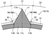
- 1 shows an example of a vertical cross-sectional view of a straight portion of a balloon with a drug layer in the longitudinal direction.
- 6 is an enlarged cross-sectional view of the ridges and their surroundings of the balloon shown in FIG. 5 .
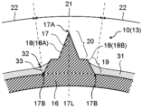
- FIG. 13 shows another example of an enlarged cross-sectional view of the area around the convex ridge of a balloon having a drug layer.
- 1 shows an example of an enlarged cross-sectional view of the periphery of a protruding ridge of a balloon having a drug layer and a lubricating layer.
- 13 shows another example of an enlarged cross-sectional view of the area around the convex ridge of a balloon having a drug layer.
- FIG. 6 illustrates an example of a vertical cross-sectional view in the longitudinal direction of the balloon shown in FIG. 5 in a deflated and folded state.
- FIG. 6 shows another example of a vertical cross-sectional view in the longitudinal direction of the balloon shown in FIG. 5 in a deflated and folded state.
- 11 illustrates another example of a vertical cross-sectional view of the balloon in the folded state shown in FIG. 10.
- FIG. 1 shows a side view of a balloon catheter
- Fig. 2 shows a perspective view of a balloon equipped in the balloon catheter shown in Fig. 1
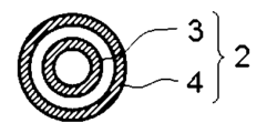
- Fig. 3 shows a III-III cross-sectional view of the balloon catheter shown in Fig. 1
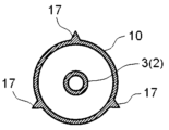
- Fig. 4 shows an IV-IV cross-sectional view of the balloon catheter shown in Fig. 1.
- Fig. 1 shows an example of the configuration of a rapid exchange type balloon catheter.
- the balloon catheter 1 has a shaft 2 and a balloon 10 provided on the outside of the shaft 2.
- the balloon catheter 1 has a proximal side and a distal side, and the balloon 10 is provided on the distal part of the shaft 2.
- the proximal side of the balloon catheter 1 refers to the direction toward the user's (operator's) hand in the extension direction of the balloon catheter 1, and the distal side refers to the opposite direction of the proximal side, i.e., the direction toward the treatment target.
- the direction from the proximal side to the distal side of the balloon catheter 1 is referred to as the longitudinal direction.
- the balloon catheter 1 is configured so that fluid is supplied to the inside of the balloon 10 through the shaft 2, and the expansion and contraction of the balloon 10 can be controlled using an indeflator (a balloon pressurizer/depressurizer).
- the fluid may be a pressurized fluid pressurized by a pump or the like.
- the fluid supplied to the inside of the balloon 10 is referred to as the "balloon expansion fluid.”
- the shaft 2 is composed of, for example, an inner shaft 3 and an outer shaft 4.
- the inner shaft 3 is disposed in the inner cavity of the outer shaft 4.
- the inner shaft 3 can function as a passage for a guide wire that guides the progress of the shaft 2, and when the balloon catheter 1 is used, the guide wire is inserted into the inner cavity of the inner shaft 3.
- the space between the inner shaft 3 and the outer shaft 4 can function as a flow path for the balloon expansion fluid.
- a guidewire port 7 is provided midway from the distal to the proximal side of the shaft 2, and the proximal end of the inner shaft 3 is connected to the guidewire port 7, and the distal end of the inner shaft 3 extends to the distal part of the shaft 2, forming a guidewire insertion passage that extends from the guidewire port 7 to the distal part of the shaft 2.
- the outer shaft 4 may have a proximal outer shaft 4A and a distal outer shaft 4B, in which case it is preferable that the inner shaft 3 is disposed in the lumen of the distal outer shaft 4B.
- the proximal outer shaft 4A and the distal outer shaft 4B may be made of the same material, or may be made of different materials.
- the proximal outer shaft 4A is made of resin or metal
- the distal outer shaft 4B is made of resin.
- the outer shaft 4 may not be divided into the proximal outer shaft 4A and the distal outer shaft 4B, but may be made of a single member, or the proximal outer shaft 4A and the distal outer shaft 4B may be further made of multiple tube members.
- a hub 5 is preferably provided on the proximal side of the shaft 2.
- the hub 5 preferably has a fluid injection section 6 that is connected to the flow path of the balloon expansion fluid in the shaft 2.
- the balloon 10, shaft 2 (inner shaft 3, outer shaft 4), and hub 5 can be joined using conventional joining means such as adhesives or heat welding.
- the balloon catheter may be an over-the-wire type balloon catheter in which the inner shaft extends from the distal to the proximal part of the shaft and a guidewire passage is formed from the distal to the proximal side of the shaft.
- the flow path of the balloon expansion fluid and the guidewire passage provided in the shaft extend to the hub, and that the hub is configured to have a fluid injection section communicating with the flow path of the balloon expansion fluid and a treatment section communicating with the guidewire passage.
- the hub has a bifurcated structure, with the fluid injection section provided on one side of the bifurcated branch and the treatment section provided on the other side.
- the outer surface of the shaft 2 is preferably coated.
- a rapid exchange type balloon catheter 1 it is preferable that the outer surface of one or both of the proximal outer shaft 4A and the distal outer shaft 4B is coated, and it is more preferable that the outer surfaces of both the proximal outer shaft 4A and the distal outer shaft 4B are coated.
- an over-the-wire type balloon catheter it is preferable that the outer surface of the outer shaft is appropriately coated.
- the coating can be a hydrophilic coating or a hydrophobic coating depending on the purpose.
- the outer surface of the shaft 2 can be coated by immersing the shaft 2 in a hydrophilic or hydrophobic coating agent, applying a hydrophilic or hydrophobic coating agent to the outer surface of the shaft 2, or covering the outer surface of the shaft 2 with a hydrophilic or hydrophobic coating agent.
- the coating agent may contain drugs or additives.
- Hydrophilic coating agents include hydrophilic polymers such as polyvinyl alcohol, polyethylene glycol, polyacrylamide, polyvinylpyrrolidone, and methyl vinyl ether maleic anhydride copolymers, as well as hydrophilic coating agents made from any combination of these.
- Hydrophobic coating agents include polytetrafluoroethylene (PTFE), fluorinated ethylene propylene (FEP), perfluoroalkoxyalkane (PFA), silicone oil, hydrophobic urethane resin, carbon coat, diamond coat, diamond-like carbon (DLC) coat, ceramic coat, and substances with low surface free energy terminated with alkyl groups or perfluoroalkyl groups.
- PTFE polytetrafluoroethylene
- FEP fluorinated ethylene propylene
- PFA perfluoroalkoxyalkane
- silicone oil silicone oil
- hydrophobic urethane resin carbon coat
- diamond coat diamond coat
- DLC diamond-like carbon
- ceramic coat and substances with low surface free energy terminated with alkyl groups or perfluoroalkyl groups.
- a tip tip 8 is provided at the distal end of the balloon catheter 1.
- the tip tip 8 may be provided as a separate member from the inner shaft 3, distal to the distal end of the inner shaft 3, or the inner shaft 3 may extend distal to the distal end of the balloon 10, so that the distal end of the inner shaft 3 functions as the tip tip 8.
- the shaft 2 may have an X-ray opaque marker 9 disposed at the portion where the balloon 10 is located in the longitudinal direction, so that the position of the balloon 10 can be confirmed under X-ray fluoroscopy.
- the X-ray opaque marker 9 may be disposed, for example, on the inner shaft 3 disposed inside the balloon 10, and is preferably disposed at positions corresponding to both ends of the straight tube portion of the balloon 10, or may be disposed at a position corresponding to the center of the straight tube portion of the balloon 10.
- the balloon 10 has a longitudinal direction and a radial direction, and is formed into a cylindrical shape with openings on the proximal and distal sides (see FIG. 2).
- the radial direction of the balloon 10 means a direction perpendicular to the longitudinal direction, extending radially from the center of the balloon 10.
- the balloon 10 also has a circumferential direction, which is the direction along the outer periphery of the balloon 10 in an expanded state in a vertical cross section of the longitudinal direction of the balloon 10.
- the balloon 10 has a straight tube section 13, a proximal tapered section 12 located proximal to the straight tube section 13, and a distal tapered section 14 located distal to the straight tube section 13 in the longitudinal direction.
- the straight tube section 13 is formed in an approximately cylindrical shape extending in the longitudinal direction, and is formed to have the largest radial length (outer diameter) in the balloon 10.
- the proximal tapered section 12 is located proximal to the straight tube section 13 and connects to the proximal end of the straight tube section 13.
- the proximal tapered section 12 is formed so that the outer diameter decreases with increasing distance from the straight tube section 13.
- the distal tapered section 14 is located distal to the straight tube section 13 and connects to the distal end of the straight tube section 13.
- the distal tapered section 14 is formed so that the outer diameter decreases with increasing distance from the straight tube section 13.
- the balloon 10 preferably further has a proximal sleeve portion 11 located proximal to the proximal taper portion 12 and a distal sleeve portion 15 located distal to the distal taper portion 14.
- the proximal sleeve portion 11 is located proximal to the proximal taper portion 12 and is connected to the proximal end of the proximal sleeve portion 11.
- the proximal sleeve portion 11 is formed in a substantially cylindrical shape.
- the distal sleeve portion 15 is located distal to the distal taper portion 14 and is connected to the distal end of the distal sleeve portion 15.
- the distal sleeve portion 15 is formed in a substantially cylindrical shape.
- the straight tube section 13 comes into sufficient contact with the narrowed area, making it easier to perform treatment such as expanding the narrowed area.
- the balloon 10 has a proximal tapered section 12 and a distal tapered section 14, when the balloon 10 is deflated, the outer diameter of the proximal and distal ends of the balloon 10 can be reduced to reduce the step between the shaft 2 and the balloon 10, making it easier to insert the balloon 10 into a body cavity or a forceps channel of an endoscope.
- the inner shaft 3 extends distally from the distal end of the outer shaft 4, and that the inner shaft 3 extends through the internal space of the balloon 10 from the proximal sleeve portion 11 to the distal sleeve portion 15. It is also preferable that the outer surface of the inner shaft 3 is joined to the internal surface of the distal sleeve portion 15 of the balloon 10, and the outer surface of the outer shaft 4 is joined to the internal surface of the proximal sleeve portion 11 of the balloon 10.
- the balloon 10 is preferably made of a resin, more preferably a thermoplastic resin. This makes it easier to manufacture the balloon 10 by molding.
- resins that make up the balloon 10 include polyolefin resins such as polyethylene, polypropylene, and ethylene-propylene copolymer, polyester resins such as polyethylene terephthalate and polyester elastomer, polyurethane resins such as polyurethane and polyurethane elastomer, polyphenylene sulfide resins, polyamide resins such as polyamide and polyamide elastomer, fluorine-based resins, silicone resins, and natural rubbers such as latex rubber. These may be used alone or in combination of two or more.
- polyamide resins polyester resins, and polyurethane resins are preferably used.
- elastomer resins are preferably used in terms of thinning and flexibility of the balloon 10.
- nylon 12 and nylon 11 are examples of polyamide resins that are suitable for the balloon 10, and nylon 12 is preferably used because it is relatively easy to mold when blow molding.
- polyamide elastomers such as polyether ester amide elastomers and polyamide ether elastomers are preferably used in terms of thinning and flexibility of the balloon 10.
- polyether ester amide elastomers are preferably used because they have high yield strength and provide good dimensional stability to the balloon 10.
- the balloon 10 has a ridge 17 on the outer surface of the straight tube portion 13.
- the ridge 17 on the outer surface of the straight tube portion 13 gives the balloon 10 a scoring function, and when the balloon 10 is expanded at a narrowed portion of a blood vessel, it can bite into the calcified narrowed portion and create a crack in the narrowed portion. This allows the narrowed portion to be expanded while suppressing dissection of the vascular intima. It also makes it possible to increase the strength of the balloon 10 and suppress overexpansion when pressurized.
- the balloon 10 can also be used to treat narrowed portions or lesions in body cavities other than blood vessels, but the following description focuses on the application of the balloon 10 to narrowed portions of blood vessels.
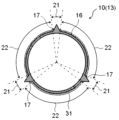
- Figure 5 shows a vertical cross-section in the longitudinal direction of the straight tube section 13 of the balloon 10
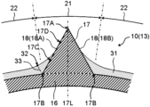
- Figures 6 to 9 show enlarged cross-sections of the ridges 17 and the surrounding area of the balloon 10.
- Figures 5 to 9 show a balloon 10 in which a drug layer 31 is provided on the outer surface of the straight tube section 13.
- Figure 5 shows an example of a configuration in which a drug layer 31 is provided on the outer surface of the balloon 10 shown in Figures 2 and 4, and the ridges 17 are provided at three locations in the circumferential direction of the straight tube section 13.
- the straight tube section 13 of the balloon 10 has a cylindrical balloon main body section 16, and a convex rib 17 is provided on the outer surface of the balloon main body section 16.
- the convex rib 17 is provided so as to protrude radially outward from the outer surface of the balloon main body section 16.
- the balloon 10 has a convex rib region 21 and a convex rib non-existent region 22 formed on the outer surface of the straight tube section 13.
- the ridge 17 has an apex 17A and a base 17B (see Figures 6 to 9).
- the apex 17A refers to the tip of the ridge 17, i.e., the part located most radially outward of the ridge 17, and the base 17B refers to the boundary with the balloon body 16 on the side of the ridge 17, i.e., the part located most radially inward of the ridge 17.
- the ridges 17 can be made of resin, for example. If the ridges 17 are made of resin, the balloon 10 having the ridges 17 can be manufactured by resin molding, making manufacturing easier. In this case, the ridges 17 and the balloon body 16 are preferably made of the same resin, and the ridges 17 and the balloon body 16 are preferably integrally formed.
- the balloon body 16 may have an inner layer and an outer layer, and in this case, the ridges 17 are preferably made of the same resin as the outer layer of the balloon body 16. This makes it less likely that the ridges 17 will unintentionally fall off the balloon body 16.
- the ridges 17 and the balloon body 16 may be made of different resins, as long as there is a certain degree of compatibility between the resin that makes up the ridges 17 and the resin that makes up the balloon body 16.
- the ridges 17 may be made of metal, or a combination of metal and resin. In this case, it is preferable that the portion including the apex 17A of the ridges 17 is made of metal. This makes it easier for the ridges 17 to create a crack in the narrowed area or to cut open the narrowed area when the balloon 10 is inflated.
- the entire ridges 17 may be made of metal, or the portion including the base 17B of the ridges 17 may be made of resin, and the portion including the apex 17A of the ridges 17 may be made of metal. Therefore, it is preferable that the ridges 17 are made of resin, metal, or a combination thereof.
- the balloon main body 16 is defined as a portion having a cylindrical shape.
- the straight pipe section 13 is composed of the balloon main body 16 excluding the ridges 17 protruding radially outward.
- the outer surface of the balloon main body 16 can be considered to be formed in a cylindrical shape. Therefore, in a vertical cross section in the longitudinal direction of the straight pipe section 13, the outer shape of the balloon main body 16 is formed in a substantially circular shape, which allows the balloon main body 16 and the ridges 17 to be distinguished from each other.
- the balloon main body 16 and the ridges 17 are shown separated by dotted lines.
- the ridge-present region 21 is composed of the balloon main body 16 and the ridges 17, and the ridge-free region 22 is composed of the balloon main body 16.
- the convex ribs 17 are provided on the outer surface of the straight tube section 13 so as to extend in a ridge-like manner. It is preferable that the convex ribs 17 are provided so as to extend in the longitudinal direction. In this case, the convex ribs 17 may extend approximately parallel to the longitudinal direction of the balloon 10, or may extend in a spiral shape in the longitudinal direction. Note that it is preferable that the convex ribs 17 extend approximately parallel to the longitudinal direction of the balloon 10, in order to enhance the scoring function of the balloon 10 and to facilitate the manufacture of a balloon 10 having the convex ribs 17.
- Only one or more convex ribs 17 may be provided in a vertical cross section in the longitudinal direction of the straight pipe section 13.
- only one convex rib 17 is provided in the straight pipe section 13
- only one non-convex rib region 22 is formed in the straight pipe section 13
- multiple convex ribs 17 are provided in the straight pipe section 13
- multiple non-convex rib regions 22 are formed in the straight pipe section 13.
- the non-convex rib regions 22 are formed in the same number as the convex ribs 17.
- the convex ribs 17 are provided in three locations in the circumferential direction of the straight pipe section 13 of the balloon 10.
- the ridges 17 are preferably provided at multiple different circumferential positions on the straight tube section 13 of the balloon 10. That is, the ridges 17 are preferably provided at multiple locations on the balloon 10 in the circumferential direction. In this case, the ridges 17 are preferably arranged at approximately equal intervals on the straight tube section 13 of the balloon 10 in the circumferential direction. This makes it possible to create cracks in multiple locations on the narrowed section when the balloon 10 is expanded.
- the ridges 17 are preferably provided at two or more locations on the circumferential direction of the balloon 10, more preferably three or more locations, and preferably eight or fewer locations, and more preferably six or fewer locations. In this case, the circumferential interval of the ridges 17 is preferably longer than the circumferential length of one ridge 17.
- the cross-sectional shape of the convex ribs 17 is not particularly limited.
- the shape of the convex ribs 17 in a vertical cross section in the longitudinal direction of the straight pipe section 13 may be a polygon such as a triangle or a rectangle, a partial shape of a circle such as a semicircle or a sector, an approximately circular shape, a wedge shape, a convex shape, a spindle shape, an irregular shape, etc.
- Polygons include polygons with clear corner apexes and straight sides, as well as rounded polygons with rounded corners and polygons with at least some of the sides curved. It is preferable that the convex ribs 17 are formed so that they narrow toward the apex 17A.
- Figures 6 to 9 show examples of various cross-sectional shapes of the convex ribs 17.
- the convex ribs 17 are formed so that their width narrows steplessly toward the apex 17A.
- the convex ribs 17 are formed so that their width narrows stepwise toward the apex 17A. Details of each shape of the convex ribs 17 shown in Figures 6 to 9 will be described later.
- the height of the ridge 17 is preferably 0.2 times or more the width (maximum width) of the ridge 17. If the ridge 17 is formed in this manner, when the balloon 10 is expanded at the narrowed portion, the ridge 17 is more likely to bite into the narrowed portion, and the scoring function of the ridge 17 can be improved.
- the width of the ridge 17 described here means the circumferential length of the ridge 17.
- the ridge 17 may be formed so that it is at its widest at the base 17B, so that the ridge 17 is stably installed on the outer surface of the balloon body portion 16.
- the height of the ridge 17 is more preferably 0.4 times or more the width of the ridge 17, more preferably 0.7 times or more, and more preferably 2.0 times or less, more preferably 1.8 times or less, and even more preferably 1.5 times or less.
- the thickness of the portion where the ridges 17 are provided i.e., the thickness of the ridge-present region 21, is preferably formed thicker than the thickness of the portion where the ridges 17 are not provided, i.e., the thickness of the ridge-free region 22. This can improve the scoring function of the ridges 17.
- the thickness (maximum thickness) of the ridge-present region 21 is preferably 1.5 times or more, more preferably 2.0 times or more, and even more preferably 2.5 times or more, the thickness (maximum thickness) of the ridge-free region 22.
- the ridges 17 are preferably provided over at least 1/2 of the longitudinal length of the straight tube section 13, more preferably over at least 2/3 of the longitudinal length, and even more preferably over at least 3/4 of the longitudinal length. This allows cracks to be created over a wide range of the narrowed area when the balloon 10 is expanded.
- the ridges 17 may also be provided on the outer surface of the proximal taper section 12 and/or the distal taper section 14. In Figures 1 and 2, the ridges 17 are provided so as to extend from the proximal taper section 12 through the straight tube section 13 to the distal taper section 14.
- the balloon 10 may have an inner ridge that protrudes radially inward on the inner surface of the balloon 10 (not shown).
- the ridge 17 and the inner ridge may be located at the same position in the longitudinal or circumferential direction of the balloon 10, and it is preferable that they are integrally molded, so that a portion of the balloon 10 may be formed thick.
- a drug layer 31 is provided on the outer surface of the straight tube portion 13 of the balloon 10.
- the drug contained in the drug layer 31 is not particularly limited as long as it is a pharmacologically active substance, and examples of such drugs include drugs that are acceptable as medicines, such as gene therapy drugs, non-gene therapy drugs, small molecules, and cells.
- drugs that are acceptable as medicines, such as gene therapy drugs, non-gene therapy drugs, small molecules, and cells.
- anti-restenosis drugs such as antiproliferative agents and immunosuppressants can be preferably used as the drug, and specifically, drugs such as paclitaxel, sirolimus (rapamycin), everolimus, and zotarolimus can be used. Only one type of these drugs may be used, or two or more types may be used.
- the drug layer 31 may contain, in addition to the pharmacologically active substance, auxiliary agents for improving the dispersibility, solubility, migration to the vascular wall, and storage stability of the drug.
- auxiliary agents for improving the dispersibility, solubility, migration to the vascular wall, and storage stability of the drug.
- auxiliary agents include stabilizers, binders, disintegrants, moisture-proofing agents, preservatives, and dissolution aids.
- lactose sucrose, maltose, dextrin, xylitol, erythritol, mannitol, ethylenediamine, potassium iodide, urea, polysorbate, dibutylhydroxytoluene, polyethylene glycol, lipids, sodium pyrosulfite, ascorbic acid, tocopherol, benzoic acid, paraoxybenzoic acid esters, polyacrylic acid, polylactic acid, polyglycolic acid, hyaluronic acid, chitosan, and gelatin.
- the drug layer 31 may have a protective layer to prevent the drug from dissolving in the blood or falling off during delivery to the stenotic area.
- the protective layer is preferably included as part of the drug layer 31 and constitutes the outermost layer of the drug layer 31.
- the protective layer is composed of, for example, a water-soluble polymer, and can be formed from, for example, carboxymethylcellulose, hydroxypropylcellulose, methylcellulose, hydroxyethylcellulose, polyvinyl alcohol, alginic acid, pectin, gum arabic, gellan gum, guar gum, xanthan gum, carrageenan, gelatin, etc.
- the drug layer 31 is provided at least in the non-ridge region 22 of the straight tube section 13.
- the drug layer 31 may also be provided in the ridge region 21, but the drug layer 31 is thicker in the non-ridge region 22.
- the average thickness of the drug layer 31 in the non-ridge region 22 is thicker than the average thickness of the drug layer 31 on the side surface 18 of the ridge 17.
- the number of side surfaces 18 of the ridges 17 in the longitudinal vertical section of the straight tube section 13 is twice the number of ridges 17, i.e., the number of ridges 17 corresponds to the first side surface 18A and the second side surface 18B, but the average thickness of the drug layer 31 on the side surface 18 of the ridges 17 is the average thickness of the drug layer 31 on all the side surfaces 18.
- the side surface 18 on one side of the imaginary straight line 17L that passes through the top 17A of the ridges 17 and extends in the radial direction is the first side surface 18A
- the side surface 18 on the other side is the second side surface 18B.
- a method for determining the average thickness of the drug layer 31 on the first side 18A of the convex rib 17 is described.
- a straight line is drawn connecting the base 17B of the first side 18A of the convex rib 17 to the shortest point 32 on the surface of the drug layer 31, and the line is taken as the boundary line 33 between the drug layer 31 on the first side 18A of the convex rib 17 and the drug layer 31 in the convex rib non-existent region 22. It is assumed that cracks may occur on the surface of the drug layer 31 due to the dry state.
- the line connecting the base 17B of the convex rib 17 to the shortest point on the surface of the drug layer 31 excluding the location where the cracks have occurred is taken as the boundary line 33.
- the average thickness of the drug layer 31 on the first side 18A of the convex rib 17 is determined by dividing the area of the drug layer 31 on the first side 18A of the convex rib 17 that is radially outward from the boundary line 33 (i.e., the apex 17A side) by the length of the first side 18A.
- the average thickness of the drug layer 31 on the side 18 of the ridge 17 is calculated by dividing the sum of the area of the drug layer 31 on the first side 18A and the area of the drug layer 31 on the second side 18B in a vertical cross section in the longitudinal direction of the straight tube section 13 by the sum of the length of the first side 18A and the length of the second side 18B.
- the average thickness of the drug layer 31 in the non-ridge region 22 means the average thickness of the drug layer 31 in all of the non-ridge regions 22.
- the average thickness of the drug layer 31 in the non-ridge region 22 is calculated by dividing the area of the drug layer 31 on the non-ridge region 22 side of the boundary line 33 by the circumferential length of the non-ridge region 22.
- the average thickness of the drug layer 31 in the non-convex streak regions 22 and the average thickness of the drug layer 31 on the side surfaces 18 of the convex streak 17 can be obtained, for example, as follows:
- the balloon 10 is cut perpendicular to the longitudinal direction at the straight tube portion 13, the balloon body 16 is held in a state in which it is approximately circular, and the area of the drug layer 31 in the non-convex streak regions 22 and the circumferential length of the non-convex streak regions 22, the area of the drug layer 31 on the side surfaces 18 of the convex streak 17 and the length of the side surfaces 18 of the convex streak 17 are measured, and the average areas of the drug layer 31 are obtained from these.
- the folded balloon 10 may be cut perpendicular to the longitudinal direction at the straight tube portion 13, and the area of the drug layer 31 in the non-convex streak regions 22 of the folded balloon 10 and the circumferential length of the non-convex streak regions 22, the area of the drug layer 31 on the side surfaces 18 of the convex streak 17 and the length of the side surfaces 18 of the convex streak 17 are measured, and the average areas of the drug layer 31 are obtained from these.
- the area of each drug layer 31 can be easily determined by cutting the balloon perpendicular to the longitudinal direction at the straight tube portion 13, taking a photograph of the cut cross section, and processing the image.
- the average thickness of the drug layer 31 in the non-ridge region 22 is, for example, preferably 1.2 times or more, more preferably 1.5 times or more, even more preferably 1.8 times or more, and even more preferably 2.0 times or more, the average thickness of the drug layer 31 on the side surface 18 of the ridge 17. This allows more drug to be delivered to a wider area of the inner surface of the blood vessel at the stenosis when the balloon 10 is expanded at the stenosis.
- the average thickness of the drug layer 31 in the non-ridge region 22 is preferably 20 times or less, more preferably 15 times or less, and even more preferably 10 times or less, the average thickness of the drug layer 31 on the side surface 18 of the ridge 17.
- the balloon 10 may have the average thickness of the drug layer 31 in the non-ridge region 22 thicker than the average thickness of the drug layer 31 on the side surface 18 of the ridge 17 in at least a portion of the longitudinal direction of the straight tube section 13, but preferably the drug layer 31 is formed in this manner in more than half of the longitudinal direction of the straight tube section 13.
- the straight tube section 13 is cut radially at six locations at 20% intervals in the range from 0% to 100%, and the thickness of the drug layer 31 is measured at each cut cross section, and it is preferable that the drug layer 31 is formed in this manner in three or more locations.
- the average thickness of the drug layer 31 in the non-ridge region 22 thicker than the average thickness of the drug layer 31 on the side surface 18 of the ridge 17 in more than half of the longitudinal direction of the straight tube section 13. More preferably, the average thickness of the drug layer 31 in the non-ridge region 22 is thicker than the average thickness of the drug layer 31 on the side surface 18 of the ridge 17 over 2/3 or more of the length of the straight tube section 13, and even more preferably, the drug layer 31 is formed in this manner over 5/6 or more of the length of the straight tube section 13, and particularly preferably, the drug layer 31 is formed in this manner over the entire length of the straight tube section 13.
- the drug layer 31 is preferably provided not only in the non-ridge region 22 but also in the ridge region 21, i.e., on the side surface 18 of the ridge 17. If the drug layer 31 is provided in the ridge region 21, when the balloon 10 is expanded in the narrowed area, the drug can be transferred to the inside of the blood vessel wall in the expanded narrowed area.
- the drug layer 31 is preferably formed on at least a portion of the side surface 18 of the ridge 17 at 0% to 30% of the height of the ridge 17. That is, the drug layer 31 is preferably provided on at least a portion of the side surface 18 of the ridge 17 in the radial range from the base 17B of the ridge 17 to the position 17C at 30% of the height of the ridge 17. If the drug layer 31 is provided in this manner, when the balloon 10 is expanded at the narrowed portion, the drug can be transferred from the inner surface of the blood vessel wall to the inside of the blood vessel wall at the expanded narrowed portion, and the activity of cells that leads to restenosis can be suppressed.
- the drug layer 31 is not present on the side surface 18 of the ridge 17 at 70% to 100% of the height of the ridge 17, that is, in the radial range from the position 17D at 70% of the height of the ridge 17 to the top 17A of the ridge 17.
- the top 17A of the ridge 17 is not covered by the drug layer 31, and the top 17A of the ridge 17 is exposed from the drug layer 31. Therefore, when the balloon 10 is expanded at the stenosis, the ridge 17 bites into the stenosis to effectively expand the stenosis, and the drug can be efficiently transferred to the inner surface of the blood vessel wall.
- the drug layer 31 is not present at the top 17A of the ridge 17 and its vicinity, when the ridge 17 bites into the stenosis of the blood vessel, the drug is mainly transferred to the inner surface of the blood vessel wall. This makes it possible to inhibit the migration of smooth muscle cells present in the tunica media of the blood vessel wall to the inner surface of the blood vessel.
- the height of the convex rib 17 refers to the radial length from the outer surface of the balloon body 16 to the apex 17A of the convex rib 17.
- the 30% height position 17C of the convex rib 17 refers to a position that is 30% radially when the radial position of the outer surface of the cylindrical balloon body 16 is 0% and the radial position at the apex 17A is 100%.
- the drug layer 31 is preferably provided over at least 1/4 of the circumferential area of the non-ridge streak region 22, and more preferably over at least 1/3 of the circumferential area. This allows the drug to be delivered to a wide area of the inner surface of the blood vessel wall.
- the drug layer 31 may be provided over the entire circumferential area of the non-ridge streak region 22, or over only a portion of the circumferential area.
- the drug layer 31 is provided from the non-ridge region 22 to the ridge region 21, and in a vertical cross section in the longitudinal direction of the straight tube section 13, the average thickness of the drug layer 31 on the first side surface 18A of the ridge 17 may be formed to be thicker than the average thickness of the drug layer 31 on the second side surface 18B of the ridge 17. If the drug layer 31 is formed on the side surface 18 of the ridge 17 in this manner, the second side surface 18B of the ridge 17 is ensured to have the ability to bite into the narrowed area, and more drug is retained on the first side surface 18A of the ridge 17. Therefore, when the balloon 10 is expanded at the narrowed area, the drug can be delivered efficiently to the narrowed area.
- the thickness of the drug layer 31 at the base 17B of the first side 18A of the convex rib 17 may be formed to be thicker than the thickness of the drug layer 31 at the base 17B of the second side 18B of the convex rib 17.
- the second side 18B of the convex rib 17 ensures the bite performance at the narrowed portion, and more drug is held on the first side 18A of the convex rib 17, allowing the drug to be delivered efficiently to the narrowed portion of the blood vessel.
- the thickness of the drug layer 31 at the base 17B of the first side 18A of the convex rib 17 means the length from the base 17B of the first side 18A of the convex rib 17 to the shortest point 32 on the surface of the drug layer 31 in the vertical cross section of the longitudinal direction of the straight tube section 13, and corresponds to the length of the boundary line 33. The same is true for the thickness of the drug layer 31 at the base 17B of the second side 18B of the convex rib 17.
- a lubricating layer 34 may be provided in the ridge presence region 21.
- the lubricating layer 34 is preferably provided on at least a portion of the side surface 18 of the ridges 17, and is provided so as to cover the tops 17A of the ridges 17. Furthermore, as described below, if the ridges 17 are covered with the lubricating layer 34 and are not covered with the folding wing portions 23 when the balloon 10 is deflated and folded, the insertability of the balloon 10 within a body cavity or a guiding catheter or sheath can be improved.
- the lubricating layer 34 is not particularly limited as long as it can increase the slipperiness of the ridges 17, and can be composed of, for example, polyvinyl alcohol, polyethylene glycol, polyacrylamide, polyvinylpyrrolidone, methyl vinyl ether maleic anhydride copolymer, sodium hyaluronate, silicone, PTFE, FEP, PFA, hydrophobic urethane resin, carbon coat, diamond coat, DLC coat, ceramic coat, polyxylylene analogue, substances with low surface free energy terminated with alkyl groups or perfluoroalkyl groups, inorganic substances such as talc and smectite, gold plating, PTFE composite nickel plating, plating such as copper-tin-zinc alloy plating, etc.
- the ridges 17 are formed so that they have a portion that narrows toward the apex 17A, and do not have a portion that widens toward the apex 17A. If the ridges 17 are formed in this manner, when the balloon 10 is expanded at the narrowed portion, even if the ridges 17 are pressed strongly against the inner surface of the blood vessel, the ridges 17 will not bend and will be able to easily bite into the narrowed portion. It is preferable that the ridges 17 are formed so that they narrow toward the apex 17A from the base 17B all the way to the apex 17A.
- the ridges 17 may be formed so that their width narrows steplessly toward the apex 17A as shown in Figs. 6 to 8, or may be formed so that their width narrows stepwise toward the apex 17A as shown in Fig. 9.
- the side of the ridges 17 may be formed in a vertical cross section in the longitudinal direction of the straight pipe section 13 in a straight line extending obliquely with respect to an imaginary straight line 17L that passes through the apex 17A of the ridges 17 and extends in the radial direction, or in a curved line (which may include a straight line portion) that bulges outward in the radial direction, or in a curved line (which may include a straight line portion) that bulges inward in the radial direction.
- the ridges 17 may have at least a portion from the base 17B to the apex 17A that narrows stepwise toward the apex 17A.
- the ridge 17 is preferably formed with the drug layer 31 as follows. That is, the ridge 17 has a first step portion 19 adjacent to the outer surface of the balloon body 16 and a second step portion 20 on the apex 17A side, as a portion where the width narrows stepwise toward the apex 17A, and the height of the drug layer 31 is preferably lower than the height of the first step portion 19.
- the second step portion 20 of the ridge 17 is more likely to penetrate deeply into the narrowed portion.
- the drug layer 31 is more likely to be stably held in the ridge-free region 22. Note that the height of the drug layer 31 described here refers to the radial height of the balloon 10.
- the drug layer 31 may be provided on the outer surface of the proximal tapered section 12 and/or the outer surface of the distal tapered section 14 in addition to the outer surface of the straight tube section 13. This allows the drug to be delivered to a wide area of the stenosis.
- the balloon 10 When the balloon 10 is delivered to the treatment target area, such as a narrowed portion of a blood vessel, it is preferable that the balloon 10 is inserted in a deflated state into a guiding catheter or sheath. At this time, it is preferable that the balloon 10 is appropriately folded so that its radial size is small.
- FIG. 10 and 11 show an example of the balloon 10 shown in FIG. 5 being deflated and folded.
- the straight tube section 13 is folded back at the non-protruding region 22 with the inner surface of the balloon body 16 facing inward to form a folded wing section 23 in which the non-protruding region 22 is overlapped, and it is preferable that the folded wing section 23 is arranged overlapping the outer surface of the straight tube section 13.
- the folded wing section 23 is formed by folding back the non-protruding region 22 of the balloon body 16 at the folding line 24. At the folding line 24, the non-protruding region 22 is folded back with the inner surface of the balloon body 16 facing inward.
- the folding line 24 is formed as a mountain fold.
- the folded wing section 23 is formed by folding back the non-protruding region 22 at the folding line 24 and overlapping the non-protruding region 22. It is preferable that the folded wing portion 23 is formed only from the non-ridge region 22 of the balloon body portion 16, and not including the ridge region 21.
- the fold lines 24 are preferably formed so as to extend approximately parallel to the extension direction of the ridges 17.
- the non-ridge region 22 may be folded back so as to form a clear crease at the fold line 24, or may be folded back with a rounded tip. Note that since the non-ridge region 22 of the balloon body 16 usually has a certain degree of thickness and elasticity, the non-ridge region 22 is folded back with a rounded tip at the fold line 24. In this case, when viewed in a vertical cross section in the longitudinal direction of the straight tube section 13, the tip where the non-ridge region 22 is folded back becomes the fold line 24.
- the straight tube section 13 may have a fold line (valley fold line when viewed from the outside of the balloon 10) formed on one side and/or the other side of the fold line 24 in the circumferential direction, where the outer surface of the balloon body section 16 is folded inward.
- a fold line valley fold line when viewed from the outside of the balloon 10) formed on one side and/or the other side of the fold line 24 in the circumferential direction, where the outer surface of the balloon body section 16 is folded inward.
- the fold line that becomes the valley fold line forms the base of the folding wing section 23.
- Only one bend line 24 may be formed in one non-convex streak region 22, or two or more may be formed. Preferably, one or two bend lines 24 are formed in one non-convex streak region 22. In FIG. 10, one bend line 24 is formed in one non-convex streak region 22, and in FIG. 11, two bend lines 24 are formed in one non-convex streak region 22. When only one bend line 24 is formed in one non-convex streak region 22, it is preferable that the folding wing portion 23 is inclined to one side in the circumferential direction when viewed in a vertical cross section in the longitudinal direction of the straight pipe portion 13.
- the two folding wing portions 23 are inclined in opposite directions to each other in the circumferential direction and inclined toward the convex streak 17 when viewed in a vertical cross section in the longitudinal direction of the straight pipe portion 13. This makes it easier for the ridges 17 to be protected by the folding wing portions 23 when the balloon 10 is in a deflated state.
- the folding wing portion 23 When the balloon 10 is in a contracted state, the folding wing portion 23 may be arranged to cover the top 17A of the convex rib 17 as shown in Fig. 10, or may be arranged overlapping the outer surface of the straight pipe portion 13 so as not to cover the top 17A of the convex rib 17 as shown in Fig. 11.
- the folding wing portion 23 When one fold line 24 is formed in one convex rib non-existent region 22 as shown in Fig. 10, the folding wing portion 23 may be arranged overlapping the outer surface of the straight pipe portion 13 so as not to cover the top 17A of the convex rib 17, or when two fold lines 24 are formed in one convex rib non-existent region 22 as shown in Fig.
- the folding wing portion 23 may be arranged to cover the top 17A of the convex rib 17. If the folding wing portion 23 does not cover the apex 17A of the protrusion 17, a lubricating layer may be provided on the protrusion 17, which can improve the insertability of the balloon 10 inside a body cavity or a guiding catheter or sheath. Also, if the folding wing portion 23 does not cover the apex 17A of the protrusion 17, when the balloon 10 is expanded at a narrowed area, the protrusion 17 quickly bites into the narrowed area, making it easier for the balloon 10 to effectively expand the narrowed area.
- FIG. 12 shows an example of a cross-sectional view of the balloon 10 in a folded state formed in this way. If the drug layer 31 is provided in this way and the balloon 10 is folded, when the balloon 10 is delivered to the treatment target in a folded state, the drug layer 31 provided in the non-ridge region 22 does not contact the top 17A of the ridge 17, so that the drug layer 31 is less likely to peel off from the outer surface of the straight tube portion 13.
- the drug layer 31 may be provided on the folding wing portion 23 or may be provided on a part of the non-ridge region 22 other than the folding wing portion 23, but it is preferable that the drug layer 31 is provided only on the radial outer surface of the folding wing portion 23.
- a drug solution may be applied to the outer surface of the straight tube section 13 while the balloon 10 is inflated, or a drug solution may be applied to the outer surface of the straight tube section 13 (particularly the radial outer surface of the folding wing section 23) while the balloon 10 is deflated and folded.
- the chemical solution preferably contains a solvent in which the chemicals can be dissolved or dispersed.
- the chemical concentration of the chemical solution is not particularly limited, and the chemical solution can be applied to the outer surface of the straight pipe section 13, and the chemical concentration of the chemical solution can be adjusted appropriately so that the fluidity on the surface of the straight pipe section 13 is not excessively high. It is also preferable to use a highly volatile solvent as the solvent.
- the method of applying the chemical solution is not particularly limited.
- the chemical solution may be applied to the outer surface of the straight pipe section 13 using a brush, a spray, a coater, etc., or the chemical solution may be applied to the outer surface of the straight pipe section 13 by immersing the balloon 10 in the chemical solution.
- the chemical solution may be applied to the outer surface of the straight pipe section 13 after masking the portion where the chemical layer 31 is not to be formed (for example, the portion on the apex 17A side of the convex portion 17).
- the lubricating layer 34 can be provided only on the top 17A of the convex portion 17 and its vicinity using, for example, a brush, sponge, roller, etc.
- Balloon catheter 2 Shaft 5: Hub 10: Balloon 11: Proximal sleeve section 12: Proximal tapered section 13: Straight tube section 14: Distal tapered section 15: Distal sleeve section 16: Balloon body section 17: Ridge, 17A: Top, 17B: Base, 17C: Position at 30% height of rib, 17D: Position at 70% height of rib 18: Side, 18A: First side, 18B: Second side 19: First stage section 20: Second stage section 21: Ridge-present region 22: Ridge-free region 23: Folding wing section 24: Folding line 31: Drug layer 34: Lubricating layer
Landscapes
- Health & Medical Sciences (AREA)
- Life Sciences & Earth Sciences (AREA)
- Heart & Thoracic Surgery (AREA)
- Engineering & Computer Science (AREA)
- Biophysics (AREA)
- Pulmonology (AREA)
- Child & Adolescent Psychology (AREA)
- Anesthesiology (AREA)
- Biomedical Technology (AREA)
- Hematology (AREA)
- Animal Behavior & Ethology (AREA)
- General Health & Medical Sciences (AREA)
- Public Health (AREA)
- Veterinary Medicine (AREA)
- Media Introduction/Drainage Providing Device (AREA)
Priority Applications (1)
| Application Number | Priority Date | Filing Date | Title |
|---|---|---|---|
| JP2024558702A JPWO2024106084A1 (https=) | 2022-11-16 | 2023-10-12 |
Applications Claiming Priority (2)
| Application Number | Priority Date | Filing Date | Title |
|---|---|---|---|
| JP2022183697 | 2022-11-16 | ||
| JP2022-183697 | 2022-11-16 |
Publications (1)
| Publication Number | Publication Date |
|---|---|
| WO2024106084A1 true WO2024106084A1 (ja) | 2024-05-23 |
Family
ID=91084166
Family Applications (1)
| Application Number | Title | Priority Date | Filing Date |
|---|---|---|---|
| PCT/JP2023/036995 Ceased WO2024106084A1 (ja) | 2022-11-16 | 2023-10-12 | バルーンカテーテル用バルーンおよびバルーンカテーテル |
Country Status (2)
| Country | Link |
|---|---|
| JP (1) | JPWO2024106084A1 (https=) |
| WO (1) | WO2024106084A1 (https=) |
Citations (7)
| Publication number | Priority date | Publication date | Assignee | Title |
|---|---|---|---|---|
| JP2009525790A (ja) * | 2006-02-09 | 2009-07-16 | ビー.ブラウン メルズンゲン アーゲー | 折り畳まれたバルーンに被膜する方法 |
| JP2011513004A (ja) * | 2008-03-06 | 2011-04-28 | ボストン サイエンティフィック サイムド,インコーポレイテッド | 折り目を有するバルーンを備えたバルーンカテーテル器具 |
| US20130302381A1 (en) * | 2012-05-09 | 2013-11-14 | Cook Medical Technologies Llc | Implantable Medical Devices Including a Water-Insoluble Therapeutic Agent |
| JP2021036924A (ja) * | 2017-12-27 | 2021-03-11 | テルモ株式会社 | バルーンカテーテル |
| WO2021049282A1 (ja) * | 2019-09-09 | 2021-03-18 | 株式会社カネカ | バルーンカテーテルの製造方法 |
| WO2021132141A1 (ja) * | 2019-12-26 | 2021-07-01 | 株式会社グッドマン | バルーンカテーテル |
| WO2022158100A1 (ja) * | 2021-01-21 | 2022-07-28 | 株式会社カネカ | バルーンカテーテル用バルーン |
-
2023
- 2023-10-12 WO PCT/JP2023/036995 patent/WO2024106084A1/ja not_active Ceased
- 2023-10-12 JP JP2024558702A patent/JPWO2024106084A1/ja active Pending
Patent Citations (7)
| Publication number | Priority date | Publication date | Assignee | Title |
|---|---|---|---|---|
| JP2009525790A (ja) * | 2006-02-09 | 2009-07-16 | ビー.ブラウン メルズンゲン アーゲー | 折り畳まれたバルーンに被膜する方法 |
| JP2011513004A (ja) * | 2008-03-06 | 2011-04-28 | ボストン サイエンティフィック サイムド,インコーポレイテッド | 折り目を有するバルーンを備えたバルーンカテーテル器具 |
| US20130302381A1 (en) * | 2012-05-09 | 2013-11-14 | Cook Medical Technologies Llc | Implantable Medical Devices Including a Water-Insoluble Therapeutic Agent |
| JP2021036924A (ja) * | 2017-12-27 | 2021-03-11 | テルモ株式会社 | バルーンカテーテル |
| WO2021049282A1 (ja) * | 2019-09-09 | 2021-03-18 | 株式会社カネカ | バルーンカテーテルの製造方法 |
| WO2021132141A1 (ja) * | 2019-12-26 | 2021-07-01 | 株式会社グッドマン | バルーンカテーテル |
| WO2022158100A1 (ja) * | 2021-01-21 | 2022-07-28 | 株式会社カネカ | バルーンカテーテル用バルーン |
Also Published As
| Publication number | Publication date |
|---|---|
| JPWO2024106084A1 (https=) | 2024-05-23 |
Similar Documents
| Publication | Publication Date | Title |
|---|---|---|
| US20250269152A1 (en) | Balloon for balloon catheter, balloon catheter, and method for manufacturing balloon catheter | |
| JP2024072607A (ja) | バルーンカテーテル用バルーン及びそれを備えるバルーンカテーテル、並びにバルーンカテーテルの製造方法 | |
| WO2024106078A1 (ja) | バルーンカテーテル用バルーン、バルーンカテーテル、およびバルーンカテーテルの製造方法 | |
| WO2024106081A1 (ja) | バルーンカテーテル用バルーン、バルーンカテーテル、およびバルーンカテーテルの製造方法 | |
| WO2022137764A1 (ja) | バルーンカテーテル用バルーン | |
| WO2024106084A1 (ja) | バルーンカテーテル用バルーンおよびバルーンカテーテル | |
| WO2024106083A1 (ja) | バルーンカテーテル用バルーンおよびバルーンカテーテル | |
| JP2024151845A (ja) | バルーンカテーテル用バルーンおよびバルーンカテーテル | |
| JP2024072699A (ja) | バルーンカテーテル用バルーンおよびバルーンカテーテル | |
| WO2024106079A1 (ja) | バルーンカテーテル用バルーン、バルーンカテーテル、およびバルーンカテーテルの製造方法 | |
| WO2024106080A1 (ja) | バルーンカテーテル用バルーン、バルーンカテーテル、およびバルーンカテーテルの製造方法 | |
| WO2023079906A1 (ja) | バルーンカテーテル用バルーン | |
| WO2023085112A1 (ja) | バルーンカテーテル | |
| WO2025238974A1 (ja) | バルーンカテーテル用バルーンおよびバルーンカテーテル | |
| WO2025238975A1 (ja) | バルーンカテーテル用バルーンおよびバルーンカテーテル | |
| US20260076709A1 (en) | Balloon for balloon catheter and balloon catheter including same | |
| WO2025009449A1 (ja) | バルーンカテーテル用バルーンおよびバルーンカテーテル | |
| JP2024151848A (ja) | バルーンカテーテル用バルーンおよびバルーンカテーテル | |
| WO2024214553A1 (ja) | バルーンカテーテル用バルーンおよびバルーンカテーテル | |
| WO2024214552A1 (ja) | バルーンカテーテル用バルーンおよびバルーンカテーテル | |
| JP2024151847A (ja) | バルーンカテーテル用バルーンおよびバルーンカテーテル | |
| WO2025159019A1 (ja) | バルーンカテーテル用バルーンおよびバルーンカテーテル | |
| JP2025073657A (ja) | バルーンカテーテル用バルーン及びそれを備えるバルーンカテーテル | |
| WO2025159018A1 (ja) | バルーンカテーテル用バルーンおよびバルーンカテーテル | |
| WO2025238977A1 (ja) | バルーンカテーテル用バルーンおよびバルーンカテーテル |
Legal Events
| Date | Code | Title | Description |
|---|---|---|---|
| 121 | Ep: the epo has been informed by wipo that ep was designated in this application |
Ref document number: 23891242 Country of ref document: EP Kind code of ref document: A1 |
|
| WWE | Wipo information: entry into national phase |
Ref document number: 2024558702 Country of ref document: JP |
|
| NENP | Non-entry into the national phase |
Ref country code: DE |
|
| 122 | Ep: pct application non-entry in european phase |
Ref document number: 23891242 Country of ref document: EP Kind code of ref document: A1 |