WO2024101247A1 - 粒状断熱材充填装置 - Google Patents
粒状断熱材充填装置 Download PDFInfo
- Publication number
- WO2024101247A1 WO2024101247A1 PCT/JP2023/039489 JP2023039489W WO2024101247A1 WO 2024101247 A1 WO2024101247 A1 WO 2024101247A1 JP 2023039489 W JP2023039489 W JP 2023039489W WO 2024101247 A1 WO2024101247 A1 WO 2024101247A1
- Authority
- WO
- WIPO (PCT)
- Prior art keywords
- perlite
- pipe
- granular
- transparent
- filling device
- Prior art date
- Legal status (The legal status is an assumption and is not a legal conclusion. Google has not performed a legal analysis and makes no representation as to the accuracy of the status listed.)
- Ceased
Links
Images

Classifications
-
- F—MECHANICAL ENGINEERING; LIGHTING; HEATING; WEAPONS; BLASTING
- F17—STORING OR DISTRIBUTING GASES OR LIQUIDS
- F17C—VESSELS FOR CONTAINING OR STORING COMPRESSED, LIQUEFIED OR SOLIDIFIED GASES; FIXED-CAPACITY GAS-HOLDERS; FILLING VESSELS WITH, OR DISCHARGING FROM VESSELS, COMPRESSED, LIQUEFIED, OR SOLIDIFIED GASES
- F17C3/00—Vessels not under pressure
- F17C3/02—Vessels not under pressure with provision for thermal insulation
- F17C3/04—Vessels not under pressure with provision for thermal insulation by insulating layers
Definitions
- This disclosure relates to an apparatus for filling an insulated space in a multi-shell tank that stores liquefied gas with granular insulation material.
- Low-temperature liquefied gases such as liquefied hydrogen and liquefied natural gas (LNG) are generally stored inside multi-shell tanks.
- a multi-shell tank is a tank that includes an inner tank and an outer tank that houses the inner tank.
- an insulating space of a certain thickness is formed between the inner tank and the outer tank. Furthermore, this insulating space is filled with granular insulating material such as perlite.
- Patent Document 1 The method described in Patent Document 1 below is known as a method for filling the insulated space in a multi-shell tank like the one described above with granular insulation material.
- the perlite filling method described in Patent Document 1 involves connecting a perlite hopper that stores perlite to a multi-shell tank (storage tank) with piping, and in this state, sucking out the gas in the insulated space with a vacuum pump, thereby filling the insulated space with the perlite in the perlite hopper through the piping.
- the pressure state inside the piping may fluctuate during the filling operation, causing the flow of the granular insulation material inside the piping to stagnate. If the flow of the granular insulation material stagnates, the time required to finish filling the insulated space with the specified amount of granular insulation material will be extended, and work efficiency will deteriorate.
- This disclosure has been made in consideration of the above-mentioned circumstances, and aims to provide a granular insulation material filling device that can efficiently fill the insulation space of a multi-shell tank with granular insulation material.
- a granular insulation filling device is a device for filling an insulated space in a multi-shelled tank that stores liquefied gas with granular insulation, and includes a storage container for storing the granular insulation, an introduction pipe that connects the storage container to the multi-shelled tank and is capable of introducing the granular insulation in the storage container into the insulated space, and a flow control valve that is capable of adjusting the flow rate of the introduction pipe, and the introduction pipe includes a transparent pipe that is transparent enough to allow the granular insulation flowing inside to be visually observed.
- the granular insulation filling device disclosed herein allows granular insulation to be efficiently filled into the insulation space of a multi-shell tank.
- FIG. 1 is a system diagram showing the overall configuration of a perlite filling device (granular insulation material filling device) according to one embodiment of the present disclosure.
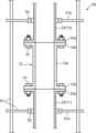
- FIG. 4 is a cross-sectional view showing the shape of a transparent tube and its mounting structure.
- FIG. 1 is a system diagram showing the overall configuration of a perlite filling device 1 as an example of a granular insulation material filling device.
- the perlite filling device 1 is a device for filling perlite P into an insulation space S1 in a multi-shell tank 100.
- the multi-shell tank 100 is a double-shelled spherical tank for storing low-temperature liquefied hydrogen, and includes a spherical tank inner tank 101 that defines a storage space S2 for liquefied hydrogen, a spherical tank outer tank 102 that accommodates the tank inner tank 101, and a support 103 that supports the tank outer tank 102 on the ground.
- the insulation space S1 is a space of a predetermined thickness formed between the tank inner tank 101 and the tank outer tank 102 for cold insulation.
- Perlite P is a granular (powdered) insulation material that is filled into the insulation space S1 to enhance the cold insulation effect.
- the perlite filling device 1 is prepared before the multi-shell tank 100 is put into operation, i.e., before liquefied hydrogen is stored in the storage space S2, and is used to fill the insulating space S1 with perlite P in a compressed state.
- the perlite filling device 1 includes a perlite container 2, a perlite introduction pipe 3, a vacuum pump 4, and a balance gas supply pipe 5.
- the perlite container 2 is a container that contains perlite P before it is filled into the insulating space S1.
- the perlite introduction pipe 3 is a pipe for introducing perlite P from the perlite container 2 to the insulating space S1, and connects the tank outer tank 102 and the perlite container 2 to each other.
- the vacuum pump 4 is a pump for vacuuming the insulating space S1, and is connected to the tank outer tank 102 via a suction pipe 41.
- the balance gas supply pipe 5 is a pipe for balancing the pressure between the storage space S2 and the perlite container 2, and connects the tank inner tank 101 and the perlite container 2 to each other.
- the perlite container 2 corresponds to the "storage container” in this disclosure
- the perlite introduction pipe 3 corresponds to the "introduction pipe” in this disclosure.
- the perlite container 2 is installed in a position somewhat distant from the multi-shell tank 100 while being suspended by a crane. That is, one end of a wire W extending from a crane is connected to the perlite container 2, and the perlite container 2 is lifted by the crane via the wire W, thereby installing the perlite container 2 in an inclined position relative to the ground. Specifically, the perlite container 2 is installed in an inclined position such that the height of the end closer to the multi-shell tank 100 is lower than the height of the opposite end. Note that in Figure 1, the perlite container 2 before being lifted by the crane is shown by a two-dot chain line.
- An outlet 2a is formed at one end of the perlite container 2 closer to the multi-shell tank 100, i.e., the end that is lower in height when tilted, for drawing out perlite P from the perlite container 2.
- a gas supply port 2b is formed at the other end of the perlite container 2 farther from the multi-shell tank 100, i.e., the end that is higher in height when tilted, for supplying balance gas into the perlite container 2.
- nitrogen gas present in the storage space S2 in the tank inner vessel 101 is supplied as the balance gas. Details will be described later.
- the perlite introduction pipe 3 includes an upstream pipe 11 connected to the outlet 2a of the perlite container 2, a downstream pipe 13 connected to the outer tank 102, and a transparent pipe 12 attached between the upstream pipe 11 and the downstream pipe 13.
- the upstream pipe 11 includes a horizontal pipe 21 that extends substantially horizontally from the outlet 2a of the perlite container 2 toward the multi-shell tank 100, and a vertical pipe 22 that extends in the up-down direction (vertical direction) and connects the downstream end of the horizontal pipe 21 to the transparent pipe 12.
- the vertical pipe 22 is a rigid pipe made of, for example, a steel pipe.
- the horizontal pipe 21 is a combination of a flexible pipe 21F and a rigid pipe.
- the flexible pipe 21F is a pipe that is flexible and can be bent freely, and is made of, for example, a well-known flexible steel pipe.
- the portion of the horizontal pipe 21 other than the flexible pipe 21F is made of a rigid pipe such as a steel pipe.
- the downstream pipe 13 includes a vertical pipe 23 extending upward from the transparent pipe 12, and a connecting pipe 24 connecting the downstream end (upper end) of the vertical pipe 23 to the tank outer tank 102.
- the vertical pipe 23 is made of a rigid pipe such as a steel pipe.
- the connecting pipe 24 includes at least a part of a flexible pipe 24F such as a flexible steel pipe.
- the downstream end of the connecting pipe 24 is connected to the filling port 102a of the tank outer tank 102.
- the filling port 102a is a communication part for introducing the perlite P supplied from the perlite introduction pipe 3 into the insulation space S1, and is provided at multiple locations on the tank outer tank 102.
- the connecting pipe 24 is selectively connected to one of the multiple filling ports 102a, and in that state, the perlite P is filled into the insulation space S1. In other words, the perlite P is filled while appropriately switching the filling port 102a to which the connecting pipe 24 is connected.
- the transparent tube 12 is a straight tube made of a transparent synthetic resin.
- the transparent tube 12 only needs to be transparent enough to allow the perlite P passing through it to be visible from the outside, and may be made of either a transparent or translucent material.
- the transparent tube 12 may be a transparent or translucent acrylic tube.
- the transparent tube 12 is attached between the upstream tube 11 and the downstream tube 13 in a vertical position with its axis extending in the vertical direction.
- FIG. 2 is a cross-sectional view showing the shape of the transparent tube 12 and its mounting structure.
- the transparent tube 12 includes a cylindrical straight portion 12a extending in the vertical direction, and a pair of flange portions 12b extending radially outward from both the upper and lower ends of the straight portion 12a.
- the straight portion 12a and the flange portions 12b are joined together, for example, via an adhesive.
- the upper flange portion 12b is joined to a flange 23a formed at the lower end of the vertical tube 23 of the downstream tube 13 via a fastening member 47 such as a bolt, and the lower flange portion 12b is joined to a flange 22a formed at the upper end of the vertical tube 22 of the upstream tube 11 via a fastening member 47.
- a fastening member 47 such as a bolt
- the transparent tube 12 is held between the upstream tube 11 and the downstream tube 13 in a vertical position so that it can be freely attached and detached.
- the transparent pipe 12 and the vertical pipes 22, 23 above and below it are supported by a scaffolding 50.
- the scaffolding 50 includes a frame body 51 consisting of a plurality of pipes arranged vertically and horizontally.
- the frame body 51 has a first horizontal frame 51a extending horizontally below the transparent pipe 12 and a second horizontal frame 51b extending horizontally above the transparent pipe 12.
- the first horizontal frame 51a is fixed to the vertical pipe 22 of the upstream pipe 11 via a fastener 52
- the second horizontal frame 51b is fixed to the vertical pipe 23 of the downstream pipe 13 via a fastener 52.
- the scaffolding 50 supports the vertical piping group including the transparent pipe 12 by fixing the vertical pipes 22, 23 above and below the transparent pipe 12 with the horizontal frames 51a, 51b. Since there is no frame that directly holds the transparent pipe 12, the frame does not get in the way when viewing the inside of the transparent pipe 12.
- a flow control valve 31 is provided in the upstream pipe 11 of the perlite introduction pipe 3.
- the flow control valve 31 is a valve that is opened and closed to adjust the flow rate of the perlite introduction pipe 3. Any type of flow control valve 31 can be used as long as it can adjust the flow rate of the perlite introduction pipe 3.
- the flow control valve 31 is attached to a position relatively close to the transparent pipe 12 in the upstream pipe 11. In other words, the flow control valve 31 is attached near the downstream end of the horizontal pipe 21 of the upstream pipe 11 so that the distance between the transparent pipe 12 and the flow control valve 31 is small.
- the distance between the flow control valve 31 and the transparent pipe 12 is set to a distance that allows the same operator to operate the flow control valve 31 while visually checking inside the transparent pipe 12.
- a flexible pipe 21F is attached between the flow control valve 31 and the transparent pipe 12.
- An on-off valve 32 is provided in the downstream pipe 13 of the perlite introduction pipe 3.
- the on-off valve 32 is a valve for switching between the introduction of perlite P into the insulating space S1 through the perlite introduction pipe 3 and its stop. That is, the on-off valve 32 is opened when the introduction of perlite P is started, and closed when the introduction of perlite P is stopped.
- the on-off valve 32 may be of any type as long as it can open or close the pipeline, but a ball valve that can be quickly shut off in the event of an unforeseen event is preferable.
- the on-off valve 32 is attached to a position close to the filling port 102a in the downstream pipe 13. Specifically, the on-off valve 32 is attached to a position between the flexible tube 24F of the connecting pipe 24 connected to the filling port 102a and the filling port 102a.
- the vacuum pump 4 is a suction pump that includes a pump element capable of sucking gas and a drive source such as an electric motor that drives the pump element.
- the vacuum pump 4 is in communication with the insulating space S1 of the multi-shell tank 100 via a suction pipe 41, and is capable of evacuating the insulating space S1 by sucking gas from the insulating space S1 through the suction pipe 41 and discharging it to the outside.
- a large pressure difference is generated between the perlite container 2 and the insulating space S1.
- the vacuum pump 4 is driven so as to generate such a pressure difference. As a result, perlite P is drawn into the insulating space S1 through the perlite introduction pipe 3.
- the balance gas supply pipe 5 is a pipe for supplying the gas present in the storage space S2 in the tank inner vessel 101 to the perlite container 2 as a balance gas, and connects the gas supply port 2b of the perlite container 2 to the tank inner vessel 101.
- the storage space S2 is filled with nitrogen gas, which is an inert gas, during the filling operation. That is, nitrogen gas is supplied from the gas source 60, which is a nitrogen gas supply source, to the storage space S2 through the supply pipe 61 at any time, so that the storage space S2 is constantly filled with nitrogen gas at a substantially constant pressure.
- the balance gas supply pipe 5 serves to maintain the pressure in the perlite container 2 at the same pressure as the storage space S2 by connecting the large-capacity storage space S2 filled with nitrogen gas and the perlite container 2 to each other in this way.
- the nitrogen gas supply pipe 61 is equipped with an on-off valve 62 such as a ball valve.
- the balance gas supply pipe 5 is provided with a first on-off valve 34, a second on-off valve 35, and a check valve 36.
- the first and second on-off valves 34, 35 are valves consisting of ball valves or the like that can open/close the pipe line, similar to the on-off valve 32 described above.
- the check valve 36 is a check valve that allows flow from the storage space S2 toward the perlite container 2 and prohibits flow in the opposite direction.
- the first on-off valve 34 is attached to the upstream end of the balance gas supply pipe 5 close to the multi-shell tank 100, and the second on-off valve 35 is attached to the downstream end of the balance gas supply pipe 5 close to the gas supply port 2b of the perlite container 2.
- the check valve 36 is attached near the downstream side of the first on-off valve 34.
- the perlite filling device 1 is first assembled. That is, the perlite container 2 is brought into a fixed position at a specified distance from the multi-shell tank 100, and the perlite introduction pipe 3 and the balance gas supply pipe 5 are assembled between the perlite container 2 and the multi-shell tank 100.
- a vacuum pump 4 is prepared, and the vacuum pump 4 is connected to the tank outer tank 102 via a suction pipe 41.
- the perlite container 2 is lifted by a crane so that the height of the end closer to the multi-shell tank 100 is relatively low.
- the perlite introduction pipe 3 is assembled to connect the outlet 2a of the perlite container 2 to the filling port 102a of the tank outer tank 102
- the balance gas supply pipe 5 is assembled to connect the gas supply port 2b of the perlite container 2 to the tank inner tank 101.
- the filling port 102a to which the perlite introduction pipe 3 is first connected is selected from among the multiple filling ports 102a provided in the tank outer tank 102 that are relatively low in height.
- the operation of filling the insulating space S1 with perlite P is started. That is, the on-off valves 32, 34, and 35 of the perlite introduction pipe 3 and the balance gas supply pipe 5 are opened, and in this state the vacuum pump 4 is driven to evacuate the insulating space S1. As a result, the perlite P in the perlite container 2 is drawn into the insulating space S1 through the perlite introduction pipe 3, and filling of the perlite P begins. Note that for a while after the start of filling of the perlite P, the flow rate control valve 31 of the perlite introduction pipe 3 is basically kept fully open.
- the perlite P flows vigorously inside the perlite introduction pipe 3.
- the worker can visually determine this through the transparent tube 12.
- the worker can determine the flow rate of the perlite P passing through the perlite introduction pipe 3 by visually inspecting the inside of the transparent tube 12. At this time, if the flow rate of the perlite P is sufficiently large, it can be determined that the filling of the perlite P is proceeding smoothly.
- the pressure difference between the perlite container 2 and the insulating space S1 may decrease or its fluctuation to increase, which may cause the flow of the perlite P to stagnate. If the flow of the perlite P stagnates, the flow rate of the perlite P introduced into the insulating space S1 decreases, and the efficiency of the filling operation decreases.
- the worker can confirm this by visual inspection through the transparent tube 12. That is, during the perlite P filling operation, the worker visually inspects the state of the perlite P passing through the transparent tube 12 as appropriate. Then, if the visual inspection confirms that the flow rate of the perlite P has decreased significantly, it is determined that the flow of the perlite P has stagnated.
- the worker will attempt to eliminate the stagnation by operating the flow control valve 31. For example, if the flow control valve 31 is fully open or close to fully open at the time the stagnation in the flow is confirmed, the worker will first perform a throttling operation to reduce the opening of the flow control valve 31. This will restore the pressure difference between the perlite container 2 and the insulated space S1, and may promote the flow of the perlite P. Alternatively, the worker can repeatedly reduce and increase the opening of the flow control valve 31 to find an appropriate opening that will promote the flow.
- the worker determines that it is better to change the filling port 102a used, and performs the work of replacing the downstream end of the perlite introduction pipe 3 with another filling port 102a. For example, the worker replaces the downstream end of the perlite introduction pipe 3 with another filling port 102a that is located higher than the filling port 102a that was used until now, or with another filling port 102a that is at the same height but in a different circumferential position.
- the work of filling the insulation space S1 with perlite P is performed in the same manner as described above. In this way, the work of filling the insulation space S1 with perlite P is performed while gradually increasing the height of the filling port 102a used. As a result, a sufficient amount of perlite P is filled in a compressed state in the insulation space S1.
- the transparent tube 12 is provided in the middle of the perlite introduction tube 3, so that the flow state of the perlite P flowing inside the transparent tube 12 can be visually confirmed when the perlite P is filled through the perlite introduction tube 3. If the stagnation of the flow of the perlite P is confirmed by the visual inspection, the flow stagnation can be eliminated by appropriately operating the flow control valve 31. Alternatively, if a situation in which the operation of the flow control valve 31 is not enough, for example, a situation in which the flow of the perlite P is substantially stopped (perlite P is clogged), is confirmed, the filling of the perlite P can be continued by taking another measure such as switching the filling port 102a to which the perlite introduction tube 3 is connected. Thus, according to this embodiment in which the flow state of the perlite P can be visually observed through the transparent tube 12, the perlite P can be efficiently filled into the insulation space S1, and the man-hours required for the filling can be reduced.
- the flow control valve 31 is provided near the upstream side of the transparent tube 12, so the same worker can operate the flow control valve 31 while visually checking the inside of the transparent tube 12. This makes it possible to quickly resolve stagnation in the flow of the perlite P.
- a flexible tube 21F made of a flexible steel pipe or the like is provided between the perlite container 2 and the transparent tube 12, so that the transmission of vibration from the perlite container 2 to the transparent tube 12 via the upstream tube 11 can be suppressed. That is, during the perlite P filling operation, the perlite container 2 lifted by the crane vibrates, and the vibration may be transmitted to the transparent tube 12 via the upstream tube 11.
- a part of the piping (upstream tube 11) between the perlite container 2 and the transparent tube 12 is made of a flexible tube 21F, so that the vibration is absorbed by the flexible tube 21F, and the vibration transmitted to the transparent tube 12 can be reduced. This ensures good visibility inside the transparent tube 12 and prevents damage to the transparent tube 12.
- a transparent tube 12 made of synthetic resin including a straight portion 12a and a flange portion 12b joined by an adhesive or the like is used, so suppressing vibration transmission using the flexible tube 21F described above is effective in protecting the transparent tube 12.
- this embodiment which can reduce vibration transmitted to the transparent tube 12, it is possible to prevent a situation in which cracks occur at the joint between the straight portion 12a and the flange portion 12b due to the vibration, and the transparent tube 12 can be appropriately protected.
- the transparency of the transparent tube 12 may decrease due to repeated sliding of the perlite P against the inner wall of the transparent tube 12.
- a synthetic resin tube having flange portions 12b on both ends is used as the transparent tube 12, so that the transparent tube 12 can be easily replaced according to the decrease in transparency, and visibility of the inside of the transparent tube 12 can be maintained.
- the target for filling the perlite P by the perlite filling device 1 is a multi-shell tank 100 (liquefied hydrogen tank) that stores liquefied hydrogen
- the target for filling the perlite by this device is not limited to liquefied hydrogen tanks, and may be tanks that store other types of liquefied gas.
- this device may be used to fill the insulated space of a multi-shell tank that stores liquefied natural gas (LNG), liquid helium, liquid nitrogen, liquefied ammonia, liquefied petroleum gas, etc. with perlite.
- LNG liquefied natural gas
- the insulating space S1 of the multi-shell tank 100 is filled with granular (powdered) perlite P, but the material filled into the insulating space S1 can be any granular material that exhibits insulating properties, that is, granular insulating material, and is not limited to perlite.
- glass particles known as glass bubbles may be used as granular insulating material.
- the granular insulation filling device is a device for filling an insulated space in a multi-shell tank that stores liquefied gas with granular insulation, and includes a storage container that stores the granular insulation, an introduction pipe that connects the storage container to the multi-shell tank and can introduce the granular insulation in the storage container into the insulated space, and a flow control valve that can adjust the flow rate of the introduction pipe.
- the introduction pipe includes a transparent pipe that is transparent enough to allow the granular insulation flowing inside to be visually observed.
- the flow control valve can be operated appropriately to eliminate the stagnation of the flow. This allows the granular insulation material to be filled efficiently into the insulated space, and reduces the amount of work required for filling.
- the flow rate control valve is provided near the upstream side of the transparent tube.
- the flow control valve located near the transparent tube can be used to eliminate the stagnation.
- the introduction pipe includes an upstream pipe that connects the transparent pipe and the storage container and is made of a flexible pipe, at least a portion of which is bendable.
- the transparent tube is a synthetic resin tube having flanges on both ends.
- the replacement when the transparent tube needs to be replaced, the replacement can be easily performed.
- Perlite filling equipment granular insulation material filling equipment
- Perlite container storage container
- Perlite inlet pipe inlet piping
- upstream pipe 12 transparent pipe
- 12b flange portion 21F flexible pipe 31 flow rate control valve
- multi-shell tank S1 thermal insulation space P perlite (granular insulation material)
Landscapes
- Engineering & Computer Science (AREA)
- Physics & Mathematics (AREA)
- Thermal Sciences (AREA)
- Mechanical Engineering (AREA)
- General Engineering & Computer Science (AREA)
- Filling Or Discharging Of Gas Storage Vessels (AREA)
Abstract
粒状断熱材充填装置(1)は、液化ガスを貯蔵する多重殻タンク100内の断熱空間S1に粒状断熱材(P)を充填する装置であって、粒状断熱材(P)を収容する収容容器(2)と、収容容器(2)と多重殻タンク100とを接続し、収容容器(2)内の粒状断熱材(P)を断熱空間S1に導入可能な導入配管(3)と、導入配管(3)の流量を調整可能な流量調整弁31とを備える。導入配管(3)は、内部を流れる粒状断熱材を目視できる程度の透明性を有する透明管12を含む。
Description
本開示は、液化ガスを貯蔵する多重殻タンク内の断熱空間に粒状断熱材を充填する装置に関する。
液化水素や液化天然ガス(LNG)などの低温の液化ガスは、一般に、多重殻タンクの内部に貯蔵される。多重殻タンクは、内槽と、内槽を収容する外槽とを含むタンクである。液化ガスの保冷のため、内槽と外槽との間には所定厚みの断熱空間が形成される。また、当該断熱空間にはパーライト等の粒状断熱材が充填される。
前記のような多重殻タンク内の断熱空間に粒状断熱材を充填する方法として、下記特許文献1に記載の工法が知られている。具体的に、この特許文献1に記載のパーライト充填工法は、パーライトを貯えるパーライトホッパと多重殻タンク(貯槽)とを配管で接続し、かつその状態で断熱空間内のガスを真空ポンプで吸引することにより、パーライトホッパ内にあるパーライトを前記配管を通じて断熱空間に充填するというものである。
前記特許文献1のように、パーライト等の粒状断熱材を配管を通じて多重殻タンクの断熱空間に充填する場合には、例えば充填作業の途中で配管内の圧力状態が変動する等により、当該配管内の粒状断熱材の流動が停滞することが起こり得る。粒状断熱材の流動が停滞すると、前記断熱空間に規定量の粒状断熱材を充填し終わるのに要する期間が延び、作業効率が悪化してしまう。
本開示は、前記のような事情に鑑みてなされたものであり、多重殻タンクの断熱空間に粒状断熱材を効率よく充填することが可能な粒状断熱材充填装置を提供することを目的とする。
前記課題を解決するためのものとして、本開示の一局面に係る粒状断熱材充填装置は、液化ガスを貯蔵する多重殻タンク内の断熱空間に粒状断熱材を充填する装置であって、前記粒状断熱材を収容する収容容器と、前記収容容器と前記多重殻タンクとを接続し、前記収容容器内の粒状断熱材を前記断熱空間に導入可能な導入配管と、前記導入配管の流量を調整可能な流量調整弁とを備え、前記導入配管は、内部を流れる粒状断熱材を目視できる程度の透明性を有する透明管を含むものである。
本開示の粒状断熱材充填装置によれば、多重殻タンクの断熱空間に粒状断熱材を効率よく充填することができる。
[パーライト充填装置の構成]
以下、図面に基づいて、本開示の粒状断熱材充填装置の一実施形態について説明する。図1は、粒状断熱材充填装置の一例としてのパーライト充填装置1の全体構成を示すシステム図である。パーライト充填装置1は、多重殻タンク100内の断熱空間S1にパーライトPを充填する装置である。本実施形態において、多重殻タンク100は、低温の液化水素を貯蔵するための二重殻の球形タンクであり、液化水素の貯蔵空間S2を画成する球状のタンク内槽101と、タンク内槽101を収容する球状のタンク外槽102と、タンク外槽102を地盤上に支持する支柱103とを備える。断熱空間S1は、保冷のためにタンク内槽101とタンク外槽102との間に形成された所定厚みの空間である。パーライトPは、保冷効果を高めるために断熱空間S1に充填される粒状(粉状)の断熱材である。パーライト充填装置1は、多重殻タンク100の運用前、つまり貯蔵空間S2に液化水素が貯蔵される前に用意され、パーライトPを断熱空間S1に圧密状態で充填する用途に供される。
以下、図面に基づいて、本開示の粒状断熱材充填装置の一実施形態について説明する。図1は、粒状断熱材充填装置の一例としてのパーライト充填装置1の全体構成を示すシステム図である。パーライト充填装置1は、多重殻タンク100内の断熱空間S1にパーライトPを充填する装置である。本実施形態において、多重殻タンク100は、低温の液化水素を貯蔵するための二重殻の球形タンクであり、液化水素の貯蔵空間S2を画成する球状のタンク内槽101と、タンク内槽101を収容する球状のタンク外槽102と、タンク外槽102を地盤上に支持する支柱103とを備える。断熱空間S1は、保冷のためにタンク内槽101とタンク外槽102との間に形成された所定厚みの空間である。パーライトPは、保冷効果を高めるために断熱空間S1に充填される粒状(粉状)の断熱材である。パーライト充填装置1は、多重殻タンク100の運用前、つまり貯蔵空間S2に液化水素が貯蔵される前に用意され、パーライトPを断熱空間S1に圧密状態で充填する用途に供される。
パーライト充填装置1は、パーライト容器2と、パーライト導入管3と、真空ポンプ4と、バランスガス供給管5とを備える。パーライト容器2は、断熱空間S1に充填される前のパーライトPを収容する容器である。パーライト導入管3は、パーライト容器2から断熱空間S1へとパーライトPを導入するための配管であり、タンク外槽102とパーライト容器2とを互いに接続している。真空ポンプ4は、断熱空間S1を真空引きするためのポンプであり、吸引管41を介してタンク外槽102に接続されている。バランスガス供給管5は、貯蔵空間S2とパーライト容器2との間で圧力バランスをとるための配管であり、タンク内槽101とパーライト容器2とを互いに接続している。なお、パーライト容器2は、本開示における「収容容器」に相当し、パーライト導入管3は、本開示における「導入配管」に相当する。
パーライト容器2は、多重殻タンク100から幾分離れた位置において、クレーンにより吊られた状態で設置されている。すなわち、パーライト容器2には、クレーンから延びるワイヤWの一端が接続されており、当該ワイヤWを介してパーライト容器2がクレーンにより吊り上げられることにより、地盤に対し傾斜した姿勢でパーライト容器2が設置される。具体的に、パーライト容器2は、多重殻タンク100に近い側の端部の高さが反対側の端部の高さよりも低くなるように傾斜した姿勢で設置される。なお、図1には、クレーンにより吊り上げられる前のパーライト容器2を二点鎖線で示している。
多重殻タンク100に近いパーライト容器2の一端部、つまり傾斜状態において高さが低くなる方の端部には、パーライト容器2からパーライトPを導出するための出口2aが形成されている。また、多重殻タンク100から遠いパーライト容器2の他端部、つまり傾斜状態において高さが高くなる方の端部には、パーライト容器2内にバランスガスを供給するためのガス供給口2bが形成されている。なお、本実施形態では、バランスガスとして、タンク内槽101内の貯蔵空間S2に存在する窒素ガスが供給される。詳細は後述する。
パーライト導入管3は、パーライト容器2の出口2aに接続された上流管11と、タンク外槽102に接続された下流管13と、上流管11と下流管13との間に取り付けられた透明管12とを含む。
上流管11は、パーライト容器2の出口2aから多重殻タンク100に向かって略水平に延びる横管21と、横管21の下流端と透明管12とを接続する上下方向(鉛直方向)に延びる縦管22とを含む。縦管22は、例えば鋼管等から構成された剛性管である。横管21は、可撓管21Fと剛性管とを組み合わせたものである。可撓管21Fは、屈曲自在な可撓性を有する管であり、例えば周知のフレキシブル鋼管等から構成されている。横管21における可撓管21F以外の部分は、鋼管等の剛性管から構成されている。
下流管13は、透明管12から上方に延びる縦管23と、縦管23の下流端(上端)とタンク外槽102とを接続する接続管24とを含む。縦管23は、鋼管等の剛性管から構成されている。接続管24は、少なくとも一部にフレキシブル鋼管等の可撓管24Fを含む。接続管24の下流端は、タンク外槽102の充填口102aに接続されている。充填口102aは、パーライト導入管3から供給されたパーライトPを断熱空間S1に導入するための連通部であって、タンク外槽102の複数箇所に設けられている。これら複数の充填口102aのいずれかに接続管24が選択的に接続され、その状態で断熱空間S1へのパーライトPの充填作業が行われる。言い換えると、パーライトPの充填作業は、接続管24が接続される充填口102aを適宜切り替えながら行われる。
透明管12は、透明性を有する合成樹脂製のストレート管である。透明管12は、その内部を通過するパーライトPを外部から視認し得る程度の透明性を有していればよく、透明又は半透明のいずれの材質から構成されていてもよい。例えば、透明管12は、透明又は半透明のアクリル管とすることができる。透明管12は、その軸心が上下方向に延びる縦置きの姿勢で上流管11と下流管13との間に取り付けられている。
図2は、透明管12の形状及びその取付構造を示す断面図である。本図に示すように、透明管12は、上下方向に延びる円筒状のストレート部12aと、ストレート部12aの上下両端から径方向外側に張り出す一対のフランジ部12bとを含む。ストレート部12a及びフランジ部12bは、例えば接着剤を介して一体に接合されている。上側のフランジ部12bは、下流管13の縦管23の下端に形成されたフランジ23aにボルト等の締結部材47を介して結合され、下側のフランジ部12bは、上流管11の縦管22の上端に形成されたフランジ22aに締結部材47を介して結合されている。これにより、上流管11と下流管13との間に透明管12が縦置きの姿勢で着脱自在に保持される。
透明管12及びその上下の縦管22,23は、足場50によって支持されている。足場50は、縦横に組まれた複数のパイプからなるフレーム体51を含む。フレーム体51は、透明管12の下方において水平方向に延びる第1横フレーム51aと、透明管12の上方において水平方向に延びる第2横フレーム51bとを有する。第1横フレーム51aは、上流管11の縦管22に固定具52を介して固定され、第2横フレーム51bは、下流管13の縦管23に固定具52を介して固定されている。言い換えると、足場50は、透明管12の上下の縦管22,23を横フレーム51a,51bで固定することにより、透明管12を含む上下方向の配管群を支持している。透明管12を直接保持するフレームが存在しないため、透明管12の内部視認の際にフレームが邪魔にならない。
図1に示すように、パーライト導入管3の上流管11の途中には、流量調整弁31が設けられている。流量調整弁31は、パーライト導入管3の流量を調整するために開閉操作されるバルブである。流量調整弁31は、パーライト導入管3の流量を調整できるものであればその種類を問わない。流量調整弁31は、上流管11の中でも透明管12に比較的近い位置に取り付けられている。すなわち、透明管12と流量調整弁31との距離が小さくなるように、上流管11の横管21における下流端の近傍に流量調整弁31が取り付けられている。流量調整弁31と透明管12との距離は、同一の作業者が透明管12内を目視しながら流量調整弁31を操作し得る程度の距離に設定されている。流量調整弁31と透明管12との間には、可撓管21Fが取り付けられている。
パーライト導入管3の下流管13の途中には、開閉弁32が設けられている。開閉弁32は、パーライト導入管3を通じた断熱空間S1へのパーライトPの導入およびその停止を切り替えるためのバルブである。すなわち、開閉弁32は、パーライトPの導入を開始する際に開弁され、パーライトPの導入を停止する際に閉弁される。開閉弁32は、管路を開放又は遮断できるものであればその種類を問わないが、例えば不測事態の際に迅速に遮断できるボール弁が好適である。開閉弁32は、下流管13の中でも充填口102aに近い位置に取り付けられている。具体的に、開閉弁32は、充填口102aに接続される接続管24のうち可撓管24Fと充填口102aとの間の位置に取り付けられている。
真空ポンプ4は、ガスを吸引可能なポンプ要素と当該ポンプ要素を駆動する電動モータ等の駆動源とを含む吸引ポンプである。真空ポンプ4は、吸引管41を介して多重殻タンク100の断熱空間S1と連通しており、当該断熱空間S1内のガスを吸引管41から吸引して外部に排出することにより、断熱空間S1を真空化することが可能である。断熱空間S1が真空化されると、パーライト容器2と断熱空間S1との間に大きな圧力差が生じる。断熱空間S1へのパーライトPの導入時には、このような圧力差が生じるように真空ポンプ4が駆動される。これにより、パーライト導入管3を通じてパーライトPが断熱空間S1に引き込まれる。
バランスガス供給管5は、タンク内槽101内の貯蔵空間S2に存在するガスをバランスガスとしてパーライト容器2に供給するための配管であり、パーライト容器2のガス供給口2bとタンク内槽101とを互いに接続している。ここで、本実施形態のように液化水素用の多重殻タンク100にパーライトPを充填する場合、その充填作業中、貯蔵空間S2は不活性ガスである窒素ガスで満たされる。すなわち、窒素ガスの供給源であるガス源60から供給管61を通じて貯蔵空間S2に窒素ガスが随時供給されることにより、略一定の圧力の窒素ガスで貯蔵空間S2が満たされた状態が定常的に得られるようになっている。バランスガス供給管5は、このように窒素ガスで満たされた大容量の貯蔵空間S2とパーライト容器2とを互いに連通することにより、パーライト容器2内の圧力を貯蔵空間S2と同等の圧力に維持する役割を果たす。これにより、パーライトPの充填中、パーライト容器2と断熱空間S1との圧力差が継続的に確保されて、断熱空間S1にパーライトPが充填され易くなる。窒素ガス用の供給管61には、ボール弁等からなる開閉弁62が設けられている。
バランスガス供給管5には、第1開閉弁34、第2開閉弁35、及びチャッキ弁36が設けられている。第1及び第2開閉弁34,35は、上述した開閉弁32と同様、管路の開放/遮断が可能なボール弁等からなるバルブである。チャッキ弁36は、貯蔵空間S2からパーライト容器2に向かう流れを許容しかつその逆方向の流れを禁止する逆流防止弁である。第1開閉弁34は、多重殻タンク100に近いバランスガス供給管5の上流端部に取り付けられ、第2開閉弁35は、パーライト容器2のガス供給口2bに近いバランスガス供給管5の下流端部に取り付けられている。チャッキ弁36は、第1開閉弁34の下流側の近傍に取り付けられている。
[パーライトの充填作業]
次に、以上のようなパーライト充填装置1を用いて多重殻タンク100の断熱空間S1にパーライトPを充填する作業の概略手順について説明する。なお、この作業が開始される前提として、多重殻タンク100の貯蔵空間S2は既に窒素ガスで満たされているものとする。すなわち、開閉弁62が事前に開かれて、ガス源60からの窒素ガスが供給管61を通じて貯蔵空間S2に供給されることにより、貯蔵空間S2内のガスが空気から窒素ガスへと置換される。パーライトPの充填作業が開始されるのは、このような窒素ガスへの置換作業が完了した後である。
次に、以上のようなパーライト充填装置1を用いて多重殻タンク100の断熱空間S1にパーライトPを充填する作業の概略手順について説明する。なお、この作業が開始される前提として、多重殻タンク100の貯蔵空間S2は既に窒素ガスで満たされているものとする。すなわち、開閉弁62が事前に開かれて、ガス源60からの窒素ガスが供給管61を通じて貯蔵空間S2に供給されることにより、貯蔵空間S2内のガスが空気から窒素ガスへと置換される。パーライトPの充填作業が開始されるのは、このような窒素ガスへの置換作業が完了した後である。
パーライトPの充填作業を開始するために、まずパーライト充填装置1が組み立てられる。すなわち、多重殻タンク100から規定の距離だけ離れた定位置にパーライト容器2が搬入されるとともに、パーライト容器2と多重殻タンク100との間でパーライト導入管3及びバランスガス供給管5が組み立てられる。併せて真空ポンプ4が用意されて、当該真空ポンプ4とタンク外槽102とが吸引管41を介して接続される。パーライト容器2は、多重殻タンク100に近い側の端部の高さが相対的に低くなるようにクレーンによって持ち上げられる。また、パーライト導入管3は、パーライト容器2の出口2aとタンク外槽102の充填口102aとを接続するように組み立てられ、バランスガス供給管5は、パーライト容器2のガス供給口2bとタンク内槽101とを接続するように組み立てられる。なお、パーライト導入管3が最初に接続される充填口102aとしては、タンク外槽102に備わる複数の充填口102aの中でも比較的高さの低いものが選ばれる。
以上のようなパーライト充填装置1の組立後、パーライトPを断熱空間S1に充填する作業が開始される。すなわち、パーライト導入管3及びバランスガス供給管5の各開閉弁32,34,35が開弁されるとともに、その状態で真空ポンプ4が駆動されて断熱空間S1が真空化される。これにより、パーライト容器2内のパーライトPがパーライト導入管3を通じて断熱空間S1に引き込まれ、パーライトPの充填が開始される。なお、このようなパーライトPの充填開始からしばらくの間、パーライト導入管3の流量調整弁31は基本的に全開に維持される。
パーライトPの充填がスムーズに進行しているとき、パーライトPはパーライト導入管3の内部を勢いよく流動する。作業者は、このことを透明管12を通じて目視で判断することができる。すなわち、作業者は、パーライト導入管3を通過するパーライトPの流量の大小を、透明管12の内部を目視することで判断することができる。このとき、パーライトPの流量が十分に大きければ、パーライトPの充填がスムーズに進行していると判断できる。
ここで、前記のようなパーライトPの充填作業中、何らかの要因でパーライト容器2と断熱空間S1との圧力差が減少するか又はその変動が増大し、それによってパーライトPの流動が停滞することがある。パーライトPの流動が停滞すると、断熱空間S1へと導入されるパーライトPの流量が低下し、充填作業の効率が低下する。作業者は、このことを透明管12を通じた目視によって確認することができる。すなわち、作業者は、パーライトPの充填作業中、透明管12を通過するパーライトPの状況を適宜目視する。そして、当該目視の結果パーライトPの流量が有意に低下していることが確認された場合に、パーライトPの流動が停滞していると判断する。
パーライトPの流動の停滞が確認された場合、作業者は、流量調整弁31を操作することで当該流動の停滞解消を試みる。例えば、流動の停滞が確認された時点での流量調整弁31の開度が全開もしくはこれに近い開度であった場合、作業者は、まず流量調整弁31の開度を低下させる絞り操作を行う。これにより、パーライト容器2と断熱空間S1との圧力差が回復し、パーライトPの流動が促進される可能性がある。あるいは、作業者は、流量調整弁31の開度の低下/増大を繰り返しながら、流動の促進につながる適当な開度を探ることも可能である。
前記のような流量調整弁31の操作によってパーライトPの流動が一時的に回復したとしても、同一の充填口102aを使用したままではパーライトPの充填はいずれ困難になる。例えば、現在使用中の充填口102aの高さを大きく上回るレベルまでパーライトPが充填されると、それ以上多くのパーライトPを充填することは困難になり、パーライトPの流動が実質的に停止する。作業者は、このような流動の停止、つまりパーライトPの詰まりを、やはり透明管12の内部を目視することで確認することができる。
前記のようなパーライトPの詰まりが確認された場合、作業者は、使用する充填口102aを変更した方がよいと判断し、パーライト導入管3の下流端を他の充填口102aに付け替える作業を行う。例えば、作業者は、パーライト導入管3の下流端を、これまで使用していた充填口102aよりも高い位置にある他の充填口102aか、同等の高さでかつ周方向の位置が異なる他の充填口102aに付け替える。付け替え後は、上述した手順と同様の手順により、断熱空間S1へのパーライトPの充填作業を行う。このように、断熱空間S1にパーライトPを充填する作業は、使用する充填口102aの高さを徐々に上げながら行われる。これにより、断熱空間S1に十分な量のパーライトPが圧密状態で充填される。
[作用効果]
以上説明したように、本実施形態では、パーライト導入管3の途中に透明管12が設けられるので、パーライト導入管3を通じたパーライトPの充填時に、透明管12の内部を流れるパーライトPの流動具合を目視で確認することができる。そして、当該目視によってパーライトPの流動の停滞が確認された場合には、流量調整弁31を適宜操作することにより、流動の停滞解消を図ることができる。あるいは、流量調整弁31の操作では間に合わないような状況、例えばパーライトPの流動が実質的に停止している(パーライトPが詰まっている)状況が確認された場合には、パーライト導入管3の接続先の充填口102aを切り替えるといった別の措置を採ることにより、パーライトPの充填を継続することができる。このように、透明管12を通じてパーライトPの流動具合を目視できる本実施形態によれば、パーライトPを断熱空間S1に効率よく充填することができ、当該充填にかかる工数を削減することができる。
以上説明したように、本実施形態では、パーライト導入管3の途中に透明管12が設けられるので、パーライト導入管3を通じたパーライトPの充填時に、透明管12の内部を流れるパーライトPの流動具合を目視で確認することができる。そして、当該目視によってパーライトPの流動の停滞が確認された場合には、流量調整弁31を適宜操作することにより、流動の停滞解消を図ることができる。あるいは、流量調整弁31の操作では間に合わないような状況、例えばパーライトPの流動が実質的に停止している(パーライトPが詰まっている)状況が確認された場合には、パーライト導入管3の接続先の充填口102aを切り替えるといった別の措置を採ることにより、パーライトPの充填を継続することができる。このように、透明管12を通じてパーライトPの流動具合を目視できる本実施形態によれば、パーライトPを断熱空間S1に効率よく充填することができ、当該充填にかかる工数を削減することができる。
また、本実施形態では、透明管12の上流側の近傍に流量調整弁31が設けられるので、同一の作業者が透明管12の内部を目視しながら流量調整弁31を操作することができる。これにより、パーライトPの流動が停滞しているときに、その解消を迅速に図ることができる。
また、本実施形態では、パーライト容器2と透明管12との間にフレキシブル鋼管等からなる可撓管21Fが設けられるので、パーライト容器2から上流管11を介して透明管12に振動が伝達されるのを抑制することができる。すなわち、パーライトPの充填作業中、クレーンにより吊り上げられたパーライト容器2が振動して、当該振動が上流管11を介して透明管12に伝達される可能性がある。これに対し、本実施形態では、パーライト容器2と透明管12との間の配管(上流管11)の一部が可撓管21Fとされるので、当該可撓管21Fで振動が吸収される結果、透明管12に伝達される振動を低減することができる。これにより、透明管12の内部の視認性を良好に確保できるとともに、透明管12に損傷等が生じるのを抑止することができる。
特に、本実施形態では、接着剤等により接合されたストレート部12a及びフランジ部12bを含む合成樹脂製の透明管12が用いられるので、上述した可撓管21Fを用いた振動伝達の抑制は、透明管12の保護に有効となる。すなわち、透明管12に伝達される振動を低減可能な本実施形態では、当該振動に起因してストレート部12aとフランジ部12bとの接合部に割れが生じるような事態を抑止でき、透明管12を適切に保護することができる。
ここで、透明管12が継続使用されると、透明管12の内壁に対するパーライトPの摺動が繰り返されることで、透明管12の透明度が低下する可能性がある。これに対し、本実施形態では、両端にフランジ部12bを有する合成樹脂管が透明管12として用いられるので、前記透明度の低下に応じて容易に透明管12を交換することができ、透明管12の内部の視認性を維持することができる。
[変形例]
以上、本開示の好ましい実施形態について説明したが、本開示はこれに限定されるわけではなく、例えば次のような変形が可能である。
以上、本開示の好ましい実施形態について説明したが、本開示はこれに限定されるわけではなく、例えば次のような変形が可能である。
前記実施形態では、パーライト充填装置1によるパーライトPの充填対象を、液化水素を貯蔵する多重殻タンク100(液化水素タンク)としたが、本装置によるパーライトの充填対象は液化水素タンクに限られず、他の種類の液化ガスを貯蔵するタンクであってもよい。例えば、液化天然ガス(LNG)、液体ヘリウム、液体窒素、液化アンモニア、又は液化石油ガス等を貯蔵する多重殻タンクの断熱空間にパーライトを充填するのに本装置を使用してもよい。一方、液化水素は最も低温であるため、このような液化水素を貯蔵する多重殻タンクを対象とする場合は、保冷性能を高めるために十分な量のパーライトを断熱空間に圧密状態で充填することが求められる。このため、本装置は、液化水素を貯留する多重殻タンクに最も好適に適用され得る。
前記実施形態では、多重殻タンク100の断熱空間S1に粒状(粉状)のパーライトPを充填したが、断熱空間S1に充填されるのは断熱機能を発揮する粒状物質、つまり粒状断熱材であればよく、パーライトに限られない。例えば、グラスバブルズなどと称されるガラス粒を粒状断熱材として用いてもよい。
[まとめ]
前記実施形態及びその変形例には、以下の開示が含まれる。
前記実施形態及びその変形例には、以下の開示が含まれる。
本開示の一局面に係る粒状断熱材充填装置は、液化ガスを貯蔵する多重殻タンク内の断熱空間に粒状断熱材を充填する装置であって、前記粒状断熱材を収容する収容容器と、前記収容容器と前記多重殻タンクとを接続し、前記収容容器内の粒状断熱材を前記断熱空間に導入可能な導入配管と、前記導入配管の流量を調整可能な流量調整弁とを備える。前記導入配管は、内部を流れる粒状断熱材を目視できる程度の透明性を有する透明管を含むものである。
本開示によれば、導入配管を通じた粒状断熱材の充填時に、透明管の内部を流れる粒状断熱材の流動具合を目視で確認することができる。そして、当該目視によって粒状断熱材の流動の停滞が確認された場合には、流量調整弁を適宜操作することにより、流動の停滞解消を図ることができる。これにより、粒状断熱材を断熱空間に効率よく充填することができ、当該充填にかかる工数を削減することができる。
好ましくは、前記流量調整弁は、前記透明管の上流側の近傍に設けられる。
この態様では、粒状断熱材の流動の停滞が透明管で確認された場合に、当該透明管の近くにある流量調整弁を用いて流動の停滞解消を図ることができる。
好ましくは、前記導入配管は、前記透明管と前記収容容器とを接続するとともに少なくとも一部が屈曲自在な可撓管からなる上流管を含む。
この態様では、例えば収容容器等で生じ得る振動が透明管に伝達されるのを抑制することができる。これにより、透明管の内部の視認性を良好に確保できるとともに、透明管に損傷等が生じるのを抑止することができる。
好ましくは、前記透明管は、両端にフランジ部を有する合成樹脂製の管である。
この態様では、透明管を交換する必要が生じたときに、その交換作業を容易に行うことができる。
1 パーライト充填装置(粒状断熱材充填装置)
2 パーライト容器(収容容器)
3 パーライト導入管(導入配管)
11 上流管
12 透明管
12b フランジ部
21F 可撓管
31 流量調整弁
100 多重殻タンク
S1 断熱空間
P パーライト(粒状断熱材)
2 パーライト容器(収容容器)
3 パーライト導入管(導入配管)
11 上流管
12 透明管
12b フランジ部
21F 可撓管
31 流量調整弁
100 多重殻タンク
S1 断熱空間
P パーライト(粒状断熱材)
Claims (4)
- 液化ガスを貯蔵する多重殻タンク内の断熱空間に粒状断熱材を充填する装置であって、
前記粒状断熱材を収容する収容容器と、
前記収容容器と前記多重殻タンクとを接続し、前記収容容器内の粒状断熱材を前記断熱空間に導入可能な導入配管と、
前記導入配管の流量を調整可能な流量調整弁とを備え、
前記導入配管は、内部を流れる粒状断熱材を目視できる程度の透明性を有する透明管を含む、粒状断熱材充填装置。 - 請求項1に記載の粒状断熱材充填装置において、
前記流量調整弁は、前記透明管の上流側の近傍に設けられる、粒状断熱材充填装置。 - 請求項1又は2に記載の粒状断熱材充填装置において、
前記導入配管は、前記透明管と前記収容容器とを接続するとともに少なくとも一部が屈曲自在な可撓管からなる上流管を含む、粒状断熱材充填装置。 - 請求項1又は2に記載の粒状断熱材充填装置において、
前記透明管は、両端にフランジ部を有する合成樹脂製の管である、粒状断熱材充填装置。
Applications Claiming Priority (2)
| Application Number | Priority Date | Filing Date | Title |
|---|---|---|---|
| JP2022178865A JP2024068426A (ja) | 2022-11-08 | 2022-11-08 | 粒状断熱材充填装置 |
| JP2022-178865 | 2022-11-08 |
Publications (1)
| Publication Number | Publication Date |
|---|---|
| WO2024101247A1 true WO2024101247A1 (ja) | 2024-05-16 |
Family
ID=91032916
Family Applications (1)
| Application Number | Title | Priority Date | Filing Date |
|---|---|---|---|
| PCT/JP2023/039489 Ceased WO2024101247A1 (ja) | 2022-11-08 | 2023-11-01 | 粒状断熱材充填装置 |
Country Status (3)
| Country | Link |
|---|---|
| JP (1) | JP2024068426A (ja) |
| TW (1) | TW202426807A (ja) |
| WO (1) | WO2024101247A1 (ja) |
Families Citing this family (2)
| Publication number | Priority date | Publication date | Assignee | Title |
|---|---|---|---|---|
| WO2026117070A1 (ko) * | 2024-11-29 | 2026-06-04 | 에이치디한국조선해양 주식회사 | 단열재 충전 시스템 및 단열재 충전 방법 |
| WO2026117075A1 (ko) * | 2024-11-29 | 2026-06-04 | 에이치디한국조선해양 주식회사 | 단열재 이송 시스템 및 단열재 이송 방법 |
Citations (3)
| Publication number | Priority date | Publication date | Assignee | Title |
|---|---|---|---|---|
| JPH0196593U (ja) * | 1987-12-17 | 1989-06-27 | ||
| JPH02256999A (ja) * | 1989-03-30 | 1990-10-17 | Kawasaki Heavy Ind Ltd | パーライト真空断熱二重殻貯槽におけるパーライト充填工法 |
| JPH0811804A (ja) * | 1994-07-01 | 1996-01-16 | Iwatani Internatl Corp | 液化ガス貯蔵槽への粉末断熱材の自動充填方法 |
-
2022
- 2022-11-08 JP JP2022178865A patent/JP2024068426A/ja active Pending
-
2023
- 2023-11-01 WO PCT/JP2023/039489 patent/WO2024101247A1/ja not_active Ceased
- 2023-11-02 TW TW112142253A patent/TW202426807A/zh unknown
Patent Citations (3)
| Publication number | Priority date | Publication date | Assignee | Title |
|---|---|---|---|---|
| JPH0196593U (ja) * | 1987-12-17 | 1989-06-27 | ||
| JPH02256999A (ja) * | 1989-03-30 | 1990-10-17 | Kawasaki Heavy Ind Ltd | パーライト真空断熱二重殻貯槽におけるパーライト充填工法 |
| JPH0811804A (ja) * | 1994-07-01 | 1996-01-16 | Iwatani Internatl Corp | 液化ガス貯蔵槽への粉末断熱材の自動充填方法 |
Also Published As
| Publication number | Publication date |
|---|---|
| JP2024068426A (ja) | 2024-05-20 |
| TW202426807A (zh) | 2024-07-01 |
Similar Documents
| Publication | Publication Date | Title |
|---|---|---|
| JP2024068426A (ja) | 粒状断熱材充填装置 | |
| JP5560139B2 (ja) | ガス分配アセンブリ及びガス分配アセンブリを運転する方法 | |
| JP4955890B2 (ja) | 内部に配置され、外部で調節可能な調整器組立体を備える分配システム | |
| CN110185920B (zh) | 包括用于容纳泵组件的贮存器的低温储存容器 | |
| JP2018522167A (ja) | ガスキャビネット | |
| US12163611B2 (en) | Bayonet for LH2 offloading | |
| JP2005521846A (ja) | 低温液体の貯蔵タンク | |
| WO2024101235A1 (ja) | 粒状断熱材充填装置および方法 | |
| CN103518094A (zh) | 液化气出口系统、用于存储液化气的罐、重建液化气罐的方法以及建造液化气罐的方法 | |
| CN106439484B (zh) | 低温船用双管装卸臂 | |
| JP7579702B2 (ja) | 液体水素用の可搬型荷役設備 | |
| JP2002372197A (ja) | 気体貯蔵システム | |
| CN102748561A (zh) | 一种管路保温装置 | |
| US20220136783A1 (en) | Subcooler for carbon dioxide distribution systems | |
| JPH08200274A (ja) | 低温液化ガス用ポンプ | |
| CN212338902U (zh) | 一种低温槽车装卸车泵橇装置 | |
| JP2008509356A (ja) | 流体の貯蔵および送達デバイス | |
| CN212178231U (zh) | 一种管路减振器 | |
| CN218455065U (zh) | 一种可减振减压的管道输送系统 | |
| AU2017339047A1 (en) | Methods and system for filling a suppressant container | |
| JP7012189B1 (ja) | ガス供給方法 | |
| JP2715271B2 (ja) | 液化ガス充填容器の検査方法 | |
| JP7774982B2 (ja) | 真空排気装置 | |
| CN223330736U (zh) | 一种空压系统密封组件 | |
| CN220668763U (zh) | 一种海底输送管道水锤抗振装置 |
Legal Events
| Date | Code | Title | Description |
|---|---|---|---|
| 121 | Ep: the epo has been informed by wipo that ep was designated in this application |
Ref document number: 23888595 Country of ref document: EP Kind code of ref document: A1 |
|
| NENP | Non-entry into the national phase |
Ref country code: DE |
|
| 122 | Ep: pct application non-entry in european phase |
Ref document number: 23888595 Country of ref document: EP Kind code of ref document: A1 |