WO2024101142A1 - 管継手部材 - Google Patents
管継手部材 Download PDFInfo
- Publication number
- WO2024101142A1 WO2024101142A1 PCT/JP2023/038295 JP2023038295W WO2024101142A1 WO 2024101142 A1 WO2024101142 A1 WO 2024101142A1 JP 2023038295 W JP2023038295 W JP 2023038295W WO 2024101142 A1 WO2024101142 A1 WO 2024101142A1
- Authority
- WO
- WIPO (PCT)
- Prior art keywords
- pipe coupling
- flow path
- slide member
- slide
- coupling member
- Prior art date
- Legal status (The legal status is an assumption and is not a legal conclusion. Google has not performed a legal analysis and makes no representation as to the accuracy of the status listed.)
- Ceased
Links
Images


Classifications
-
- F—MECHANICAL ENGINEERING; LIGHTING; HEATING; WEAPONS; BLASTING
- F16—ENGINEERING ELEMENTS AND UNITS; GENERAL MEASURES FOR PRODUCING AND MAINTAINING EFFECTIVE FUNCTIONING OF MACHINES OR INSTALLATIONS; THERMAL INSULATION IN GENERAL
- F16L—PIPES; JOINTS OR FITTINGS FOR PIPES; SUPPORTS FOR PIPES, CABLES OR PROTECTIVE TUBING; MEANS FOR THERMAL INSULATION IN GENERAL
- F16L37/00—Couplings of the quick-acting type
- F16L37/28—Couplings of the quick-acting type with fluid cut-off means
- F16L37/38—Couplings of the quick-acting type with fluid cut-off means with fluid cut-off means in only one of two pipe-end fittings
- F16L37/40—Couplings of the quick-acting type with fluid cut-off means with fluid cut-off means in only one of two pipe-end fittings with a lift valve being opened automatically when the coupling is applied
-
- F—MECHANICAL ENGINEERING; LIGHTING; HEATING; WEAPONS; BLASTING
- F16—ENGINEERING ELEMENTS AND UNITS; GENERAL MEASURES FOR PRODUCING AND MAINTAINING EFFECTIVE FUNCTIONING OF MACHINES OR INSTALLATIONS; THERMAL INSULATION IN GENERAL
- F16L—PIPES; JOINTS OR FITTINGS FOR PIPES; SUPPORTS FOR PIPES, CABLES OR PROTECTIVE TUBING; MEANS FOR THERMAL INSULATION IN GENERAL
- F16L37/00—Couplings of the quick-acting type
- F16L37/22—Couplings of the quick-acting type in which the connection is maintained by means of balls, rollers or helical springs under radial pressure between the parts
- F16L37/23—Couplings of the quick-acting type in which the connection is maintained by means of balls, rollers or helical springs under radial pressure between the parts by means of balls
Definitions
- the present invention relates to a pipe coupling member that is detachably connected to a corresponding pipe coupling member, and in particular to a pipe coupling member that is designed to prevent the corresponding pipe coupling member from being connected when fluid pressure is applied to the pipe coupling member.
- the valve member built into the pipe coupling member is prevented from displacing to the open position, and the holding member for holding the locking member for connecting and holding the corresponding pipe coupling member in the locked position is not operated.
- the holding member does not operate, so the operator can recognize that the pipe coupling member is under fluid pressure.
- the conventional pipe coupling members described above make it possible to prevent the corresponding pipe coupling member from being connected when fluid pressure is applied to the pipe coupling member.
- the operator may think that the pressing member is not moving properly because the pressing member does not operate, and may try to forcibly operate the pressing member.
- the operator may think that the corresponding pipe coupling member has not been inserted sufficiently and may try to forcibly insert the corresponding pipe coupling member. Such forcible operation may damage the pipe coupling member or injure the operator.
- the present invention aims to provide a pipe coupling member that allows an operator to more reliably recognize that fluid pressure is being applied to a pipe coupling member when attempting to connect a corresponding pipe coupling member while fluid pressure is being applied to the pipe coupling member.
- a pipe coupling member that is detachably connected to a corresponding pipe coupling member, a fitting body including a tubular portion having a front end opening, a rear end opening, and an internal space extending between the front end opening and the rear end opening, and an inner extension portion extending from an inner circumferential surface of the tubular portion within the internal space; a coupling locking member attached to the coupling body, the coupling locking member being displaceable between a coupling position where the coupling locking member engages with a corresponding pipe coupling member inserted from the front end opening to a predetermined position within the internal space to couple the corresponding pipe coupling member to the corresponding pipe coupling member, and a coupling release position where the coupling locking member disengages from the corresponding pipe coupling member to release the connection between the corresponding pipe coupling member and the corresponding pipe coupling member; a first slide member disposed within the internal space and configured to be pushed by the corresponding pipe coupling member and displaced from a front position to a
- this pipe coupling member When this pipe coupling member receives fluid pressure from the rear end opening while the corresponding pipe coupling member is not connected, the second slide member is displaced to a forward position, thereby holding the first locking element in a displacement prevention position. As a result, the first slide member is prevented from displacing from the forward position to the rear position. Therefore, even if an attempt is made to insert a corresponding pipe coupling member into this pipe coupling member, it will hit the first slide member and will not be able to be inserted to the specified position where connection is completed. Since the corresponding pipe coupling member cannot be inserted to the specified position, the operator can easily recognize that fluid pressure is already being applied to the pipe coupling member.
- the inner extension portion extends forward from an inner circumferential surface of the tubular portion to define a slide receiving space between the inner extension portion and the inner circumferential surface, the first slide member is at least partially located within the slide receiving space; the second slide member being at least partially located radially inward of the inner extension;
- the first locking element may be configured to protrude radially outward from the inner extending portion at the displacement prevention position and engage with the first slide member.
- a sleeve disposed on an outer circumferential surface of the joint body and displaceable between a locked position that holds the connection locking member in the connection position and an unlocked position that allows the connection locking member to be displaced to the disconnected position; a second locking element disposed in a locking element holding hole formed in the tubular portion, the second locking element being displaceable between a holding position where the second locking element engages with the sleeve to hold the sleeve in the disconnected position and a holding release position where the second locking element allows the sleeve to move from the disconnected position to the locked position; Further comprising: When the first slide member is in the forward position, the second locking element is held in the holding position by the first slide member, When the first slide member is in the rear position, the second locking element can be displaced to the retention release position.
- a flow path forming member that is disposed within the internal space, the flow path forming member having a front end side connection portion connected to a corresponding pipe coupling member inserted into the internal space, a rear end side valve pressing portion, and a first flow path portion extending rearward from the connection portion, the flow path forming member being displaced from a front position to a rear position when the corresponding pipe coupling member is inserted to the predetermined position; a valve member disposed behind the flow path component; A spring that biases the valve member forward; Further comprising: The second slide member has a second flow path portion extending in the front-rear direction and communicating with the first flow path portion, the valve member is displaceable with respect to the second slide member between a closing position where the valve member is pressed against the second slide member by the spring to close the second flow path portion and an opening position where the valve member is displaced rearward relative to the second slide member to open the second flow path portion, When the flow path forming member is in the forward position, the valve member moves forward together with
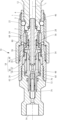
- FIG. 2 is a cross-sectional view of a female pipe coupling member according to one embodiment of the present invention.
- 2 is a cross-sectional view showing a state in which a corresponding male pipe coupling member is connected to the female pipe coupling member of FIG. 1 .
- 2 is a cross-sectional view showing a state in which a fluid pressure is applied to the female pipe coupling member of FIG. 1 when the female pipe coupling member is connected to a corresponding male pipe coupling member;
- FIG. FIG. 2 is a cross-sectional view showing a state in which a fluid pressure is applied to the female pipe coupling member of FIG. 1 before the male pipe coupling member is connected thereto;
- the female pipe fitting member (pipe fitting member) 10 is a pipe fitting member that is detachably connected to a corresponding male pipe fitting member (corresponding pipe fitting member) 1, as shown in Figures 1 to 3.
- the female pipe fitting member 10 comprises a fitting body 18 having an internal space 16 extending along a longitudinal axis L from a front end opening 12 to a rear end opening 14, and a connecting locking member 22 disposed within a locking member retaining hole 20 formed in the fitting body 18.
- the female pipe fitting member 10 further comprises a first slide member 24, a second slide member 26, and a flow path forming member 28, each of which is disposed within the internal space 16.
- the joint body 18 is composed of a front tubular member 32 and a rear tubular member 34 that are screwed together to form a tubular portion 30 that defines the internal space 16, and an intermediate member 36 that is sandwiched and held between the front tubular member 32 and the rear tubular member 34 within the internal space 16.
- the intermediate member 36 constitutes an inner extension portion 38 that extends forward from the inner peripheral surface 30a of the tubular portion 30, and a slide accommodation space 40 is defined between the inner peripheral surface 30a of the tubular portion 30 and the outer surface 38a of the inner extension portion 38.
- the front end opening 12 of the joint body 18 is adapted to receive a corresponding male pipe joint member 1.
- the rear end opening 14 is formed with a female thread portion 41 for connection to a fluid supply source (not shown).
- the first slide member 24 has a cylindrical shape, a portion of which is located within the slide accommodation space 40, and its front end 42 is arranged to be located in front of the slide accommodation space 40.
- the first slide member 24 is also displaceable back and forth in the direction of the longitudinal axis L between a forward position (FIGS. 1 and 4) and a rear position (FIGS. 2 and 3), and is biased forward by a spring 43 arranged between the first slide member 24 and the inner extension 38 of the coupling body 18.
- a spring 43 arranged between the first slide member 24 and the inner extension 38 of the coupling body 18.
- the flow path forming member 28 has a connecting portion 46 at the front end side that is connected to the corresponding male pipe coupling member 1, a valve pressing portion 48 that extends rearward in an elongated manner at the rear end side, and a first flow path portion 54 that extends rearward from a front flow path opening 50 of the connecting portion 46 to a rear flow path opening 52 generally along the longitudinal axis L.
- the flow path forming member 28 is displaceable back and forth in the direction of the longitudinal axis L between a forward position (FIGS. 1 and 4) and a rear position (FIGS. 2 and 3), and is biased forward by a spring 56 that is disposed between the flow path forming member 28 and the inner extension portion 38 of the coupling body 18.
- a stop ring 58 attached to its outer circumferential surface 28a engages with the inner extension portion 38 to prevent further forward displacement.
- the second slide member 26 has a second flow passage portion 60 that extends in the front-rear direction and communicates with the first flow passage portion 54 of the flow passage component 28.
- the second slide member 26 is displaceable in the front-rear direction in the direction of the longitudinal axis L between the rear position (FIGS. 1 and 2) and the front position (FIGS. 3 and 4), and is biased rearward by a spring 62 disposed between the second slide member 26 and the inner extension portion 38 in the joint body 18.
- the second slide member 26 is sealed between the inner peripheral surface 30a of the joint body 18 by a first seal member 64 attached to the joint body 18, and is sealed between the outer peripheral surface 28a of the flow passage component 28 by a second seal member 66 attached to the second slide member 26.
- the connecting locking member 22 is disposed within the locking member retaining hole 20 formed in the joint body 18 so as to be displaceable radially between a connecting position (FIGS. 1, 2, 3) and a disconnecting position (FIG. 4).
- the female pipe joint member 10 further includes a sleeve 68 disposed on the outer circumferential surface 18a of the joint body 18.
- the sleeve 68 is disposed so as to be displaceable back and forth in the direction of the longitudinal axis L between a locked position (FIGS. 2, 3) that holds the connecting locking member 22 in the connecting position and an unlocked position (FIGS. 1, 4) that allows the connecting locking member 22 to be displaced to the disconnecting position.
- the sleeve 68 is biased forward toward the locked position by a spring 70 disposed between the sleeve 68 and the joint body 18.
- the female pipe fitting member 10 further includes a valve member 72 disposed in the second flow path portion 60 of the second slide member 26.
- the valve member 72 is biased forward by a spring 74 disposed between the valve member 72 and the fitting body 18, and is pressed against a valve seat portion 76 formed in the second flow path portion 60.
- the second flow path portion 60 is closed by the valve member 72 being pressed against the valve seat portion 76.
- the female pipe joint member 10 further includes a first locking element 78 disposed in the inner extension portion 38 of the joint body 18, and a second locking element 80 disposed in the tubular portion 30.
- the first locking element 78 is displaceable in a first locking element retaining hole 82 formed in the inner extension portion 38 between a displacement-permitting position (FIGS. 1 and 2) protruding radially inward from the inner surface 38b of the inner extension portion 38 and a displacement-preventing position (FIGS. 3 and 4) protruding radially outward from the outer surface 38a of the inner extension portion 38.
- the second locking element 80 is displaceable in a second locking element retaining hole 84 formed in the tubular portion 30 between a retaining position (FIGS.
- the first slide member 24 In the state shown in FIG. 1, in which the male pipe coupling member 1 is not connected to the female pipe coupling member 10 and no fluid pressure is applied from the rear end opening 14, the first slide member 24 is in the forward position, whereby the second locking member 80 is held in the holding position by the first slide member 24.
- the second locking member 80 held in the holding position engages with the locking groove of the sleeve 68 to hold the sleeve 68 in the disconnected position.
- the second slide member 26 is in the rear position, whereby the first locking member 78 is freely displaceable between a radially outer displacement prevention position and a radially inner displacement allowance position.
- the front end surface 2 of the male pipe coupling member 1 first pushes the first slide member 24 backward, and then pushes the flow path component member 28 backward.
- the second locking member 80 is displaced radially inward by the sleeve 68, which is biased forward by the spring 70, to the release position.
- the sleeve 68 is displaced further forward by the spring 70, which displaces the connecting locking member 22 radially inward to the connecting position.
- the connecting locking member 22 in the connecting position engages with the locking groove 3 of the male pipe coupling member 1 to connect the male pipe coupling member 1 to the female pipe coupling member 10.
- the connecting locking member 22 is supported from the radial outside by the sleeve 68 in the locked position, and is held in the connecting position.
- the flow path component 28 has its connection portion 46 inserted into the flow path 4 of the male pipe coupling member 1 and is connected, and is pushed to a rear position by the front end surface 2 of the male pipe coupling member 1.
- the second slide member 26 when fluid is supplied from the fluid supply source connected to the rear end opening 14 and fluid pressure is applied from the rear end opening 14 side, the second slide member 26 is displaced to a forward position by the fluid pressure as shown in FIG. 3.
- the valve member 72 arranged in the second flow path section 60 of the second slide member 26 is initially displaced forward together with the second slide member 26, but is prevented from moving forward by abutting against the valve pressing portion 48 of the flow path forming member 28 along the way.
- valve member 72 is pressed against the valve seat portion 76 of the second slide member 26 until it abuts against the valve pressing portion 48, remaining in the closed position that closes the second flow path section 60, but as the second slide member 26 displaces to the forward position, it abuts against the valve pressing portion 48 and is prevented from moving forward, displacing backward relative to the second slide member 26 to the open position that opens the second flow path section 60.
- the valve member 72 is in the open position, the flow path from the rear end opening 14 to the forward flow path opening 50 of the flow path component 28 is connected, and the fluid supplied from the fluid supply source passes through the female pipe fitting member 10 and is supplied to the male pipe fitting member 1.
- the male pipe coupling member 1 cannot be inserted to the specified position because it engages with the first slide member 24 held in the forward position. Since the male pipe coupling member 1 cannot be inserted to the specified position, the operator can easily recognize that the female pipe coupling member 10 is already under fluid pressure and cannot be connected.
- the connecting locking member, the first locking element, and the second locking element are spherical members, but they can also be other shapes.
- the connecting locking member can be a chuck-shaped member that swings between a connecting position and a disconnecting position.
- the inner extension part of the joint body can extend rearward from the inner peripheral surface of the tubular part, a part of the first slide member is located radially inside the inner extension part, and a part of the second slide member is located radially outside the inner extension part.
- the first locking element can be configured to protrude radially inward from the inner extension part at the displacement prevention position and engage with the first slide member, and then displace radially outward from there to the displacement allowance position.
- terms indicating directions such as “front”, “rear”, “forward”, and “rear” in the present invention and the above embodiment are used simply to indicate the relative positional relationship in the configuration of the invention, and do not necessarily mean the direction in the actual installation state or usage state.
Landscapes
- Engineering & Computer Science (AREA)
- General Engineering & Computer Science (AREA)
- Mechanical Engineering (AREA)
- Quick-Acting Or Multi-Walled Pipe Joints (AREA)
Priority Applications (2)
| Application Number | Priority Date | Filing Date | Title |
|---|---|---|---|
| JP2024557297A JP7833048B2 (ja) | 2022-11-08 | 2023-10-24 | 管継手部材 |
| DE112023004736.7T DE112023004736T5 (de) | 2022-11-08 | 2023-10-24 | Rohrverbindungselement |
Applications Claiming Priority (2)
| Application Number | Priority Date | Filing Date | Title |
|---|---|---|---|
| JP2022-178835 | 2022-11-08 | ||
| JP2022178835 | 2022-11-08 |
Publications (1)
| Publication Number | Publication Date |
|---|---|
| WO2024101142A1 true WO2024101142A1 (ja) | 2024-05-16 |
Family
ID=91032647
Family Applications (1)
| Application Number | Title | Priority Date | Filing Date |
|---|---|---|---|
| PCT/JP2023/038295 Ceased WO2024101142A1 (ja) | 2022-11-08 | 2023-10-24 | 管継手部材 |
Country Status (3)
| Country | Link |
|---|---|
| JP (1) | JP7833048B2 (https=) |
| DE (1) | DE112023004736T5 (https=) |
| WO (1) | WO2024101142A1 (https=) |
Citations (4)
| Publication number | Priority date | Publication date | Assignee | Title |
|---|---|---|---|---|
| JPS4934020A (https=) * | 1972-08-02 | 1974-03-29 | ||
| JPH06109188A (ja) * | 1991-12-29 | 1994-04-19 | Toyota Motor Corp | クイックカップリング |
| JPH07233891A (ja) * | 1994-02-21 | 1995-09-05 | Betsuseru Kogyo:Kk | 流体流通用継手 |
| US20180100613A1 (en) * | 2016-10-06 | 2018-04-12 | Staubli Faverges | Quick coupling |
-
2023
- 2023-10-24 JP JP2024557297A patent/JP7833048B2/ja active Active
- 2023-10-24 DE DE112023004736.7T patent/DE112023004736T5/de active Pending
- 2023-10-24 WO PCT/JP2023/038295 patent/WO2024101142A1/ja not_active Ceased
Patent Citations (4)
| Publication number | Priority date | Publication date | Assignee | Title |
|---|---|---|---|---|
| JPS4934020A (https=) * | 1972-08-02 | 1974-03-29 | ||
| JPH06109188A (ja) * | 1991-12-29 | 1994-04-19 | Toyota Motor Corp | クイックカップリング |
| JPH07233891A (ja) * | 1994-02-21 | 1995-09-05 | Betsuseru Kogyo:Kk | 流体流通用継手 |
| US20180100613A1 (en) * | 2016-10-06 | 2018-04-12 | Staubli Faverges | Quick coupling |
Also Published As
| Publication number | Publication date |
|---|---|
| JPWO2024101142A1 (https=) | 2024-05-16 |
| JP7833048B2 (ja) | 2026-03-18 |
| DE112023004736T5 (de) | 2025-08-21 |
Similar Documents
| Publication | Publication Date | Title |
|---|---|---|
| US10663099B2 (en) | Pipe coupling comprising female coupling member and male coupling member | |
| US8469406B2 (en) | Socket for pipe joint and pipe joint | |
| US8256803B2 (en) | Socket for pipe joint and pipe joint | |
| US6237631B1 (en) | Low spill quick disconnect coupling | |
| US8186649B2 (en) | Female coupling member and male coupling member | |
| US4007909A (en) | Full flow valved fitting | |
| US7731243B2 (en) | Coupling element for removably joining pipes | |
| EP3171067B1 (en) | Non-spill connect under pressure coupler | |
| US9939096B2 (en) | Female element and coupling intended to form the disconnectable connection of two fluid pipe lines | |
| JP2018054124A (ja) | 継手及びこのような継手と組み合わされるサイクル車用の油圧ブレーキ回路 | |
| US10724666B2 (en) | Coupling member | |
| US5255699A (en) | Nipple with integral crossbar actuator and check valve | |
| JPH0830550B2 (ja) | 急速遮断雌型継手 | |
| US6050298A (en) | Safety circuit breaker for pressurized-fluid handling installation | |
| JP4348589B2 (ja) | 安全離脱装置付き連結具 | |
| US7537246B2 (en) | Pipe coupler | |
| WO2024101142A1 (ja) | 管継手部材 | |
| WO2012066588A1 (ja) | カプラ | |
| JP3526739B2 (ja) | 管継手 | |
| US5310161A (en) | High pressure gas line breakaway connector | |
| JPWO2024101142A5 (https=) | ||
| GB2585950A (en) | Safety connector | |
| KR20100038834A (ko) | 유증기 회수로가 구비된 주유기용 안전밸브 |
Legal Events
| Date | Code | Title | Description |
|---|---|---|---|
| 121 | Ep: the epo has been informed by wipo that ep was designated in this application |
Ref document number: 23888492 Country of ref document: EP Kind code of ref document: A1 |
|
| WWE | Wipo information: entry into national phase |
Ref document number: 2024557297 Country of ref document: JP |
|
| WWE | Wipo information: entry into national phase |
Ref document number: 112023004736 Country of ref document: DE |
|
| WWP | Wipo information: published in national office |
Ref document number: 112023004736 Country of ref document: DE |
|
| 122 | Ep: pct application non-entry in european phase |
Ref document number: 23888492 Country of ref document: EP Kind code of ref document: A1 |