WO2024101142A1 - Pipe joint member - Google Patents
Pipe joint member Download PDFInfo
- Publication number
- WO2024101142A1 WO2024101142A1 PCT/JP2023/038295 JP2023038295W WO2024101142A1 WO 2024101142 A1 WO2024101142 A1 WO 2024101142A1 JP 2023038295 W JP2023038295 W JP 2023038295W WO 2024101142 A1 WO2024101142 A1 WO 2024101142A1
- Authority
- WO
- WIPO (PCT)
- Prior art keywords
- pipe coupling
- flow path
- slide member
- slide
- coupling member
- Prior art date
Links
- 239000012530 fluid Substances 0.000 claims abstract description 38
- 230000008878 coupling Effects 0.000 claims description 107
- 238000010168 coupling process Methods 0.000 claims description 107
- 238000005859 coupling reaction Methods 0.000 claims description 107
- 238000006073 displacement reaction Methods 0.000 claims description 16
- 230000002265 prevention Effects 0.000 claims description 8
- 230000014759 maintenance of location Effects 0.000 claims description 2
- 230000002093 peripheral effect Effects 0.000 description 9
- 230000004308 accommodation Effects 0.000 description 4
- UFHFLCQGNIYNRP-UHFFFAOYSA-N Hydrogen Chemical compound [H][H] UFHFLCQGNIYNRP-UHFFFAOYSA-N 0.000 description 1
- 239000000446 fuel Substances 0.000 description 1
- 238000009434 installation Methods 0.000 description 1
Images


Definitions
- the present invention relates to a pipe coupling member that is detachably connected to a corresponding pipe coupling member, and in particular to a pipe coupling member that is designed to prevent the corresponding pipe coupling member from being connected when fluid pressure is applied to the pipe coupling member.
- the valve member built into the pipe coupling member is prevented from displacing to the open position, and the holding member for holding the locking member for connecting and holding the corresponding pipe coupling member in the locked position is not operated.
- the holding member does not operate, so the operator can recognize that the pipe coupling member is under fluid pressure.
- the conventional pipe coupling members described above make it possible to prevent the corresponding pipe coupling member from being connected when fluid pressure is applied to the pipe coupling member.
- the operator may think that the pressing member is not moving properly because the pressing member does not operate, and may try to forcibly operate the pressing member.
- the operator may think that the corresponding pipe coupling member has not been inserted sufficiently and may try to forcibly insert the corresponding pipe coupling member. Such forcible operation may damage the pipe coupling member or injure the operator.
- the present invention aims to provide a pipe coupling member that allows an operator to more reliably recognize that fluid pressure is being applied to a pipe coupling member when attempting to connect a corresponding pipe coupling member while fluid pressure is being applied to the pipe coupling member.
- a pipe coupling member that is detachably connected to a corresponding pipe coupling member, a fitting body including a tubular portion having a front end opening, a rear end opening, and an internal space extending between the front end opening and the rear end opening, and an inner extension portion extending from an inner circumferential surface of the tubular portion within the internal space; a coupling locking member attached to the coupling body, the coupling locking member being displaceable between a coupling position where the coupling locking member engages with a corresponding pipe coupling member inserted from the front end opening to a predetermined position within the internal space to couple the corresponding pipe coupling member to the corresponding pipe coupling member, and a coupling release position where the coupling locking member disengages from the corresponding pipe coupling member to release the connection between the corresponding pipe coupling member and the corresponding pipe coupling member; a first slide member disposed within the internal space and configured to be pushed by the corresponding pipe coupling member and displaced from a front position to a
- this pipe coupling member When this pipe coupling member receives fluid pressure from the rear end opening while the corresponding pipe coupling member is not connected, the second slide member is displaced to a forward position, thereby holding the first locking element in a displacement prevention position. As a result, the first slide member is prevented from displacing from the forward position to the rear position. Therefore, even if an attempt is made to insert a corresponding pipe coupling member into this pipe coupling member, it will hit the first slide member and will not be able to be inserted to the specified position where connection is completed. Since the corresponding pipe coupling member cannot be inserted to the specified position, the operator can easily recognize that fluid pressure is already being applied to the pipe coupling member.
- the inner extension portion extends forward from an inner circumferential surface of the tubular portion to define a slide receiving space between the inner extension portion and the inner circumferential surface, the first slide member is at least partially located within the slide receiving space; the second slide member being at least partially located radially inward of the inner extension;
- the first locking element may be configured to protrude radially outward from the inner extending portion at the displacement prevention position and engage with the first slide member.
- a sleeve disposed on an outer circumferential surface of the joint body and displaceable between a locked position that holds the connection locking member in the connection position and an unlocked position that allows the connection locking member to be displaced to the disconnected position; a second locking element disposed in a locking element holding hole formed in the tubular portion, the second locking element being displaceable between a holding position where the second locking element engages with the sleeve to hold the sleeve in the disconnected position and a holding release position where the second locking element allows the sleeve to move from the disconnected position to the locked position; Further comprising: When the first slide member is in the forward position, the second locking element is held in the holding position by the first slide member, When the first slide member is in the rear position, the second locking element can be displaced to the retention release position.
- a flow path forming member that is disposed within the internal space, the flow path forming member having a front end side connection portion connected to a corresponding pipe coupling member inserted into the internal space, a rear end side valve pressing portion, and a first flow path portion extending rearward from the connection portion, the flow path forming member being displaced from a front position to a rear position when the corresponding pipe coupling member is inserted to the predetermined position; a valve member disposed behind the flow path component; A spring that biases the valve member forward; Further comprising: The second slide member has a second flow path portion extending in the front-rear direction and communicating with the first flow path portion, the valve member is displaceable with respect to the second slide member between a closing position where the valve member is pressed against the second slide member by the spring to close the second flow path portion and an opening position where the valve member is displaced rearward relative to the second slide member to open the second flow path portion, When the flow path forming member is in the forward position, the valve member moves forward together with
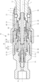
- FIG. 2 is a cross-sectional view of a female pipe coupling member according to one embodiment of the present invention.
- 2 is a cross-sectional view showing a state in which a corresponding male pipe coupling member is connected to the female pipe coupling member of FIG. 1 .
- 2 is a cross-sectional view showing a state in which a fluid pressure is applied to the female pipe coupling member of FIG. 1 when the female pipe coupling member is connected to a corresponding male pipe coupling member;
- FIG. FIG. 2 is a cross-sectional view showing a state in which a fluid pressure is applied to the female pipe coupling member of FIG. 1 before the male pipe coupling member is connected thereto;
- the female pipe fitting member (pipe fitting member) 10 is a pipe fitting member that is detachably connected to a corresponding male pipe fitting member (corresponding pipe fitting member) 1, as shown in Figures 1 to 3.
- the female pipe fitting member 10 comprises a fitting body 18 having an internal space 16 extending along a longitudinal axis L from a front end opening 12 to a rear end opening 14, and a connecting locking member 22 disposed within a locking member retaining hole 20 formed in the fitting body 18.
- the female pipe fitting member 10 further comprises a first slide member 24, a second slide member 26, and a flow path forming member 28, each of which is disposed within the internal space 16.
- the joint body 18 is composed of a front tubular member 32 and a rear tubular member 34 that are screwed together to form a tubular portion 30 that defines the internal space 16, and an intermediate member 36 that is sandwiched and held between the front tubular member 32 and the rear tubular member 34 within the internal space 16.
- the intermediate member 36 constitutes an inner extension portion 38 that extends forward from the inner peripheral surface 30a of the tubular portion 30, and a slide accommodation space 40 is defined between the inner peripheral surface 30a of the tubular portion 30 and the outer surface 38a of the inner extension portion 38.
- the front end opening 12 of the joint body 18 is adapted to receive a corresponding male pipe joint member 1.
- the rear end opening 14 is formed with a female thread portion 41 for connection to a fluid supply source (not shown).
- the first slide member 24 has a cylindrical shape, a portion of which is located within the slide accommodation space 40, and its front end 42 is arranged to be located in front of the slide accommodation space 40.
- the first slide member 24 is also displaceable back and forth in the direction of the longitudinal axis L between a forward position (FIGS. 1 and 4) and a rear position (FIGS. 2 and 3), and is biased forward by a spring 43 arranged between the first slide member 24 and the inner extension 38 of the coupling body 18.
- a spring 43 arranged between the first slide member 24 and the inner extension 38 of the coupling body 18.
- the flow path forming member 28 has a connecting portion 46 at the front end side that is connected to the corresponding male pipe coupling member 1, a valve pressing portion 48 that extends rearward in an elongated manner at the rear end side, and a first flow path portion 54 that extends rearward from a front flow path opening 50 of the connecting portion 46 to a rear flow path opening 52 generally along the longitudinal axis L.
- the flow path forming member 28 is displaceable back and forth in the direction of the longitudinal axis L between a forward position (FIGS. 1 and 4) and a rear position (FIGS. 2 and 3), and is biased forward by a spring 56 that is disposed between the flow path forming member 28 and the inner extension portion 38 of the coupling body 18.
- a stop ring 58 attached to its outer circumferential surface 28a engages with the inner extension portion 38 to prevent further forward displacement.
- the second slide member 26 has a second flow passage portion 60 that extends in the front-rear direction and communicates with the first flow passage portion 54 of the flow passage component 28.
- the second slide member 26 is displaceable in the front-rear direction in the direction of the longitudinal axis L between the rear position (FIGS. 1 and 2) and the front position (FIGS. 3 and 4), and is biased rearward by a spring 62 disposed between the second slide member 26 and the inner extension portion 38 in the joint body 18.
- the second slide member 26 is sealed between the inner peripheral surface 30a of the joint body 18 by a first seal member 64 attached to the joint body 18, and is sealed between the outer peripheral surface 28a of the flow passage component 28 by a second seal member 66 attached to the second slide member 26.
- the connecting locking member 22 is disposed within the locking member retaining hole 20 formed in the joint body 18 so as to be displaceable radially between a connecting position (FIGS. 1, 2, 3) and a disconnecting position (FIG. 4).
- the female pipe joint member 10 further includes a sleeve 68 disposed on the outer circumferential surface 18a of the joint body 18.
- the sleeve 68 is disposed so as to be displaceable back and forth in the direction of the longitudinal axis L between a locked position (FIGS. 2, 3) that holds the connecting locking member 22 in the connecting position and an unlocked position (FIGS. 1, 4) that allows the connecting locking member 22 to be displaced to the disconnecting position.
- the sleeve 68 is biased forward toward the locked position by a spring 70 disposed between the sleeve 68 and the joint body 18.
- the female pipe fitting member 10 further includes a valve member 72 disposed in the second flow path portion 60 of the second slide member 26.
- the valve member 72 is biased forward by a spring 74 disposed between the valve member 72 and the fitting body 18, and is pressed against a valve seat portion 76 formed in the second flow path portion 60.
- the second flow path portion 60 is closed by the valve member 72 being pressed against the valve seat portion 76.
- the female pipe joint member 10 further includes a first locking element 78 disposed in the inner extension portion 38 of the joint body 18, and a second locking element 80 disposed in the tubular portion 30.
- the first locking element 78 is displaceable in a first locking element retaining hole 82 formed in the inner extension portion 38 between a displacement-permitting position (FIGS. 1 and 2) protruding radially inward from the inner surface 38b of the inner extension portion 38 and a displacement-preventing position (FIGS. 3 and 4) protruding radially outward from the outer surface 38a of the inner extension portion 38.
- the second locking element 80 is displaceable in a second locking element retaining hole 84 formed in the tubular portion 30 between a retaining position (FIGS.
- the first slide member 24 In the state shown in FIG. 1, in which the male pipe coupling member 1 is not connected to the female pipe coupling member 10 and no fluid pressure is applied from the rear end opening 14, the first slide member 24 is in the forward position, whereby the second locking member 80 is held in the holding position by the first slide member 24.
- the second locking member 80 held in the holding position engages with the locking groove of the sleeve 68 to hold the sleeve 68 in the disconnected position.
- the second slide member 26 is in the rear position, whereby the first locking member 78 is freely displaceable between a radially outer displacement prevention position and a radially inner displacement allowance position.
- the front end surface 2 of the male pipe coupling member 1 first pushes the first slide member 24 backward, and then pushes the flow path component member 28 backward.
- the second locking member 80 is displaced radially inward by the sleeve 68, which is biased forward by the spring 70, to the release position.
- the sleeve 68 is displaced further forward by the spring 70, which displaces the connecting locking member 22 radially inward to the connecting position.
- the connecting locking member 22 in the connecting position engages with the locking groove 3 of the male pipe coupling member 1 to connect the male pipe coupling member 1 to the female pipe coupling member 10.
- the connecting locking member 22 is supported from the radial outside by the sleeve 68 in the locked position, and is held in the connecting position.
- the flow path component 28 has its connection portion 46 inserted into the flow path 4 of the male pipe coupling member 1 and is connected, and is pushed to a rear position by the front end surface 2 of the male pipe coupling member 1.
- the second slide member 26 when fluid is supplied from the fluid supply source connected to the rear end opening 14 and fluid pressure is applied from the rear end opening 14 side, the second slide member 26 is displaced to a forward position by the fluid pressure as shown in FIG. 3.
- the valve member 72 arranged in the second flow path section 60 of the second slide member 26 is initially displaced forward together with the second slide member 26, but is prevented from moving forward by abutting against the valve pressing portion 48 of the flow path forming member 28 along the way.
- valve member 72 is pressed against the valve seat portion 76 of the second slide member 26 until it abuts against the valve pressing portion 48, remaining in the closed position that closes the second flow path section 60, but as the second slide member 26 displaces to the forward position, it abuts against the valve pressing portion 48 and is prevented from moving forward, displacing backward relative to the second slide member 26 to the open position that opens the second flow path section 60.
- the valve member 72 is in the open position, the flow path from the rear end opening 14 to the forward flow path opening 50 of the flow path component 28 is connected, and the fluid supplied from the fluid supply source passes through the female pipe fitting member 10 and is supplied to the male pipe fitting member 1.
- the male pipe coupling member 1 cannot be inserted to the specified position because it engages with the first slide member 24 held in the forward position. Since the male pipe coupling member 1 cannot be inserted to the specified position, the operator can easily recognize that the female pipe coupling member 10 is already under fluid pressure and cannot be connected.
- the connecting locking member, the first locking element, and the second locking element are spherical members, but they can also be other shapes.
- the connecting locking member can be a chuck-shaped member that swings between a connecting position and a disconnecting position.
- the inner extension part of the joint body can extend rearward from the inner peripheral surface of the tubular part, a part of the first slide member is located radially inside the inner extension part, and a part of the second slide member is located radially outside the inner extension part.
- the first locking element can be configured to protrude radially inward from the inner extension part at the displacement prevention position and engage with the first slide member, and then displace radially outward from there to the displacement allowance position.
- terms indicating directions such as “front”, “rear”, “forward”, and “rear” in the present invention and the above embodiment are used simply to indicate the relative positional relationship in the configuration of the invention, and do not necessarily mean the direction in the actual installation state or usage state.
Landscapes
- Quick-Acting Or Multi-Walled Pipe Joints (AREA)
Abstract
[Problem] To provide a pipe joint member with which an operator can more reliably recognize that fluid pressure is being applied to the pipe joint member when an attempt was made to connect a corresponding pipe joint member while fluid pressure was applied to the pipe joint member. [Solution] A female pipe joint member 10 is removably connected to a corresponding male pipe joint member 1. When the female pipe joint member 10 receives fluid pressure from the rear-end opening 14 with the male pipe joint member 1 in a disconnected state, a second slide member 26 is displaced to the forward position, and a first lock 78 is held in a displacement-preventing position by the second slide member 26. This prevents a first slide member 24 from being displaced from a forward position to a rearward position. If an attempt is made to insert the male pipe joint member 1 into an internal space 16 of the female pipe joint member 10, a front end surface 2 of the male pipe joint member 1 engages with the first slide member 24 and the male pipe joint member 1 cannot be inserted to a predetermined position where connection will be completed.
Description
本発明は、対応管継手部材に着脱可能に連結される管継手部材に関し、特に管継手部材に流体圧力がかかっている状態での対応管継手部材の連結を防止するようにした管継手部材に関する。
The present invention relates to a pipe coupling member that is detachably connected to a corresponding pipe coupling member, and in particular to a pipe coupling member that is designed to prevent the corresponding pipe coupling member from being connected when fluid pressure is applied to the pipe coupling member.
燃料電池車に充填される水素ガスのような高圧流体を取り扱う管継手部材においては、十分な安全性を確保する必要がある。特に、流体供給源に接続された管継手部材に流体供給源からの高い流体圧力がかかっている状態で対応管継手部材を連結してしまうと、高圧流体が外部に勢いよく噴き出して危険である。また、高圧流体が吹き出すことにより対応管継手部材が吹き飛ばされる虞もある。そのため、例えば特許文献1においては、管継手部材に流体圧力がかかっている状態では対応管継手部材を管継手部材に連結できないようになっている。具体的には、連結されていない状態で流体圧力がかかったときには、管継手部材に内蔵された弁部材が開位置にまで変位することが阻止され、また対応管継手部材を連結保持するための施錠部材を施錠位置に保持するための抑え部材が動作しないようになっている。これにより、流体供給源に接続された管継手部材に対応管継手部材を挿入しても弁部材は開状態とはならないため高圧流体が噴き出すことはない。また抑え部材が動作しないことにより管継手部材に流体圧力がかかった状態であることを操作者が認識することができる。
In pipe coupling members that handle high-pressure fluids such as hydrogen gas that is filled in fuel cell vehicles, sufficient safety must be ensured. In particular, if a corresponding pipe coupling member is connected to a pipe coupling member connected to a fluid supply source while high fluid pressure from the fluid supply source is being applied, the high-pressure fluid will spurt out to the outside, which is dangerous. There is also a risk that the corresponding pipe coupling member will be blown away by the high-pressure fluid being spurted out. For this reason, for example, in Patent Document 1, the corresponding pipe coupling member cannot be connected to the pipe coupling member while fluid pressure is being applied to the pipe coupling member. Specifically, when fluid pressure is applied in a non-connected state, the valve member built into the pipe coupling member is prevented from displacing to the open position, and the holding member for holding the locking member for connecting and holding the corresponding pipe coupling member in the locked position is not operated. As a result, even if the corresponding pipe coupling member is inserted into the pipe coupling member connected to the fluid supply source, the valve member does not open, so high-pressure fluid will not spurt out. In addition, the holding member does not operate, so the operator can recognize that the pipe coupling member is under fluid pressure.
上述の従来の管継手部材によれば、管継手部材に流体圧力がかかっている状態で対応管継手部材が連結されることを防止することは可能となる。しかしながら、操作者は、対応管継手部材を所定位置にまで挿入できているにも関わらず抑え部材が動作しないため抑え部材の動きが悪くなっていると考えて抑え部材を無理に操作する可能性がある。又は、対応管継手部材の挿入がまだ足りていないと考えて対応管継手部材を無理に挿入しようとする可能性がある。このような無理な操作をすると、管継手部材が破損したり、作業者が怪我をしたりする虞がある。
The conventional pipe coupling members described above make it possible to prevent the corresponding pipe coupling member from being connected when fluid pressure is applied to the pipe coupling member. However, when the corresponding pipe coupling member has been inserted to the specified position, the operator may think that the pressing member is not moving properly because the pressing member does not operate, and may try to forcibly operate the pressing member. Or, the operator may think that the corresponding pipe coupling member has not been inserted sufficiently and may try to forcibly insert the corresponding pipe coupling member. Such forcible operation may damage the pipe coupling member or injure the operator.
そこで本発明は、管継手部材に流体圧力がかかっている状態で対応管継手部材を連結しようとしたときに、操作者が管継手部材に流体圧力がかかっていることをより確実に認識できるようにした管継手部材を提供することを目的とする。
The present invention aims to provide a pipe coupling member that allows an operator to more reliably recognize that fluid pressure is being applied to a pipe coupling member when attempting to connect a corresponding pipe coupling member while fluid pressure is being applied to the pipe coupling member.
すなわち本発明は、
対応管継手部材に着脱可能に連結される管継手部材であって、
前端開口、後端開口、及び前記前端開口と前記後端開口との間に延びる内部空間を有する管状部、並びに前記内部空間内において前記管状部の内周面から延びる内側延在部を有する継手本体と、
前記継手本体に取り付けられ、前記前端開口から前記内部空間内の所定位置にまで挿入された対応管継手部材に係合して前記対応管継手部材を当該管継手部材に連結する連結位置と、前記対応管継手部材から外れて前記対応管継手部材の当該管継手部材との連結を解除する連結解除位置との間で変位可能とされた連結施錠部材と、
前記内部空間内に配置され、前記対応管継手部材が前記所定位置にまで挿入されるときに前記対応管継手部材によって押されて前方位置から後方位置にまで変位するようにされた第1スライド部材と、
前記内部空間内に配置され、前記後端開口の側から流体圧力を受けたときに後方位置から前方位置に変位するようにされた第2スライド部材と、
前記内側延在部に配置された第1施錠子であって、前記第1スライド部材が前記前方位置から前記後方位置にまで変位することを阻止する変位阻止位置と、前記第1スライド部材が前記前方位置から前記後方位置にまで変位することを許容する変位許容位置との間で変位可能とされた第1施錠子と、
を備え、
前記第2スライド部材が前記前方位置に変位したときに、前記第1施錠子が前記第2スライド部材によって変位阻止位置に保持されるようにされた、管継手部材を提供する。 That is, the present invention provides:
A pipe coupling member that is detachably connected to a corresponding pipe coupling member,
a fitting body including a tubular portion having a front end opening, a rear end opening, and an internal space extending between the front end opening and the rear end opening, and an inner extension portion extending from an inner circumferential surface of the tubular portion within the internal space;
a coupling locking member attached to the coupling body, the coupling locking member being displaceable between a coupling position where the coupling locking member engages with a corresponding pipe coupling member inserted from the front end opening to a predetermined position within the internal space to couple the corresponding pipe coupling member to the corresponding pipe coupling member, and a coupling release position where the coupling locking member disengages from the corresponding pipe coupling member to release the connection between the corresponding pipe coupling member and the corresponding pipe coupling member;
a first slide member disposed within the internal space and configured to be pushed by the corresponding pipe coupling member and displaced from a front position to a rear position when the corresponding pipe coupling member is inserted to the predetermined position;
a second slide member disposed within the internal space and adapted to be displaced from a rear position to a front position when fluid pressure is applied from the rear end opening side;
a first locking element disposed on the inner extending portion and displaceable between a displacement preventing position that prevents the first slide member from displacing from the front position to the rear position and a displacement allowing position that allows the first slide member to displace from the front position to the rear position;
Equipped with
The pipe joint member is provided such that, when the second slide member is displaced to the forward position, the first locking element is held in a displacement prevention position by the second slide member.
当該管継手部材においては、対応管継手部材が連結されていない状態で後端開口の側から流体圧力を受けたときに第2スライド部材が前方位置に変位し、それにより第1施錠子が変位阻止位置に保持される。その結果、第1スライド部材が前方位置から後方位置に変位することが阻止される。そのため、当該管継手部材に対応管継手部材を挿入しようとしても、第1スライド部材に当たって連結が完了する所定位置にまで挿入することができない。操作者は、対応管継手部材が所定位置にまで挿入できないことにより、管継手部材に流体圧力が既にかかっていることを容易に認識することが可能となる。
When this pipe coupling member receives fluid pressure from the rear end opening while the corresponding pipe coupling member is not connected, the second slide member is displaced to a forward position, thereby holding the first locking element in a displacement prevention position. As a result, the first slide member is prevented from displacing from the forward position to the rear position. Therefore, even if an attempt is made to insert a corresponding pipe coupling member into this pipe coupling member, it will hit the first slide member and will not be able to be inserted to the specified position where connection is completed. Since the corresponding pipe coupling member cannot be inserted to the specified position, the operator can easily recognize that fluid pressure is already being applied to the pipe coupling member.
具体的には、
前記内側延在部が前記管状部の内周面から前方に延びて前記内周面との間にスライド収容空間を画定し、
前記第1スライド部材が少なくとも部分的に前記スライド収容空間内に位置し、
前記第2スライド部材が少なくとも部分的に前記内側延在部の径方向内側に位置し、
前記第1施錠子は、前記変位阻止位置において前記内側延在部から径方向外側に突出して前記第1スライド部材に係合するようにすることができる。 in particular,
The inner extension portion extends forward from an inner circumferential surface of the tubular portion to define a slide receiving space between the inner extension portion and the inner circumferential surface,
the first slide member is at least partially located within the slide receiving space;
the second slide member being at least partially located radially inward of the inner extension;
The first locking element may be configured to protrude radially outward from the inner extending portion at the displacement prevention position and engage with the first slide member.
また、
前記継手本体の外周面上に配置され、前記連結施錠部材を前記連結位置に保持する施錠位置と、前記連結施錠部材が前記連結解除位置に変位することを許容する解錠位置との間で変位可能とされたスリーブと、
前記管状部に形成された施錠子保持孔内に配置された第2施錠子であって、前記スリーブに係合して前記スリーブを前記連結解除位置に保持する保持位置と、前記スリーブが前記連結解除位置から前記施錠位置に変位することを許容する保持解除位置と、の間で変位可能とされた第2施錠子と、
を更に備え、
前記第1スライド部材が前記前方位置にあるときには、前記第2施錠子が前記第1スライド部材によって前記保持位置に保持され、
前記第1スライド部材が前記後方位置にあるときには、前記第2施錠子が前記保持解除位置に変位可能となるようにすることができる。 Also,
a sleeve disposed on an outer circumferential surface of the joint body and displaceable between a locked position that holds the connection locking member in the connection position and an unlocked position that allows the connection locking member to be displaced to the disconnected position;
a second locking element disposed in a locking element holding hole formed in the tubular portion, the second locking element being displaceable between a holding position where the second locking element engages with the sleeve to hold the sleeve in the disconnected position and a holding release position where the second locking element allows the sleeve to move from the disconnected position to the locked position;
Further comprising:
When the first slide member is in the forward position, the second locking element is held in the holding position by the first slide member,
When the first slide member is in the rear position, the second locking element can be displaced to the retention release position.
さらに、
前記内部空間内に配置され、前記内部空間内に挿入された対応管継手部材に接続される前端側の接続部、後端側の弁押圧部、及び前記接続部から後方に延びる第1流路部を有し、前記対応管継手部材が前記所定位置にまで挿入されたときに前方位置から後方位置にまで変位する流路構成部材と、
前記流路構成部材の後方に配置された弁部材と、
前記弁部材を前方側に付勢するスプリングと、
を更に備え、
前記第2スライド部材は、前後方向に延びて前記第1流路部に連通する第2流路部を有し、
前記弁部材は、前記スプリングによって前記第2スライド部材に押し付けられて前記第2流路部を閉止する閉止位置と、前記第2スライド部材に対して相対的に後方に変位して前記第2流路部を開放する開放位置との間で前記第2スライド部材に対して変位可能とされ、
前記流路構成部材が前記前方位置にあるときには、前記弁部材は、前記第2スライド部材が前記前方位置に変位するときに前記第2スライド部材とともに前方に移動して、前記閉止位置のままとなり、
前記流路構成部材が前記後方位置にあるときには、前記弁部材は、前記第2スライド部材が前記前方位置に変位する途中で前記流路構成部材の前記弁押圧部に当接して前方への移動が阻止されて、前記開放位置にとなるようにすることができる。 moreover,
a flow path forming member that is disposed within the internal space, the flow path forming member having a front end side connection portion connected to a corresponding pipe coupling member inserted into the internal space, a rear end side valve pressing portion, and a first flow path portion extending rearward from the connection portion, the flow path forming member being displaced from a front position to a rear position when the corresponding pipe coupling member is inserted to the predetermined position;
a valve member disposed behind the flow path component;
A spring that biases the valve member forward;
Further comprising:
The second slide member has a second flow path portion extending in the front-rear direction and communicating with the first flow path portion,
the valve member is displaceable with respect to the second slide member between a closing position where the valve member is pressed against the second slide member by the spring to close the second flow path portion and an opening position where the valve member is displaced rearward relative to the second slide member to open the second flow path portion,
When the flow path forming member is in the forward position, the valve member moves forward together with the second slide member when the second slide member is displaced to the forward position, and remains in the closed position,
When the flow path forming member is in the rear position, the valve member can be prevented from moving forward by abutting the valve pressing portion of the flow path forming member as the second slide member is displaced to the forward position, thereby being brought into the open position.
以下、本発明に係る管継手部材の実施形態を添付図面に基づき説明する。
Below, an embodiment of a pipe joint member according to the present invention will be described with reference to the attached drawings.
本発明の一実施形態に係る雌型管継手部材(管継手部材)10は、図1乃至図3に示すように、対応する雄型管継手部材(対応管継手部材)1に着脱可能に連結される管継手部材である。
The female pipe fitting member (pipe fitting member) 10 according to one embodiment of the present invention is a pipe fitting member that is detachably connected to a corresponding male pipe fitting member (corresponding pipe fitting member) 1, as shown in Figures 1 to 3.
当該雌型管継手部材10は、図1に示すように、前端開口12から後端開口14にまで長手軸線Lに沿って延びる内部空間16を有する継手本体18と、継手本体18に形成された施錠部材保持孔20内に配置された連結施錠部材22とを備える。雌型管継手部材10はさらに、内部空間16内にそれぞれ配置された、第1スライド部材24、第2スライド部材26、及び流路構成部材28を備える。
As shown in FIG. 1, the female pipe fitting member 10 comprises a fitting body 18 having an internal space 16 extending along a longitudinal axis L from a front end opening 12 to a rear end opening 14, and a connecting locking member 22 disposed within a locking member retaining hole 20 formed in the fitting body 18. The female pipe fitting member 10 further comprises a first slide member 24, a second slide member 26, and a flow path forming member 28, each of which is disposed within the internal space 16.
当該実施形態においては、継手本体18は、内部空間16を画定する管状部30を形成するように相互に螺合された前方管状部材32及び後方管状部材34と、内部空間16内において前方管状部材32と後方管状部材34との間に挟まれて保持された中間部材36と、により構成されている。中間部材36は、管状部30の内周面30aから前方に延びる内側延在部38を構成しており、管状部30の内周面30aと内側延在部38の外側面38aとの間にはスライド収容空間40が画定されている。後述するように、継手本体18の前端開口12は対応する雄型管継手部材1を受け入れるようにされている。また、後端開口14には、流体供給源(図示しない)に接続するための雌ねじ部41が形成されている。
In this embodiment, the joint body 18 is composed of a front tubular member 32 and a rear tubular member 34 that are screwed together to form a tubular portion 30 that defines the internal space 16, and an intermediate member 36 that is sandwiched and held between the front tubular member 32 and the rear tubular member 34 within the internal space 16. The intermediate member 36 constitutes an inner extension portion 38 that extends forward from the inner peripheral surface 30a of the tubular portion 30, and a slide accommodation space 40 is defined between the inner peripheral surface 30a of the tubular portion 30 and the outer surface 38a of the inner extension portion 38. As described below, the front end opening 12 of the joint body 18 is adapted to receive a corresponding male pipe joint member 1. In addition, the rear end opening 14 is formed with a female thread portion 41 for connection to a fluid supply source (not shown).
第1スライド部材24は、筒状の形状を有し、その一部がスライド収容空間40内に位置し、その前端部42はスライド収容空間40の前方に位置するように配置されている。また、第1スライド部材24は、前方位置(図1、図4)と後方位置(図2、図3)との間で長手軸線Lの方向で前後に変位可能とされ、継手本体18の内側延在部38との間に配置されたスプリング43によって前方に付勢されている。第1スライド部材24は、前方位置にあるときにはその係止段部44が流路構成部材28に係合しており、それ以上前方に変位しないようになっている。
The first slide member 24 has a cylindrical shape, a portion of which is located within the slide accommodation space 40, and its front end 42 is arranged to be located in front of the slide accommodation space 40. The first slide member 24 is also displaceable back and forth in the direction of the longitudinal axis L between a forward position (FIGS. 1 and 4) and a rear position (FIGS. 2 and 3), and is biased forward by a spring 43 arranged between the first slide member 24 and the inner extension 38 of the coupling body 18. When the first slide member 24 is in the forward position, its locking step 44 engages with the flow path forming member 28, preventing it from being displaced further forward.
流路構成部材28は、対応する雄型管継手部材1に接続される前端側の接続部46と、後端側において後方に細長く延びる弁押圧部48と、接続部46の前方流路開口50から後方に後方流路開口52にまで概して長手軸線Lに沿って延びる第1流路部54とを有する。また、流路構成部材28は、前方位置(図1、図4)と後方位置(図2、図3)との間で長手軸線Lの方向で前後に変位可能とされ、継手本体18の内側延在部38との間に配置されたスプリング56によって前方に付勢されている。流路構成部材28は、前方位置にあるときには、その外周面28aに取り付けられたストップリング58が内側延在部38に係合して、それ以上前方に変位しないようになっている。
The flow path forming member 28 has a connecting portion 46 at the front end side that is connected to the corresponding male pipe coupling member 1, a valve pressing portion 48 that extends rearward in an elongated manner at the rear end side, and a first flow path portion 54 that extends rearward from a front flow path opening 50 of the connecting portion 46 to a rear flow path opening 52 generally along the longitudinal axis L. The flow path forming member 28 is displaceable back and forth in the direction of the longitudinal axis L between a forward position (FIGS. 1 and 4) and a rear position (FIGS. 2 and 3), and is biased forward by a spring 56 that is disposed between the flow path forming member 28 and the inner extension portion 38 of the coupling body 18. When the flow path forming member 28 is in the forward position, a stop ring 58 attached to its outer circumferential surface 28a engages with the inner extension portion 38 to prevent further forward displacement.
第2スライド部材26は、前後方向に延びて流路構成部材28の第1流路部54に連通した第2流路部60を有する。また第2スライド部材26は、後方位置(図1、図2)と前方位置(図3、図4)との間で長手軸線Lの方向で前後に変位可能とされ、継手本体18内の内側延在部38との間に配置されたスプリング62によって後方に付勢されている。この第2スライド部材26は、継手本体18に取り付けられた第1シール部材64により継手本体18の内周面30aとの間が密封され、第2スライド部材26に取り付けられた第2シール部材66により流路構成部材28の外周面28aとの間が密封されている。第2スライド部材26及び流路構成部材28がそれぞれの前方位置と後方位置との間で変位する際に、これら第1シール部材64及び第2シール部材66による密封は維持される。
The second slide member 26 has a second flow passage portion 60 that extends in the front-rear direction and communicates with the first flow passage portion 54 of the flow passage component 28. The second slide member 26 is displaceable in the front-rear direction in the direction of the longitudinal axis L between the rear position (FIGS. 1 and 2) and the front position (FIGS. 3 and 4), and is biased rearward by a spring 62 disposed between the second slide member 26 and the inner extension portion 38 in the joint body 18. The second slide member 26 is sealed between the inner peripheral surface 30a of the joint body 18 by a first seal member 64 attached to the joint body 18, and is sealed between the outer peripheral surface 28a of the flow passage component 28 by a second seal member 66 attached to the second slide member 26. When the second slide member 26 and the flow passage component 28 are displaced between their respective front and rear positions, the seal provided by the first seal member 64 and the second seal member 66 is maintained.
連結施錠部材22は、継手本体18に形成された施錠部材保持孔20内において、連結位置(図1、図2、図3)と連結解除位置(図4)との間で径方向に変位可能に配置されている。当該雌型管継手部材10はさらに、継手本体18の外周面18a上に配置されたスリーブ68を備える。このスリーブ68は、連結施錠部材22を連結位置に保持する施錠位置(図2、図3)と連結施錠部材22が連結解除位置に変位することを許容する解錠位置(図1、図4)との間で長手軸線Lの方向で前後に変位可能に配置されている。スリーブ68は、継手本体18との間に配置されたスプリング70によって施錠位置に向かって前方に付勢されている。
The connecting locking member 22 is disposed within the locking member retaining hole 20 formed in the joint body 18 so as to be displaceable radially between a connecting position (FIGS. 1, 2, 3) and a disconnecting position (FIG. 4). The female pipe joint member 10 further includes a sleeve 68 disposed on the outer circumferential surface 18a of the joint body 18. The sleeve 68 is disposed so as to be displaceable back and forth in the direction of the longitudinal axis L between a locked position (FIGS. 2, 3) that holds the connecting locking member 22 in the connecting position and an unlocked position (FIGS. 1, 4) that allows the connecting locking member 22 to be displaced to the disconnecting position. The sleeve 68 is biased forward toward the locked position by a spring 70 disposed between the sleeve 68 and the joint body 18.
当該雌型管継手部材10はさらに、第2スライド部材26の第2流路部60に配置された弁部材72を備える。この弁部材72は、継手本体18との間に配置されたスプリング74によって前方に付勢されて、第2流路部60に形成された弁座部76に押圧されている。弁部材72が弁座部76に押圧されることにより第2流路部60は閉止されている。
The female pipe fitting member 10 further includes a valve member 72 disposed in the second flow path portion 60 of the second slide member 26. The valve member 72 is biased forward by a spring 74 disposed between the valve member 72 and the fitting body 18, and is pressed against a valve seat portion 76 formed in the second flow path portion 60. The second flow path portion 60 is closed by the valve member 72 being pressed against the valve seat portion 76.
当該雌型管継手部材10はさらに、継手本体18の内側延在部38に配置された第1施錠子78と、管状部30に配置された第2施錠子80とを備える。第1施錠子78は、内側延在部38に形成された第1施錠子保持孔82内において、内側延在部38の内側面38bから径方向内側に突出した変位許容位置(図1、図2)と内側延在部38の外側面38aから径方向外側に突出した変位阻止位置(図3、図4)との間で変位可能とされている。また、第2施錠子80は、管状部30に形成された第2施錠子保持孔84内において、管状部30の外周面30bから径方向外側に突出した保持位置(図1、図4)と管状部30の内周面30aから径方向内側に突出した保持解除位置(図2、図3)との間で変位可能とされている。
The female pipe joint member 10 further includes a first locking element 78 disposed in the inner extension portion 38 of the joint body 18, and a second locking element 80 disposed in the tubular portion 30. The first locking element 78 is displaceable in a first locking element retaining hole 82 formed in the inner extension portion 38 between a displacement-permitting position (FIGS. 1 and 2) protruding radially inward from the inner surface 38b of the inner extension portion 38 and a displacement-preventing position (FIGS. 3 and 4) protruding radially outward from the outer surface 38a of the inner extension portion 38. The second locking element 80 is displaceable in a second locking element retaining hole 84 formed in the tubular portion 30 between a retaining position (FIGS. 1 and 4) protruding radially outward from the outer circumferential surface 30b of the tubular portion 30 and a retaining release position (FIGS. 2 and 3) protruding radially inward from the inner circumferential surface 30a of the tubular portion 30.
当該雌型管継手部材10に雄型管継手部材1が連結されておらず且つ後端開口14から流体圧力を受けていない図1の状態においては、第1スライド部材24は前方位置にあり、それにより第2施錠子80が第1スライド部材24によって保持位置に保持される。保持位置に保持された第2施錠子80は、スリーブ68の係止溝に係合してスリーブ68を連結解除位置に保持する。また、第2スライド部材26は、後方位置にあり、それにより第1施錠子78は径方向外側の変位阻止位置と径方向内側の変位許容位置との間で自在に変位可能な状態となっている。
In the state shown in FIG. 1, in which the male pipe coupling member 1 is not connected to the female pipe coupling member 10 and no fluid pressure is applied from the rear end opening 14, the first slide member 24 is in the forward position, whereby the second locking member 80 is held in the holding position by the first slide member 24. The second locking member 80 held in the holding position engages with the locking groove of the sleeve 68 to hold the sleeve 68 in the disconnected position. The second slide member 26 is in the rear position, whereby the first locking member 78 is freely displaceable between a radially outer displacement prevention position and a radially inner displacement allowance position.
図1の状態で対応する雄型管継手部材1を前端開口12から内部空間16に挿入していくと、雄型管継手部材1の前端面2がまず第1スライド部材24を後方に押し、次いで流路構成部材28を後方に押す。図2に示すように、雄型管継手部材1を所定位置にまで挿入すると、スプリング70によって前方に付勢されているスリーブ68によって第2施錠子80が径方向内側に変位して保持解除位置となる。スリーブ68はスプリング70によってさらに前方に変位し、それにより連結施錠部材22が径方向内側に変位して連結位置となる。連結位置となった連結施錠部材22は、雄型管継手部材1の係止溝3に係合して雄型管継手部材1を当該雌型管継手部材10に連結する。また連結施錠部材22は、施錠位置となったスリーブ68によって径方向外側から支持されて、連結位置に保持される。流路構成部材28は、その接続部46が雄型管継手部材1の流路4内に挿入されて接続されるとともに、雄型管継手部材1の前端面2によって後方位置にまで押される。
1, when the corresponding male pipe coupling member 1 is inserted into the internal space 16 from the front end opening 12, the front end surface 2 of the male pipe coupling member 1 first pushes the first slide member 24 backward, and then pushes the flow path component member 28 backward. As shown in FIG. 2, when the male pipe coupling member 1 is inserted to a predetermined position, the second locking member 80 is displaced radially inward by the sleeve 68, which is biased forward by the spring 70, to the release position. The sleeve 68 is displaced further forward by the spring 70, which displaces the connecting locking member 22 radially inward to the connecting position. The connecting locking member 22 in the connecting position engages with the locking groove 3 of the male pipe coupling member 1 to connect the male pipe coupling member 1 to the female pipe coupling member 10. The connecting locking member 22 is supported from the radial outside by the sleeve 68 in the locked position, and is held in the connecting position. The flow path component 28 has its connection portion 46 inserted into the flow path 4 of the male pipe coupling member 1 and is connected, and is pushed to a rear position by the front end surface 2 of the male pipe coupling member 1.
図2の連結状態で後端開口14に接続された流体供給源から流体が供給されて後端開口14の側から流体圧力がかかると、図3に示すように第2スライド部材26が流体圧力によって前方位置にまで変位する。第2スライド部材26の第2流路部60内に配置されている弁部材72は、初めは第2スライド部材26とともに前方に変位するが、途中で流路構成部材28の弁押圧部48に当接して前方への移動が阻止される。よって、弁部材72は、弁押圧部48に当接するまでは第2スライド部材26の弁座部76に押し付けられて第2流路部60を閉止する閉止位置のままであるが、第2スライド部材26が前方位置にまで変位する途中で弁押圧部48に当接して前方への移動が阻止されることにより第2スライド部材26に対して相対的に後方に変位して第2流路部60を開放する開放位置となる。弁部材72が開放位置となることにより、後端開口14から流路構成部材28の前方流路開口50までの流路が連通し、流体供給源から供給される流体が当該雌型管継手部材10を通って雄型管継手部材1に供給されるようになる。
2, when fluid is supplied from the fluid supply source connected to the rear end opening 14 and fluid pressure is applied from the rear end opening 14 side, the second slide member 26 is displaced to a forward position by the fluid pressure as shown in FIG. 3. The valve member 72 arranged in the second flow path section 60 of the second slide member 26 is initially displaced forward together with the second slide member 26, but is prevented from moving forward by abutting against the valve pressing portion 48 of the flow path forming member 28 along the way. Thus, the valve member 72 is pressed against the valve seat portion 76 of the second slide member 26 until it abuts against the valve pressing portion 48, remaining in the closed position that closes the second flow path section 60, but as the second slide member 26 displaces to the forward position, it abuts against the valve pressing portion 48 and is prevented from moving forward, displacing backward relative to the second slide member 26 to the open position that opens the second flow path section 60. When the valve member 72 is in the open position, the flow path from the rear end opening 14 to the forward flow path opening 50 of the flow path component 28 is connected, and the fluid supplied from the fluid supply source passes through the female pipe fitting member 10 and is supplied to the male pipe fitting member 1.
連結を解除するときには、流体供給源からの流体の供給を停止して後端開口14の側からの流体圧力がかからない状態(図2)とし、スリーブ68を保持解除位置に変位させる。そうすると連結施錠部材22は、雄型管継手部材1の係止溝3から外れて雌型管継手部材10との連結を解除する連結解除位置に変位可能となる。この状態で雄型管継手部材1を雌型管継手部材10から引き抜くことにより連結は解除される。
When disconnecting, the supply of fluid from the fluid supply source is stopped so that no fluid pressure is applied from the rear end opening 14 side (Figure 2), and the sleeve 68 is displaced to the release position. This causes the connection locking member 22 to disengage from the locking groove 3 of the male pipe coupling member 1 and displace to the disconnection position where the connection with the female pipe coupling member 10 is released. In this state, the male pipe coupling member 1 is pulled out of the female pipe coupling member 10 to disconnect the connection.
一方で、雄型管継手部材1が接続されていない図1の状態で後端開口14の側から流体圧力かかると、図4に示すように、第2スライド部材26が弁部材72とともに前方位置にまで変位する。そうすると、第2スライド部材26によって第1施錠子78が径方向外側に変位されて変位阻止位置に保持される。これにより、第1スライド部材24の後端部86が第1施錠子78と係合する状態となり、第1スライド部材24は前方位置から後方位置に向かって変位することが阻止される。弁部材72は、第2スライド部材26とともに前方に変位するため、第2スライド部材26に対して相対的には変位しない。よって、弁部材72は、第2流路部60を閉止する閉止位置を維持している。この状態で雄型管継手部材1を前端開口12から挿入しようとしても、雄型管継手部材1の前端面2が前方位置に保持された第1スライド部材24に当接するため、雄型管継手部材1をそれ以上挿入することができない。また、雄型管継手部材1は流路構成部材28に当接しないので、流路構成部材28は後方位置に向かって変位しない。よって、第2スライド部材26が前方位置にまで変位しているが、弁部材72は流路構成部材28の弁押圧部48に当接しないので開放位置にはならず閉止位置のままとなる。
On the other hand, when fluid pressure is applied from the rear end opening 14 side in the state shown in FIG. 1 with the male pipe coupling member 1 not connected, the second slide member 26 is displaced to the forward position together with the valve member 72 as shown in FIG. 4. Then, the first locking element 78 is displaced radially outward by the second slide member 26 and held in the displacement prevention position. As a result, the rear end portion 86 of the first slide member 24 is engaged with the first locking element 78, and the first slide member 24 is prevented from displacing from the forward position to the rear position. The valve member 72 is displaced forward together with the second slide member 26, so it is not displaced relative to the second slide member 26. Therefore, the valve member 72 maintains the closed position that closes the second flow path portion 60. Even if an attempt is made to insert the male pipe coupling member 1 from the front end opening 12 in this state, the front end surface 2 of the male pipe coupling member 1 abuts against the first slide member 24 held in the forward position, so the male pipe coupling member 1 cannot be inserted any further. In addition, since the male pipe fitting member 1 does not abut against the flow path component 28, the flow path component 28 does not displace toward the rear position. Therefore, although the second slide member 26 is displaced to the forward position, the valve member 72 does not abut against the valve pressing portion 48 of the flow path component 28, so it does not move to the open position and remains in the closed position.
当該雌型管継手部材10においては、上述のとおり、流体圧力がかかっている状態で対応する雄型管継手部材1を連結しようとしても、雄型管継手部材1が前方位置に保持された第1スライド部材24に係合するため、所定位置にまで挿入することができない。操作者は、雄型管継手部材1が所定位置にまで挿入できないことにより、当該雌型管継手部材10に既に流体圧力がかかっていて連結できない状態であることを容易に認識することが可能となる。
As described above, even if an attempt is made to connect the corresponding male pipe coupling member 1 to the female pipe coupling member 10 while fluid pressure is being applied, the male pipe coupling member 1 cannot be inserted to the specified position because it engages with the first slide member 24 held in the forward position. Since the male pipe coupling member 1 cannot be inserted to the specified position, the operator can easily recognize that the female pipe coupling member 10 is already under fluid pressure and cannot be connected.
以上に本発明の実施形態について説明をしたが、本発明はこれら実施形態に限定されるものではない。例えば、上記実施形態においては、連結施錠部材、第1施錠子、及び第2施錠子は球状部材となっているが、他の形状とすることもできる。特に連結施錠部材は、連結位置と連結解除位置との間で揺動するチャック状部材とすることもできる。また、継手本体の内側延在部が管状部の内周面から後方に延び、第1スライド部材の一部が内側延在部の径方向内側に位置し、第2スライド部材の一部が内側延在部の径方向外側に位置するようにすることもできる。その場合には、第1施錠子は変位阻止位置において内側延在部から径方向内側に突出して第1スライド部材に係合し、そこから径方向外側に変位して変位許容位置となるように構成することができる。なお、本願発明及び上記実施形態における「前」、「後」、「前方」、「後方」などの方向を示す用語は、単に発明の構成における相対的な位置関係を示すために用いているのであり、実際の設置状態や使用状態における方向を必ずしも意味するものではない。
Although the embodiments of the present invention have been described above, the present invention is not limited to these embodiments. For example, in the above embodiment, the connecting locking member, the first locking element, and the second locking element are spherical members, but they can also be other shapes. In particular, the connecting locking member can be a chuck-shaped member that swings between a connecting position and a disconnecting position. In addition, the inner extension part of the joint body can extend rearward from the inner peripheral surface of the tubular part, a part of the first slide member is located radially inside the inner extension part, and a part of the second slide member is located radially outside the inner extension part. In that case, the first locking element can be configured to protrude radially inward from the inner extension part at the displacement prevention position and engage with the first slide member, and then displace radially outward from there to the displacement allowance position. In addition, terms indicating directions such as "front", "rear", "forward", and "rear" in the present invention and the above embodiment are used simply to indicate the relative positional relationship in the configuration of the invention, and do not necessarily mean the direction in the actual installation state or usage state.
1 雄型管継手部材(対応管継手部材)
2 前端面
3 係止溝
4 流路
10 雌型管継手部材(管継手部材)
12 前端開口
14 後端開口
16 内部空間
18 継手本体
18a 外周面
20 施錠部材保持孔
22 連結施錠部材
24 第1スライド部材
26 第2スライド部材
28 流路構成部材
28a 外周面
30 管状部
30a 内周面
30b 外周面
32 前方管状部材
34 後方管状部材
36 中間部材
38 内側延在部
38a 外側面
38b 内側面
40 スライド収容空間
41 雌ねじ部
42 前端部
43 スプリング
44 係止段部
46 接続部
48 弁押圧部
50 前方流路開口
52 後方流路開口
54 第1流路部
56 スプリング
58 ストップリング
60 第2流路部
62 スプリング
64 第1シール部材
66 第2シール部材
68 スリーブ
70 スプリング
72 弁部材
74 スプリング
76 弁座部
78 第1施錠子
80 第2施錠子
82 第1施錠子保持孔
84 第2施錠子保持孔
86 後端部
L 長手軸線 1 Male pipe joint member (corresponding pipe joint member)
2 Front end surface 3Locking groove 4 Flow path 10 Female pipe joint member (pipe joint member)
12 Front end opening 14 Rear end opening 16Internal space 18 Joint body 18a Outer peripheral surface 20 Locking member retaining hole 22 Connecting locking member 24 First slide member 26 Second slide member 28 Flow path forming member 28a Outer peripheral surface 30 Tubular portion 30a Inner peripheral surface 30b Outer peripheral surface 32 Front tubular member 34 Rear tubular member 36 Intermediate member 38 Inner extension portion 38a Outer surface 38b Inner surface 40 Slide accommodation space 41 Female thread portion 42 Front end portion 43 Spring 44 Locking step portion 46 Connection portion 48 Valve pressing portion 50 Front flow path opening 52 Rear flow path opening 54 First flow path portion 56 Spring 58 Stop ring 60 Second flow path portion 62 Spring 64 First seal member 66 Second seal member 68 Sleeve 70 Spring 72 Valve member 74 Spring 76 Valve seat portion 78 First locking element 80 Second locking element 82 First locking element holding hole 84 Second locking element holding hole 86 Rear end portion L Longitudinal axis
2 前端面
3 係止溝
4 流路
10 雌型管継手部材(管継手部材)
12 前端開口
14 後端開口
16 内部空間
18 継手本体
18a 外周面
20 施錠部材保持孔
22 連結施錠部材
24 第1スライド部材
26 第2スライド部材
28 流路構成部材
28a 外周面
30 管状部
30a 内周面
30b 外周面
32 前方管状部材
34 後方管状部材
36 中間部材
38 内側延在部
38a 外側面
38b 内側面
40 スライド収容空間
41 雌ねじ部
42 前端部
43 スプリング
44 係止段部
46 接続部
48 弁押圧部
50 前方流路開口
52 後方流路開口
54 第1流路部
56 スプリング
58 ストップリング
60 第2流路部
62 スプリング
64 第1シール部材
66 第2シール部材
68 スリーブ
70 スプリング
72 弁部材
74 スプリング
76 弁座部
78 第1施錠子
80 第2施錠子
82 第1施錠子保持孔
84 第2施錠子保持孔
86 後端部
L 長手軸線 1 Male pipe joint member (corresponding pipe joint member)
2 Front end surface 3
12 Front end opening 14 Rear end opening 16
Claims (4)
- 対応管継手部材に着脱可能に連結される管継手部材であって、
前端開口、後端開口、及び前記前端開口と前記後端開口との間に延びる内部空間を有する管状部、並びに前記内部空間内において前記管状部の内周面から延びる内側延在部を有する継手本体と、
前記継手本体に取り付けられ、前記前端開口から前記内部空間内の所定位置にまで挿入された対応管継手部材に係合して前記対応管継手部材を当該管継手部材に連結する連結位置と、前記対応管継手部材から外れて前記対応管継手部材の当該管継手部材との連結を解除する連結解除位置との間で変位可能とされた連結施錠部材と、
前記内部空間内に配置され、前記対応管継手部材が前記所定位置にまで挿入されるときに前記対応管継手部材によって押されて前方位置から後方位置にまで変位するようにされた第1スライド部材と、
前記内部空間内に配置され、前記後端開口の側から流体圧力を受けたときに後方位置から前方位置に変位するようにされた第2スライド部材と、
前記内側延在部に配置された第1施錠子であって、前記第1スライド部材が前記前方位置から前記後方位置にまで変位することを阻止する変位阻止位置と、前記第1スライド部材が前記前方位置から前記後方位置にまで変位することを許容する変位許容位置との間で変位可能とされた第1施錠子と、
を備え、
前記第2スライド部材が前記前方位置に変位したときに、前記第1施錠子が前記第2スライド部材によって変位阻止位置に保持されるようにされた、管継手部材。 A pipe coupling member that is detachably connected to a corresponding pipe coupling member,
a fitting body including a tubular portion having a front end opening, a rear end opening, and an internal space extending between the front end opening and the rear end opening, and an inner extension portion extending from an inner circumferential surface of the tubular portion within the internal space;
a coupling locking member attached to the coupling body, the coupling locking member being displaceable between a coupling position where the coupling locking member engages with a corresponding pipe coupling member inserted from the front end opening to a predetermined position within the internal space to couple the corresponding pipe coupling member to the corresponding pipe coupling member, and a coupling release position where the coupling locking member disengages from the corresponding pipe coupling member to release the connection between the corresponding pipe coupling member and the corresponding pipe coupling member;
a first slide member disposed within the internal space and configured to be pushed by the corresponding pipe coupling member and displaced from a front position to a rear position when the corresponding pipe coupling member is inserted to the predetermined position;
a second slide member disposed within the internal space and adapted to be displaced from a rear position to a front position when fluid pressure is applied from the rear end opening side;
a first locking element disposed on the inner extending portion and displaceable between a displacement preventing position that prevents the first slide member from displacing from the front position to the rear position and a displacement allowing position that allows the first slide member to displace from the front position to the rear position;
Equipped with
The pipe joint member is configured such that, when the second slide member is displaced to the forward position, the first locking element is held in a displacement prevention position by the second slide member. - 前記内側延在部が前記管状部の内周面から前方に延びて前記内周面との間にスライド収容空間を画定し、
前記第1スライド部材が少なくとも部分的に前記スライド収容空間内に位置し、
前記第2スライド部材が少なくとも部分的に前記内側延在部の径方向内側に位置し、
前記第1施錠子は、前記変位阻止位置において前記内側延在部から径方向外側に突出して前記第1スライド部材に係合するようにされた、請求項1に記載の管継手部材。 The inner extension portion extends forward from an inner circumferential surface of the tubular portion to define a slide receiving space between the inner extension portion and the inner circumferential surface,
the first slide member is at least partially located within the slide receiving space;
the second slide member is at least partially located radially inward of the inner extension;
The pipe joint member according to claim 1 , wherein the first locking element protrudes radially outward from the inner extending portion at the displacement prevention position to engage with the first slide member. - 前記継手本体の外周面上に配置され、前記連結施錠部材を前記連結位置に保持する施錠位置と、前記連結施錠部材が前記連結解除位置に変位することを許容する解錠位置との間で変位可能とされたスリーブと、
前記管状部に形成された施錠子保持孔内に配置された第2施錠子であって、前記スリーブに係合して前記スリーブを前記連結解除位置に保持する保持位置と、前記スリーブが前記連結解除位置から前記施錠位置に変位することを許容する保持解除位置と、の間で変位可能とされた第2施錠子と、
を更に備え、
前記第1スライド部材が前記前方位置にあるときには、前記第2施錠子が前記第1スライド部材によって前記保持位置に保持され、
前記第1スライド部材が前記後方位置にあるときには、前記第2施錠子が前記保持解除位置に変位可能となるようにされた、請求項1又は2に記載の管継手部材。 a sleeve disposed on an outer circumferential surface of the joint body and displaceable between a locked position that holds the connection locking member in the connection position and an unlocked position that allows the connection locking member to be displaced to the disconnected position;
a second locking element disposed in a locking element holding hole formed in the tubular portion, the second locking element being displaceable between a holding position where the second locking element engages with the sleeve to hold the sleeve in the disconnected position and a holding release position where the sleeve is permitted to move from the disconnected position to the locked position;
Further comprising:
When the first slide member is in the forward position, the second locking element is held in the holding position by the first slide member,
3. The pipe joint member according to claim 1, wherein the second locking element is adapted to be displaceable to the retention release position when the first slide member is in the rear position. - 前記内部空間内に配置され、前記内部空間内に挿入された対応管継手部材に接続される前端側の接続部、後端側の弁押圧部、及び前記接続部から後方に延びる第1流路部を有し、前記対応管継手部材が前記所定位置にまで挿入されたときに前方位置から後方位置にまで変位する流路構成部材と、
前記流路構成部材の後方に配置された弁部材と、
前記弁部材を前方側に付勢するスプリングと、
を更に備え、
前記第2スライド部材は、前後方向に延びて前記第1流路部に連通する第2流路部を有し、
前記弁部材は、前記スプリングによって前記第2スライド部材に押し付けられて前記第2流路部を閉止する閉止位置と、前記第2スライド部材に対して相対的に後方に変位して前記第2流路部を開放する開放位置との間で前記第2スライド部材に対して変位可能とされ、
前記流路構成部材が前記前方位置にあるときには、前記弁部材は、前記第2スライド部材が前記前方位置に変位するときに前記第2スライド部材とともに前方に移動して、前記閉止位置のままとなり、
前記流路構成部材が前記後方位置にあるときには、前記弁部材は、前記第2スライド部材が前記前方位置に変位する途中で前記流路構成部材の前記弁押圧部に当接して前方への移動が阻止されて、前記開放位置にとなるようにされた、請求項1又は2に記載の管継手部材。 a flow path forming member that is disposed within the internal space, the flow path forming member having a front end side connection portion connected to a corresponding pipe coupling member inserted into the internal space, a rear end side valve pressing portion, and a first flow path portion extending rearward from the connection portion, the flow path forming member being displaced from a front position to a rear position when the corresponding pipe coupling member is inserted to the predetermined position;
a valve member disposed behind the flow path component;
A spring that biases the valve member forward;
Further comprising:
The second slide member has a second flow path portion extending in the front-rear direction and communicating with the first flow path portion,
the valve member is displaceable with respect to the second slide member between a closing position where the valve member is pressed against the second slide member by the spring to close the second flow path portion and an opening position where the valve member is displaced rearward relative to the second slide member to open the second flow path portion,
When the flow path forming member is in the forward position, the valve member moves forward together with the second slide member when the second slide member is displaced to the forward position, and remains in the closed position,
3. The pipe coupling member according to claim 1, wherein when the flow path component member is in the rear position, the valve member abuts against the valve pressing portion of the flow path component member during the displacement of the second slide member to the forward position, thereby preventing the valve member from moving forward and setting the valve member to the open position.
Applications Claiming Priority (2)
| Application Number | Priority Date | Filing Date | Title |
|---|---|---|---|
| JP2022-178835 | 2022-11-08 | ||
| JP2022178835 | 2022-11-08 |
Publications (1)
| Publication Number | Publication Date |
|---|---|
| WO2024101142A1 true WO2024101142A1 (en) | 2024-05-16 |
Family
ID=91032647
Family Applications (1)
| Application Number | Title | Priority Date | Filing Date |
|---|---|---|---|
| PCT/JP2023/038295 WO2024101142A1 (en) | 2022-11-08 | 2023-10-24 | Pipe joint member |
Country Status (1)
| Country | Link |
|---|---|
| WO (1) | WO2024101142A1 (en) |
Citations (4)
| Publication number | Priority date | Publication date | Assignee | Title |
|---|---|---|---|---|
| JPS4934020A (en) * | 1972-08-02 | 1974-03-29 | ||
| JPH06109188A (en) * | 1991-12-29 | 1994-04-19 | Toyota Motor Corp | Quick coupling |
| JPH07233891A (en) * | 1994-02-21 | 1995-09-05 | Betsuseru Kogyo:Kk | Fluid conveying coupling |
| US20180100613A1 (en) * | 2016-10-06 | 2018-04-12 | Staubli Faverges | Quick coupling |
-
2023
- 2023-10-24 WO PCT/JP2023/038295 patent/WO2024101142A1/en unknown
Patent Citations (4)
| Publication number | Priority date | Publication date | Assignee | Title |
|---|---|---|---|---|
| JPS4934020A (en) * | 1972-08-02 | 1974-03-29 | ||
| JPH06109188A (en) * | 1991-12-29 | 1994-04-19 | Toyota Motor Corp | Quick coupling |
| JPH07233891A (en) * | 1994-02-21 | 1995-09-05 | Betsuseru Kogyo:Kk | Fluid conveying coupling |
| US20180100613A1 (en) * | 2016-10-06 | 2018-04-12 | Staubli Faverges | Quick coupling |
Similar Documents
| Publication | Publication Date | Title |
|---|---|---|
| WO2009107788A1 (en) | Socket for pipe coupling and pipe coupling | |
| US6237631B1 (en) | Low spill quick disconnect coupling | |
| US4007909A (en) | Full flow valved fitting | |
| US10663099B2 (en) | Pipe coupling comprising female coupling member and male coupling member | |
| US7731243B2 (en) | Coupling element for removably joining pipes | |
| US8256803B2 (en) | Socket for pipe joint and pipe joint | |
| US8186649B2 (en) | Female coupling member and male coupling member | |
| EP3171067B1 (en) | Non-spill connect under pressure coupler | |
| US9939096B2 (en) | Female element and coupling intended to form the disconnectable connection of two fluid pipe lines | |
| CN107401676A (en) | LNG nozzle safe locking mechanisms | |
| CN101978205A (en) | Fluid filling and/or extracting connector and assembly comprising a connector and a tap | |
| JP2018054124A (en) | Joint and hydraulic brake circuit for stroke vehicle combined with joint | |
| JPH0830550B2 (en) | Quick disconnect female fitting | |
| US5255699A (en) | Nipple with integral crossbar actuator and check valve | |
| US20050212289A1 (en) | Connecting coupling with a sliding sleeve and collet chucks | |
| US6050298A (en) | Safety circuit breaker for pressurized-fluid handling installation | |
| TWI753420B (en) | Valve structure, joint member and pipe joint | |
| WO2024101142A1 (en) | Pipe joint member | |
| US7537246B2 (en) | Pipe coupler | |
| JP4348589B2 (en) | Connector with safety release device | |
| US20040016464A1 (en) | Fluid coupler automatically uncouplable in an emergency | |
| WO2012066588A1 (en) | Coupler | |
| JPH11280975A (en) | Pipe coupling | |
| US5310161A (en) | High pressure gas line breakaway connector | |
| CN217519446U (en) | Fluid coupling |