WO2024100765A1 - 射出成形機の制御装置 - Google Patents
射出成形機の制御装置 Download PDFInfo
- Publication number
- WO2024100765A1 WO2024100765A1 PCT/JP2022/041552 JP2022041552W WO2024100765A1 WO 2024100765 A1 WO2024100765 A1 WO 2024100765A1 JP 2022041552 W JP2022041552 W JP 2022041552W WO 2024100765 A1 WO2024100765 A1 WO 2024100765A1
- Authority
- WO
- WIPO (PCT)
- Prior art keywords
- amount
- heat
- heater
- calculation unit
- heat generation
- Prior art date
- Legal status (The legal status is an assumption and is not a legal conclusion. Google has not performed a legal analysis and makes no representation as to the accuracy of the status listed.)
- Ceased
Links
Images






Classifications
-
- B—PERFORMING OPERATIONS; TRANSPORTING
- B29—WORKING OF PLASTICS; WORKING OF SUBSTANCES IN A PLASTIC STATE IN GENERAL
- B29C—SHAPING OR JOINING OF PLASTICS; SHAPING OF MATERIAL IN A PLASTIC STATE, NOT OTHERWISE PROVIDED FOR; AFTER-TREATMENT OF THE SHAPED PRODUCTS, e.g. REPAIRING
- B29C45/00—Injection moulding, i.e. forcing the required volume of moulding material through a nozzle into a closed mould; Apparatus therefor
- B29C45/17—Component parts, details or accessories; Auxiliary operations
- B29C45/76—Measuring, controlling or regulating
- B29C45/78—Measuring, controlling or regulating of temperature
-
- B—PERFORMING OPERATIONS; TRANSPORTING
- B29—WORKING OF PLASTICS; WORKING OF SUBSTANCES IN A PLASTIC STATE IN GENERAL
- B29C—SHAPING OR JOINING OF PLASTICS; SHAPING OF MATERIAL IN A PLASTIC STATE, NOT OTHERWISE PROVIDED FOR; AFTER-TREATMENT OF THE SHAPED PRODUCTS, e.g. REPAIRING
- B29C45/00—Injection moulding, i.e. forcing the required volume of moulding material through a nozzle into a closed mould; Apparatus therefor
- B29C45/17—Component parts, details or accessories; Auxiliary operations
- B29C45/72—Heating or cooling
- B29C45/74—Heating or cooling of the injection unit
-
- B—PERFORMING OPERATIONS; TRANSPORTING
- B29—WORKING OF PLASTICS; WORKING OF SUBSTANCES IN A PLASTIC STATE IN GENERAL
- B29C—SHAPING OR JOINING OF PLASTICS; SHAPING OF MATERIAL IN A PLASTIC STATE, NOT OTHERWISE PROVIDED FOR; AFTER-TREATMENT OF THE SHAPED PRODUCTS, e.g. REPAIRING
- B29C2945/00—Indexing scheme relating to injection moulding, i.e. forcing the required volume of moulding material through a nozzle into a closed mould
- B29C2945/76—Measuring, controlling or regulating
- B29C2945/76003—Measured parameter
- B29C2945/7604—Temperature
-
- B—PERFORMING OPERATIONS; TRANSPORTING
- B29—WORKING OF PLASTICS; WORKING OF SUBSTANCES IN A PLASTIC STATE IN GENERAL
- B29C—SHAPING OR JOINING OF PLASTICS; SHAPING OF MATERIAL IN A PLASTIC STATE, NOT OTHERWISE PROVIDED FOR; AFTER-TREATMENT OF THE SHAPED PRODUCTS, e.g. REPAIRING
- B29C2945/00—Indexing scheme relating to injection moulding, i.e. forcing the required volume of moulding material through a nozzle into a closed mould
- B29C2945/76—Measuring, controlling or regulating
- B29C2945/76177—Location of measurement
- B29C2945/7618—Injection unit
- B29C2945/7619—Injection unit barrel
-
- B—PERFORMING OPERATIONS; TRANSPORTING
- B29—WORKING OF PLASTICS; WORKING OF SUBSTANCES IN A PLASTIC STATE IN GENERAL
- B29C—SHAPING OR JOINING OF PLASTICS; SHAPING OF MATERIAL IN A PLASTIC STATE, NOT OTHERWISE PROVIDED FOR; AFTER-TREATMENT OF THE SHAPED PRODUCTS, e.g. REPAIRING
- B29C2945/00—Indexing scheme relating to injection moulding, i.e. forcing the required volume of moulding material through a nozzle into a closed mould
- B29C2945/76—Measuring, controlling or regulating
- B29C2945/76494—Controlled parameter
- B29C2945/76531—Temperature
-
- B—PERFORMING OPERATIONS; TRANSPORTING
- B29—WORKING OF PLASTICS; WORKING OF SUBSTANCES IN A PLASTIC STATE IN GENERAL
- B29C—SHAPING OR JOINING OF PLASTICS; SHAPING OF MATERIAL IN A PLASTIC STATE, NOT OTHERWISE PROVIDED FOR; AFTER-TREATMENT OF THE SHAPED PRODUCTS, e.g. REPAIRING
- B29C2945/00—Indexing scheme relating to injection moulding, i.e. forcing the required volume of moulding material through a nozzle into a closed mould
- B29C2945/76—Measuring, controlling or regulating
- B29C2945/76655—Location of control
- B29C2945/76658—Injection unit
- B29C2945/76668—Injection unit barrel
-
- B—PERFORMING OPERATIONS; TRANSPORTING
- B29—WORKING OF PLASTICS; WORKING OF SUBSTANCES IN A PLASTIC STATE IN GENERAL
- B29C—SHAPING OR JOINING OF PLASTICS; SHAPING OF MATERIAL IN A PLASTIC STATE, NOT OTHERWISE PROVIDED FOR; AFTER-TREATMENT OF THE SHAPED PRODUCTS, e.g. REPAIRING
- B29C45/00—Injection moulding, i.e. forcing the required volume of moulding material through a nozzle into a closed mould; Apparatus therefor
- B29C45/17—Component parts, details or accessories; Auxiliary operations
- B29C45/20—Injection nozzles
-
- B—PERFORMING OPERATIONS; TRANSPORTING
- B29—WORKING OF PLASTICS; WORKING OF SUBSTANCES IN A PLASTIC STATE IN GENERAL
- B29C—SHAPING OR JOINING OF PLASTICS; SHAPING OF MATERIAL IN A PLASTIC STATE, NOT OTHERWISE PROVIDED FOR; AFTER-TREATMENT OF THE SHAPED PRODUCTS, e.g. REPAIRING
- B29C45/00—Injection moulding, i.e. forcing the required volume of moulding material through a nozzle into a closed mould; Apparatus therefor
- B29C45/17—Component parts, details or accessories; Auxiliary operations
- B29C45/46—Means for plasticising or homogenising the moulding material or forcing it into the mould
- B29C45/58—Details
- B29C45/62—Barrels or cylinders
-
- B—PERFORMING OPERATIONS; TRANSPORTING
- B29—WORKING OF PLASTICS; WORKING OF SUBSTANCES IN A PLASTIC STATE IN GENERAL
- B29C—SHAPING OR JOINING OF PLASTICS; SHAPING OF MATERIAL IN A PLASTIC STATE, NOT OTHERWISE PROVIDED FOR; AFTER-TREATMENT OF THE SHAPED PRODUCTS, e.g. REPAIRING
- B29C45/00—Injection moulding, i.e. forcing the required volume of moulding material through a nozzle into a closed mould; Apparatus therefor
- B29C45/17—Component parts, details or accessories; Auxiliary operations
- B29C45/76—Measuring, controlling or regulating
- B29C45/7666—Measuring, controlling or regulating of power or energy, e.g. integral function of force
Definitions
- This disclosure relates to a control device for an injection molding machine.
- an injection molding machine that melts pellets placed in a hopper inside a cylinder and injects them into a mold.
- a heater is placed on the outer periphery of the cylinder of the injection molding machine. The heater heats the cylinder, melting the pellets (molding material).
- the molding material is kneaded and plasticized by rotating the screw placed inside the cylinder. In this way, the molding material is plasticized by heat transfer from the heater and by shear heat generated by the shearing action when the screw rotates.
- the ratio of heat transfer and shear heating in the heat applied to the molding material is closely related to the molten state (quality) of the plasticized molding material. It is generally said that molding materials of good quality can be obtained if plasticization is carried out mainly through heat transfer. On the other hand, plasticization can be carried out efficiently when it is mainly through shear.
- Patent Document 1 the amount of energy from heat transfer and shear heat generation is not specifically calculated. Therefore, it is difficult to use heat transfer and shear heat generation as an aid in determining molding conditions. Since the relationship between heat transfer and shear heat generation is a trade-off between quality and efficiency, it would be ideal if the relationship between heat transfer and shear heat generation could be easily obtained as an indicator of molding conditions.
- This disclosure was made in consideration of the above problems, and aims to provide technology that can easily obtain the relationship between heat transfer and shear heating as an indicator of molding conditions in an injection molding machine.
- the present disclosure relates to a control device for an injection molding machine that includes a cylinder, a heater disposed around the cylinder, and a screw disposed inside the cylinder, the control device including an operation information acquisition unit that acquires operation information related to the operation of the heater and the screw, a characteristic information acquisition unit that acquires characteristic information related to characteristics of the injection molding machine, a heater heat generation amount calculation unit that calculates the heat generation amount of the heater based on the acquired operation information and characteristic information, and a heat generation amount calculation unit that calculates the heat generation amount of the heater when molding is performed while the cylinder is maintained at a predetermined set temperature.
- the control device includes: a heater heat transfer amount calculation unit that calculates the amount of heat transferred from the heater to the resin based on the amount of heat generated by the heater when molding is stopped with the cylinder maintained at a predetermined set temperature; a shear heat generation amount calculation unit that calculates the amount of shear heat generated by the rotation of the screw; a plasticization index calculation unit that calculates an index related to plasticization based on the amount of heat transferred calculated by the heater heat transfer amount calculation unit and the amount of shear heat generated by the shear heat generation amount calculation unit; and an output unit that outputs the calculation result of the plasticization index calculation unit.
- This disclosure provides technology that can easily obtain the relationship between heat transfer and shear heat generation as an indicator of molding conditions in an injection molding machine.
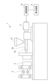
- FIG. 1 is a schematic diagram showing a configuration of an injection molding machine according to a first embodiment.
- FIG. FIG. 2 is a perspective view showing a heater disposed in the cylinder according to the first embodiment.
- FIG. 2 is a functional block diagram of a control device for the injection molding machine according to the first embodiment.
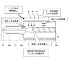
- FIG. 4 is a schematic diagram illustrating a heat balance during forming according to the first embodiment.
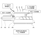
- FIG. 4 is a schematic diagram illustrating a heat balance when molding is stopped in the first embodiment.
- FIG. 11 is a schematic diagram illustrating a heat balance during forming according to the second embodiment.
- FIG. 11 is a schematic diagram illustrating the heat balance when molding is stopped in the second embodiment.
- FIG. 11 is a functional block diagram of a control device for an injection molding machine according to a second embodiment.
- 10 is a flowchart showing an example of a processing flow by a control device of an injection molding machine according to a second embodiment.
- FIG. 11 is a functional block diagram of a control device for an injection molding machine according to a third embodiment.
- Fig. 1 is a schematic diagram showing the configuration of an injection molding machine 1 according to the first embodiment.
- Fig. 2 is a perspective view showing heaters 24a to 24d arranged in a cylinder 22 of the injection molding machine 1 according to the first embodiment.
- the injection molding machine 1 of this embodiment includes an injection section 2, a mold clamping section 3, a control device 10, and a display device 6.
- the injection unit 2 is an injection device that includes a hopper 21, a cylinder 22, a screw 23, and a cooling jacket 26.
- the cylinder 22 is, for example, a cylindrical body. Resin stored in the hopper 21 is supplied to the cylinder 22.
- the screw 23 is disposed inside the cylinder 22, and transports the resin to the tip of the cylinder 22 by rotating.
- the cooling jacket 26 is a device that cools the inside of the cylinder 22 (for example, the part on the root side inside the cylinder 22), and cooling water circulates through it.
- heaters 24a to 24d are arranged, for example, in a plurality of positions along the axial direction of cylinder 22. Specifically, heaters 24a to 24d are arranged in a plurality of positions from nozzle portion 25 at the axial tip of cylinder 22 to the base end. Note that there is no particular limit to the number of heaters 24a to 24d.
- heaters 24a to 24d are arranged along the axial direction to cover the outer periphery of the cylinder 22.
- Heater 24a is one of the tip heaters arranged in the nozzle portion 25.
- Heaters 24b to 24d are located upstream of the nozzle portion 25 in the pellet conveying direction.
- Heater 24b is one of the tip heaters located closest to the nozzle portion 25.
- Heater 24d is located farthest from the nozzle portion 25, and heater 24c is located between heaters 24b and 24d.
- the pellets are melted by heating the cylinder 22 with the heaters 24a to 24d.
- the molten pellets are transported by the screw 23 to the nozzle portion 25 and injected into the mold 5.
- the mold clamping unit 3 is a device that clamps the mold 5. A molded product is formed by clamping the mold 5 with the mold clamping unit 3.
- FIG. 3 is a functional block diagram of the control device 10 of the injection molding machine 1 according to the first embodiment.
- the control device 10 of the injection molding machine 1 according to the first embodiment is configured using a computer equipped with memories such as a ROM (read only memory) and a RAM (random access memory), a CPU (control processing unit), and a communication control unit, which are connected to each other via a bus, for example.
- memories such as a ROM (read only memory) and a RAM (random access memory), a CPU (control processing unit), and a communication control unit, which are connected to each other via a bus, for example.
- the functions and operations of each functional unit of the control device 10 described below are achieved by the cooperation of the CPU and memory mounted on the computer, and the control program stored in the memory.
- the control device 10 has, as functional units, an operation information acquisition unit 11, a characteristic information acquisition unit 12, a heater heat generation amount calculation unit 13, a heater heat transfer amount calculation unit 14, a shear heat generation amount calculation unit 15, a plasticization index calculation unit 16, and an output unit 20.
- the operation information acquisition unit 11 acquires operation information related to the operation of the heaters 24a to 24d.
- the operation information related to the heaters 24a to 24d is the operation rate of each of the heaters 24a to 24d.
- the operation rate is an index of the operation state, for example, indicated as 0 to 100%.
- the operation rate is determined, for example, based on the output, such as the voltage, of the heaters 24a to 24d.
- the operation information acquisition unit 11 also acquires information related to the operation of the screw 23 as operation information.
- the information related to the operation of the screw 23 is, for example, the motor current during metering, the rotational angular velocity of the screw 23, etc.
- the characteristic information acquisition unit 12 acquires characteristic information indicating the characteristics of the injection molding machine 1.
- the characteristic information is, for example, the capacity of the heaters 24a to 24d.
- the capacity of the heaters 24a to 24d here is a rated capacity of 1500 W at 200 V.
- the characteristic information acquisition unit 12 also acquires information about the characteristics of the screw 23 as characteristic information.
- the information about the characteristics of the screw 23 is, for example, the reduction ratio between the screw 23 and the motor that rotates the screw 23, the mechanical efficiency, the torque constant of the rotating motor that rotates the screw 23, etc.
- the heater heat generation amount calculation unit 13 calculates the heat generation amount of the heaters 24a to 24d based on the acquired operation information and characteristic information. For example, the heater heat generation amount calculation unit 13 calculates the heat generation amount of each heater 24a to 24d for a predetermined time while the cylinder 22 is maintained at a preset temperature. The heater heat generation amount calculation unit 13 may calculate the heat generation amount by making corrections based on the difference between the rated voltage of the heaters 24a to 24d and the actual power supply voltage of the injection molding machine 1.
- the amount of heat generated can be calculated, for example, by the following formula (1).
- E Hi represents the amount of heat generated
- t 1 represents the calculation start time
- t 2 represents the calculation end time
- W i represents the heater capacity
- r i represents the heater operation rate.
- the heater heat transfer amount calculation unit 14 calculates the amount of heat transfer from each of the heaters 24a to 24d to the resin based on the calculation result of the heater heat transfer amount calculation unit 13. An example of a method for calculating the amount of heat transfer by the heater heat transfer amount calculation unit 14 will be described.
- the amount of heat transfer from the heaters 24a to 24d to the resin is E Ti .
- the amount of heat transfer E Ti can be calculated from the difference between the amount of heat generated when molding is being performed E Hi and the amount of heat generated when molding is stopped E' Hi .
- Fig. 4 is a schematic diagram for explaining the heat balance during molding.
- Fig. 5 is a schematic diagram for explaining the heat balance when molding is stopped.
- the heat generation amount E Hi during molding to maintain the cylinder 22 at the set temperature can be considered as the sum of the heat transfer amount E Ti and various heat dissipation.
- the various heat dissipation is the sum of the heat amount applied to the heater 24b, the heat transfer amount to the front (the nozzle portion 25 side), the heat transfer amount to the rear (the opposite side of the nozzle portion 25), and the heat dissipation from the surface of the heater 24b.
- the screw 23 is stopped inside the cylinder 22, and the resin is not flowing and remains in a stagnant state.
- the resin temperature can be considered to be the same as the temperature of the cylinder 22, so the heat generated by the heater 24b is not transferred to the resin. Therefore, as shown in Fig. 5, the heat generation amount E'Hi when molding is stopped and the cylinder 22 is maintained at the set temperature can be considered to be equal to the various heat dissipations.
- the heat transfer amount ETi can be obtained by subtracting the heat generation amount E'Hi from the heat generation amount EHi , whereby the various heat dissipations are offset.
- the heater heat transfer amount calculation unit 14 of this embodiment calculates the total heat transfer amount, which is the sum of the heat transfer amounts of the heaters 24a to 24d, based on the above-mentioned concept.
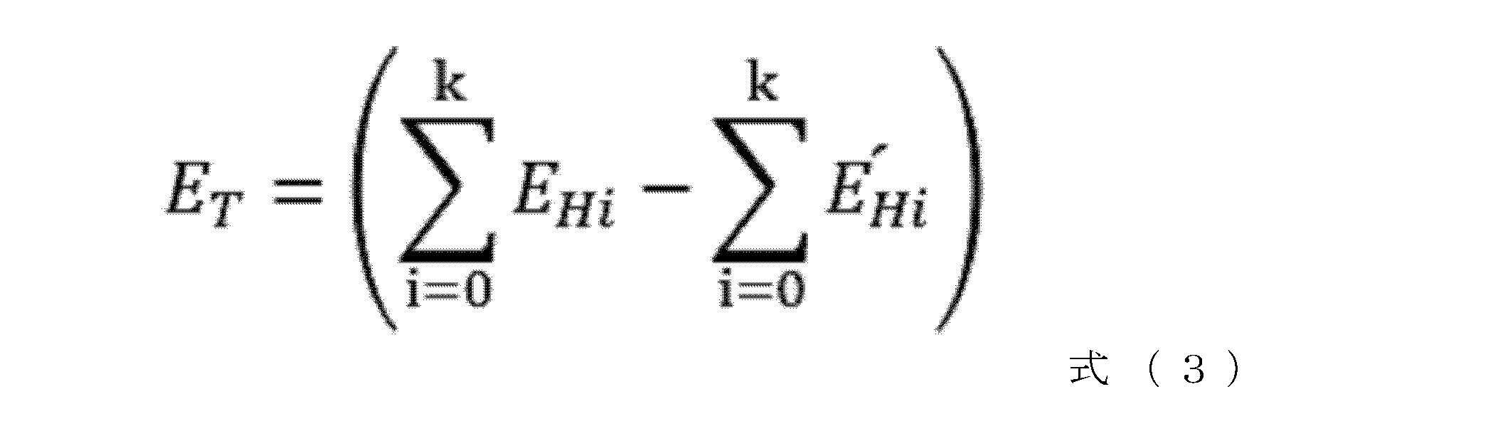
- the sum of the heat transfer amounts from the heaters 24a to 24d to the resin is taken as the total heat transfer amount E T.
- E Hi the total heat transfer amount of each of the heaters 24a to 24d when molding is being performed
- E' Hi the total heat transfer amount can be expressed as in the following formula (3).
- i 0, 1, 2, ... k.
- the shear heat generation amount calculation unit 15 calculates the amount of shear heat generation caused by the rotation of the screw 23 based on the operation information acquired by the operation information acquisition unit 11 and the characteristic information acquired by the characteristic information acquisition unit 12.
- the shear heat generation amount is the amount of heat generated due to shear caused by the rotation of the screw 23.
- the shear heat generation amount can be calculated, for example, by the following formula (4).
- E S represents the shear heat generation amount of the screw
- K T represents the torque constant of the rotary motor that rotates the screw
- r represents the motor current during metering
- R represents the reduction ratio between the motor and the screw
- ⁇ represents the rotational angular velocity of the screw
- ⁇ represents the mechanical efficiency.
- the plasticization index calculation unit 16 calculates the total amount of heat transfer throughout the cylinder 22, and uses this to calculate indices related to plasticization, such as the overall plasticization state (quality) inside the cylinder 22 and energy efficiency.
- Fig. 6 is a schematic diagram illustrating the energy balance around the cylinder 22. As shown in Fig. 6, if the total amount of heat received by the resin material is E M , the total amount of heat E M can be expressed by the following formula (5) using the total amount of heat transfer E T and the amount of shear heat generation E S.
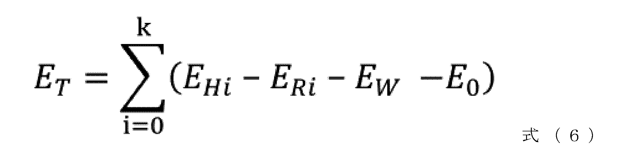
- the amount of heat dissipated to the surrounding environment can be considered as the amount of heat dissipated to the air E Ri , the amount of heat E W absorbed by the cooling water flowing inside the cooling jacket 26, and the amount of heat E 0 dissipated to the machine body.
- the heat generation amount of each heater 24a to 24d is E Hi
- the total amount of heat transfer E T of all heaters 24a to 24d can be expressed by the following formula (6).
- E T :E S is the ratio of the amount of heat transfer and the amount of shear heat generation, which are the breakdown of the total amount of heat E M received by the resin material. Under conditions where the ratio is such that the amount of heat transfer is predominant, the energy efficiency is poor but the melting quality of the resin is good. On the other hand, under conditions where the ratio is such that the amount of shear heat generation is predominant, the energy efficiency is good but the melting quality is poor. If the total amount of heat transfer E T from the heaters 24a to 24d to the resin can be calculated, the ratio of this amount of heat transfer and the amount of shear heat generation can also be calculated. Therefore, E T :E S is an index representing the plasticization state.
- the plasticization index calculation unit 16 of the present embodiment calculates the ratio of the heat transfer amount to the shear heat generation amount ( ET : ES ) as an index related to plasticization based on information on the total heat transfer amount ET calculated by the heater heat transfer amount calculation unit 14 and the shear heat generation amount ES calculated by the shear heat generation amount calculation unit 15.
- the plasticization index calculation unit 16 may also calculate the energy efficiency related to plasticization using the heater heat transfer amount.
- the output unit 20 will be described.
- the output unit 20 outputs the index related to plasticization calculated by the plasticization index calculation unit 16.
- a process is executed to display the "ratio of heat transfer amount and shear heat generation amount ( ET : ES )" and "energy efficiency" which are the calculation results of the plasticization index calculation unit 16 on the display device 6 of the injection molding machine 1.
- the output unit 20 may be configured to output the judgment result of the plasticization index calculation unit 16 to an external computer connected to the injection molding machine 1 different from the display device 6 of the injection molding machine 1.
- the display device 6 is, for example, an output device such as a liquid crystal display or a touch panel display. Note that instead of the display device 6, the calculation results of the plasticization index calculation unit 16 may be output by a sound output device that outputs sound.
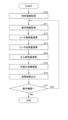
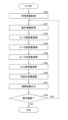
- Fig. 7 is a flow chart showing an example of a process flow by the control device 10 of the injection molding machine 1 according to the first embodiment.
- the characteristic information acquisition unit 12 acquires characteristic information indicating the characteristics of the injection molding machine 1 (step S10), and the operation information acquisition unit 11 acquires the operating rates related to the operations of the heaters 24 a to 24 d as operation information (step S11).
- the operation information and characteristic information are acquired, for example, from various sensors, a storage unit (not shown) of the control device 10, an external computer (not shown), etc.
- the heater heat generation amount calculation unit 13 calculates the heat generation amount of the heaters 24a to 24d based on the acquired operation information and characteristic information (step S12). The heater heat generation amount calculation unit 13 calculates the heat generation amount of each of the heaters 24a to 24d when the cylinder 22 is maintained at a predetermined set temperature based on, for example, the operation rate of the heaters 24a to 24d and the capacity of the heaters 24a to 24d.
- the heater heat transfer amount calculation unit 14 calculates the amount of heat transfer from the heaters 24a to 24d to the resin (step S13).
- the heater heat transfer amount calculation unit 14 for example, substitutes the heat generation amount E Hi of the heaters 24a to 24d when molding is in progress and the heat generation amount E ' Hi of the heaters 24a to 24d when molding is stopped into the above formula (2) to calculate the heat transfer amount E Ti from the heaters 24a to 24d to the resin.
- the heater heat transfer amount calculation unit 14 calculates the total heat transfer amount E T of all the heaters 24a to 24d as shown in formula (3).
- the shear heat generation calculation unit 15 obtains the shear heat generation amount based on the motion information obtained by the motion information acquisition unit 11 and the characteristic information obtained by the characteristic information acquisition unit 12 (step S14).
- the plasticization index calculation unit 16 calculates an index representing the plasticization state based on the total heat transfer amount E T calculated by the heater heat transfer amount calculation unit 14 and the shear heat generation amount E S calculated by the shear heat generation amount calculation unit 15 (step S15).
- the output unit 20 When the calculation result by the plasticization index calculation unit 16 is output, the output unit 20 outputs the calculation result (step S16).
- the output unit 20 executes a process to display the calculation result by the plasticization index calculation unit 16 on the display device 6 as a numerical value, a letter, a symbol, a graph, a picture, or a combination thereof, for example.
- step S15 After the processing by the output unit 20 in step S15, if the molding process is to be continued, the control device 10 returns the process to step S11 and executes the processes from step S11 onwards again (step S17; Yes). On the other hand, if the control device 10 detects that the molding process has been stopped, it executes a process to stop molding and ends the flow (step S17; No). Note that the continuation or stop of the molding process is determined by the control device 10 based on, for example, the user's operation or whether the plasticization state satisfies predetermined conditions.
- the control device 10 for the injection molding machine 1 provides the following effects. That is, the injection molding machine 1 comprises a cylinder 22, heaters 24a to 24d arranged around the cylinder 22, and a screw 23 arranged inside the cylinder 22.
- the control device 10 for the injection molding machine 1 comprises an operation information acquisition unit 11 that acquires operation information relating to the operation of the heaters 24a to 24d and the screw 23, a characteristic information acquisition unit 12 that acquires characteristic information relating to the characteristics of the injection molding machine 1, a heater heat generation amount calculation unit 13 that calculates the heat generation amounts of the heaters 24a to 24d based on the acquired operation information and characteristic information, and a heat generation amount calculation unit 14 that calculates the heat generation amounts of the heaters 24a to 24d when molding is performed with the cylinder 22 maintained at a predetermined set temperature and a heat generation amount calculation unit 15 that calculates the heat generation amount of the heaters 24a to 24d when molding is performed with the cylinder 22 maintained at a predetermined set temperature.
- the apparatus includes a heater heat transfer amount calculation unit 14 that calculates the amount of heat transfer from the heaters 24a to 24d to the resin based on the amount of heat generated by the heaters 24a to 24d when molding is stopped in the molding process, a shear heat generation amount calculation unit 15 that calculates the amount of shear heat generated by the rotation of the screw 23, a plasticization index calculation unit 16 that calculates an index related to plasticization based on the amount of heat transfer calculated by the heater heat transfer amount calculation unit 14 and the amount of shear heat generated by the shear heat generation amount calculation unit 15, and an output unit 20 that outputs the calculation result of the plasticization index calculation unit 16.
- a heater heat transfer amount calculation unit 14 that calculates the amount of heat transfer from the heaters 24a to 24d to the resin based on the amount of heat generated by the heaters 24a to 24d when molding is stopped in the molding process
- a shear heat generation amount calculation unit 15 that calculates the amount of shear heat generated by the rotation of the screw 23
- a plasticization index calculation unit 16 that calculate
- the index related to plasticization is output by the output unit 20, the user can accurately grasp the plasticization state of the resin without requiring a special sensor even during continuous molding. Additionally, the information output by the output unit 20 can be used to identify the cause of molding defects.
- the plasticization index calculation unit 16 calculates the ratio of the amount of heat transferred from the heaters 24a to 24d to the resin and the amount of shear heat generation as an index related to plasticization. This allows the user to grasp the plasticization quality of the resin from the ratio of the amount of heat transferred and the amount of shear heat generation. For example, if the heat transfer ratio is high, it can be seen that the energy efficiency is low but the molten state of the resin is good. On the other hand, conversely, if the shear ratio is high, it can be seen that the energy efficiency is high but the molten state cannot be said to be good.
- the operating rate indicating the operating state of the heaters 24a to 24d differs between when molding is in progress and when molding is stopped. If the operating rates of the heaters 24a to 24d differ, the surface temperatures of the heaters 24a to 24d differ, and the amount of heat dissipated from the surfaces of the heaters 24a to 24d also differ. For example, the amount of heat dissipated E Ri during molding as shown in Fig. 8 differs from the amount of heat dissipated E' Ri during molding stop as shown in Fig. 9 (amount of heat dissipated E Ri ⁇ amount of heat dissipated E' Ri ). Therefore, if the difference between the amount of heat dissipated by the heaters 24a to 24d during molding and when molding is stopped is corrected, the amount of heat transfer can be calculated more accurately.
- the amount of heat generated during molding EHi can be considered to be the sum of the amount of heat transfer ETi , the amount of heat radiation ERi , and other heat radiation excluding the amount of heat radiation ERi from various types of heat radiation.
- the other heat radiation is the amount of heat transferred to the heater 24b toward the front (the nozzle portion 25 side) and the amount of heat transferred to the rear (the opposite side of the nozzle portion 25).
- Heat dissipation from the heater surface can be divided into two types, convection and radiation, and the amount of heat dissipation can be calculated by adding them together.
- the amount of heat dissipation is calculated using the heater surface temperature and ambient temperature acquired by the operation information acquisition unit 11, as well as the heater surface area, heat transfer coefficient, emissivity, and Stefan-Boltzmann coefficient acquired by the characteristic information acquisition unit 12.
- the cylinder 22 may be assumed to have a simple cylindrical shape.
- the ambient temperature and heater surface temperature are acquired, for example, by using the detection value of a temperature sensor (not shown) or by estimating using a predetermined function.
- the amount of heater convection heat dissipation can be calculated, for example, using the following formula (7).
- the amount of heater radiation heat dissipation can be calculated, for example, using the following formula (8).
- E rc i represents the amount of heater convection heat dissipation
- T Hi represents the heater surface temperature
- T C represents the ambient temperature
- Ai represents the heater surface area
- h represents the heat transfer coefficient
- E Rri represents the amount of heater radiation heat dissipation
- ⁇ represents the emissivity
- ⁇ represents the Stefan-Boltzmann coefficient.
- the amount of heat transfer from a heater 24 to adjacent zones such as the front or rear in the axial direction of the cylinder 22 hardly changes if the set temperature of the cylinder 22 is the same.
- the amount of heat transfer to the zone of heater 24a or the zone of heater 24c adjacent to the zone of heater 24b does not change. Therefore, it can be considered that the other heat dissipation excluding E Ri from the various heat dissipation during molding is equal to the other heat dissipation excluding E' Ri from the various heat dissipation when molding is stopped.
- the heat transfer amount is calculated using the following formula (9).
- the total heat transfer amount which is the sum of the heat transfer amounts of the heaters 24a to 24d.
- the total heat transfer amount E T is the sum of the heat transfer amounts from the heaters 24a to 24d to the resin.
- the total heat transfer amount can be expressed as the following formula (10).
- FIG. 10 is a functional block diagram of the control device 10a of the injection molding machine 1 according to the second embodiment.
- FIG. 11 is a flowchart showing an example of the processing flow by the control device 10a of the injection molding machine 1 according to the second embodiment.
- control device 10a according to the second embodiment is different from the control device 10 of the injection molding machine 1 according to the first embodiment in that it further includes a heater heat radiation amount calculation unit 17 and in the process for calculating the heat transfer amount E Ti , but the other configurations are common to the first embodiment.
- the characteristic information acquisition unit 12 acquires, as characteristic information, the capacities of the heaters 24 a to 24 d, information on the screw 23, as well as the shapes of the heaters 24 a to 24 d and constants related to the heat dissipation of the heaters 24 a to 24 d (step S20).
- the operation information acquisition unit 11 also acquires the heater surface temperature and the ambient temperature as operation information, in addition to the operating rates of the heaters 24a to 24d and information on the screw 23 (step S21).
- Constants related to heat dissipation include, for example, the heat transfer coefficient, the emissivity, the Stefan-Boltzmann coefficient, etc.
- the heater heat generation amount calculation unit 13 calculates the heat generation amounts of the heaters 24a to 24d based on the acquired operation information and characteristic information (step S22).
- the heater heat dissipation amount calculation unit 17 calculates the heat dissipation amount of each heater 24a to 24d based on the operation information acquired by the operation information acquisition unit 11 and the characteristic information acquired by the characteristic information acquisition unit 12 (step S23).
- the heat dissipation amount of each heater 24a to 24d is the heat dissipation amount when the cylinder 22 is maintained at a predetermined set temperature.
- the heater heat transfer amount calculation unit 14 calculates the heat transfer amount E Ti from the heaters 24a to 24d to the resin (step S24).
- the heater heat transfer amount calculation unit 14 calculates the heat transfer amount E Ti from the heaters 24a to 24d to the resin by substituting, for example, the heat generation amount E Hi and the heat radiation amount E Ri of the heaters 24a to 24d when molding is being performed, and the heat generation amount E' Hi and the heat radiation amount E' Ri of the heaters 24a to 24d when molding is stopped, into the above formula (9). Then, the heater heat transfer amount calculation unit 14 uses the calculation results of each heater 24a to 24d to calculate the total heat transfer amount E T of all the heaters 24a to 24d as shown in formula (10).
- the shear heat generation calculation unit 15 obtains the shear heat generation amount based on the motion information obtained by the motion information acquisition unit 11 and the characteristic information obtained by the characteristic information acquisition unit 12 (step S25).
- the plasticization index calculation unit 16 calculates an index representing the plasticization state based on the total heat transfer amount E T calculated by the heater heat transfer amount calculation unit 14 and the shear heat generation amount E S calculated by the shear heat generation amount calculation unit 15 (step S26).
- the output unit 20 performs output processing based on the calculation result of the plasticization index calculation unit 16 (step S27).
- the processing of step S28 is the same as the processing of step S17 in FIG. 7.
- control device 10a of the injection molding machine 1 provides the following effects.
- the control device 10a of the injection molding machine 1 further includes a heater heat dissipation calculation unit 17 that calculates the amount of heat dissipation of the heaters 24a to 24d based on the operation information and characteristic information, and the heater heat transfer calculation unit 14 calculates the amount of heat transfer from the heaters 24a to 24d to the resin based on the amounts of heat generated by the heaters 24a to 24d and the amount of heat dissipation calculated by the heater heat transfer calculation unit 17 when molding is in progress, and the amounts of heat generated by the heaters 24a to 24d and the amount of heat dissipation calculated by the heater heat transfer calculation unit 17 when molding is stopped.
- Fig. 12 is a functional block diagram of a control device 10b of an injection molding machine 1 according to a third embodiment.
- the control device 10b according to the third embodiment is different from the control device 10 of the injection molding machine 1 according to the first embodiment in that it further includes a cooling water heat amount calculation unit 18 and in the process for calculating the heat transfer amount E Ti , but the other configurations are the same as those of the first embodiment.
- the operation information acquisition unit 11 acquires the flow rate, inlet temperature, and outlet temperature of the cooling water in the cooling jacket 26 as operation information, in addition to the operating rates of the heaters 24a to 24d.
- the characteristic information acquisition unit 12 acquires the capacity of the heaters 24a to 24d as well as the density and specific heat of the cooling water flowing through the cooling jacket as characteristic information.
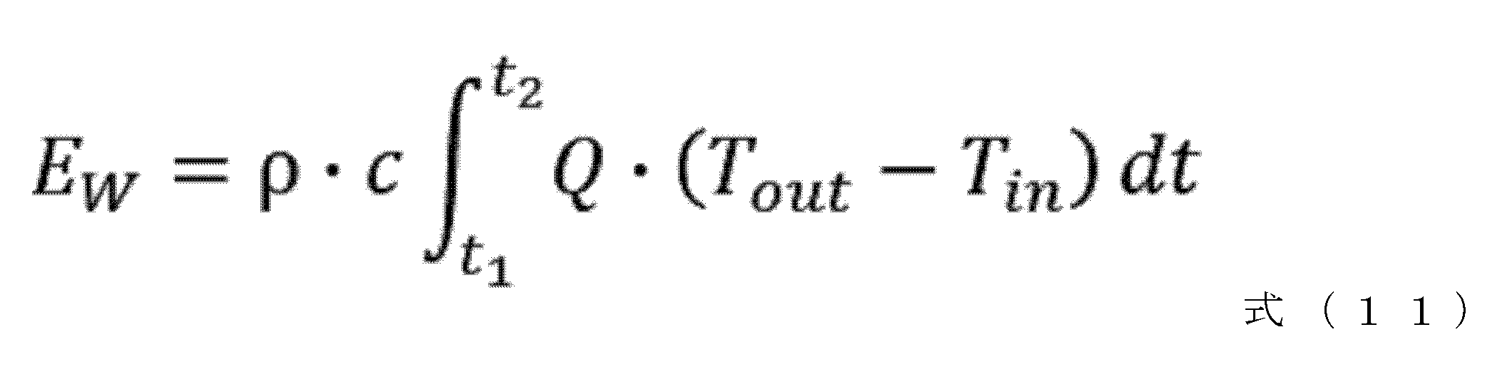
- the coolant heat quantity calculation unit 18 calculates the amount of heat lost by the coolant as an increase in the internal energy of the coolant based on the operation information acquired by the operation information acquisition unit 11 and the characteristic information acquired by the characteristic information acquisition unit 12. An example of a method for calculating the amount of heat lost by the coolant using the coolant heat quantity calculation unit 18 will be described.
- the amount of heat lost by the coolant can be calculated, for example, by the following formula (11).
- E W represents the amount of heat lost by the coolant
- ⁇ represents the density of the coolant
- c represents the specific heat of the coolant
- Q represents the flow rate of the coolant
- T in represents the inlet temperature of the coolant
- T out represents the outlet temperature of the coolant.
- the heater heat transfer amount calculation unit 14 calculates the amount of heat transfer from the heaters 24a to 24d to the resin based on the total heat generation amount calculated by the heater heat generation amount calculation unit 13 and the amount of heat lost by the cooling water calculated by the cooling water heat amount calculation unit 18.
- the amount of heat generated by each of the heaters 24a to 24d when molding is being performed with the cylinder 22 maintained at a predetermined set temperature is defined as E Hi
- the amount of heat lost by the cooling water is defined as E w
- the amount of heat generated by each of the heaters 24a to 24d when molding is stopped with the cylinder 22 maintained at a predetermined set temperature is defined as E' Hi
- the amount of heat lost by the cooling water is defined as E' w .
- the total amount of heat transfer E T can be calculated using the following formula (12).
- control device 10 of the injection molding machine 1 provides the following effects.
- the control device 10 further includes a cooling water heat amount calculation unit 18 that calculates the amount of heat lost to the cooling water in the cooling jacket 26 based on operation information and characteristic information including information related to the cooling jacket 26 provided in the injection molding machine 1, and the heater heat transfer amount calculation unit 14 calculates the amount of heat transferred from the heaters 24a to 24d to the resin based on the amounts of heat generated by the heaters 24a to 24d during molding and the amount of heat lost to the cooling water calculated by the cooling water heat amount calculation unit 18, and the amounts of heat generated by the heaters 24a to 24d during molding stop and the amount of heat lost to the cooling water calculated by the cooling water heat amount calculation unit 18.
- the configuration of the third embodiment corrects the difference in the amount of heat of the cooling water between when molding is in progress and when molding is stopped, making it possible to calculate the amount of heat transfer more accurately.
- the control device 10 according to the fourth embodiment has a common configuration with the control device 10 of the injection molding machine 1 according to the first embodiment.
- the calculation process of the plasticization index calculation unit 16 is different from that in the first embodiment.
- the plasticization index calculation unit 16 calculates the ratio between the sum of the heat generation amount and the shear heat generation amount of the heaters 24a to 24d and the sum of the heater heat transfer amount and the shear heat generation amount. Furthermore, the plasticization index calculation unit 16 further calculates the ratio between the heat generation amount and the heat transfer amount of the heaters 24a to 24d to obtain the energy efficiency.
- the output unit 20 outputs to the display device 6 the ratio of the sum of the heat generation amount and the shear heat generation amount of the heaters 24a to 24d and the sum of the heater heat transfer amount and the shear heat generation amount, as well as the ratio of the heat generation amount and the heat transfer amount of the heaters 24a to 24d as an index related to plasticization.
- the plasticization index calculation unit 16 calculates the ratio between the sum of the heat generation amount and the shear heat generation amount of the heaters 24a to 24d and the sum of the heat transfer amount and the shear heat generation amount of the heaters 24a to 24d as an index related to plasticization. This calculates the plasticization energy efficiency, which indicates how much of the energy input by the injection molding machine 1 to plasticize the resin is transferred to the resin. Therefore, the user can use the plasticization energy efficiency to determine whether the efficiency is good or bad and then determine the molding conditions.
- the plasticization index calculation unit 16 calculates the ratio between the heat generation amount of the heaters 24a to 24d and the heat transfer amount of the heaters 24a to 24d as an index related to plasticization. This calculates the energy efficiency of the heaters 24a to 24d, which indicates how much of the heat generation amount of the heaters is transferred to the resin. Therefore, the user can use the energy efficiency of the heaters 24a to 24d to determine the efficiency and then determine the molding conditions.
- the control device 10 according to the fifth embodiment has a common configuration with the control device 10 of the injection molding machine 1 according to the first embodiment.
- the method of calculating the heat transfer amount by the heater heat transfer amount calculation unit 14 is different from that in the first embodiment.
- the operation information acquisition unit 11 acquires the set temperature of each control point of the cylinder 22 as operation information.
- the actual temperature at each control point may also be acquired.
- the characteristic information acquisition unit 12 acquires a preset regression equation together with the capacity of the heaters 24a to 24d as characteristic information.
- the regression equation is acquired, for example, from a memory unit (not shown) of the control device 10.
- the heater heat transfer amount calculation unit 14 calculates the amount of heat generated by the heaters 24a to 24d to maintain the cylinder 22 at the set temperature without using the calculation results of the heater heat generation amount calculation unit 13.
- the amount of heat generated in the molding stopped state is the amount of heat required to maintain the cylinder 22 at the set temperature. Therefore, the amount of heat transfer in the molding stopped state can be uniquely determined by the set temperature of the control point of the cylinder 22 in the molding stopped state.
- the heat generation amount is estimated using a regression equation that shows the relationship between the set temperature of the cylinder 22 obtained in advance and the heat generation amount. This eliminates the need to actually measure the heat generation amount each time the set temperature of the cylinder 22 changes. Note that when the set temperatures of adjacent heaters 24a to 24d are different, heat moves in the axial direction, so it is desirable to use the values of not only the target heater but also the adjacent heaters as explanatory variables in the regression equation. Furthermore, in the fifth embodiment, the ambient temperature around the cylinder 22 may also be added as an explanatory variable.
- control device 10 has a common configuration with the control device 10a of the injection molding machine 1 according to the second embodiment.
- the method of calculating the heat transfer amount by the heater heat transfer amount calculation unit 14 is different from that in the first embodiment.
- the operation information acquisition unit 11 acquires the set temperature of each control point of the cylinder 22 as operation information.
- the actual temperature at each control point may also be acquired.
- the characteristic information acquisition unit 12 acquires a preset regression equation together with the capacity of the heaters 24a to 24d as characteristic information.
- the regression equation is acquired, for example, from a memory unit (not shown) of the control device 10.
- the surface temperatures of the heaters 24a to 24d in the molding stopped state are uniquely determined by the set temperature of the cylinder. Therefore, in the ninth embodiment, the surface temperatures of the heaters 24a to 24d are estimated based on a regression equation that shows the relationship between the temperature of the cylinder 22 and the surface temperatures of the heaters 24a to 24d, and the amount of heat dissipation in the molding stopped state is calculated. This eliminates the need to actually measure the amount of heat dissipation each time the set temperature of the cylinder 22 changes.
- the ambient temperature around the cylinder may be added as an explanatory variable of the regression equation.
- a control device (10, 10a, 10b) for an injection molding machine (1) including a cylinder (22), heaters (24a to 24d) disposed around the cylinder (22), and a screw (23) disposed inside the cylinder (22), an operation information acquisition unit (11) that acquires operation information related to the operation of the heaters (24a to 24d) and the screw (23); a characteristic information acquisition unit (12) that acquires characteristic information related to the characteristics of the injection molding machine (1); a heater heat generation amount calculation unit (13) that calculates the heat generation amount of the heaters (24a to 24d) based on the acquired operation information and characteristic information; a heater heat transfer amount calculation unit (14) for calculating an amount of heat transfer from the heaters (24a to 24d) to a resin based on the amount of heat generated by the heaters (24a to 24d) during molding in a state in which the cylinder (22) is maintained at a predetermined set temperature, and the amount of heat
- the control device (10, 10a, 10b) of the injection molding machine (1) further comprises a heater heat radiation amount calculation unit (17) that calculates a heat radiation amount of the heater (24a to 24d) based on the operation information and the characteristic information,
- the heater heat transfer amount calculation unit (14) The amount of heat transferred from the heaters (24a to 24d) to the resin is calculated based on the amount of heat generated by the heaters (24a to 24d) during molding and the amount of heat dissipation calculated by the heater heat dissipation calculation unit (17), and the amount of heat generated by the heaters (24a to 24d) and the amount of heat dissipation calculated by the heater heat dissipation calculation unit (17) when molding is stopped.
- the control device (10, 10a, 10b) of the injection molding machine (1) further comprises a cooling water heat amount calculation unit (18) that calculates the amount of heat taken away by the cooling water of the cooling jacket based on the operation information and the characteristic information, the operation information including information about the cooling jacket of the injection molding machine (1),
- the heater heat transfer amount calculation unit (14) The amount of heat transferred from the heaters (24a to 24d) to the resin is calculated based on the amount of heat generated by the heaters (24a to 24d) during molding and the amount of heat removed by the cooling water calculated by the cooling water heat amount calculation unit (18), and the amount of heat generated by the heaters (24a to 24d) and the amount of heat removed by the cooling water calculated by the cooling water heat amount calculation unit (18) when molding is stopped.
- the plasticization index calculation unit (16) In the control device (10, 10a, 10b) of the injection molding machine (1), the plasticization index calculation unit (16) The ratio of the amount of heat transferred from the heaters (24a to 24d) to the resin to the amount of shear heat generation is calculated as an index regarding the plasticization.
- the plasticization index calculation unit (16) In the control device (10, 10a, 10b) of the injection molding machine (1), the plasticization index calculation unit (16) The ratio of the sum of the heat generation amount of the heaters (24a to 24d) and the shear heat generation amount to the sum of the heater heat transfer amount and the shear heat generation amount is calculated as an index regarding the plasticization.
- the plasticization index calculation unit (16) In the control device (10, 10a, 10b) of the injection molding machine (1), the plasticization index calculation unit (16) The ratio between the heat generation amount of the heaters (24a to 24d) and the heat transfer amount of the heaters (24a to 24d) is calculated as an index regarding the plasticization.
Landscapes
- Engineering & Computer Science (AREA)
- Manufacturing & Machinery (AREA)
- Mechanical Engineering (AREA)
- Injection Moulding Of Plastics Or The Like (AREA)
Abstract
Description
図1は、第1実施形態に係る射出成形機1の構成を示す模式図である。図2は、第1実施形態に係る射出成形機1のシリンダ22に配置されるヒータ24a~24dを示す斜視図である。本実施形態の射出成形機1は、射出部2と、型締部3と、制御装置10と、表示装置6と、を備える。




第2実施形態では、ヒータ24a~24dの放熱量を考慮した制御を行う。図8及び図9を参照して第2実施形態の放熱量を考慮した熱収支について説明する。図8は第2実施形態の成形実行時の熱収支を説明する模式図であり、図9は第2実施形態の成形停止時の熱収支を説明する模式図である。


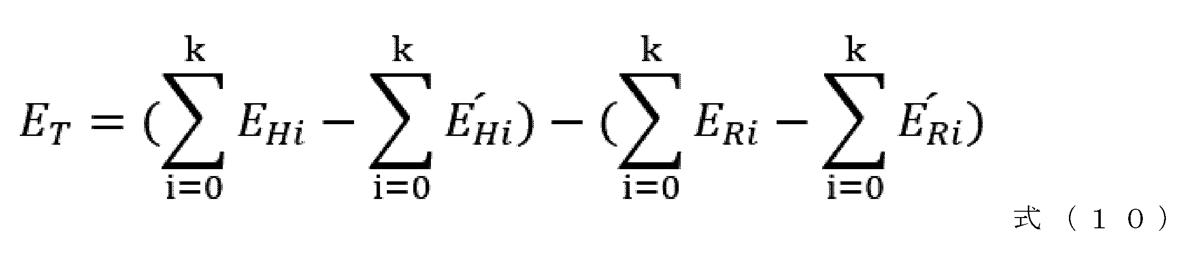
図12は、第3実施形態に係る射出成形機1の制御装置10bの機能ブロック図である。図12に示されるように、第3実施形態に係る制御装置10bは、第1実施形態に係る射出成形機1の制御装置10と比べて、冷却水熱量演算部18を更に備える点と、伝熱量ETiを演算するための処理と、が相違し、その他の構成は第1実施形態と共通である。

第4実施形態に係る制御装置10は、第1実施形態に係る射出成形機1の制御装置10と構成は共通である。第4実施形態では、可塑化指標演算部16の演算処理が第1実施形態と異なる。
第5実施形態に係る制御装置10は、第1実施形態に係る射出成形機1の制御装置10と構成は共通である。第5実施形態では、ヒータ伝熱量演算部14の伝熱量の演算方法が第1実施形態とは異なる。
第6実施形態に係る制御装置10は、第2実施形態に係る射出成形機1の制御装置10aと構成は共通である。第6実施形態では、ヒータ伝熱量演算部14の伝熱量の演算方法が第1実施形態とは異なる。
(付記1)
シリンダ(22)と、前記シリンダ(22)の周囲に配設されるヒータ(24a~24d)と、前記シリンダ(22)の内部に配置されるスクリュ(23)と、を備える射出成形機(1)の制御装置(10,10a,10b)であって、
前記ヒータ(24a~24d)及び前記スクリュ(23)の動作に関する動作情報を取得する動作情報取得部(11)と、
前記射出成形機(1)の特性に関する特性情報を取得する特性情報取得部(12)と、
取得された前記動作情報及び前記特性情報に基づいて、前記ヒータ(24a~24d)の発熱量を演算するヒータ発熱量演算部(13)と、
前記シリンダ(22)を所定の設定温度に維持した状態における成形実行時の前記ヒータ(24a~24d)の発熱量と、前記シリンダ(22)を所定の設定温度に維持した状態における成形停止時の前記ヒータ(24a~24d)の発熱量と、に基づいて前記ヒータ(24a~24d)から樹脂への伝熱量を演算するヒータ伝熱量演算部(14)と、
前記スクリュ(23)の回転によるせん断発熱量を演算するせん断発熱量演算部(15)と、
前記ヒータ伝熱量演算部(14)によって演算された伝熱量と、せん断発熱量演算部(15)によって演算されたせん断発熱量と、に基づいて、可塑化に関する指標を演算する可塑化指標演算部(16)と、
前記可塑化指標演算部(16)の演算結果を出力する出力部(20)と、を備える。
上記の射出成形機(1)の制御装置(10,10a,10b)において、前記動作情報及び前記特性情報に基づいて、前記ヒータ(24a~24d)の放熱量を演算するヒータ放熱量演算部(17)を更に備え、
前記ヒータ伝熱量演算部(14)は、
前記成形実行時における前記ヒータ(24a~24d)の発熱量及び前記ヒータ放熱量演算部(17)が演算した放熱量と、前記成形停止時における前記ヒータ(24a~24d)の発熱量と前記ヒータ放熱量演算部(17)が演算した放熱量と、に基づいて前記ヒータ(24a~24d)から樹脂への伝熱量を演算する。
上記の射出成形機(1)の制御装置(10,10a,10b)において、前記射出成形機(1)が備える冷却ジャケットに関する情報を含む前記動作情報及び前記特性情報に基づいて、前記冷却ジャケットの冷却水に奪われる熱量を演算する冷却水熱量演算部(18)を更に備え、
前記ヒータ伝熱量演算部(14)は、
前記成形実行時における前記ヒータ(24a~24d)の発熱量及び前記冷却水熱量演算部(18)が演算した冷却水に奪われる熱量と、前記成形停止時における前記ヒータ(24a~24d)の発熱量と前記冷却水熱量演算部(18)が演算した冷却水に奪われる熱量と、に基づいて前記ヒータ(24a~24d)から樹脂への伝熱量を演算する。
上記の射出成形機(1)の制御装置(10,10a,10b)において、前記可塑化指標演算部(16)は、
前記ヒータ(24a~24d)から樹脂への前記伝熱量と前記せん断発熱量の割合を前記可塑化に関する指標として演算する。
上記の射出成形機(1)の制御装置(10,10a,10b)において、前記可塑化指標演算部(16)は、
前記ヒータ(24a~24d)の発熱量と前記せん断発熱量の和と、前記ヒータ伝熱量と前記せん断発熱量の和と、の割合を前記可塑化に関する指標として演算する。
上記の射出成形機(1)の制御装置(10,10a,10b)において、前記可塑化指標演算部(16)は、
前記ヒータ(24a~24d)の発熱量と前記ヒータ(24a~24d)の伝熱量の割合を前記可塑化に関する指標として演算する。
10、10a、10b 制御装置
11 動作情報取得部
12 特性情報取得部
13 ヒータ発熱量演算部
14 ヒータ伝熱量演算部
15 せん断発熱量演算部
16 可塑化指標演算部
17 ヒータ放熱量演算部
18 冷却水熱量演算部
20 出力部
Claims (6)
- シリンダと、前記シリンダの周囲に配設されるヒータと、前記シリンダの内部に配置されるスクリュと、を備える射出成形機の制御装置であって、
前記ヒータ及び前記スクリュの動作に関する動作情報を取得する動作情報取得部と、
前記射出成形機の特性に関する特性情報を取得する特性情報取得部と、
取得された前記動作情報及び前記特性情報に基づいて、ヒータの発熱量を演算するヒータ発熱量演算部と、
前記シリンダを所定の設定温度に維持した状態における成形実行時の前記ヒータの発熱量と、前記シリンダを所定の設定温度に維持した状態における成形停止時の前記ヒータの発熱量と、に基づいて前記ヒータから樹脂への伝熱量を演算するヒータ伝熱量演算部と、
前記スクリュの回転によるせん断発熱量を演算するせん断発熱量演算部と、
前記ヒータ伝熱量演算部によって演算された伝熱量と、せん断発熱量演算部によって演算されたせん断発熱量と、に基づいて、可塑化に関する指標を演算する可塑化指標演算部と、
前記可塑化指標演算部の演算結果を出力する出力部と、
を備える射出成形機の制御装置。 - 前記動作情報及び前記特性情報に基づいて、前記ヒータの放熱量を演算するヒータ放熱量演算部を更に備え、
前記ヒータ伝熱量演算部は、
前記成形実行時における前記ヒータの発熱量及び前記ヒータ放熱量演算部が演算した放熱量と、前記成形停止時における前記ヒータの発熱量と前記ヒータ放熱量演算部が演算した放熱量と、に基づいて前記ヒータから樹脂への伝熱量を演算する、
請求項1に記載の射出成形機の制御装置。 - 前記射出成形機が備える冷却ジャケットに関する情報を含む前記動作情報及び前記特性情報に基づいて、前記冷却ジャケットの冷却水に奪われる熱量を演算する冷却水熱量演算部を更に備え、
前記ヒータ伝熱量演算部は、
前記成形実行時における前記ヒータの発熱量及び前記冷却水熱量演算部が演算した冷却水に奪われる熱量と、前記成形停止時における前記ヒータの発熱量と前記冷却水熱量演算部が演算した冷却水に奪われる熱量と、に基づいて前記ヒータから樹脂への伝熱量を演算する、
請求項1に記載の射出成形機の制御装置。 - 前記可塑化指標演算部は、
前記ヒータから樹脂への前記伝熱量と前記せん断発熱量の割合を前記可塑化に関する指標として演算する、
請求項1から3の何れかに記載の射出成形機の制御装置。 - 前記可塑化指標演算部は、
前記ヒータの発熱量と前記せん断発熱量の和と、前記ヒータ伝熱量と前記せん断発熱量の和と、の割合を前記可塑化に関する指標として演算する、
請求項1から3の何れかに記載の射出成形機の制御装置。 - 前記可塑化指標演算部は、
前記ヒータの発熱量と前記ヒータの伝熱量の割合を前記可塑化に関する指標として演算する、
請求項5に記載の射出成形機の制御装置。
Priority Applications (4)
| Application Number | Priority Date | Filing Date | Title |
|---|---|---|---|
| DE112022007720.4T DE112022007720T5 (de) | 2022-11-08 | 2022-11-08 | Vorrichtung zur Steuerung bzw. Regelung einer Spritzgießmaschine |
| CN202280101496.4A CN120129598A (zh) | 2022-11-08 | 2022-11-08 | 注射成型机的控制装置 |
| PCT/JP2022/041552 WO2024100765A1 (ja) | 2022-11-08 | 2022-11-08 | 射出成形機の制御装置 |
| JP2024556889A JPWO2024100765A1 (ja) | 2022-11-08 | 2022-11-08 |
Applications Claiming Priority (1)
| Application Number | Priority Date | Filing Date | Title |
|---|---|---|---|
| PCT/JP2022/041552 WO2024100765A1 (ja) | 2022-11-08 | 2022-11-08 | 射出成形機の制御装置 |
Publications (1)
| Publication Number | Publication Date |
|---|---|
| WO2024100765A1 true WO2024100765A1 (ja) | 2024-05-16 |
Family
ID=91032423
Family Applications (1)
| Application Number | Title | Priority Date | Filing Date |
|---|---|---|---|
| PCT/JP2022/041552 Ceased WO2024100765A1 (ja) | 2022-11-08 | 2022-11-08 | 射出成形機の制御装置 |
Country Status (4)
| Country | Link |
|---|---|
| JP (1) | JPWO2024100765A1 (ja) |
| CN (1) | CN120129598A (ja) |
| DE (1) | DE112022007720T5 (ja) |
| WO (1) | WO2024100765A1 (ja) |
Citations (2)
| Publication number | Priority date | Publication date | Assignee | Title |
|---|---|---|---|---|
| JP2001225372A (ja) * | 2000-02-16 | 2001-08-21 | Sumitomo Heavy Ind Ltd | 射出成形機の制御方法 |
| WO2021246524A1 (ja) * | 2020-06-05 | 2021-12-09 | ファナック株式会社 | 射出成形機の制御装置及びプログラム |
-
2022
- 2022-11-08 DE DE112022007720.4T patent/DE112022007720T5/de active Pending
- 2022-11-08 JP JP2024556889A patent/JPWO2024100765A1/ja active Pending
- 2022-11-08 WO PCT/JP2022/041552 patent/WO2024100765A1/ja not_active Ceased
- 2022-11-08 CN CN202280101496.4A patent/CN120129598A/zh active Pending
Patent Citations (2)
| Publication number | Priority date | Publication date | Assignee | Title |
|---|---|---|---|---|
| JP2001225372A (ja) * | 2000-02-16 | 2001-08-21 | Sumitomo Heavy Ind Ltd | 射出成形機の制御方法 |
| WO2021246524A1 (ja) * | 2020-06-05 | 2021-12-09 | ファナック株式会社 | 射出成形機の制御装置及びプログラム |
Also Published As
| Publication number | Publication date |
|---|---|
| DE112022007720T5 (de) | 2025-06-18 |
| JPWO2024100765A1 (ja) | 2024-05-16 |
| CN120129598A (zh) | 2025-06-10 |
Similar Documents
| Publication | Publication Date | Title |
|---|---|---|
| JP2020001183A (ja) | 射出成形機の成形支援装置 | |
| CN112297375A (zh) | 具有异常检测功能的注射成型机的温度控制装置 | |
| CN113453865B (zh) | 注塑成型机的成型辅助装置 | |
| JP2014069415A (ja) | 射出成形機 | |
| CN103317693B (zh) | 注射成型机 | |
| EP1084813A1 (en) | Excessive load detecting device for injection screw of injection molding machine | |
| Iwko et al. | Experimental study on energy consumption in the plasticizing unit of the injection molding machine | |
| WO2024100765A1 (ja) | 射出成形機の制御装置 | |
| KR100783657B1 (ko) | 사출성형기 및 사출성형방법 | |
| US7412301B1 (en) | Identifying quality molded article based on determination of plug blow | |
| JP5917340B2 (ja) | 射出成形機 | |
| JP3083757B2 (ja) | 樹脂可塑化用シリンダの温度制御方法および温度制御装置 | |
| JP7189395B1 (ja) | 演算装置及びプログラム | |
| US7218990B2 (en) | Control device for use in injection molding machine | |
| WO2024180691A1 (ja) | 射出成形機の制御装置及びプログラム | |
| CN115066324B (zh) | 注射成型辅助装置以及具备该注射成型辅助装置的注射成型机 | |
| JP5847670B2 (ja) | 射出成形機 | |
| CN114126825B (zh) | 注射成型机的成型辅助装置 | |
| TWI615262B (zh) | 判斷與調整塑料品質的方法 | |
| WO2024100763A1 (ja) | 射出成形機の制御装置 | |
| WO2021157253A1 (ja) | 射出成形支援装置及びそれを備えた射出成形機 | |
| JP2622925B2 (ja) | 射出成形方法 | |
| JP3838997B2 (ja) | 射出成形機の温度制御装置 | |
| US20230382011A1 (en) | Method for molding resin material mixed with pulverized material | |
| CN118043189A (zh) | 注射成型机的控制装置和程序 |
Legal Events
| Date | Code | Title | Description |
|---|---|---|---|
| 121 | Ep: the epo has been informed by wipo that ep was designated in this application |
Ref document number: 22965091 Country of ref document: EP Kind code of ref document: A1 |
|
| WWE | Wipo information: entry into national phase |
Ref document number: 202280101496.4 Country of ref document: CN |
|
| WWE | Wipo information: entry into national phase |
Ref document number: 112022007720 Country of ref document: DE |
|
| WWE | Wipo information: entry into national phase |
Ref document number: 2024556889 Country of ref document: JP |
|
| WWP | Wipo information: published in national office |
Ref document number: 202280101496.4 Country of ref document: CN |
|
| WWP | Wipo information: published in national office |
Ref document number: 112022007720 Country of ref document: DE |
|
| 122 | Ep: pct application non-entry in european phase |
Ref document number: 22965091 Country of ref document: EP Kind code of ref document: A1 |