WO2024095948A1 - 封止剤、硬化体、表示装置、表示装置の製造方法、太陽電池および組成物 - Google Patents
封止剤、硬化体、表示装置、表示装置の製造方法、太陽電池および組成物 Download PDFInfo
- Publication number
- WO2024095948A1 WO2024095948A1 PCT/JP2023/039038 JP2023039038W WO2024095948A1 WO 2024095948 A1 WO2024095948 A1 WO 2024095948A1 JP 2023039038 W JP2023039038 W JP 2023039038W WO 2024095948 A1 WO2024095948 A1 WO 2024095948A1
- Authority
- WO
- WIPO (PCT)
- Prior art keywords
- sealant
- mass
- viscosity
- less
- parts
- Prior art date
- Legal status (The legal status is an assumption and is not a legal conclusion. Google has not performed a legal analysis and makes no representation as to the accuracy of the status listed.)
- Ceased
Links
Classifications
-
- C—CHEMISTRY; METALLURGY
- C08—ORGANIC MACROMOLECULAR COMPOUNDS; THEIR PREPARATION OR CHEMICAL WORKING-UP; COMPOSITIONS BASED THEREON
- C08G—MACROMOLECULAR COMPOUNDS OBTAINED OTHERWISE THAN BY REACTIONS ONLY INVOLVING UNSATURATED CARBON-TO-CARBON BONDS
- C08G59/00—Polycondensates containing more than one epoxy group per molecule; Macromolecules obtained by polymerising compounds containing more than one epoxy group per molecule using curing agents or catalysts which react with the epoxy groups
- C08G59/18—Macromolecules obtained by polymerising compounds containing more than one epoxy group per molecule using curing agents or catalysts which react with the epoxy groups ; e.g. general methods of curing
-
- C—CHEMISTRY; METALLURGY
- C08—ORGANIC MACROMOLECULAR COMPOUNDS; THEIR PREPARATION OR CHEMICAL WORKING-UP; COMPOSITIONS BASED THEREON
- C08L—COMPOSITIONS OF MACROMOLECULAR COMPOUNDS
- C08L101/00—Compositions of unspecified macromolecular compounds
-
- C—CHEMISTRY; METALLURGY
- C08—ORGANIC MACROMOLECULAR COMPOUNDS; THEIR PREPARATION OR CHEMICAL WORKING-UP; COMPOSITIONS BASED THEREON
- C08L—COMPOSITIONS OF MACROMOLECULAR COMPOUNDS
- C08L63/00—Compositions of epoxy resins; Compositions of derivatives of epoxy resins
-
- C—CHEMISTRY; METALLURGY
- C09—DYES; PAINTS; POLISHES; NATURAL RESINS; ADHESIVES; COMPOSITIONS NOT OTHERWISE PROVIDED FOR; APPLICATIONS OF MATERIALS NOT OTHERWISE PROVIDED FOR
- C09K—MATERIALS FOR MISCELLANEOUS APPLICATIONS, NOT PROVIDED FOR ELSEWHERE
- C09K3/00—Materials not provided for elsewhere
- C09K3/10—Materials in mouldable or extrudable form for sealing or packing joints or covers
-
- H—ELECTRICITY
- H10—SEMICONDUCTOR DEVICES; ELECTRIC SOLID-STATE DEVICES NOT OTHERWISE PROVIDED FOR
- H10H—INORGANIC LIGHT-EMITTING SEMICONDUCTOR DEVICES HAVING POTENTIAL BARRIERS
- H10H20/00—Individual inorganic light-emitting semiconductor devices having potential barriers, e.g. light-emitting diodes [LED]
- H10H20/80—Constructional details
- H10H20/85—Packages
- H10H20/852—Encapsulations
-
- H—ELECTRICITY
- H10—SEMICONDUCTOR DEVICES; ELECTRIC SOLID-STATE DEVICES NOT OTHERWISE PROVIDED FOR
- H10K—ORGANIC ELECTRIC SOLID-STATE DEVICES
- H10K50/00—Organic light-emitting devices
- H10K50/80—Constructional details
- H10K50/84—Passivation; Containers; Encapsulations
- H10K50/844—Encapsulations
-
- H—ELECTRICITY
- H10—SEMICONDUCTOR DEVICES; ELECTRIC SOLID-STATE DEVICES NOT OTHERWISE PROVIDED FOR
- H10K—ORGANIC ELECTRIC SOLID-STATE DEVICES
- H10K59/00—Integrated devices, or assemblies of multiple devices, comprising at least one organic light-emitting element covered by group H10K50/00
- H10K59/10—OLED displays
-
- H—ELECTRICITY
- H10—SEMICONDUCTOR DEVICES; ELECTRIC SOLID-STATE DEVICES NOT OTHERWISE PROVIDED FOR
- H10K—ORGANIC ELECTRIC SOLID-STATE DEVICES
- H10K59/00—Integrated devices, or assemblies of multiple devices, comprising at least one organic light-emitting element covered by group H10K50/00
- H10K59/30—Devices specially adapted for multicolour light emission
- H10K59/38—Devices specially adapted for multicolour light emission comprising colour filters or colour changing media [CCM]
-
- H—ELECTRICITY
- H10—SEMICONDUCTOR DEVICES; ELECTRIC SOLID-STATE DEVICES NOT OTHERWISE PROVIDED FOR
- H10K—ORGANIC ELECTRIC SOLID-STATE DEVICES
- H10K85/00—Organic materials used in the body or electrodes of devices covered by this subclass
- H10K85/10—Organic polymers or oligomers
-
- H—ELECTRICITY
- H10—SEMICONDUCTOR DEVICES; ELECTRIC SOLID-STATE DEVICES NOT OTHERWISE PROVIDED FOR
- H10W—GENERIC PACKAGES, INTERCONNECTIONS, CONNECTORS OR OTHER CONSTRUCTIONAL DETAILS OF DEVICES COVERED BY CLASS H10
- H10W74/00—Encapsulations, e.g. protective coatings
- H10W74/10—Encapsulations, e.g. protective coatings characterised by their shape or disposition
-
- H—ELECTRICITY
- H10—SEMICONDUCTOR DEVICES; ELECTRIC SOLID-STATE DEVICES NOT OTHERWISE PROVIDED FOR
- H10W—GENERIC PACKAGES, INTERCONNECTIONS, CONNECTORS OR OTHER CONSTRUCTIONAL DETAILS OF DEVICES COVERED BY CLASS H10
- H10W74/00—Encapsulations, e.g. protective coatings
- H10W74/40—Encapsulations, e.g. protective coatings characterised by their materials
-
- H—ELECTRICITY
- H10—SEMICONDUCTOR DEVICES; ELECTRIC SOLID-STATE DEVICES NOT OTHERWISE PROVIDED FOR
- H10K—ORGANIC ELECTRIC SOLID-STATE DEVICES
- H10K2101/00—Properties of the organic materials covered by group H10K85/00
Definitions
- the present invention relates to a sealant, a cured product, a display device, a method for manufacturing a display device, a solar cell, and a composition.
- organic optical devices that use organic thin-film elements, such as organic electroluminescence (organic EL) display elements and organic thin-film solar cell elements.
- organic EL organic electroluminescence
- Organic thin-film elements are easy to fabricate using vacuum deposition, solution coating, etc., and therefore have excellent productivity.
- An organic electroluminescent display element has a thin film structure in which an organic light-emitting material layer is sandwiched between a pair of electrodes facing each other. Electrons are injected into this organic light-emitting material layer from one electrode and holes are injected from the other electrode, whereby the electrons and holes combine in the organic light-emitting material layer to emit light by themselves.
- Organic electroluminescent display elements have the advantages of having better visibility than liquid crystal display elements and the like that require a backlight, being able to be made thinner, and being able to be driven by a low DC voltage.
- organic electroluminescence display elements have a problem in that when the organic light-emitting material layer or electrodes are exposed to the outside air, their light-emitting characteristics deteriorate rapidly and their lifespan is shortened. Therefore, in order to improve the stability and durability of organic electroluminescence display elements, a sealing technique that isolates the organic light-emitting material layer and electrodes from moisture and oxygen in the air is essential for organic electroluminescence display elements.
- Examples of technologies related to sealants for organic electroluminescence elements include those described in Patent Document 1 (WO 2020/171186) and Patent Document 2 (WO 2020/067046).
- Patent Document 1 describes a composition comprising (A) a cationic polymerizable compound, (B) a photocationic polymerization initiator, and (C) one or more phosphoric acid compounds selected from the group consisting of phosphoric esters and phosphorous esters, wherein the cationic polymerizable compound (A) comprises (A-1) an alicyclic compound having an epoxy group and (A-2) an aromatic compound having an epoxy group, the aromatic compound having an epoxy group (A-2) comprises (A-2-1) a bisphenol A type epoxy resin and (A-2-2) a bisphenol F type epoxy resin, and the ratio A 1 /A 2 (mass ratio) of the content A 1 of the bisphenol A type epoxy resin (A-2-1) to the content A 2 of the bisphenol F type epoxy resin (A-2-2) is 0.2 to 5.
- the composition shows little increase in viscosity after irradiation with light, can be suitably used as a sealant for organic electroluminescence devices, and is unlikely to deteriorate the organic electro
- Patent Document 2 describes a sealant for organic electroluminescence display elements that contains a cationic polymerizable compound that contains an alicyclic compound having an epoxy group and an aromatic compound having an epoxy group, a photocationic polymerization initiator, and two or more types of cure retarders selected from the group consisting of phosphoric acid-based cure retarders, ether-based cure retarders, metal complex-based cure retarders, and nitroxy radical-based cure retarders, and that the phosphoric acid-based cure retarders are selected from the group consisting of phosphoric acid esters and phosphorous esters, has a sufficiently long pot life after light irradiation, exhibits a moderate increase in viscosity after light irradiation to facilitate lamination, and has excellent reliability after curing.
- the sealant is one that is unlikely to cause uneven application on uneven substrates such as color filters or substrates with light-emitting diode elements (TFT substrates).
- TFT substrates light-emitting diode elements
- the present invention has been made in consideration of the above circumstances, and provides a sealant and composition having improved coatability onto uneven substrates, as well as a display device using the sealant and a solar cell using the sealant.
- the inventors conducted extensive research to achieve the above objective. As a result, they discovered that the coatability onto uneven substrates can be improved by setting the rate of change in viscosity before and after UV irradiation within a specific range, and thus completed the present invention.
- the present invention provides the following sealant, cured body, display device, method for manufacturing a display device, solar cell, and composition.
- a sealant comprising a cationic polymerizable compound (A), a cationic polymerization initiator (B), and a curing retarder (X),
- V0 the viscosity 20 seconds after the start of measurement
- B a cationic polymerization initiator
- X curing retarder
- This sealant has a viscosity change rate represented by V1 / V0 of 1.00 or more and less than 1.75.
- V1 / V0 viscosity change rate represented by V1 / V0 of 1.00 or more and less than 1.75.
- Apparatus Rheometer Temperature: 25°C Geometry (upper side): diameter 8 mm ⁇ , aluminum parallel plate Plate (lower side): diameter 38 mm ⁇ , non-alkali glass plate Shear rate: 1 min -1 Gap: 0.05 mm Sample amount: 20 mg
- Atmosphere Nitrogen flow [2]
- the content of the curing retarder (X) is 0.10 parts by mass or more and 10.0 parts by mass or less per 100 parts by mass of the cationic polymerizable compound (A).
- the sealant according to any one of the above [1] to [15] which is for bonding a color filter to an organic electroluminescence display element or for bonding a color filter to a micro LED.
- the sealant according to any one of the above [1] to [14] which can be used to seal a solar cell.
- a method for manufacturing a display device comprising the steps of: [24] The method for manufacturing a display device according to [23] above, wherein one of the first member and the second member is a substrate, and the other is a light-emitting diode element. [25] The method for manufacturing a display device according to [24], wherein the light-emitting diode element includes an organic electroluminescence display element or a micro LED.
- a solar cell comprising: a solar cell; a substrate; and a cured sealing layer between the solar cell and the substrate, the cured body being the cured body according to [19].
- the solar cell comprises a perovskite solar cell.
- a composition comprising a cationic polymerizable compound (A), a cationic polymerization initiator (B), and a curing retarder (X),
- V0 the viscosity 20 seconds after the start of measurement
- B a cationic polymerization initiator
- X curing retarder
- the viscosity change rate represented by V1 / V0 is 1.00 or more and less than 1.75.
- the present invention provides a sealant and composition with improved coatability on uneven substrates, as well as a display device using the sealant and a solar cell using the sealant.
- the sealant of the present embodiment is a sealant containing a cationic polymerizable compound (A), a cationic polymerization initiator (B), and a cure retarder (X), and in a viscosity measurement under the following measurement condition 1, when the viscosity 20 seconds after the start of the measurement is defined as V0 , and 30 seconds after the start of the measurement, the non-alkali glass plate is irradiated with ultraviolet light having a wavelength of 365 nm and 30 mW/ cm2 perpendicularly toward the non-alkali glass plate from a point 15 cm away from the non-alkali glass plate for 20 seconds (total 600 mJ/ cm2 ), and the viscosity 60 seconds after the completion of the ultraviolet light irradiation is defined as V1 , the viscosity change rate represented by V1 / V0 is 1.00 or more and less than 1.75.
- V1 cationic polymerizable compound
- B cationic polymerization initiator
- the sealant of this embodiment since the viscosity change rate represented by V1 / V0 is within the above range, it is possible to improve the applicability to an uneven substrate such as a color filter or a substrate with a light-emitting diode element (TFT substrate). Since the sealant of this embodiment easily spreads evenly on an uneven substrate, it is possible to suppress the remaining air bubbles in the coating film, and as a result, it is possible to form a cured sealing layer with improved transparency on the uneven substrate.
- an uneven substrate such as a color filter or a substrate with a light-emitting diode element (TFT substrate). Since the sealant of this embodiment easily spreads evenly on an uneven substrate, it is possible to suppress the remaining air bubbles in the coating film, and as a result, it is possible to form a cured sealing layer with improved transparency on the uneven substrate.
- TFT substrate light-emitting diode element
- the sealant of this embodiment is controlled so that the viscosity change rate represented by the above V1 / V0 is 1.00 or more and less than 1.75. This improves the applicability of the sealant of this embodiment to a substrate having projections and recesses. The reason for this is not clear, but the following reasons are thought to be the cause. First, it is believed that by having the viscosity change rate represented by the above V1 / V0 be equal to or higher than the lower limit, it is possible to prevent the coated droplets from excessively spreading and becoming non-uniform in thickness.
- the coating film can be easily spread over the uneven surface of the substrate, thereby preventing air bubbles from remaining in the coating film and non-uniform thickness.
- the sealant of this embodiment has a viscosity change rate, represented by V1 / V0 , of 1.00 or more and less than 1.75. From the viewpoint of further improving the coatability to uneven substrates, the viscosity change rate is preferably 1.74 or less, more preferably 1.73 or less, even more preferably 1.70 or less, even more preferably 1.65 or less, and even more preferably 1.60 or less.
- the viscosity V0 of the sealant of this embodiment is preferably 1 mPa ⁇ s or more, more preferably 10 mPa ⁇ s or more, even more preferably 50 mPa ⁇ s or more, even more preferably 70 mPa ⁇ s or more, even more preferably 100 mPa ⁇ s or more, even more preferably 150 mPa ⁇ s or more, and is preferably 1000 mPa ⁇ s or less, more preferably 800 mPa ⁇ s or less, even more preferably 500 mPa ⁇ s or less, even more preferably 300 mPa ⁇ s or less, and even more preferably 250 mPa ⁇ s or less.
- the viscosity V1 of the sealant of this embodiment is preferably 1 mPa ⁇ s or more, more preferably 10 mPa ⁇ s or more, even more preferably 50 mPa ⁇ s or more, even more preferably 70 mPa ⁇ s or more, even more preferably 100 mPa ⁇ s or more, and even more preferably 150 mPa ⁇ s or more, and is preferably 2000 mPa ⁇ s or less, more preferably 1500 mPa ⁇ s or less, even more preferably 1000 mPa ⁇ s or less, even more preferably 800 mPa ⁇ s or less, even more preferably 600 mPa ⁇ s or less, and even more preferably 500 mPa ⁇ s or less.
- the viscosity V2 10 minutes after the completion of the ultraviolet irradiation is, from the viewpoint of further improving the performance balance of the coatability to a rough substrate and the dischargeability during coating in the sealant of this embodiment, and from the viewpoint of obtaining a longer pot life, preferably 10 mPa ⁇ s or more, more preferably 20 mPa ⁇ s or more, even more preferably 100 mPa ⁇ s or more, even more preferably 150 mPa ⁇ s or more, even more preferably 200 mPa ⁇ s or more, even more preferably 300 mPa ⁇ s or more, and preferably 5000 mPa ⁇ s or less, more preferably 4000 mPa ⁇ s or less, even more preferably 3000 mPa ⁇ s or less, even more preferably 2000 mPa ⁇ s or less, even more preferably 1800 mPa ⁇ s or less, even more preferably 1500 mPa ⁇ s or less, even more preferably 1200 mPa
- the sealant of this embodiment has good coatability on uneven substrates, and can therefore be suitably used as a sealant for light-emitting diode elements, and can be more suitably used as a sealant for organic electroluminescent display elements, and can be even more suitably used for bonding a color filter to an organic electroluminescent display element or a color filter to a micro LED.
- the sealant of this embodiment can preferably be used to seal a solar cell.
- the solar cell of this embodiment is preferably a perovskite solar cell.
- the (A) component is a compound having cationic polymerizability, and can also be called a compound having a cationic polymerizable group.
- the cationic polymerizable group include cyclic ether groups such as an epoxy group (oxirane ring) and an oxetane group (oxetane ring); and cationic polymerizable vinyl groups.
- the (A) component preferably contains an epoxy group.
- the (A) component is preferably photopolymerizable.
- the component (A) preferably contains one or more compounds selected from the group consisting of an epoxy compound, an oxetane compound, and a cationically polymerizable vinyl compound, and more preferably contains an epoxy compound.
- the epoxy compound include an alicyclic compound having an epoxy group (A-1) (alicyclic epoxy compound), an aromatic compound having an epoxy group (A-2) (aromatic epoxy compound), and a glycidyl ether compound (A-3).
- Component (A) may be a compound having one cationic polymerizable group, or may be a compound having two or more cationic polymerizable groups.
- Component (A) preferably has two or more cationic polymerizable groups, and more preferably has two cationic polymerizable groups.
- the component (A) preferably contains one or more compounds selected from the group consisting of an alicyclic compound having an epoxy group (A-1), an aromatic compound having an epoxy group (A-2), and a glycidyl ether compound (A-3), and more preferably contains an alicyclic compound having an epoxy group (A-1), an aromatic compound having an epoxy group (A-2), and a glycidyl ether compound (A-3).
- the component (A) preferably contains a bromine atom.
- the component (A) containing a bromine atom means that the component (A) contains a bromine atom-containing compound.
- the (A1) component is a compound having an epoxy group and an alicyclic group.
- the (A1) component may be a compound having one epoxy group, or may be a compound having two or more epoxy groups.
- the (A1) component preferably has two or more epoxy groups, and more preferably has two epoxy groups.
- the (A1) component may be a compound having no aromatic ring.
- the (A1) component may be used alone or in combination of two or more.
- the component (A1) may be, for example, a compound obtained by epoxidizing a compound having a cycloalkene ring, or a derivative thereof.
- the cycloalkene ring include a cyclohexene ring, a cyclopentene ring, and a pinene ring.
- the epoxidation can be carried out, for example, using an oxidizing agent.
- the oxidizing agent include hydrogen peroxide and peracid.
- Such component (A1) include one or more selected from the group consisting of 3',4'-epoxycyclohexylmethyl-3,4-epoxycyclohexanecarboxylate, 3,4-epoxycyclohexylalkyl(meth)acrylate (e.g., 3,4-epoxycyclohexylmethyl(meth)acrylate), and (3,3',4,4'-diepoxy)bicyclohexyl.
- the (A1) component may be, for example, a compound obtained by hydrogenating a compound having an epoxy group and an aromatic ring, or a derivative thereof.
- compounds having an epoxy group and an aromatic ring include bisphenol A type epoxy resins and bisphenol F type epoxy resins.
- Examples of such (A-1) components include hydrogenated bisphenol A type epoxy resins and hydrogenated bisphenol F type epoxy resins.
- component (A1) a compound having a 1,2-epoxycyclohexane structure is preferred.
- a compound having a 1,2-epoxycyclohexane structure for example, a compound represented by formula (A1-1) is preferred.
- X represents a single bond or a linking group (a divalent group having one or more atoms).
- the compound represented by formula (A1-1) is (3,3',4,4'-diepoxy)bicyclohexyl.
- the linking group may be, for example, a divalent hydrocarbon group, a carbonyl group, an ether bond, an ester bond, a carbonate group, an amide bond, or a group in which a plurality of these are linked together.
- X is preferably a linking group.
- the linking group is preferably a group having an ester bond, and more preferably a group in which an ester bond and a divalent hydrocarbon group are linked together.
- An example of a compound having a group having an ester bond as a linking group is 3',4'-epoxycyclohexylmethyl-3,4-epoxycyclohexanecarboxylate (molecular weight 252).
- the divalent hydrocarbon group is preferably an alkanediyl group, more preferably an alkanediyl group having 1 to 3 carbon atoms.
- the compound represented by formula (A1-1) is preferably 3',4'-epoxycyclohexylmethyl-3,4-epoxycyclohexanecarboxylate.
- the molecular weight of component (A1) is preferably 450 or less, more preferably 400 or less, even more preferably 300 or less, and even more preferably 280 or less, from the viewpoint of further improving the balance of performance among the coatability of the sealant to a rough substrate, the storage stability of the sealant, and the moisture resistance of the cured product.
- the molecular weight of component (A1) may be, for example, 100 or more, 150 or more, or 200 or more.
- the number average molecular weight of the component (A1) is preferably in the above-mentioned range.
- the number average molecular weight refers to a value calculated in terms of polystyrene measured by gel permeation chromatography (GPC) under the following measurement conditions.
- the (A2) component is a compound having an epoxy group and an aromatic ring.
- the (A2) component may be a compound having one epoxy group, or may be a compound having two or more epoxy groups.
- the (A2) component preferably has two or more epoxy groups, and more preferably has two epoxy groups.
- the (A2) component may be a compound not having an alicyclic group.
- the (A2) component may be used alone or in combination of two or more.
- any of a monomer, oligomer, or polymer can be used, and examples thereof include one or more selected from the group consisting of bisphenol A type epoxy resins, bisphenol F type epoxy resins, bisphenol S type epoxy resins, biphenyl type epoxy resins, naphthalene type epoxy resins, fluorene type epoxy resins, novolac phenol type epoxy resins, cresol novolac type epoxy resins, and modified products thereof.
- halophenyl glycidyl ethers such as bromophenyl glycidyl ether and dibromophenyl glycidyl ether
- bromine atom-containing epoxy resins such as brominated bisphenol A type epoxy resins, brominated bisphenol F type novolac type epoxy resins, and brominated phenol novolac type epoxy resins
- other bromine atom-containing aromatic epoxy compounds As the bromine atom-containing aromatic epoxy compound, halophenyl glycidyl ether is preferred.
- dibromophenyl glycidyl ether is preferred.
- the (A2) component preferably contains one or more compounds selected from the group consisting of compounds having a bisphenol structure (e.g., bisphenol A structure, bisphenol F structure, bisphenol S structure, etc.) and bromine atom-containing aromatic epoxy compounds, more preferably contains one or more compounds selected from the group consisting of bisphenol A type epoxy resins, bisphenol F type epoxy resins, and halophenyl glycidyl ethers, even more preferably contains one or more compounds selected from the group consisting of bisphenol A type epoxy resins, bisphenol F type epoxy resins, and dibromophenyl glycidyl ethers, and even more preferably contains at least one compound selected from the group consisting of bisphenol F type epoxy resins and dibromophenyl glycidyl ethers.
- a bisphenol structure e.g., bisphenol A structure, bisphenol F structure, bisphenol S structure, etc.
- bromine atom-containing aromatic epoxy compounds more preferably contains one or more compounds selected from the group
- the molecular weight of component (A2) is preferably 100 or more, more preferably 150 or more, and even more preferably 200 or more, from the viewpoint of further improving the balance of performance among the coatability of the sealant to a rough substrate, the storage stability of the sealant, and the moisture resistance of the cured product, and is preferably 5000 or less, more preferably 1000 or less, and even more preferably 450 or less.
- the number average molecular weight of component (A2) is within the above range.
- the number average molecular weight refers to a polystyrene-equivalent value measured by gel permeation chromatography (GPC) under the above-mentioned measurement conditions.
- the (A3) component is a compound having a glycidyl ether group.
- the (A3) component may be a compound having one epoxy group, or may be a compound having two or more epoxy groups.
- the (A3) component preferably has two or more epoxy groups, and more preferably has two epoxy groups.
- the (A3) component may be a compound having no alicyclic group or aromatic ring.
- the (A3) component may be used alone or in combination of two or more.
- the (A3) component is preferably excluding the (A1) and (A2) components.
- the component (A3) is preferably a diglycidyl ether compound.
- the diglycidyl ether compound preferably includes one or more compounds selected from the group consisting of diglycidyl ethers of alkylene glycols, such as diglycidyl ether of ethylene glycol, diglycidyl ether of propylene glycol, diglycidyl ether of 1,6-hexanediol, and diglycidyl ether of neopentyl glycol; polyglycidyl ethers of polyhydric alcohols, such as di- or triglycidyl ethers of glycerin or an alkylene oxide adduct thereof; and diglycidyl ethers of polyalkylene glycols, such as diglycidyl ethers of polyethylene glycol or an alkylene oxide adduct thereof, and diglycidyl ethers of polypropylene glycol
- the diglycidyl ether of alkylene glycol preferably includes one or more selected from the group consisting of diglycidyl ether of ethylene glycol, diglycidyl ether of propylene glycol, diglycidyl ether of 1,6-hexanediol, and diglycidyl ether of neopentyl glycol, and more preferably includes one or two selected from the group consisting of diglycidyl ether of 1,6-hexanediol and diglycidyl ether of neopentyl glycol.
- the alkylene glycol include ethylene glycol, propylene glycol, 1,6-hexanediol, neopentyl glycol, etc.
- the polyalkylene glycol include polyethylene glycol or its alkylene oxide adduct, polypropylene glycol or its alkylene oxide adduct, etc.
- the alkylene oxide include ethylene oxide, propylene oxide, etc.
- the content of the (A1) component in the sealant of this embodiment when the total amount of the (A) component in the sealant of this embodiment is taken as 100 parts by mass, is preferably 10.0 parts by mass or more, more preferably 15.0 parts by mass or more, even more preferably 18.0 parts by mass or more, even more preferably 30.0 parts by mass or more, even more preferably 40.0 parts by mass or more, even more preferably 50.0 parts by mass or more, even more preferably 55.0 parts by mass or more, even more preferably 60.0 parts by mass or more, and is preferably 90.0 parts by mass or less, more preferably 85.0 parts by mass or less, even more preferably 80.0 parts by mass or less, even more preferably 75.0 parts by mass or less.
- the content of the (A2) component in the sealant of this embodiment when the total amount of the (A) component in the sealant of this embodiment is taken as 100 parts by mass, is preferably 5.0 parts by mass or more, more preferably 10.0 parts by mass or more, even more preferably 15.0 parts by mass or more, even more preferably 20.0 parts by mass or more, even more preferably 25.0 parts by mass or more, and is preferably 65.0 parts by mass or less, more preferably 60.0 parts by mass or less, even more preferably 55.0 parts by mass or less, even more preferably 50.0 parts by mass or less, even more preferably 45.0 parts by mass or less.
- the content of the (A3) component in the sealant of this embodiment when the total amount of the (A) component in the sealant of this embodiment is taken as 100 parts by mass, is preferably 0.1 parts by mass or more, more preferably 0.2 parts by mass or more, even more preferably 0.5 parts by mass or more, even more preferably 1.0 parts by mass or more, even more preferably 1.5 parts by mass or more, and is preferably 90.0 parts by mass or less, more preferably 85.0 parts by mass or less, even more preferably 82.0 parts by mass or less, even more preferably 20.0 parts by mass or less, even more preferably 15.0 parts by mass or less, even more preferably 10.0 parts by mass or less, even more preferably 5.0 parts by mass or less, even more preferably 3.0 parts by mass or less.
- the total content of the (A1), (A2) and (A3) components in the sealant of this embodiment is preferably 60 parts by mass or more, more preferably 70 parts by mass or more, even more preferably 80 parts by mass or more, even more preferably 95 parts by mass or more, even more preferably 98 parts by mass or more, and may be 100 parts by mass.
- the component (B) can be one or more selected from the group consisting of a photocationic polymerization initiator that can be activated by light to initiate cationic polymerization of the component (A); and a thermal cationic polymerization initiator that can be activated by heat to initiate cationic polymerization of the component (A).
- a photocationic polymerization initiator is preferred.
- arylsulfonium salt derivatives e.g., Cyracure UVI-6990 and Cyracure UVI-6974 manufactured by Dow Chemical Company, Adeka Optomer SP-150, Adeka Optomer SP-152, Adeka Optomer SP-170, and Adeka Optomer SP-172 manufactured by ADEKA Corporation, CPI-100P, CPI-101A, and CPI-20 manufactured by San-Apro Co., Ltd.) 0K, CPI-210S, CPI-310FG, LW-S1, CibaCure-1190 manufactured by Double Bond, etc.), aryl iodonium salt derivatives (e.g.,
- thermal cationic polymerization initiator examples include any thermal cationic polymerization initiator that is activated by heating to induce ring-opening of a ring-opening polymerizable group, etc.
- thermal cationic polymerization initiator examples include onium salt compounds such as quaternary ammonium salts, phosphonium salts, and sulfonium salts, etc.
- thermal cationic polymerization initiators include, for example, ADEKAOPTON CP-66, ADEKAOPTON CP-77 (manufactured by ADEKA CORPORATION), SAN-AID SI-60L, SAN-AID SI-80L, SAN-AID SI-100L (manufactured by Sanshin Chemical Industry Co., Ltd.), and CI series (manufactured by Nippon Soda Co., Ltd.).
- the component (B) preferably contains an onium salt compound, from the viewpoint that the above-mentioned effect can be more significantly obtained by using two or more types of cure retarders.
- the onium salt compound preferably contains one or more types selected from the group consisting of arylsulfonium salt derivatives, aryl iodonium salt derivatives, and diazonium salt derivatives, and more preferably contains an arylsulfonium salt derivative.
- the anion preferably contains one or more types selected from the group consisting of antimonate and gallate.
- Component (B) may be dissolved in a solvent in advance to facilitate mixing with other components such as component (A).
- the solvent is not particularly limited, but examples include carbonates such as propylene carbonate, ethylene carbonate, 1,2-butylene carbonate, dimethyl carbonate, and diethyl carbonate.
- the content of component (B) in the sealant of this embodiment is, from the viewpoint of further improving the curing property of the sealant, preferably 0.01 parts by mass or more, more preferably 0.05 parts by mass or more, even more preferably 0.10 parts by mass or more, even more preferably 0.15 parts by mass or more, and even more preferably 0.20 parts by mass or more, relative to 100 parts by mass of component (A), and from the viewpoint of further improving the adhesive durability of the cured product, is preferably 5.0 parts by mass or less, more preferably 3.0 parts by mass or less, even more preferably 2.0 parts by mass or less, even more preferably 1.0 parts by mass or less, even more preferably 0.70 parts by mass or less, even more preferably 0.50 parts by mass or less, and even more preferably 0.30 parts by mass or less.
- the sealant of the present embodiment contains a curing retarder as the component (X).
- the component (X) preferably contains one or more types selected from the group consisting of a phosphoric acid-based cure retarder (component (C)), an ether-based cure retarder (component (D)), a thioether-based cure retarder (component (E)), a metal complex-based cure retarder (component (F)) and a nitroxy radical-based cure retarder (component (G)), and more preferably contains one or more types selected from the group consisting of a phosphoric acid-based cure retarder (component (C)) and an ether-based cure retarder (component (D)).
- the content of the (X) component in the sealant of this embodiment is preferably 0.10 parts by mass or more, more preferably 0.20 parts by mass or more, even more preferably 0.50 parts by mass or more, even more preferably 0.80 parts by mass or more, and even more preferably 1.0 parts by mass or more, per 100 parts by mass of the (A) component, from the viewpoint of obtaining a longer pot life, and is preferably 10.0 parts by mass or less, more preferably 5.0 parts by mass or less, even more preferably 2.0 parts by mass or less, and even more preferably 1.5 parts by mass or less, from the viewpoint of further improving the performance balance of the moisture resistance and adhesiveness of the cured body.
- the phosphoric acid-based hardening retarder is a hardening retarder selected from the group consisting of a phosphoric acid ester (component (C1)) and a phosphorous acid ester (component (C2)).
- the component (C) can be used alone or in combination of two or more kinds.
- the (C1) component preferably contains one or more compounds selected from the group consisting of compounds represented by formula (C1-1), compounds represented by formula (C1-2), and compounds represented by formula (C1-3), and more preferably contains a compound represented by formula (C1-2).
- R 1 , R 2 , R 3 , R 4 , R 5 and R 6 each independently represent a hydrocarbon group which may have a substituent.
- R 2 , R 3 and R 4 in formula (C1-2), and R 5 and R 6 in formula (C1-3) are the same groups in each formula.
- Examples of the substituent that the hydrocarbon group in R 1 , R 2 , R 3 , R 4 , R 5 and R 6 may have include an oxyalkyl group, etc.
- the hydrocarbon group in R 1 , R 2 , R 3 , R 4 , R 5 and R 6 is preferably an unsubstituted hydrocarbon group.
- the hydrocarbon group in R 1 , R 2 , R 3 , R 4 , R 5 and R 6 is preferably an alkyl group or an aryl group, more preferably an alkyl group or a phenyl group, and further preferably an alkyl group.
- the number of carbon atoms in the alkyl group may be, for example, 1 to 18, and preferably 4 to 13.
- the compound represented by formula (C1-1) may be, for example, a monoalkyl phosphate (i.e., a compound in which R 1 is an alkyl group), and specific examples thereof include monoethyl phosphate, mono-n-butyl phosphate, mono(butoxyethyl)phosphate, and mono(2-ethylhexyl)phosphate.
- a monoalkyl phosphate i.e., a compound in which R 1 is an alkyl group
- specific examples thereof include monoethyl phosphate, mono-n-butyl phosphate, mono(butoxyethyl)phosphate, and mono(2-ethylhexyl)phosphate.
- the compound represented by formula (C1-2) is preferably a trialkyl phosphate (i.e., a compound in which R 2 , R 3 and R 4 are alkyl groups).
- the number of carbon atoms in the alkyl groups of R 2 , R 3 and R 4 is preferably 1 or more and 18 or less, more preferably 4 or more and 12 or less, and even more preferably 8.
- trialkyl phosphates include triethyl phosphate, tri-n-butyl phosphate, tris(butoxyethyl) phosphate, tris(2-ethylhexyl) phosphate, (RO) 3 P ⁇ O (R is a lauryl group, a cetyl group, a stearyl group, or an oleyl group), and the like.
- Examples of the compound represented by formula (C1-3) include dialkyl phosphates (i.e., compounds in which R5 and R6 are alkyl groups), etc.
- Specific examples of dialkyl phosphates include dibutyl phosphate, bis(2-ethylhexyl) phosphate, etc.
- the (C2) component is a phosphorous ester.
- Examples of the (C2) component include trimethyl phosphite, triethyl phosphite, tri-n-butyl phosphite, tris(2-ethylhexyl) phosphite, triisooctyl phosphite, tridecyl phosphite, triisodecyl phosphite, tris(tridecyl) phosphite, trioleyl phosphite, tristearyl phosphite, triphenyl phosphite, tris(nonylphenyl) phosphite, tris(2,4-di-t-butylphenyl) phosphite, phenyl diisooctyl phosphite, phenyl diisodecyl phosphite, diphenyl mono(2-
- the (C2) component preferably contains one or more compounds selected from the group consisting of compounds represented by formula (C2-1), compounds represented by formula (C2-2), compounds represented by formula (C2-3), compounds represented by formula (C2-4), compounds represented by formula (C2-5), and compounds represented by formula (C2-6).
- R 7 , R 8 , R 9 , R 10 , R 11 , R 12 , R 13 , R 14 , R 15 , R 16 and R 17 each independently represent a hydrocarbon group which may have a substituent.
- Examples of the substituent that the hydrocarbon group in R7 , R8 , R9, R10 , R11 , R12 , R13 , R14 , R15 , R16 , and R17 may have include an oxyalkyl group, etc.
- the hydrocarbon group in R7 , R8 , R9, R10 , R11 , R12 , R13 , R14 , R15 , R16 , and R17 is preferably an unsubstituted hydrocarbon group.
- the hydrocarbon group in R7 , R8 , R9, R10 , R11 , R12 , R13 , R14 , R15 , R16 and R17 is preferably an alkyl group or an aryl group, more preferably an alkyl group or a phenyl group, and even more preferably an alkyl group.
- the number of carbon atoms in the alkyl group may be, for example, 1 to 30, preferably 1 to 18.
- the aryl group is preferably a phenyl group.
- R 8 and R 9 in formula (C2-2), R 10 , R 11 and R 12 in formula (C2-3), R 13 and R 14 in formula (C2-4), and R 15 and R 16 in formula (C2-5) are the same as each other in each formula.
- Examples of the compound represented by formula (C2-1) include monoalkyl phosphites (that is, compounds in which R 7 is an alkyl group).
- Examples of the compound represented by formula (C2-2) include dialkyl phosphites (that is, compounds in which R 8 and R 9 are alkyl groups).
- Examples of the compound represented by formula (C2-3) include trialkyl phosphites (i.e., compounds in which R 10 , R 11 and R 12 are alkyl groups), phenyl phosphites (i.e., compounds in which one or more of R 10 , R 11 and R 12 are phenyl groups), etc.
- Specific examples of trialkyl phosphites include triethyl phosphite, tris(2-ethylhexyl)phosphite, tridecyl phosphite, trilauryl phosphite, tris(tridecyl)phosphite, trioleyl phosphite, etc.
- Specific examples of phenyl phosphites include diphenyl monodecyl phosphite, etc.
- Examples of the compound represented by formula (C2-4) include bis(alkyl)pentaerythritol diphosphites (i.e., compounds in which R 13 and R 14 are alkyl groups), etc.
- Specific examples of the compound represented by formula (C2-4) include bis(decyl)pentaerythritol diphosphite, bis(tridecyl)pentaerythritol diphosphite, distearyl pentaerythritol diphosphite, etc.
- Examples of the compound represented by formula (C2-5) include dialkyl hydrogen phosphite (i.e., a compound in which R 15 and R 16 are alkyl groups), etc.
- Specific examples of the compound represented by formula (C2-5) include diethyl hydrogen phosphite, bis(2-ethylhexyl) hydrogen phosphite, dilauryl hydrogen phosphite, dioleyl hydrogen phosphite, etc.
- Examples of the compound represented by formula (C2-6) include monoalkyl hydrogen phosphites (i.e., compounds in which R 17 is an alkyl group), etc. Specific examples of the compound represented by formula (C2-6) include monoethyl hydrogen phosphite, mono(2-ethylhexyl) hydrogen phosphite, monolauryl hydrogen phosphite, monooleyl hydrogen phosphite, etc.
- C2 components include trimethyl phosphite, triethyl phosphite, tri-n-butyl phosphite, tris(2-ethylhexyl) phosphite, triisooctyl phosphite, tridecyl phosphite, triisodecyl phosphite, tris(tridecyl) phosphite, trioleyl phosphite, tristearyl phosphite, triphenyl phosphite, tris(nonylphenyl) phosphite, diisodecyl pentaerythritol diphosphite, bis(tridecyl)pentaerythritol diphosphite, distearyl pentaerythritol diphosphite, bis(nonylphenyl)pentaerythritol diphosphite,
- the content of the (C) component in the sealant of this embodiment is, from the viewpoint of obtaining a longer pot life, preferably 0.001 parts by mass or more, more preferably 0.005 parts by mass or more, even more preferably 0.01 parts by mass or more, even more preferably 0.02 parts by mass or more, even more preferably 0.05 parts by mass or more, even more preferably 0.10 parts by mass or more, and even more preferably 0.20 parts by mass or more, per 100 parts by mass of the (A) component; and from the viewpoint of further improving the performance balance of the moisture resistance and adhesiveness of the cured product, it is preferably 5.0 parts by mass or less, more preferably 2.0 parts by mass or less, even more preferably 1.0 parts by mass or less, and even more preferably 0.5 parts by mass or less.
- the component (D) is a cure retarder having an ether bond.
- the component (D) may be used alone or in combination of two or more.
- the (D) component may be a linear ether or a cyclic ether.
- linear ethers include polyalkylene oxides such as polyethylene glycol, polypropylene glycol, and polyoxytetramethylene glycol.
- polyalkylene oxides include polyoxyethylene-dimethyl ether.
- cyclic ethers include crown ethers. Examples of crown ethers include 18-crown-6-ether and 15-crown-5-ether.
- component (D) is preferably a cyclic ether, more preferably a crown ether, and even more preferably 18-crown-6-ether.
- the content of the (D) component in the sealant of this embodiment is preferably 0.01 parts by mass or more, more preferably 0.02 parts by mass or more, even more preferably 0.05 parts by mass or more, even more preferably 0.10 parts by mass or more, even more preferably 0.20 parts by mass or more, and even more preferably 0.50 parts by mass or more, per 100 parts by mass of the (A) component, from the viewpoint of obtaining a longer pot life, and is preferably 10.0 parts by mass or less, more preferably 5.0 parts by mass or less, even more preferably 3.0 parts by mass or less, even more preferably 2.0 parts by mass or less, and even more preferably 1.5 parts by mass or less, from the viewpoint of further improving the performance balance of the moisture resistance and adhesiveness of the cured product.
- Component (E) Thioether-based cure retarder>
- the component (E) is a cure retarder having a thioether bond.
- the component (E) may be used alone or in combination of two or more.
- the (E) component may be a chain thioether or a cyclic thioether.
- chain thioethers include diethyl thioether, isobutyl sulfide, and dithiaoctanediol.
- cyclic thioethers include 1,3-dithiane, 1,3,5-trithiane, 1,4,7-trithiacyclononane, and 1,4,8,11-tetrathiacyclotetradecane.
- the component (F) may be any metal complex that functions as a cure retarder.
- Examples of the component (F) include metal acetylacetonates.
- the component (F) may be used alone or in combination of two or more.
- metal acetylacetonates include acetylacetonates of aluminum, titanium, zinc, zirconium, and copper. Among these, acetylacetonates of aluminum and zinc are preferred, and aluminum acetylacetonate is more preferred.
- the content of the (F) component in the sealant of this embodiment is preferably 0.01 parts by mass or more, more preferably 0.02 parts by mass or more, per 100 parts by mass of the (A) component, from the viewpoint of obtaining a longer pot life, and is preferably 2.0 parts by mass or less, more preferably 1.0 part by mass or less, from the viewpoint of further improving the performance balance of the moisture resistance and adhesiveness of the cured product.
- the component (G) is a cure retarder having a nitroxide group.
- the component (G) may be used alone or in combination of two or more.
- (G) component includes, for example, 2,2,6,6-tetramethyl-1-piperidinyloxy (hereinafter referred to as TEMPO) or its derivatives such as 4-benzooxyloxy-TEMPO, 4-methoxy-TEMPO, 4-carboxyl-4-amino-TEMPO, 4-chloro-TEMPO, 4-hydroxylimine-TEMPO, 4-hydroxy-TEMPO, 4-oxo-TEMPO, etc.; 4-amino-TEMPO, 2,2,5,5-tetramethyl-1-pyrrolidinyloxy (hereinafter referred to as PROXYL) or its derivatives such as 3-carboxyl-PROXYL, 3-carbamoyl-PROXYL, 2,2-dimethyl-4,5-cyclohexyl-PROXYL, 3-oxo-PROXYL, 3-hydroxylimine- PROXYL, 3-aminomethyl-PROXYL, 3-methoxy-PROXYL, 3-t-butyl-PROXYL, 3-maleimi
- the preferred component (G) is 2,2,6,6-tetramethyl-1-piperidinyloxy.
- the content of the (G) component in the sealant of this embodiment is preferably 0.01 parts by mass or more, more preferably 0.02 parts by mass or more, per 100 parts by mass of the (A) component, from the viewpoint of obtaining a longer pot life, and is preferably 2.0 parts by mass or less, more preferably 1.0 part by mass or less, from the viewpoint of further improving the performance balance of the moisture resistance and adhesiveness of the cured product.
- the sealant of the present embodiment preferably contains the (C) component and the (D) component as the (X) component.
- the mass ratio (C 1 /D 1 ) of the content C 1 of the (C) component to the content D 1 of the (D) component is preferably 0.001 or more, more preferably 0.005 or more, even more preferably 0.01 or more, even more preferably 0.05 or more, even more preferably 0.10 or more, and even more preferably 0.20 or more from the viewpoint of further improving the applicability of the sealant to the uneven substrate, and is preferably 2.0 or less, more preferably 1.0 or less, and even more preferably 0.5 or less from the viewpoint of further improving the moisture resistance and adhesion of the cured body.
- the total content of the (A), (B) and (X) components in the sealant of this embodiment is preferably 60% by mass or more, more preferably 70% by mass or more, even more preferably 80% by mass or more, even more preferably 90% by mass or more, even more preferably 95% by mass or more, even more preferably 98% by mass or more, and may be 100% by mass or less, from the viewpoint of further improving the coatability to uneven substrates.
- the sealant of the present embodiment may further contain other components in addition to the component (A), the component (B), and the component (X).
- ingredients include, for example, photosensitizers, silane coupling agents, antioxidants, inorganic fillers, resin particles, metal deactivators, bulking agents, stabilizers, neutralizing agents, lubricants, and antibacterial agents.
- the method for producing the sealant of this embodiment is not particularly limited as long as the above components can be mixed sufficiently.
- the method for mixing the components is not particularly limited, but examples include a mixing method that uses the mixing force caused by the rotation of a propeller, and a method that uses a normal dispersing machine such as a planetary mixer that rotates and revolves around its axis. These mixing methods are preferred because they are low cost and allow stable mixing.
- the sealant can be applied to an object (e.g., a member constituting a display device) and cured on the object to form a hardened sealing layer made of the hardened sealant.
- an object e.g., a member constituting a display device
- the sealant of this embodiment may also be cured into a predetermined shape (e.g., a film, a sheet, etc.) to form a cured sealing layer having a predetermined shape.
- a predetermined shape e.g., a film, a sheet, etc.
- the cured sealing layer can be placed on a light-emitting diode element to seal the light-emitting diode element.
- the hardened sealing layer may be made of a hardened sealant, or may contain a hardened sealant and other constituent materials.
- other constituent materials include inorganic layers such as silicon nitride films, silicon oxide films, and silicon oxynitride, as well as inorganic fillers such as silica, mica, kaolin, talc, and aluminum oxide.
- the sealant of this embodiment makes it easy to manufacture a display device that includes a light-emitting diode element and a cured sealant layer.
- the liquid density of the sealant of this embodiment in an atmosphere of 25°C is preferably 1.10 or more, more preferably 1.12 or more, even more preferably 1.15 or more, even more preferably 1.20 or more, and is preferably 4.0 or less, more preferably 3.0 or less, even more preferably 2.5 or less, even more preferably 2.0 or less, even more preferably 1.5 or less, from the viewpoint of further improving the applicability of the sealant to uneven substrates.
- the liquid density of the sealant of this embodiment is a value measured using a 5 mL Gay-Lussac type pycnometer in accordance with 8.2.2 of JIS-K-0061. The type and content of each component of the sealant of this embodiment may be appropriately adjusted so that the liquid density falls within the above range.
- the static surface tension of the sealant of this embodiment is preferably 50 mN/m or less, more preferably 40 mN/m or less, and even more preferably 35 mN/m or less, from the viewpoint of further improving the applicability of the sealant to uneven substrates.
- the lower limit of the static surface tension is not particularly limited, but may be, for example, 10 mN/m or more, 20 mN/m or more, or 25 mN/m or more.
- the pendant drop method is a method in which liquid is pushed out from the tip of a tube and the surface tension is calculated from the shape of the pendant drop that hangs down.
- the cured product of the present embodiment is obtained by curing the sealant of the present embodiment. That is, by curing the sealant of the present embodiment, a cured body containing a polymer of the cationically polymerizable compound (A) can be obtained.
- the cured body of the present embodiment can be suitably used as a cured sealing layer (particularly, a cured sealing layer for a light-emitting diode element).
- the sealant of this embodiment for example, increases in viscosity moderately after light irradiation, and then hardens as the polymerization reaction of the cationic polymerizable compound (A) progresses. After light irradiation, the sealant can also be rapidly hardened by heating.
- the light source for irradiating the sealant of this embodiment is not particularly limited, and examples include halogen lamps, metal halide lamps, high-power metal halide lamps (containing indium, etc.), low-pressure mercury lamps, high-pressure mercury lamps, ultra-high-pressure mercury lamps, xenon lamps, xenon excimer lamps, xenon flash lamps, LEDs, etc. These light sources are preferred in that they can efficiently irradiate energy rays that correspond to the reaction wavelength of the photocationic polymerization initiator.
- the above light sources each have different emission wavelengths and energy distributions. Therefore, the above light source can be appropriately selected based on the reaction wavelength of the photocationic polymerization initiator. Natural light (sunlight) can also be a light source that starts the reaction of the sealant.
- the irradiation method may be direct irradiation, focused irradiation using a reflector, or focused irradiation using a fiber. Irradiation may also be performed using a low wavelength cut filter, a heat ray cut filter, a cold mirror, etc.
- the amount of light irradiation is not particularly limited and may be appropriately adjusted depending on the thickness of the coating film of the sealant, etc.
- the amount of light irradiation may be, for example, 50 mJ/cm 2 or more and 20,000 mJ/cm 2 or less, and preferably 100 mJ/cm 2 or more and 10,000 mJ/cm 2 or less.
- the heating temperature is preferably 150°C or less, and more preferably 80°C or less, from the viewpoint of avoiding damage to light-emitting diode elements such as organic EL display elements.
- the display device of the present embodiment includes a light-emitting diode element, a substrate, and a cured sealing layer formed by the cured body of the present embodiment and located between the light-emitting diode element and the substrate.
- the light emitting diode element includes, for example, an organic electroluminescent display element or a micro LED, and preferably includes an organic electroluminescent display element.
- the light emitting diode element may be in the form of a substrate with light emitting diode elements (TFT substrate), which is a substrate with projections and recesses.
- the substrate is not particularly limited and may include, for example, one or more substrates selected from the group consisting of a color filter, a glass substrate, a silicon substrate, a plastic substrate, and the like, and preferably includes a color filter. Since the sealant of this embodiment has good coatability onto an uneven substrate, the effect of this embodiment can be obtained more effectively when a color filter, which is an uneven substrate, is used as the substrate.
- the manufacturing method of the display device of the present embodiment may include, for example, a coating step of coating the sealant of the present embodiment on a first member, an irradiation step of irradiating the applied sealant with light, and a bonding step of bonding the first member and the second member via the light-irradiated sealant.
- the bonding surfaces between the first member and the second member constituting the display device can be sealed with a cured sealing layer.
- Examples of a method for applying the sealant of the present embodiment to the first member include coating film formation methods such as a solution coating method and a spray coating method, a flash deposition method, an inkjet method, etc. Among these, the inkjet method is preferred from the viewpoint of further improving productivity.
- the thickness of the sealant applied to the first member is, for example, 1 ⁇ m to 15 ⁇ m, preferably 3 ⁇ m to 10 ⁇ m.
- a film thickness of 15 ⁇ m or less leads to miniaturization of the display device, reduction in manufacturing costs, etc.
- the sealant placed on the first member in the coating process thickens by light irradiation.
- the first member and the second member are laminated together before the light-irradiated sealant hardens, so that the first member and the second member are bonded together by the sealant.
- the sealant interposed between the first member and the second member is hardened by post-heating as necessary, forming a hardened seal layer.
- the display device of this embodiment can also be manufactured by a method in which the sealant of this embodiment is applied onto a first member, a second member is attached via the sealant, and then the sealant is irradiated with light.
- the steps after the irradiation step may be performed in a light-shielded state, so that the second member can be bonded to the first member without being exposed to light.
- the first member and the second member are not particularly limited as long as they are members that constitute the display device.
- the first member may be a light-emitting diode element
- the second member may be a substrate.
- the first member may be a substrate, and the second member may be a light-emitting diode element. That is, one of the first member and the second member may be a substrate, and the other may be a light-emitting diode element.
- the solar cell of the present embodiment includes a solar cell, a substrate, and a cured encapsulation layer including the cured body of the present embodiment between the solar cell and the substrate.
- the solar cell of the present embodiment preferably includes a perovskite solar cell.
- composition of the present embodiment is a composition containing a cationic polymerizable compound (A), a cationic polymerization initiator (B), and a cure retarder (X), and in a viscosity measurement under the following measurement condition 1, when the viscosity 20 seconds after the start of the measurement is defined as V0 , 30 seconds after the start of the measurement, the non-alkali glass plate is irradiated with ultraviolet light having a wavelength of 365 nm and 30 mW/ cm2 perpendicularly toward the non-alkali glass plate from a point 15 cm away from the non-alkali glass plate for 20 seconds (total 600 mJ/ cm2 ), and the viscosity 60 seconds after the completion of the ultraviolet light irradiation is defined as V1 , the viscosity change rate represented by V1 / V0 is 1.00 or more and less than 1.75.
- V1 cationic polymerizable compound
- B cationic polymerization initiator
- X cure retarder
- the viscosity change rate represented by V1 / V0 is within the above range, it is possible to improve the coatability onto an uneven substrate such as a color filter or a substrate with a light-emitting diode element (TFT substrate). Since the composition of this embodiment easily spreads onto an uneven substrate without uneven coating, it is possible to suppress the remaining air bubbles in the coating film, and as a result, it is possible to form a cured layer with improved transparency on the uneven substrate.
- the composition of the present embodiment is controlled so that the viscosity change rate represented by the above V1 / V0 is 1.00 or more and less than 1.75. This allows the composition of the present embodiment to have improved coatability onto a substrate having projections and recesses. The reason for this is not clear, but the following is thought to be the reason. First, it is believed that by having the viscosity change rate represented by the above V1 / V0 be equal to or higher than the lower limit, it is possible to prevent the coated droplets from excessively spreading and becoming non-uniform in thickness.
- the coating film can be easily spread over the uneven surface of the substrate, thereby preventing air bubbles from remaining in the coating film and non-uniform thickness.
- composition of the present embodiment can be produced by the same production method as the sealant of the present embodiment.
- the composition of the present embodiment can be used, for example, as a sealant, an adhesive, a photosensitive resin layer, an insulating resin layer, a thermally conductive resin layer, a coating material, and the like.
- Component (A1) Alicyclic compound having an epoxy group) (a1-1) 3',4'-epoxycyclohexylmethyl-3,4-epoxycyclohexanecarboxylate ("Celloxide 2021P” manufactured by Daicel Chemical Industries, Ltd.) (a1-2) (3,3',4,4'-diepoxy)bicyclohexyl ("Celloxide 8010" manufactured by Daicel Chemical Industries, Ltd.)
- a2-3) Dibromophenyl glycidyl ether (“BR-250H” manufactured by Nippon Kayaku Co., Ltd., molecular weight 308)
- Component (A3): Glycidyl ether compound) (a3-1) Diglycidyl ether of 1,6-hexanediol ("ED-503G” manufactured by ADEKA Corporation) (a3-2) Diglycidyl ether of neopentyl glycol ("Denacol EX-211" manufactured by Nagase ChemteX Corporation)
- b-1 Triarylsulfonium salt hexafluoroantimonate
- ADEKA Optomer SP-170 Triarylsulfonium salt hexafluoroantimonate
- b-2 Triarylsulfonium-tetrakispentafluorophenyl gallate
- CPI-310FG Triarylsulfonium-tetrakispentafluorophenyl gallate
- Component (C) Phosphate-based hardening retarder
- c-1 Tris(2-ethylhexyl)phosphate
- the sealants of the examples and comparative examples were subjected to viscosity measurement under the following measurement condition 1.
- the viscosity 20 seconds after the start of the viscosity measurement was taken as V0
- 30 seconds after the start of the measurement ultraviolet rays with a wavelength of 365 nm and 30 mW/ cm2 were irradiated perpendicularly toward the alkali-free glass plate from a point 15 cm away from the alkali-free glass plate for 20 seconds (total 600 mJ/ cm2 )
- the viscosity 60 seconds after the completion of the ultraviolet irradiation was taken as V1
- the viscosity 10 minutes after the completion of the ultraviolet irradiation was taken as V2 .
- the ultraviolet irradiation was performed using an ultraviolet irradiation device (manufactured by HOYA, ultra-high pressure mercury lamp irradiation device "EXECURE3000") attached to the rheometer while continuously measuring the viscosity.
- "at the start of measurement” means the time when the sample is set in the device and rotation starts.
Landscapes
- Chemical & Material Sciences (AREA)
- Organic Chemistry (AREA)
- Polymers & Plastics (AREA)
- Health & Medical Sciences (AREA)
- Chemical Kinetics & Catalysis (AREA)
- Medicinal Chemistry (AREA)
- Materials Engineering (AREA)
- Engineering & Computer Science (AREA)
- Physics & Mathematics (AREA)
- Optics & Photonics (AREA)
- Electroluminescent Light Sources (AREA)
- Epoxy Resins (AREA)
- Sealing Material Composition (AREA)
Abstract
Description
ところが、このような有機エレクトロルミネッセンス表示素子は、有機発光材料層や電極が外気に曝されるとその発光特性が急激に劣化し寿命が短くなるという問題があった。したがって、有機エレクトロルミネッセンス表示素子の安定性および耐久性を高めることを目的として、有機エレクトロルミネッセンス表示素子においては、有機発光材料層や電極を大気中の水分や酸素から遮断する封止技術が不可欠となっている。
本発明は上記事情に鑑みてなされたものであり、凹凸基板への塗布性が向上した封止剤および組成物、並びに、前記封止剤を用いた表示装置および前記封止剤を用いた太陽電池を提供するものである。
カチオン重合性化合物(A)と、カチオン重合開始剤(B)と、硬化遅延剤(X)とを含む封止剤であって、
下記測定条件1による粘度測定における、測定開始時から20秒後の粘度をV0とし、測定開始時から30秒後に無アルカリガラス板から15cm離れた地点から前記無アルカリガラス板に向かって垂直に、波長365nm、30mW/cm2の紫外線を20秒間照射(合計600mJ/cm2)し、前記紫外線照射完了時から60秒後の粘度をV1としたとき、V1/V0により示される粘度変化率が1.00以上1.75未満である封止剤。
<測定条件1>
装置:レオメータ
温度:25℃
ジオメトリー(上側):直径8mmφ、アルミニウム製パラレルプレート
プレート(下側):直径38mmφ、無アルカリガラス板
せん断速度:1min-1
ギャップ:0.05mm
サンプル量:20mg
雰囲気:窒素フロー
[2]
前記粘度V0が1mPa・s以上1000mPa・s以下である、前記[1]に記載の封止剤。
[3]
前記粘度V1が1mPa・s以上2000mPa・s以下である、前記[1]または[2]に記載の封止剤。
[4]
前記カチオン重合性化合物(A)がエポキシ基を含む、前記[1]~[3]のいずれかに記載の封止剤。
[5]
前記カチオン重合性化合物(A)が、エポキシ基を有する脂環式化合物(A-1)、エポキシ基を有する芳香族化合物(A-2)およびグリシジルエーテル化合物(A-3)からなる群から選択される一種または二種以上を含む、前記[1]~[4]のいずれかに記載の封止剤。
[6]
前記カチオン重合性化合物(A)が臭素原子を含む、前記[1]~[5]のいずれかに記載の封止剤。
[7]
前記測定条件1による粘度測定における、前記紫外線照射完了時から10分後の粘度V2が5000mPa・s以下である、前記[1]~[6]のいずれかに記載の封止剤。
[8]
25℃雰囲気下における液比重が1.10以上である、前記[1]~[7]のいずれかに記載の封止剤。
[9]
ペンダントドロップ法による静的表面張力が50mN/m以下である、前記[1]~[8]のいずれかに記載の封止剤。
[10]
前記カチオン重合開始剤(B)が、光カチオン重合開始剤(B1)および熱カチオン重合開始剤(B2)からなる群から選択される一種または二種以上を含む、前記[1]~[9]のいずれかに記載の封止剤。
[11]
前記カチオン重合開始剤(B)がオニウム塩化合物を含む、前記[1]~[10]のいずれに記載の封止剤。
[12]
前記カチオン重合開始剤(B)の含有量が、前記カチオン重合性化合物(A)100質量部に対して0.01質量部以上5.0質量部以下である、前記[1]~[11]のいずれかに記載の封止剤。
[13]
前記硬化遅延剤(X)が、リン酸系硬化遅延剤、エーテル系硬化遅延剤、チオエーテル系硬化遅延剤、金属錯体系硬化遅延剤、およびニトロキシラジカル系硬化遅延剤からなる群から選択される一種または二種以上を含む、前記[1]~[12]のいずれかに記載の封止剤。
[14]
前記硬化遅延剤(X)の含有量が、前記カチオン重合性化合物(A)100質量部に対して0.10質量部以上10.0質量部以下である、前記[1]~[13]のいずれかに記載の封止剤。
[15]
発光ダイオード素子用である、前記[1]~[14]のいずれかに記載の封止剤。
[16]
カラーフィルターと有機エレクトロルミネッセンス表示素子の接合用またはカラーフィルターとマイクロLEDの接合用である、前記[1]~[15]のいずれかに記載の封止剤。
[17]
太陽電池セルを封止するために用いることが可能である、前記[1]~[14]のいずれかに記載の封止剤。
[18]
前記太陽電池セルがペロブスカイト型太陽電池セルを含む、前記[17]に記載の封止剤。
[19]
前記[1]~[18]のいずれかに記載の封止剤を硬化してなる、硬化体。
[20]
発光ダイオード素子と、基板と、前記発光ダイオード素子と前記基板との間に位置する前記[19]に記載の硬化体により形成された硬化封止層と、を備える表示装置。
[21]
前記発光ダイオード素子が有機エレクトロルミネッセンス表示素子またはマイクロLEDを含む、前記[20]に記載の表示装置。
[22]
前記基板がカラーフィルターを含む、前記[20]または[21]に記載の表示装置。
[23]
第一の部材に、前記[1]~[16]のいずれかに記載の封止剤を塗布する塗布工程と、
塗布した前記封止剤に光を照射する照射工程と、
光照射された前記封止剤を介して、前記第一の部材と第二の部材とを貼り合わせる貼合工程と、
を含む、表示装置の製造方法。
[24]
前記第一の部材および前記第二の部材の一方が基板であり、他方が発光ダイオード素子である、前記[23]に記載の表示装置の製造方法。
[25]
前記発光ダイオード素子が有機エレクトロルミネッセンス表示素子またはマイクロLEDを含む、前記[24]に記載の表示装置の製造方法。
[26]
前記基板がカラーフィルターを含む、前記[24]または[25]に記載の表示装置の製造方法。
[27]
太陽電池セルと、基材と、前記太陽電池セルと前記基材との間に前記[19]に記載の硬化体を含む硬化封止層と、を備える、太陽電池。
[28]
前記太陽電池セルがペロブスカイト型太陽電池セルを含む、前記[27]に記載の太陽電池。
[29]
カチオン重合性化合物(A)と、カチオン重合開始剤(B)と、硬化遅延剤(X)とを含む組成物であって、
下記測定条件1による粘度測定における、測定開始時から20秒後の粘度をV0とし、測定開始時から30秒後に無アルカリガラス板から15cm離れた地点から前記無アルカリガラス板に向かって垂直に、波長365nm、30mW/cm2の紫外線を20秒間照射(合計600mJ/cm2)し、前記紫外線照射完了時から60秒後の粘度をV1としたとき、V1/V0により示される粘度変化率が1.00以上1.75未満である組成物。
<測定条件1>
装置:レオメータ
温度:25℃
ジオメトリー(上側):直径8mmφ、アルミニウム製パラレルプレート
プレート(下側):直径38mmφ、無アルカリガラス板
せん断速度:1min-1
ギャップ:0.05mm
サンプル量:20mg
雰囲気:窒素フロー
本実施形態の封止剤は、カチオン重合性化合物(A)と、カチオン重合開始剤(B)と、硬化遅延剤(X)とを含む封止剤であって、下記測定条件1による粘度測定における、測定開始時から20秒後の粘度をV0とし、測定開始時から30秒後に無アルカリガラス板から15cm離れた地点から前記無アルカリガラス板に向かって垂直に、波長365nm、30mW/cm2の紫外線を20秒間照射(合計600mJ/cm2)し、前記紫外線照射完了時から60秒後の粘度をV1としたとき、V1/V0により示される粘度変化率が1.00以上1.75未満である。
装置:レオメータ(粘弾性測定装置)
温度:25℃
ジオメトリー(治具)(上側):直径8mmφ、アルミニウム製パラレルプレート
プレート(下側):直径38mmφ、無アルカリガラス板
せん断速度:1min-1
ギャップ:0.05mm
サンプル量:20mg
雰囲気:窒素フロー
まず、上記V1/V0により示される粘度変化率が上記下限値以上であることにより、塗布した液滴が過度に濡れ広がることにより膜厚が不均一になることを抑制できると考えられる。また上記V1/V0により示される粘度変化率が上記上限値以下であることにより、基板の凹凸表面に濡れ広がりやすくなり、塗布膜中の気泡の残存や、膜厚が不均一になることを抑制できると考えられる。
ここで、上記V1/V0により示される粘度変化率を上記範囲内に調整するためには、例えば、本実施形態の封止剤を構成するカチオン重合性化合物(A)、カチオン重合開始剤(B)および硬化遅延剤(X)の種類を適切に選択して、各成分の含有割合を適切に調整することや、各成分を混合した後、モレキュラーシーブを加えて静置脱水してから濾過すること、予期せぬ重合を抑えるために500nm≧(500nm以下)の短波長をカットした「イエロー環境下」で製造すること等が重要となる。
(A)成分は、カチオン重合性を有する化合物であり、カチオン重合性基を有する化合物ということもできる。カチオン重合性基としては、例えば、エポキシ基(オキシラン環)、オキセタン基(オキセタン環)等の環状エーテル基;カチオン重合性ビニル基等が挙げられる。(A)成分はエポキシ基を含むことが好ましい。また、(A)成分は、光重合性であることが好ましい。
すなわち、(A)成分は、好ましくは、エポキシ化合物、オキセタン化合物、およびカチオン重合性ビニル化合物からなる群から選択される一種または二種以上を含み、より好ましくはエポキシ化合物を含む。
エポキシ化合物としては、エポキシ基を有する脂環式化合物(A-1)(脂環式エポキシ化合物)、エポキシ基を有する芳香族化合物(A-2)(芳香族エポキシ化合物)、グリシジルエーテル化合物(A-3)等が挙げられる。
また、(A)成分は、凹凸基板への塗布性をより向上させる観点から、好ましくは臭素原子を含む。ここで、(A)成分が臭素原子を含むとは、臭素原子含有化合物を含むことを意味する。
(A1)成分は、エポキシ基および脂環基を有する化合物である。(A1)成分は、エポキシ基を1個有する化合物であってよく、2個以上有する化合物であってもよい。(A1)成分は、好ましくはエポキシ基を2個以上有し、より好ましくはエポキシ基を2個有する。(A1)成分は、芳香環を有しない化合物であってよい。(A1)成分は1種を単独でまたは二種以上を組み合わせて用いることができる。
このような(A1)成分としては、例えば、3’,4’-エポキシシクロヘキシルメチル-3,4-エポキシシクロヘキサンカルボキシレート、3,4-エポキシシクロヘキシルアルキル(メタ)アクリレート(例えば、3,4-エポキシシクロヘキシルメチル(メタ)アクリレート等)および(3,3’,4,4’-ジエポキシ)ビシクロヘキシルからなる群から選択される一種または二種以上が挙げられる。

Xは連結基であることが好ましい。連結基としては、好ましくはエステル結合を有する基であり、より好ましくはエステル結合および2価の炭化水素基を連結した基である。連結基としてエステル結合を有する基を有する化合物としては、例えば、3’,4’-エポキシシクロヘキシルメチル-3,4-エポキシシクロヘキサンカルボキシレート(分子量252)が挙げられる。
・溶媒(移動相):THF
・脱気装置:ERMA社製ERC-3310
・ポンプ:日本分光社製PU-980
・流速:1.0ml/min
・オートサンプラ:東ソー社製AS-8020
・カラムオーブン:日立製作所製L-5030
・設定温度:40℃
・カラム構成:東ソー社製TSKguardcolumnMP(×L)6.0mmID×4.0cm 2本、および東ソー社製TSK-GELMULTIPORE HXL-M 7.8mmID×30.0cm 2本、計4本
・検出器:RI 日立製作所製L-3350
・データ処理:SIC480データステーション
(A2)成分は、エポキシ基および芳香環を有する化合物である。(A2)成分は、エポキシ基を1個有する化合物であってよく、2個以上有する化合物であってもよい。(A2)成分は、エポキシ基を2個以上有することが好ましく、エポキシ基を2個有することがより好ましい。(A2)成分は、脂環基を有しない化合物であってよい。(A2)成分は1種を単独でまたは二種以上を組み合わせて用いることができる。
(A3)成分は、グリシジルエーテル基を有する化合物である。(A3)成分は、エポキシ基を1個有する化合物であってよく、2個以上有する化合物であってもよい。(A3)成分は、エポキシ基を2個以上有することが好ましく、エポキシ基を2個有することがより好ましい。(A3)成分は、脂環基および芳香環を有しない化合物であってよい。(A3)成分は1種を単独でまたは二種以上を組み合わせて用いることができる。(A3)成分は、(A1)成分および(A2)成分を除くことが好ましい。
ジグリシジルエーテル化合物としては、封止剤の凹凸基板への塗布性をより向上させる観点から、好ましくは、エチレングリコールのジグリシジルエーテル、プロピレングリコールのジグリシジルエーテル、1,6-ヘキサンジオールのジグリシジルエーテル、ネオペンチルグリコールのジグリシジルエーテル等のアルキレングリコールのジグリシジルエーテル;グリセリンまたはそのアルキレンオキサイド付加体のジまたはトリグリシジルエーテル等の多価アルコールのポリグリシジルエーテル;およびポリエチレングリコールまたはそのアルキレンオキサイド付加体のジグリシジルエーテル、ポリプロピレングリコールまたはそのアルキレンオキサイド付加体のジグリシジルエーテル等のポリアルキレングリコールのジグリシジルエーテルからなる群から選択される一種または二種以上を含み、好ましくはアルキレングリコールのジグリシジルエーテルを含む。アルキレングリコールのジグリシジルエーテルとして、好ましくはエチレングリコールのジグリシジルエーテル、プロピレングリコールのジグリシジルエーテル、1,6-ヘキサンジオールのジグリシジルエーテルおよびネオペンチルグリコールのジグリシジルエーテルからなる群から選択される一種または二種以上を含み、さらに好ましくは1,6-ヘキサンジオールのジグリシジルエーテルおよびネオペンチルグリコールのジグリシジルエーテルからなる群から選択される一種または二種を含む。
ここで、アルキレングリコールとしては、例えばエチレングリコール、プロピレングリコール、1,6-ヘキサンジオール、ネオペンチルグリコール等が挙げられる。ポリアルキレングリコールとしては、ポリエチレングリコールまたはそのアルキレンオキサイド付加体、ポリプロピレングリコールまたはそのアルキレンオキサイド付加体等が挙げられる。アルキレンオキサイドとしては、エチレンオキサイド、プロピレンオキサイド等が挙げられる。
(B)成分としては、光によって活性化して、(A)成分のカチオン重合を開始させることができる光カチオン重合開始剤;および熱によって活性化して、(A)成分のカチオン重合を開始させることができる熱カチオン重合開始剤からなる群から選択される一種または二種以上が挙げられ、光カチオン重合開始剤が好ましい。
熱カチオン重合開始剤の市販品は、例えば、アデカオプトンCP-66、アデカオプトンCP-77(ADEKA社製)、サンエイドSI-60L、サンエイドSI-80L、サンエイドSI-100L(三新化学工業社製)、CIシリーズ(日本曹達社製)等が挙げられる。
本実施形態の封止剤は、(X)成分として硬化遅延剤を含む。
(X)成分は、封止剤の凹凸基板への塗布性および封止剤の保存安定性の性能バランスをより向上させる観点から、好ましくは、リン酸系硬化遅延剤((C)成分)、エーテル系硬化遅延剤((D)成分)、チオエーテル系硬化遅延剤((E)成分)、金属錯体系硬化遅延剤((F)成分)およびニトロキシラジカル系硬化遅延剤((G)成分)からなる群から選択される一種または二種以上を含み、より好ましくはリン酸系硬化遅延剤((C)成分)およびエーテル系硬化遅延剤((D)成分)からなる群から選択される一種または二種以上を含む。
リン酸系硬化遅延剤は、リン酸エステル((C1)成分)および亜リン酸エステル((C2)成分)からなる群から選択される硬化遅延剤である。(C)成分は一種を単独でまたは二種以上を組み合わせて用いることができる。









(D)成分は、エーテル結合を有する硬化遅延剤である。(D)成分は、一種を単独でまたは二種以上を組み合わせて用いることができる。
(E)成分は、チオエーテル結合を有する硬化遅延剤である。(E)成分は、一種を単独でまたは二種以上を組み合わせて用いることができる。
(F)成分は、硬化遅延剤として機能する金属錯体であればよい。(F)成分としては、例えば、金属アセチルアセトナート等が挙げられる。(F)成分は、一種を単独でまたは二種以上を組み合わせて用いることができる。
(G)成分は、ニトロキサイド基を有する硬化遅延剤である。(G)成分は、一種を単独でまたは二種以上を組み合わせて用いることができる。
本実施形態の封止剤は、(A)成分、(B)成分および(X)成分以外のその他の成分をさらに含んでいてもよい。
本実施形態の硬化体は、本実施形態の封止剤を硬化してなる。
すなわち、本実施形態の封止剤を硬化することで、カチオン重合性化合物(A)の重合体を含む硬化体を得ることができる。本実施形態の硬化体は、硬化封止層(特に、発光ダイオード素子用硬化封止層)として好適に用いることができる。
本実施形態の表示装置は、発光ダイオード素子と、基板と、前記発光ダイオード素子と前記基板との間に位置する、本実施形態の硬化体により形成された硬化封止層と、を備える。
また、発光ダイオード素子は、凹凸基板である、発光ダイオード素子付き基板(TFT基板)の形態であってもよい。
本実施形態の封止剤を第一の部材に塗布する方法としては、例えば、溶液塗布法やスプレー塗布法等の塗膜形成方法やフラッシュ蒸着法、インクジェット法等が挙げられる。これらの中では、生産性をより向上させる観点から、インクジェット法が好ましい。
第一の部材上に塗布した封止剤の膜厚は、例えば1μm以上15μm以下、好ましくは3μm以上10μm以下である。1μm以上の膜を形成しそして硬化させることで、硬化封止層として十分な封止能を得やすい。また、膜厚が15μm以下であることにより、表示装置の小型化、製造コストの削減、等につながる。
また、第一の部材上に本実施形態の封止剤を塗布し、封止剤を介して、第二の部材を貼り合せた後、封止剤に光を照射する方法によっても、本実施形態の表示装置を製造することもできる。
第一の部材および第二の部材は、それぞれ表示装置を構成する部材であればよく、特に限定されない。
一態様において、第一の部材は発光ダイオード素子であってよく、第二の部材は基板であってよい。また、他の一態様において、第一の部材は基板であってよく、第二の部材は発光ダイオード素子であってよい。すなわち、前記第一の部材および前記第二の部材の一方が基板であり、他方が発光ダイオード素子であってもよい。
本実施形態の太陽電池は、太陽電池セルと、基材と、前記太陽電池セルと前記基材との間に本実施形態の硬化体を含む硬化封止層と、を備える。本実施形態の太陽電池は、好ましくはペロブスカイト型太陽電池セルを含む。
本実施形態の組成物は、カチオン重合性化合物(A)と、カチオン重合開始剤(B)と、硬化遅延剤(X)とを含む組成物であって、下記測定条件1による粘度測定における、測定開始時から20秒後の粘度をV0とし、測定開始時から30秒後に無アルカリガラス板から15cm離れた地点から前記無アルカリガラス板に向かって垂直に、波長365nm、30mW/cm2の紫外線を20秒間照射(合計600mJ/cm2)し、前記紫外線照射完了時から60秒後の粘度をV1としたとき、V1/V0により示される粘度変化率が1.00以上1.75未満である。
装置:レオメータ(粘弾性測定装置)
温度:25℃
ジオメトリー(治具)(上側):直径8mmφ、アルミニウム製パラレルプレート
プレート(下側):直径38mmφ、無アルカリガラス板
せん断速度:1min-1
ギャップ:0.05mm
サンプル量:20mg
雰囲気:窒素フロー
まず、上記V1/V0により示される粘度変化率が上記下限値以上であることにより、塗布した液滴が過度に濡れ広がることにより膜厚が不均一になることを抑制できると考えられる。また上記V1/V0により示される粘度変化率が上記上限値以下であることにより、基板の凹凸表面に濡れ広がりやすくなり、塗布膜中の気泡の残存や、膜厚が不均一になることを抑制できると考えられる。
ここで、上記V1/V0により示される粘度変化率を上記範囲内に調整するためには、例えば、本実施形態の組成物を構成するカチオン重合性化合物(A)、カチオン重合開始剤(B)および硬化遅延剤(X)の種類を適切に選択して、各成分の含有割合を適切に調整することや、各成分を混合した後、モレキュラーシーブを加えて静置脱水してから濾過すること、予期せぬ重合を抑えるために500nm≧の短波長をカットした「イエロー環境下」で製造すること等が重要となる。
また、本実施形態の組成物は、本実施形態の封止剤と同様の製造方法で製造することができる。
本実施形態の組成物は、例えば、封止剤、接着剤、感光性樹脂層、絶縁樹脂層、熱伝導性樹脂層、被覆材等として用いることができる。
<封止剤の調製>
500nm≧の短波長をカットしたイエロー環境下で、表1に示す各成分を、表1に記載の組成割合(質量部)で混合した後にモレキュラーシーブ(ユニオン昭和社製、5Aペレット状)を用いて静置脱水し、次いで、ろ過することにより、実施例および比較例の封止剤を調製した。
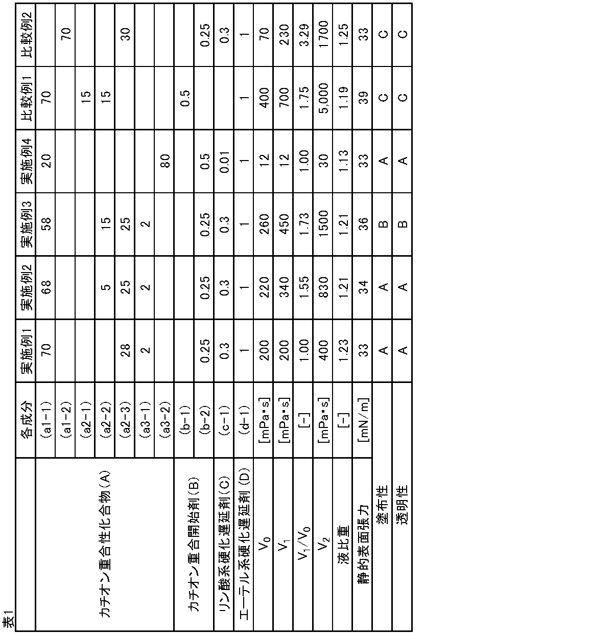
得られた封止剤について、以下に示す評価方法で封止剤の各種粘度、液比重、静的表面張力を測定した。また、得られた封止剤について、以下に示す評価方法で塗布性を評価した。また、得られた封止剤を、以下に示す光硬化条件で硬化して硬化体を形成し、以下に示す評価方法で透明性を評価した。評価結果は表1に示す。
(a1-1)3’,4’-エポキシシクロヘキシルメチル-3,4-エポキシシクロヘキサンカルボキシレート(ダイセル化学社製「セロキサイド2021P」)
(a1-2)(3,3’,4,4’-ジエポキシ)ビシクロヘキシル(ダイセル化学社製「セロキサイド8010」)
(a2-1)ビスフェノールA型エポキシ樹脂(分子量360~390、三菱化学社製「jER828」)
(a2-2)ビスフェノールF型エポキシ樹脂(分子量320~340、三菱化学社製「jER806」)
(a2-3)ジブロモフェニルグリシジルエーテル(日本化薬社製「BR-250H」、分子量308)
(a3-1)1,6-ヘキサンジオールのジグリシジルエーテル(ADEKA社製「ED-503G」)
(a3-2)ネオペンチルグリコールのジグリシジルエーテル(ナガセケムテックス社製「デナコールEX-211」)
(b-1)トリアリールスルホニウム塩ヘキサフルオロアンチモネート(ADEKA社製「アデカオプトマーSP-170」、アニオン種はヘキサフルオロアンチモネート)
(b-2)トリアリールスルホニウム-テトラキスペンタフルオロフェニルガレート(サンアプロ社製「CPI-310FG」)
(c-1)トリス(2-エチルヘキシル)ホスフェート(大八化学工業社製「TOP」)
(d-1)18-クラウン-6-エーテル(東京化成工業社製「クラウンエーテル O-18」)
実施例および比較例の封止剤について、下記測定条件1により粘度測定をおこなった。
粘度測定開始時から20秒後の粘度をV0とし、測定開始時から30秒後に無アルカリガラス板から15cm離れた地点から前記無アルカリガラス板に向かって垂直に、波長365nm、30mW/cm2の紫外線を20秒間照射(合計600mJ/cm2)し、前記紫外線照射完了時から60秒後の粘度をV1とし、前記紫外線照射完了時から10分後の粘度をV2とした。ここで、紫外線照射は、粘度を連続的に測定しながら、レオメータに附属の紫外線照射装置(HOYA社製、超高圧水銀ランプ照射装置「EXECURE3000」)を用いて行った。また、「測定開始時」とは、サンプルを装置にセットし、回転開始時を意味する。
<測定条件1>
装置:レオメータ(アントンパール社製、製品名「MCR301」)
温度:25℃
ジオメトリー(上側):直径8mmφ、アルミニウム製パラレルプレート
プレート(下側):直径38mmφ、無アルカリガラス板
せん断速度:1min-1
ギャップ:0.05mm
サンプル量:20mg
雰囲気:窒素フロー(1000mL/分)
実施例および比較例の封止剤の液比重は5mLゲーリュサック型比重瓶を用い、JIS-K-0061の8.2.2に準拠して測定した。
実施例および比較例の封止剤の静的表面張力は23℃の雰囲気下、接触角計(協和界面科学社製DM500)を用いて、ペンダントドロップ法により測定した。
25mm角のカラーフィルター上に10μLの封止剤を滴下し、高圧水銀ランプでUVを600mJ/cm2照射し、10分静置後に無アルカリガラス板を貼り合わせ、1kgの分銅を乗せて、1分間静置した。静置後に封止剤が広がった面積を画像計算ソフトにより算出した。
塗布性は以下の基準により評価した。
A(非常に良好):封止剤が広がった面積が625mm2
B(良好):封止剤が広がった面積が300mm2以上、625mm2未満
C(不良):封止剤が広がった面積が300mm2未満
50mm角のカラーフィルター上に封止剤を全量0.024gになるよう等間隔で塗布し、高圧水銀ランプでUVを600mJ/cm2照射し、10分静置後に無アルカリガラス板を貼り合わせ、0.05kNで真空プレスした。プレス後、液滴間の気泡の状態を確認した。
透明性は以下の基準により評価した。
A(非常に良好):気泡なし
B(良好):気泡あり
C(不良):液滴同士が接することなく塗布した位置に円形状で存在
Claims (29)
- カチオン重合性化合物(A)と、カチオン重合開始剤(B)と、硬化遅延剤(X)とを含む封止剤であって、
下記測定条件1による粘度測定における、測定開始時から20秒後の粘度をV0とし、測定開始時から30秒後に無アルカリガラス板から15cm離れた地点から前記無アルカリガラス板に向かって垂直に、波長365nm、30mW/cm2の紫外線を20秒間照射(合計600mJ/cm2)し、前記紫外線照射完了時から60秒後の粘度をV1としたとき、V1/V0により示される粘度変化率が1.00以上1.75未満である封止剤。
<測定条件1>
装置:レオメータ
温度:25℃
ジオメトリー(上側):直径8mmφ、アルミニウム製パラレルプレート
プレート(下側):直径38mmφ、無アルカリガラス板
せん断速度:1min-1
ギャップ:0.05mm
サンプル量:20mg
雰囲気:窒素フロー - 前記粘度V0が1mPa・s以上1000mPa・s以下である、請求項1に記載の封止剤。
- 前記粘度V1が1mPa・s以上2000mPa・s以下である、請求項1または2に記載の封止剤。
- 前記カチオン重合性化合物(A)がエポキシ基を含む、請求項1または2に記載の封止剤。
- 前記カチオン重合性化合物(A)が、エポキシ基を有する脂環式化合物(A-1)、エポキシ基を有する芳香族化合物(A-2)およびグリシジルエーテル化合物(A-3)からなる群から選択される一種または二種以上を含む、請求項4に記載の封止剤。
- 前記カチオン重合性化合物(A)が臭素原子を含む、請求項1または2に記載の封止剤。
- 前記測定条件1による粘度測定における、前記紫外線照射完了時から10分後の粘度V2が5000mPa・s以下である、請求項1または2に記載の封止剤。
- 25℃雰囲気下における液比重が1.10以上である、請求項1または2に記載の封止剤。
- ペンダントドロップ法による静的表面張力が50mN/m以下である、請求項1または2に記載の封止剤。
- 前記カチオン重合開始剤(B)が、光カチオン重合開始剤(B1)および熱カチオン重合開始剤(B2)からなる群から選択される一種または二種以上を含む、請求項1または2に記載の封止剤。
- 前記カチオン重合開始剤(B)がオニウム塩化合物を含む、請求項10に記載の封止剤。
- 前記カチオン重合開始剤(B)の含有量が、前記カチオン重合性化合物(A)100質量部に対して0.01質量部以上5.0質量部以下である、請求項1または2に記載の封止剤。
- 前記硬化遅延剤(X)が、リン酸系硬化遅延剤、エーテル系硬化遅延剤、チオエーテル系硬化遅延剤、金属錯体系硬化遅延剤、およびニトロキシラジカル系硬化遅延剤からなる群から選択される一種または二種以上を含む、請求項1または2に記載の封止剤。
- 前記硬化遅延剤(X)の含有量が、前記カチオン重合性化合物(A)100質量部に対して0.10質量部以上10.0質量部以下である、請求項1または2に記載の封止剤。
- 発光ダイオード素子用である、請求項1または2に記載の封止剤。
- カラーフィルターと有機エレクトロルミネッセンス表示素子の接合用またはカラーフィルターとマイクロLEDの接合用である、請求項1または2に記載の封止剤。
- 太陽電池セルを封止するために用いることが可能である、請求項1または2に記載の封止剤。
- 前記太陽電池セルがペロブスカイト型太陽電池セルを含む、請求項17に記載の封止剤。
- 請求項1または2に記載の封止剤を硬化してなる、硬化体。
- 発光ダイオード素子と、基板と、前記発光ダイオード素子と前記基板との間に位置する請求項19に記載の硬化体により形成された硬化封止層と、を備える表示装置。
- 前記発光ダイオード素子が有機エレクトロルミネッセンス表示素子またはマイクロLEDを含む、請求項20に記載の表示装置。
- 前記基板がカラーフィルターを含む、請求項20に記載の表示装置。
- 第一の部材に、請求項1または2に記載の封止剤を塗布する塗布工程と、
塗布した前記封止剤に光を照射する照射工程と、
光照射された前記封止剤を介して、前記第一の部材と第二の部材とを貼り合わせる貼合工程と、
を含む、表示装置の製造方法。 - 前記第一の部材および前記第二の部材の一方が基板であり、他方が発光ダイオード素子である、請求項23に記載の表示装置の製造方法。
- 前記発光ダイオード素子が有機エレクトロルミネッセンス表示素子またはマイクロLEDを含む、請求項24に記載の表示装置の製造方法。
- 前記基板がカラーフィルターを含む、請求項24に記載の表示装置の製造方法。
- 太陽電池セルと、基材と、前記太陽電池セルと前記基材との間に請求項19に記載の硬化体を含む硬化封止層と、を備える、太陽電池。
- 前記太陽電池セルがペロブスカイト型太陽電池セルを含む、請求項27に記載の太陽電池。
- カチオン重合性化合物(A)と、カチオン重合開始剤(B)と、硬化遅延剤(X)とを含む組成物であって、
下記測定条件1による粘度測定における、測定開始時から20秒後の粘度をV0とし、測定開始時から30秒後に無アルカリガラス板から15cm離れた地点から前記無アルカリガラス板に向かって垂直に、波長365nm、30mW/cm2の紫外線を20秒間照射(合計600mJ/cm2)し、前記紫外線照射完了時から60秒後の粘度をV1としたとき、V1/V0により示される粘度変化率が1.00以上1.75未満である組成物。
<測定条件1>
装置:レオメータ
温度:25℃
ジオメトリー(上側):直径8mmφ、アルミニウム製パラレルプレート
プレート(下側):直径38mmφ、無アルカリガラス板
せん断速度:1min-1
ギャップ:0.05mm
サンプル量:20mg
雰囲気:窒素フロー
Priority Applications (2)
| Application Number | Priority Date | Filing Date | Title |
|---|---|---|---|
| CN202380073265.1A CN120167005A (zh) | 2022-11-04 | 2023-10-30 | 密封剂、固化体、显示装置、显示装置的制造方法、太阳能电池及组合物 |
| JP2024554493A JPWO2024095948A1 (ja) | 2022-11-04 | 2023-10-30 |
Applications Claiming Priority (2)
| Application Number | Priority Date | Filing Date | Title |
|---|---|---|---|
| JP2022177417 | 2022-11-04 | ||
| JP2022-177417 | 2022-11-04 |
Publications (1)
| Publication Number | Publication Date |
|---|---|
| WO2024095948A1 true WO2024095948A1 (ja) | 2024-05-10 |
Family
ID=90930529
Family Applications (1)
| Application Number | Title | Priority Date | Filing Date |
|---|---|---|---|
| PCT/JP2023/039038 Ceased WO2024095948A1 (ja) | 2022-11-04 | 2023-10-30 | 封止剤、硬化体、表示装置、表示装置の製造方法、太陽電池および組成物 |
Country Status (4)
| Country | Link |
|---|---|
| JP (1) | JPWO2024095948A1 (ja) |
| CN (1) | CN120167005A (ja) |
| TW (1) | TW202424034A (ja) |
| WO (1) | WO2024095948A1 (ja) |
Cited By (2)
| Publication number | Priority date | Publication date | Assignee | Title |
|---|---|---|---|---|
| CN119039325A (zh) * | 2024-08-19 | 2024-11-29 | 上海电机学院 | 一种含有氮氧自由基的铜基卤化物及其应用 |
| WO2026074870A1 (ja) * | 2024-10-01 | 2026-04-09 | 東亞合成株式会社 | 活性エネルギー線硬化型組成物、硬化物、及び、光学部材 |
Citations (4)
| Publication number | Priority date | Publication date | Assignee | Title |
|---|---|---|---|---|
| WO2012090932A1 (ja) * | 2010-12-27 | 2012-07-05 | 株式会社スリーボンド | 光電変換素子用封止剤組成物 |
| JP2016160415A (ja) * | 2015-03-05 | 2016-09-05 | 横浜ゴム株式会社 | 導電性組成物、太陽電池セルおよび太陽電池モジュール |
| WO2020067046A1 (ja) * | 2018-09-26 | 2020-04-02 | デンカ株式会社 | 有機エレクトロルミネッセンス表示素子用封止剤 |
| WO2020171186A1 (ja) * | 2019-02-21 | 2020-08-27 | デンカ株式会社 | 組成物 |
-
2023
- 2023-10-30 JP JP2024554493A patent/JPWO2024095948A1/ja active Pending
- 2023-10-30 WO PCT/JP2023/039038 patent/WO2024095948A1/ja not_active Ceased
- 2023-10-30 CN CN202380073265.1A patent/CN120167005A/zh active Pending
- 2023-11-02 TW TW112142153A patent/TW202424034A/zh unknown
Patent Citations (4)
| Publication number | Priority date | Publication date | Assignee | Title |
|---|---|---|---|---|
| WO2012090932A1 (ja) * | 2010-12-27 | 2012-07-05 | 株式会社スリーボンド | 光電変換素子用封止剤組成物 |
| JP2016160415A (ja) * | 2015-03-05 | 2016-09-05 | 横浜ゴム株式会社 | 導電性組成物、太陽電池セルおよび太陽電池モジュール |
| WO2020067046A1 (ja) * | 2018-09-26 | 2020-04-02 | デンカ株式会社 | 有機エレクトロルミネッセンス表示素子用封止剤 |
| WO2020171186A1 (ja) * | 2019-02-21 | 2020-08-27 | デンカ株式会社 | 組成物 |
Cited By (3)
| Publication number | Priority date | Publication date | Assignee | Title |
|---|---|---|---|---|
| CN119039325A (zh) * | 2024-08-19 | 2024-11-29 | 上海电机学院 | 一种含有氮氧自由基的铜基卤化物及其应用 |
| CN119039325B (zh) * | 2024-08-19 | 2025-10-10 | 上海电机学院 | 一种含有氮氧自由基的铜基卤化物及其应用 |
| WO2026074870A1 (ja) * | 2024-10-01 | 2026-04-09 | 東亞合成株式会社 | 活性エネルギー線硬化型組成物、硬化物、及び、光学部材 |
Also Published As
| Publication number | Publication date |
|---|---|
| TW202424034A (zh) | 2024-06-16 |
| JPWO2024095948A1 (ja) | 2024-05-10 |
| CN120167005A (zh) | 2025-06-17 |
Similar Documents
| Publication | Publication Date | Title |
|---|---|---|
| JP6200591B2 (ja) | インクジェット塗布用電子デバイス用封止剤及び電子デバイスの製造方法 | |
| CN108699216B (zh) | 固化性树脂组合物和有机电致发光显示元件用密封剂 | |
| JP7270635B2 (ja) | 有機エレクトロルミネッセンス表示素子用封止剤 | |
| JP2017228414A (ja) | 有機エレクトロルミネッセンス表示素子用封止剤 | |
| WO2019117298A1 (ja) | 電子デバイス用封止剤及び有機el表示素子用封止剤 | |
| CN105026456A (zh) | 光后固化性树脂组合物 | |
| TW202424034A (zh) | 密封劑、硬化體、顯示裝置、顯示裝置之製造方法、太陽能電池及組合物 | |
| CN111480392B (zh) | 电子设备用密封剂及有机el显示元件用密封剂 | |
| JP2019147963A (ja) | 有機エレクトロルミネッセンス表示素子用封止剤 | |
| CN110583098B (zh) | 有机el显示元件用密封剂 | |
| WO2019003991A1 (ja) | 有機el素子の封止用のカチオン重合硬化型インクジェット用樹脂組成物 | |
| JP2023029649A (ja) | 有機el表示素子用封止剤 | |
| CN113166371B (zh) | 有机el显示元件用密封剂 | |
| WO2025173628A1 (ja) | 組成物、硬化体、表示装置および太陽電池 | |
| WO2024195593A1 (ja) | 組成物、硬化体、表示装置及び表示装置の製造方法 | |
| WO2024195590A1 (ja) | 組成物、硬化体、表示装置及び表示装置の製造方法 | |
| JP2026083450A (ja) | 組成物、硬化体、表示装置及び表示装置の製造方法 | |
| TW202313710A (zh) | 硬化性樹脂組成物、顯示元件用密封劑、有機el顯示元件用密封劑、光學接著劑、及光學構件 | |
| TW202323462A (zh) | 硬化性樹脂組成物、塗覆層、及膜 |
Legal Events
| Date | Code | Title | Description |
|---|---|---|---|
| 121 | Ep: the epo has been informed by wipo that ep was designated in this application |
Ref document number: 23885703 Country of ref document: EP Kind code of ref document: A1 |
|
| WWE | Wipo information: entry into national phase |
Ref document number: 2024554493 Country of ref document: JP |
|
| WWE | Wipo information: entry into national phase |
Ref document number: 202380073265.1 Country of ref document: CN |
|
| NENP | Non-entry into the national phase |
Ref country code: DE |
|
| WWP | Wipo information: published in national office |
Ref document number: 202380073265.1 Country of ref document: CN |
|
| 122 | Ep: pct application non-entry in european phase |
Ref document number: 23885703 Country of ref document: EP Kind code of ref document: A1 |