WO2024095399A1 - 切削工具 - Google Patents
切削工具 Download PDFInfo
- Publication number
- WO2024095399A1 WO2024095399A1 PCT/JP2022/041008 JP2022041008W WO2024095399A1 WO 2024095399 A1 WO2024095399 A1 WO 2024095399A1 JP 2022041008 W JP2022041008 W JP 2022041008W WO 2024095399 A1 WO2024095399 A1 WO 2024095399A1
- Authority
- WO
- WIPO (PCT)
- Prior art keywords
- flow path
- cutting tool
- axis
- peripheral surface
- end surface
- Prior art date
- Legal status (The legal status is an assumption and is not a legal conclusion. Google has not performed a legal analysis and makes no representation as to the accuracy of the status listed.)
- Ceased
Links
Images




Classifications
-
- B—PERFORMING OPERATIONS; TRANSPORTING
- B23—MACHINE TOOLS; METAL-WORKING NOT OTHERWISE PROVIDED FOR
- B23C—MILLING
- B23C5/00—Milling-cutters
- B23C5/28—Features relating to lubricating or cooling
-
- B—PERFORMING OPERATIONS; TRANSPORTING
- B23—MACHINE TOOLS; METAL-WORKING NOT OTHERWISE PROVIDED FOR
- B23C—MILLING
- B23C5/00—Milling-cutters
- B23C5/16—Milling-cutters characterised by physical features other than shape
- B23C5/20—Milling-cutters characterised by physical features other than shape with removable cutter bits or teeth or cutting inserts
- B23C5/22—Securing arrangements for bits or teeth or cutting inserts
- B23C5/2204—Securing arrangements for bits or teeth or cutting inserts with cutting inserts clamped against the walls of the recess in the cutter body by a clamping member acting upon the wall of a hole in the insert
-
- B—PERFORMING OPERATIONS; TRANSPORTING
- B23—MACHINE TOOLS; METAL-WORKING NOT OTHERWISE PROVIDED FOR
- B23C—MILLING
- B23C5/00—Milling-cutters
- B23C5/28—Features relating to lubricating or cooling
- B23C5/282—Coolant channel characterised by its cross-sectional shape
-
- B—PERFORMING OPERATIONS; TRANSPORTING
- B23—MACHINE TOOLS; METAL-WORKING NOT OTHERWISE PROVIDED FOR
- B23C—MILLING
- B23C2210/00—Details of milling cutters
- B23C2210/16—Fixation of inserts or cutting bits in the tool
- B23C2210/168—Seats for cutting inserts, supports for replacable cutting bits
Definitions
- This disclosure relates to cutting tools.
- Patent Document 1 JP 2010-234457 A discloses a cutting tool in which multiple cutting inserts are attached to the tool body.
- the tool body is formed with ejection holes that eject coolant toward the cutting inserts.
- the cutting tool according to the present disclosure is configured to be rotatable around an axis.
- the cutting tool includes a body and a cutting insert.
- the body includes a front end surface, a rear end surface, and an outermost surface.
- the rear end surface is opposite the front end surface.
- the outermost surface is continuous with each of the front end surface and the rear end surface.
- a pocket is formed in the outermost surface.
- the cutting insert is disposed in the pocket.
- the body includes a first member, a second member, a support member, and a fixing member.
- the first member surrounds the axis.
- the first member has a first outer peripheral surface.
- the second member has an inner peripheral surface.
- the inner peripheral surface surrounds the first outer peripheral surface.
- the second member forms each of the front end surface, the rear end surface, and the outermost surface.
- the support member connects the first outer peripheral surface and the inner peripheral surface.
- the support member is spaced apart from each of the front end surface and the rear end surface.
- the fixing member closes a gap between the first outer peripheral surface and the inner peripheral surface.
- a through hole is formed in the first member. The through hole extends along the axis.
- a space is formed between the first member and the second member. The space surrounds the through hole.
- a flow path is formed in the second member. The flow path is connected to the space. The flow path opens at the outermost peripheral surface.
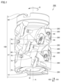
- FIG. 1 is a schematic perspective view showing the configuration of a cutting tool according to a first embodiment.
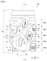
- FIG. 2 is a schematic front view showing the configuration of the cutting tool according to the first embodiment.
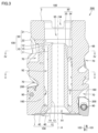
- FIG. 3 is a schematic vertical cross-sectional view taken along line III-III in FIG.
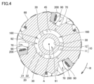
- FIG. 4 is a schematic cross-sectional view taken along line IV-IV in FIG.
- FIG. 5 is a schematic cross-sectional view taken along line VV in FIG.
- FIG. 6 is an enlarged perspective schematic view showing the configuration of the cutting insert and the pocket.
- FIG. 7 is an enlarged perspective schematic diagram showing the configuration of the pocket.
- FIG. 8 is a schematic vertical cross-sectional view showing the cross-sectional shape of the first flow path portion.
- FIG. 9 is an enlarged schematic cross-sectional view showing region IX in FIG.
- FIG. 10 is a schematic partial cross-sectional view showing the configuration of a cutting tool according to the second embodiment.
- FIG. 11 is a schematic bottom view showing the configuration of the holder.
- FIG. 12 is a schematic cross-sectional view taken along line XII-XII in FIG.
- FIG. 13 is an enlarged perspective schematic view showing the flow of cutting fluid around the cutting insert.
- An object of the present disclosure is to provide a cutting tool capable of increasing the flow rate of cutting fluid discharged from the outermost peripheral surface of the body.
- the cutting tool 500 is configured to be rotatable around the axis A.
- the cutting tool 500 includes a body 100 and a cutting insert 200.
- the body 100 includes a front end surface 1, a rear end surface 2, and an outermost surface 21.
- the rear end surface 2 is opposite the front end surface 1.
- the outermost surface 21 is continuous with each of the front end surface 1 and the rear end surface 2.
- a pocket 70 is formed in the outermost surface 21.
- the cutting insert 200 is disposed in the pocket 70.
- the body 100 includes a first member 10, a second member 20, a support member 30, and a fixing member 40.
- the first member 10 surrounds the axis A.
- the first member 10 has a first outer peripheral surface 11.
- the second member 20 has an inner peripheral surface 22.
- the inner peripheral surface 22 surrounds the first outer peripheral surface 11.
- the second member 20 forms the front end surface 1, the rear end surface 2, and the outermost surface 21.
- the support member 30 connects the first outer peripheral surface 11 and the inner peripheral surface 22.
- the support member 30 is spaced apart from the front end surface 1 and the rear end surface 2.
- the fixing member 40 closes the gap between the first outer peripheral surface 11 and the inner peripheral surface 22.
- the first member 10 has a through hole 91 formed therein.
- the through hole 91 extends along the axis A.
- a space 92 is formed between the first member 10 and the second member 20.
- the space 92 surrounds the through hole 91.
- the second member 20 has a flow path 50 formed therein.
- the flow path 50 is connected to the space 92.
- the flow path 50 opens at the outermost surface 21.
- the cutting fluid supplied into the body 100 flows into the space 92. This reduces the flow rate of cutting fluid flowing out into the through hole 91. This prevents the cutting fluid from flowing out to the outside of the body 100 through the through hole 91. As a result, the flow rate of cutting fluid discharged from the outermost surface 21 can be increased compared to when the space 92 is not formed.
- the flow path 50 may have a flow path portion 53 that is curved when viewed along the axis A. This improves the design freedom of the flow path portion 53 while reducing the pressure loss of the cutting fluid flowing through the flow path portion 53.
- the shape of the flow passage 50 is elliptical in a cross section perpendicular to the direction in which the flow passage 50 extends.
- the first width W1 may be larger than the second width W2.
- the cutting insert 200 may include a bottom surface 83 and a rake surface 81.
- the bottom surface 83 may be in contact with the outermost peripheral surface 21.
- the rake surface 81 may be opposite to the bottom surface 83.
- the outermost peripheral surface 21 may have a seat surface 41 and a first surface 61.
- the seat surface 41 may be in contact with the bottom surface 83.
- the first surface 61 may be forward of the seat surface 41 in the rotation direction R.
- the seat surface 41 and the first surface 61 may form a pocket 70.
- the flow path 50 may have a first flow path portion 51.
- the first flow path portion 51 may be open at the first surface 61.
- the first flow path portion 51 may be open toward the rake surface 81. This allows the cutting edge 84 connected to the rake surface 81 to be effectively cooled.
- the flow path 50 may have a second flow path section 52.
- the second flow path section 52 may open on the first surface 61.
- the second flow path section 52 may be spaced apart from the first flow path section 51.
- the second flow path section 52 may open toward the rake face 81.
- a first opening 151 and a second opening 152 may be formed on the first surface 61.
- the first opening 151 may be connected to the first flow path section 51.
- the second opening 152 may be connected to the second flow path section 52.
- the area of the first opening 151 may be different from the area of the second opening 152.
- the flow path 50 may have a second flow path section 52.
- the second flow path section 52 may open at the first surface 61.
- the second flow path section 52 may be spaced apart from the first flow path section 51.
- the second flow path section 52 may open toward the rake face 81.
- the first area may be different from the second area.
- the cutting insert 200 may include a clearance surface 82.
- the clearance surface 82 may be continuous with the rake surface 81.
- the outermost peripheral surface 21 may have a second surface 62.
- the second surface 62 may be located rearward of the seat surface 41 in the rotation direction R.
- the second surface 62 may be located in a direction from the axis A toward the outermost peripheral surface 21 with respect to the seat surface 41.
- the flow path 50 may have a third flow path portion 53.
- the third flow path portion 53 may be open at the second surface 62.
- the third flow path portion 53 may be open toward the clearance surface 82. This allows the cutting edge 84 continuous with the clearance surface 82 to be effectively cooled.
- the first member 10 may include a first inner peripheral surface 12.
- the first inner peripheral surface 12 may form a through hole 91.
- the first inner peripheral surface 12 may have a first inner peripheral surface portion 13 and a second inner peripheral surface portion 14.
- the first inner peripheral surface portion 13 extends along the axis A.
- the second inner peripheral surface portion 14 is located between the first inner peripheral surface portion 13 and the front end face 1.
- the second inner peripheral surface portion 14 is inclined with respect to the first inner peripheral surface portion 13. The diameter of the second inner peripheral surface portion 14 may become smaller as it moves away from the front end face 1.
- the cutting tool 500 may further include a holder 300.
- the holder 300 may be configured to supply cutting fluid to the space 92.
- At least one discharge port 98 may be formed in the holder 300.
- the first member 10, the second member 20, and the support member 30 may form at least one inlet 99.
- the at least one inlet 99 may be connected to the space 92.
- the at least one discharge port 98 may overlap with the at least one inlet 99.
- the number of the at least one discharge port 98 may be the same as the number of the at least one inlet 99.
- FIG. 1 is a schematic perspective view showing the configuration of a cutting tool 500 according to the first embodiment.
- FIG. 2 is a schematic front view showing the configuration of a cutting tool 500 according to the first embodiment.
- the cutting tool 500 mainly has a body 100, a plurality of cutting inserts 200, and a plurality of first fastening screws 90.
- the cutting tool 500 is configured to be rotatable around an axis A. In other words, the cutting tool 500 is a rotary cutting tool.
- the cutting tool 500 is, for example, an end mill.
- the cutting tool 500 is, for example, a repeater cutter.
- the body 100 has a first front end face 1, a first rear end face 2, a second outer peripheral surface 21, and a first inner peripheral surface 12.
- the first rear end face 2 is opposite the first front end face 1.
- the first rear end face 2 is disposed so as to face a tool spindle (not shown) that rotates the cutting tool 500.
- the direction from the first front end face 1 to the first rear end face 2 is defined as a first direction 101.
- the direction from the first rear end face 2 to the first front end face 1 is defined as a third direction 103.
- the second outer peripheral surface 21 is connected to each of the first front end surface 1 and the first rear end surface 2.
- the second outer peripheral surface 21 is the outermost surface of the body 100.
- the second outer peripheral surface 21 surrounds the axis A.
- the second outer peripheral surface 21 has an outermost surface portion 68.
- a plurality of pockets 70 are formed in the second outer peripheral surface 21. Each of the plurality of pockets 70 is recessed inward with respect to the outermost surface portion 68. The inward direction is the direction from the second outer peripheral surface 21 toward the axis A.
- the first inner peripheral surface 12 is continuous with the first front end face 1.
- the first inner peripheral surface 12 surrounds the axis A.
- the first inner peripheral surface 12 is surrounded by the second outer peripheral surface 21.
- a first through hole 91 is formed in the body 100.
- the first inner peripheral surface 12 forms the first through hole 91.
- a groove portion 94 is formed in the first rear end face 2. The groove portion 94 extends, for example, along a direction perpendicular to the axis A.
- the cutting insert 200 is disposed in the pocket 70. Specifically, one cutting insert 200 is disposed in one pocket 70. On the second outer peripheral surface 21, the cutting insert 200 is disposed along a curve that extends spirally around the axis A. The cutting insert 200 is attached to the body 100 using the first fastening screw 90.
- the number of cutting inserts 200 attached to the body 100 is, for example, 15. Three cutting inserts 200 are arranged in a row in the rotation direction R. In other words, three cutting inserts 200 form one stage. The number of stages of the cutting inserts 200 is five. From another perspective, the cutting inserts 200 are classified into three groups. One group includes five cutting inserts 200. The five cutting inserts 200 included in one group are arranged along a spiral curve. In other words, the cutting inserts 200 are arranged along each of the three spiral curves. Each of the three spiral curves is spaced apart from each other.
- the number of pockets 70 formed on the second outer peripheral surface 21 is, for example, 15.
- Three pockets 70 are arranged in a row in the rotational direction R. In other words, three pockets 70 form one stage.
- the number of stages of the pockets 70 is five.
- the pockets 70 are classified into three groups. One group includes five pockets 70.
- the five pockets 70 included in one group are arranged along a spiral curve. In other words, the pockets 70 are arranged along each of the three spiral curves.
- the five pockets 70 included in one group may be connected to each other.
- FIG. 3 is a schematic vertical cross-sectional view taken along line III-III in FIG. 2.
- the cross-section shown in FIG. 3 includes axis A and intersects with the support member 30.
- the body 100 has a first member 10, a second member 20, a support member 30, and a fixing member 40.
- the first member 10 extends along the axis A.
- the first member 10 has a first outer peripheral surface 11, an inclined surface 15, and a first inner peripheral surface 12.
- the first outer peripheral surface 11 extends along the axis A.
- the inclined surface 15 is continuous with each of the first outer peripheral surface 11 and the first inner peripheral surface 12.
- the first inner circumferential surface 12 has a first inner circumferential surface portion 13 and a second inner circumferential surface portion 14.
- the first inner circumferential surface portion 13 is connected to the inclined surface 15.
- the first inner circumferential surface portion 13 extends along the axis A.
- the second inner circumferential surface portion 14 is connected to the first inner circumferential surface portion 13.
- the second inner circumferential surface portion 14 In the first direction 101, the second inner circumferential surface portion 14 is located between the first inner circumferential surface portion 13 and the first front end face 1.
- the second inner circumferential surface portion 14 may be connected to the first front end face 1.
- the second inner circumferential surface portion 14 is inclined outward relative to the first inner circumferential surface portion 13. From another perspective, the diameter of the second inner circumferential surface portion 14 becomes smaller as it moves away from the first front end face 1.
- the outward direction is the direction from the axis A toward the second outer circumferential surface 21.
- the second member 20 forms each of the first front end surface 1, the first rear end surface 2, and the second outer peripheral surface 21.
- the second member 20 has a second inner peripheral surface 22.
- the second inner peripheral surface 22 is spaced apart from each of the first outer peripheral surface 11 and the first front end surface 1.
- the second inner peripheral surface 22 faces the first outer peripheral surface 11.
- the second inner peripheral surface 22 is continuous with the first rear end surface 2.
- the second inner peripheral surface 22 extends along the axis A.
- the second inner peripheral surface 22 may be substantially parallel to the first outer peripheral surface 11.
- the support member 30 is between the first outer peripheral surface 11 and the second inner peripheral surface 22.
- the support member 30 connects the first member 10 and the second member 20. Specifically, the support member 30 connects the first outer peripheral surface 11 and the second inner peripheral surface 22.
- the support member 30 is spaced apart from each of the first front end surface 1 and the first rear end surface 2. In the first direction 101, the support member 30 is located between the first front end surface 1 and the first rear end surface 2.
- the support member 30 has a fourth surface 34 and a fifth surface 35.
- the fourth surface 34 is continuous with each of the inclined surface 15 and the second inner peripheral surface 22. In the first direction 101, the fourth surface 34 may be located between the inclined surface 15 and the first front end surface 1.
- the fourth surface 34 is, for example, planar.
- the fifth surface 35 is opposite the fourth surface 34. Specifically, the fifth surface 35 is in the third direction 103 relative to the fourth surface 34.
- the fifth surface 35 is continuous with each of the first outer peripheral surface 11 and the second inner peripheral surface 22.
- the fifth surface 35 is recessed in the first direction 101. In the first direction 101, the fifth surface 35 is between the fourth surface 34 and the first front end surface 1.
- the fixed member 40 connects the first member 10 and the second member 20, and closes the gap between the first outer peripheral surface 11 and the second inner peripheral surface 22.
- the fixed member 40 is spaced apart from the support member 30.
- the fixed member 40 is located in a third direction 103 relative to the support member 30.
- the fixed member 40 may form a part of the first front end surface 1.
- the fixed member 40 surrounds the axis A.
- the fixed member 40 has a third surface 45.
- the third surface 45 is continuous with each of the first outer peripheral surface 11 and the second inner peripheral surface 22.
- the third surface 45 faces the fifth surface 35 of the support member 30.
- the first member 10 has a first through hole 91 formed therein.
- the first through hole 91 may penetrate the first front end surface 1 and the inclined surface 15.
- the first through hole 91 extends along the axis A.
- An insertion hole 95 is formed in the body 100.
- the insertion hole 95 extends along the axis A.
- the insertion hole 95 is formed by the second inner peripheral surface 22.
- the insertion hole 95 opens at the first rear end surface 2.
- the insertion hole 95 is connected to the first through hole 91.
- the insertion hole 95 is formed in the first direction 101 relative to the first through hole 91.
- a space 92 is formed between the first member 10 and the second member 20. Specifically, the space 92 is formed by the first outer peripheral surface 11, the second inner peripheral surface 22, and the third surface 45. The space 92 is connected to the insertion hole 95. The space 92 is spaced apart from the first through hole 91. From another perspective, the space 92 is separated from the first through hole 91 by the first member 10. The space 92 is separated from the outside of the body 100 by the second member 20 and the fixing member 40. The space 92 extends along the axis A.
- connection ports 160 are formed on the second inner circumferential surface 22.
- the connection ports 160 connect the space 92 and the flow path 50. From another perspective, the flow path 50 opens on the second inner circumferential surface 22. Details of the flow path 50 will be described later.
- the plurality of connection ports 160 are spaced apart from the insertion hole 95. In the first direction 101, the connection ports 160 are located between the third surface 45 and the inclined surface 15.
- FIG. 4 is a schematic cross-sectional view taken along line IV-IV in FIG. 3.
- the cross section shown in FIG. 4 is perpendicular to axis A and intersects with support member 30.
- the first member 10 surrounds the axis A.
- the first inner circumferential surface 12 surrounds the axis A.
- the first member 10 has an annular shape.
- the second member 20 surrounds the first member 10.
- the second inner circumferential surface 22 surrounds the first member 10.
- the second member 20 has an annular shape.
- the third surface 45 surrounds the axis A. When viewed along the axis A, the third surface 45 has an annular shape.
- a plurality of connection ports 160 may be formed in the third surface 45.
- the body 100 has a plurality of support members 30.
- the number of support members 30 is, for example, three.
- Each of the three support members 30 is spaced apart from one another.
- the three support members 30 are positioned, for example, so as to be three-fold symmetrical with respect to the axis A.
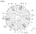
- FIG. 5 is a schematic cross-sectional view taken along line V-V in FIG. 3.
- the cross section shown in FIG. 5 is perpendicular to axis A and passes between support member 30 and fixed member 40 in first direction 101.
- space 92 surrounds first through hole 91. From another perspective, space 92 surrounds axis A. When viewed along axis A, space 92 is annular.
- FIG. 6 is an enlarged perspective schematic diagram showing the configuration of the cutting insert 200 and the pocket 70.
- the cutting insert 200 has a bottom surface 83, a scooping surface 81, a clearance surface 82, and a flat surface 80.
- the bottom surface 83 is in contact with the second outer peripheral surface 21 of the body 100.
- the bottom surface 83 is, for example, flat.
- the scooping surface 81 is opposite the bottom surface 83.
- the clearance surface 82 is continuous with each of the scooping surface 81 and the bottom surface 83.
- the ridge between the scooping surface 81 and the clearance surface 82 forms a cutting edge 84.
- the cutting edge 84 may be formed so as to incline backward in the direction of rotation R as it moves away from the first front end surface 1 (see FIGS. 1 and 2) in the first direction 101.
- the flat surface 80 is opposite the bottom surface 83.
- the flat surface 80 is continuous with the scooping surface 81.
- a second through hole 79 is formed in the plane
- FIG. 7 is an enlarged perspective schematic diagram showing the configuration of the pocket 70.
- the enlarged perspective schematic diagram shown in FIG. 7 corresponds to the enlarged perspective schematic diagram shown in FIG. 6.
- some of the multiple cutting inserts 200 are not shown.
- the second outer peripheral surface 21 has a first seating surface 41, a second seating surface 42, a third seating surface 43, a first surface 61, and a second surface 62.
- the first seating surface 41, the second seating surface 42, the third seating surface 43, the first surface 61, and the second surface 62 form a pocket 70.
- Each of the first seating surface 41, the second seating surface 42, and the third seating surface 43 is a surface on which the cutting insert 200 is disposed.
- the first seating surface 41 contacts the bottom surface 83 of the cutting insert 200.
- the first seating surface 41 is, for example, planar.
- the second seating surface 42 is located in the third direction 103 relative to the first seating surface 41.
- the second seating surface 42 is, for example, planar.
- the third seating surface 43 is located in the first direction 101 relative to the second seating surface 42.
- the third seating surface 43 is, for example, planar.
- the third seating surface 43 is located on the inside relative to each of the first seating surface 41 and the second seating surface 42.
- the radial direction is a direction perpendicular to the axis A and from the axis A toward the second outer peripheral surface 21.
- the first surface 61 is in front of the first seating surface 41 in the rotational direction R.
- the first surface 61 is, for example, planar.
- the second surface 62 is connected to each of the first seating surface 41 and the outermost peripheral surface portion 68.
- the second surface 62 is located behind the first seating surface 41 in the rotational direction R.
- the second surface 62 is spaced apart from the first surface 61. In the radial direction, the second surface 62 is located between the first seating surface 41 and the outermost peripheral surface portion 68.
- a flow path 50 is formed in the body 100.
- the flow path 50 is indicated by a dashed line.
- the flow path 50 opens in the second outer peripheral surface 21. Specifically, the flow path 50 opens in each of the first surface 61 and the second surface 62. From another perspective, an opening 150 of the flow path 50 is formed in each of the first surface 61 and the second surface 62.
- the flow path 50 is connected to the space 92 (see Figure 3). The flow path 50 connects the space 92 to the outside of the body 100.
- the flow path 50 has a first flow path section 51, a second flow path section 52, a third flow path section 53, a fourth flow path section 54, and a fifth flow path section 55.
- Each of the first flow path section 51, the second flow path section 52, the third flow path section 53, the fourth flow path section 54, and the fifth flow path section 55 is spaced apart from one another.
- Multiple flow path sections are connected to one pocket 70.
- the number of flow path sections connected to one pocket 70 is, for example, five.
- Multiple openings 150 are formed in the first surface 61.
- the number of openings 150 formed in the first surface 61 is, for example, three.
- Multiple openings 150 are formed in the second surface 62.
- the number of openings 150 formed in the second surface 62 is, for example, two.
- the openings 150 include a first opening 151, a second opening 152, a third opening 153, a fourth opening 154, and a fifth opening 155.
- the first flow path section 51 opens at the first surface 61. From another perspective, a first opening 151 is formed at the first surface 61. The first opening 151 is connected to the first flow path section 51. The first flow path section 51 opens toward the scooping surface 81.
- a flow path opening toward the scooping surface 81 means that the flow path is open so that liquid discharged in a straight line from the flow path hits the scooping surface 81.
- the second flow path section 52 opens in the first surface 61. From another perspective, a second opening 152 is formed in the first surface 61. The second opening 152 is connected to the second flow path section 52. The second flow path section 52 opens toward the scooping surface 81. The second flow path section 52 may be located in the third direction 103 relative to the first flow path section 51.
- the third flow path section 53 opens in the second surface 62. From another perspective, a third opening 153 is formed in the second surface 62. The third opening 153 is connected to the third flow path section 53. The third flow path section 53 opens toward the clearance surface 82.
- a flow path opening toward the clearance surface 82 means that the flow path opens so that liquid discharged in a straight line from the flow path hits the clearance surface 82.
- the fourth flow path section 54 opens in the first surface 61. From another perspective, a fourth opening 154 is formed in the first surface 61. The fourth opening 154 is connected to the fourth flow path section 54. The fourth flow path section 54 opens toward the scooping surface 81. In the first direction 101, the fourth flow path section 54 may be located between the first flow path section 51 and the second flow path section 52.
- the fifth flow path section 55 opens in the second surface 62. From another perspective, a fifth opening 155 is formed in the second surface 62. The fifth opening 155 is connected to the fifth flow path section 55. The fifth flow path section 55 opens toward the clearance surface 82. The fifth flow path section 55 may be located in the third direction 103 relative to the third flow path section 53.
- the area of the first opening 151 is different from the area of the second opening 152.
- the area of the second opening 152 may be larger than the area of the first opening 151. This allows the flow rate of liquid discharged from the second flow path section 52 to be greater than the flow rate of liquid discharged from the first flow path section 51. This allows the portion of the cutting edge 84 close to the first front end surface 1 to be effectively cooled.
- the area of the fourth opening 154 may be substantially the same as the area of the first opening 151.
- the area of the first flow path section 51 in a cross section perpendicular to the direction in which the first flow path section 51 extends is the first area.
- the area of the second flow path section 52 in a cross section perpendicular to the direction in which the second flow path section 52 extends is the second area.
- the area of the third flow path section 53 in a cross section perpendicular to the direction in which the third flow path section 53 extends is the third area.
- the area of the fourth flow path section 54 in a cross section perpendicular to the direction in which the fourth flow path section 54 extends is the fourth area.
- the area of the fifth flow path section 55 in a cross section perpendicular to the direction in which the fifth flow path section 55 extends is the fifth area.
- the first area may be different from the second area.
- the second area may be greater than the first area.
- the fourth area may be substantially the same as the first area.
- the third area may be substantially the same as the fifth area. The third area may be smaller than the second area.
- the multiple openings 150 formed in the first surface 61 may be aligned along the direction in which the cutting edge 84 extends.
- the first opening 151, the second opening 152, and the fourth opening 154 may be aligned along the direction in which the cutting edge 84 extends.
- the multiple openings 150 formed in the second surface 62 may be aligned along the direction in which the cutting edge 84 extends.
- the third opening 153 and the fifth opening 155 may be aligned along the direction in which the cutting edge 84 extends.
- a first screw hole 93 is formed in the first seat surface 41. In the first direction 101, the first screw hole 93 is formed between the third flow path portion 53 and the fifth flow path portion 55. In the first screw hole 93, the first fastening screw 90 is fastened to the body 100. The first fastening screw 90 is located in the second through hole 79 of the cutting insert 200.
- the configuration of the cutting tool 500 according to the present disclosure is not limited to the above configuration. Specifically, the number of flow path sections that the flow path 50 has may be less than five or may be five or more.
- Five or more openings 150 may be formed in the first surface 61 and the second surface 62. Three or more openings 150 may be formed in the first surface 61. Two or more openings 150 may be formed in the second surface 62.
- FIG. 8 is a schematic vertical cross-sectional view showing the cross-sectional shape of the first flow path portion 51.
- the cross-section shown in FIG. 8 is perpendicular to the direction in which the first flow path portion 51 extends.
- the direction perpendicular to the first direction 101 is the second direction 102.
- the shape of the first flow path section 51 is, for example, an elliptical shape.
- the elliptical shape is not limited to a geometric ellipse.
- the elliptical shape may include an arc of an ellipse and may be an elongated shape.
- the width of the flow channel 50 in the first direction 101 is a first width W1.
- the width of the flow channel 50 in the second direction 102 is a second width W2.
- the first width W1 may be greater than the second width W2.
- the value obtained by dividing the first width W1 by the second width W2 is, for example, 1.5 to 2.5.
- the shape of the flow channel 50 may be an ellipse that is elongated in the first direction 101.
- the configuration of the cutting tool 500 according to the present disclosure is not limited to the above configuration.
- the first width W1 may be smaller than the second width W2.
- the shape of the flow channel 50 may be an ellipse that is elongated in the second direction 102.
- the first width W1 may be substantially the same as the second width W2.
- the shape of the flow channel 50 may be a circle.
- FIG. 9 is an enlarged schematic cross-sectional view showing region IX in FIG. 5.
- the dashed line indicates the flow path 50.
- the flow path 50 is formed in the second member 20.
- the first flow path portion 51, the second flow path portion 52, the third flow path portion 53, the fourth flow path portion 54, and the fifth flow path portion 55 do not overlap with each other.
- the first flow path portion 51, the second flow path portion 52, the third flow path portion 53, the fourth flow path portion 54, and the fifth flow path portion 55 are spaced apart from each other.
- the first flow path section 51 When viewed along the axis A, the first flow path section 51 is linear. When viewed along the axis A, the first flow path section 51 is inclined rearward in the rotational direction R with respect to the radial direction.
- the second flow path section 52 When viewed along the axis A, the second flow path section 52 may be located forward in the rotational direction R with respect to the first flow path section 51. When viewed along the axis A, the second flow path section 52 is inclined rearward in the rotational direction R with respect to the radial direction.
- the fourth flow path section 54 When viewed along the axis A, the fourth flow path section 54 may be located forward in the rotational direction R with respect to the first flow path section 51. When viewed along the axis A, the fourth flow path section 54 is linear. When viewed along the axis A, the fourth flow path section 54 is inclined rearward in the rotational direction R with respect to the radial direction.
- the third flow path portion 53 When viewed along the axis A, the third flow path portion 53 is located rearward in the rotational direction R relative to the first flow path portion 51. When viewed along the axis A, the third flow path portion 53 is curved. When viewed along the axis A, the third flow path portion 53 is curved forward in the rotational direction R relative to the radial direction. From another perspective, at the second surface 62, the third flow path portion 53 opens toward the front in the rotational direction R. When viewed along the axis A, the third flow path portion 53 is arch-shaped. When viewed along the axis A, the third flow path portion 53 may be bow-shaped or arc-shaped.
- the fifth flow path section 55 When viewed along the axis A, the fifth flow path section 55 may be located forward in the rotational direction R relative to the third flow path section 53. When viewed along the axis A, the fifth flow path section 55 is curved. When viewed along the axis A, the fifth flow path section 55 is curved forward in the rotational direction R relative to the radial direction. From another perspective, in the second surface 62, the fifth flow path section 55 opens toward the front in the rotational direction R. When viewed along the axis A, the fifth flow path section 55 is arch-shaped. When viewed along the axis A, the fifth flow path section 55 may be bow-shaped or arc-shaped.
- the cutting edge 84 is located on the outer side relative to the outermost peripheral surface portion 68 in the radial direction.
- the second surface 62 is located on the outer side relative to the first seating surface 41 in the radial direction.
- the first surface 61 may be located on the inner side relative to the first seating surface 41 in the radial direction.
- the body 100 according to the present disclosure can be manufactured, for example, by using a three-dimensional printer.
- the cutting tool 500 according to the second embodiment differs from the cutting tool 500 according to the first embodiment mainly in that the cutting tool 500 according to the second embodiment has a holder 300, and is substantially the same as the cutting tool 500 according to the first embodiment in other respects.
- the following description will focus on the differences from the cutting tool 500 according to the first embodiment.
- FIG. 10 is a partial cross-sectional schematic diagram showing the configuration of a cutting tool 500 according to the second embodiment.
- FIG. 10 cross sections of the body 100, the cutting insert 200, and the first fastening screw 90 are shown.
- the cross section shown in FIG. 10 includes the axis A and intersects with the support member 30.
- the cutting tool 500 may further include a holder 300 and a second fastening screw 400.
- the holder 300 is configured to supply cutting fluid to the space 92.
- the holder 300 is in contact with the first rear end surface 2.
- the holder 300 is positioned in the first direction 101 relative to the first member 10.
- the second fastening screw 400 fixes the holder 300 to the body 100.
- the holder 300 has a second front end face 96 and a second rear end face 97.
- the second front end face 96 is located between the first front end face 1 and the first rear end face 2.
- the holder 300 faces the first member 10.
- the second rear end face 97 is in the first direction 101 relative to the first rear end face 2.
- the holder 300 has an insertion portion 85, a base portion 86, a connection portion 87, and a protrusion portion 88.
- the insertion portion 85 is located within the insertion hole 95 (see FIG. 3).
- the insertion portion 85 forms a second front end surface 96.
- the insertion portion 85 is located in a first direction 101 relative to the first member 10.
- the insertion portion 85 may be spaced apart from the first member 10.
- a second screw hole 89 is provided in the second front end surface 96.
- the second screw hole 89 is provided along the axis A.
- the base portion 86 is connected to the insertion portion 85.
- the base portion 86 is in a first direction 101 relative to the insertion portion 85.
- the base portion 86 is in contact with the first rear end face 2.
- the protrusion portion 88 is connected to the base portion 86.
- the protrusion portion 88 is in a third direction 103 relative to the base portion 86.
- the protrusion portion 88 is disposed within the groove portion 94. From another perspective, in the groove portion 94, the protrusion portion 88 engages with the body 100.
- connection portion 87 is connected to the base portion 86.
- the connection portion 87 is in a first direction 101 relative to the base portion 86.
- the connection portion 87 forms a second rear end surface 97.
- the connection portion 87 is a portion that is attached to a tool spindle (not shown).
- the shape of the connection portion 87 is, for example, a truncated cone.
- the diameter of the connection portion 87 increases from the second rear end surface 97 toward the third direction 103.
- the second fastening screw 400 is located in the first through hole 91.
- the second fastening screw 400 is, for example, a flat head screw.
- the second fastening screw 400 has a threaded portion 401 and a head portion 402.
- the threaded portion 401 is surrounded by the first inner circumferential surface portion 13.
- the threaded portion 401 may be spaced apart from the first inner circumferential surface portion 13.
- the threaded portion 401 is fastened to the holder 300 in the second screw hole 89.
- the head portion 402 is connected to the threaded portion 401.
- the shape of the head portion 402 is, for example, a truncated cone shape.
- the head portion 402 is in contact with the second inner circumferential surface portion 14.
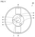
- FIG. 11 is a schematic bottom view showing the configuration of the holder 300.
- the configuration of the holder 300 as viewed in the first direction 101 is shown.
- a plurality of discharge ports 98 are formed in the holder 300.
- the plurality of discharge ports 98 are provided in the second front end face 96.
- the discharge ports 98 are openings through which the cutting fluid is discharged.
- the number of discharge ports 98 is, for example, three.
- the plurality of discharge ports 98 are positioned, for example, three-fold symmetrically with respect to the axis A.
- the holder 300 has, for example, two protrusions 88.
- the insertion portion 85 is located between the two protrusions 88.
- FIG. 12 is a schematic cross-sectional view taken along line XII-XII in FIG. 10.
- the cross section shown in FIG. 12 is perpendicular to axis A and passes between the first member 10 and the holder 300.
- the discharge port 98 projected onto the cross section is shown by a dashed line.
- the first member 10, the second member 20, and the support member 30 form at least one inlet 99.
- the first member 10, the second member 20, and the support member 30 form, for example, three inlets 99.
- the inlet 99 is located between the insertion hole 95 (see FIG. 3) and the space 92 (see FIG. 3).
- the inlet 99 connects the insertion hole 95 and the space 92.
- the discharge ports 98 overlap with the inlets 99. Specifically, when viewed along the axis A, at least one discharge port 98 overlaps with at least one inlet 99. When viewed along the axis A, a portion of the discharge port 98 may overlap with the inclined surface 15. In the radial direction, the discharge port 98 is located between the first inner circumferential surface 12 and the second inner circumferential surface 22.
- one outlet port 98 overlaps one inlet port 99.
- the number of outlet ports 98 is, for example, the same as the number of inlets 99.
- the number of each of the outlet ports 98 and inlets 99 is not particularly limited.
- cutting fluid is supplied into the body 100.
- the cutting fluid flows from the holder 300 along the direction of a first arrow 131.
- the cutting fluid flows into the space 92 from the discharge port 98.
- the cutting fluid passes from the space 92 through the flow path 50 and is discharged to the outside of the body 100.
- FIG. 13 is an enlarged perspective schematic diagram showing the flow of cutting fluid around the cutting insert 200.
- the enlarged perspective schematic diagram shown in FIG. 13 corresponds to the enlarged perspective schematic diagram shown in FIG. 6.
- the cutting fluid discharged from the flow path 50 flows toward the cutting insert 200 along the second arrow 132. In this way, cutting fluid is supplied to the cutting insert 200.
- the cutting tool 500 has a first member 10 and a second member 20.
- a space 92 is formed between the first member 10 and the second member 20.
- the space 92 surrounds the first through hole 91.
- a flow path 50 is formed that is connected to the space 92 and opens at the second outer surface 21. Therefore, the cutting fluid supplied into the body 100 flows into the space 92. This reduces the flow rate of the cutting fluid flowing out of the first through hole 91. This prevents the cutting fluid from flowing out of the body 100 through the first through hole 91.
- the flow rate of cutting fluid discharged from the second outer peripheral surface 21 can be increased compared to when the space 92 is not formed.
- the space 92 functions as a flow path exclusively for the cutting fluid. Therefore, the pressure loss of the cutting fluid flow can be reduced compared to a case where the space 92 is not formed.
- the cutting fluid can be temporarily held in the space 92 before it flows into the flow passages 50. This makes it possible to equalize the flow rate of the cutting fluid flowing from the space 92 into each of the multiple flow passages 50. As a result, it is possible to equalize the flow rate of the cutting fluid discharged from each of the multiple flow passages 50.
- the body 100 has a support member 30.
- the support member 30 connects the first outer peripheral surface 11 and the second inner peripheral surface 22.
- the support member 30 is spaced apart from each of the first front end surface 1 and the first rear end surface 2. Therefore, vibrations of each of the first member 10 and the second member 20 can be suppressed when cutting is performed using the cutting tool 500.
- the third flow path portion 53 is curved when viewed along the axis A. This improves the design freedom of the third flow path portion 53 while reducing the pressure loss of the cutting fluid flowing through the third flow path portion 53.
- the flow passage 50 has a first flow passage portion 51.
- the first flow passage portion 51 opens toward the rake face 81. This allows the cutting edge 84 connected to the rake face 81 to be effectively cooled.
- the flow passage 50 has a third flow passage portion 53.
- the third flow passage portion 53 opens toward the flank 82. Therefore, the cutting edge 84 connected to the flank 82 can be effectively cooled.
- the first member 10 has a first inner circumferential surface 12.
- the first inner circumferential surface 12 has a second inner circumferential surface portion 14.
- the diameter of the second inner circumferential surface portion 14 decreases as it moves away from the first front end surface 1.
- the second inner circumferential surface portion 14 is inclined with respect to a direction perpendicular to the first direction 101. Therefore, when the stacking direction of the three-dimensional printer is the first direction 101, the amount of support material used in forming the second inner circumferential surface portion 14 can be reduced. As a result, the time required to form the body 100 can be reduced.
- At least one discharge port 98 is provided in the holder 300.
- At least one inlet 99 is formed in the body 100.
- at least one discharge port 98 overlaps with at least one inlet 99. Therefore, the distance between the discharge port 98 and the inlet 99 is shorter than when the discharge port 98 does not overlap with the inlet 99 when viewed along the axis A. This reduces the pressure loss of the cutting fluid when the cutting fluid discharged from the discharge port 98 flows toward the inlet 99.
- sampling preparation First, cutting tools 500 according to Sample 1 and Sample 2 were prepared.
- the cutting tool 500 according to Sample 1 is a comparative example.
- the cutting tool 500 according to Sample 2 is an example.
- the space 92 was not formed.
- the flow path 50 was connected to the first through hole 91.
- the cutting tool 500 of sample 2 was configured as shown in Figures 10 to 12. Specifically, in the cutting tool 500 of sample 2, the space 92 was formed.
- Table 1 shows the ratio of the discharge amount in each row of the cutting tool 500 for Sample 1 and Sample 2.
- the first row refers to the row that is closest to the first rear end surface 2 among the five rows.
- the four rows other than the first row are numbered from the second row to the fifth row in order from the first row toward the third direction 103.
- the ratio of the discharge amount of each of the first to fifth stages was 7% or more and 28% or less.
- the ratio of the discharge amount of each of the first to fifth stages was 18% or more and 21% or less.
Landscapes
- Engineering & Computer Science (AREA)
- Mechanical Engineering (AREA)
- Milling Processes (AREA)
- Cutting Tools, Boring Holders, And Turrets (AREA)
Priority Applications (4)
| Application Number | Priority Date | Filing Date | Title |
|---|---|---|---|
| CN202280101289.9A CN120152808A (zh) | 2022-11-02 | 2022-11-02 | 切削工具 |
| EP22964419.0A EP4613408A4 (en) | 2022-11-02 | 2022-11-02 | CUTTING TOOL |
| PCT/JP2022/041008 WO2024095399A1 (ja) | 2022-11-02 | 2022-11-02 | 切削工具 |
| JP2023512674A JP7343076B1 (ja) | 2022-11-02 | 2022-11-02 | 切削工具 |
Applications Claiming Priority (1)
| Application Number | Priority Date | Filing Date | Title |
|---|---|---|---|
| PCT/JP2022/041008 WO2024095399A1 (ja) | 2022-11-02 | 2022-11-02 | 切削工具 |
Publications (1)
| Publication Number | Publication Date |
|---|---|
| WO2024095399A1 true WO2024095399A1 (ja) | 2024-05-10 |
Family
ID=87934850
Family Applications (1)
| Application Number | Title | Priority Date | Filing Date |
|---|---|---|---|
| PCT/JP2022/041008 Ceased WO2024095399A1 (ja) | 2022-11-02 | 2022-11-02 | 切削工具 |
Country Status (4)
| Country | Link |
|---|---|
| EP (1) | EP4613408A4 (https=) |
| JP (1) | JP7343076B1 (https=) |
| CN (1) | CN120152808A (https=) |
| WO (1) | WO2024095399A1 (https=) |
Cited By (1)
| Publication number | Priority date | Publication date | Assignee | Title |
|---|---|---|---|---|
| WO2026025470A1 (en) * | 2024-08-02 | 2026-02-05 | Safran Aircraft Engines Suzhou Co., Ltd. | Cutting tool |
Families Citing this family (1)
| Publication number | Priority date | Publication date | Assignee | Title |
|---|---|---|---|---|
| DE102023211880A1 (de) * | 2023-11-28 | 2025-05-28 | Kennametal Inc. | Werkzeug, Schneidanordnung für ein Werkzeug und Verfahren zur Herstellung eines Werkzeugs |
Citations (7)
| Publication number | Priority date | Publication date | Assignee | Title |
|---|---|---|---|---|
| JP2010234457A (ja) | 2009-03-30 | 2010-10-21 | Mitsubishi Materials Corp | インサート着脱式切削工具 |
| JP2018149655A (ja) * | 2017-03-14 | 2018-09-27 | 三菱マテリアル株式会社 | 刃先交換式切削工具用ホルダおよび刃先交換式切削工具 |
| JP2018149656A (ja) * | 2017-03-14 | 2018-09-27 | 三菱マテリアル株式会社 | 刃先交換式切削工具用ホルダおよび刃先交換式切削工具 |
| JP2020163544A (ja) * | 2019-03-29 | 2020-10-08 | 三菱マテリアル株式会社 | 切削インサートおよび転削工具 |
| US20210101214A1 (en) * | 2019-10-08 | 2021-04-08 | Kennametal Inc. | Cutting Tool |
| US20210220956A1 (en) * | 2020-01-22 | 2021-07-22 | Kennametal Inc. | Indexable milling cutter with precise coolant streams |
| CN214079467U (zh) * | 2020-10-19 | 2021-08-31 | 松德刀具(长兴)科技有限公司 | 一种玉米铣刀 |
Family Cites Families (4)
| Publication number | Priority date | Publication date | Assignee | Title |
|---|---|---|---|---|
| DE202004008642U1 (de) * | 2004-05-27 | 2005-09-29 | Kennametal Inc. | Fräswerkzeug |
| US8573098B2 (en) * | 2011-03-07 | 2013-11-05 | Kennametal Inc. | Cutting tool including a locking screw and adapter with coolant delivery |
| CN110587003A (zh) * | 2019-10-08 | 2019-12-20 | 哈尔滨理工大学 | 一种低温微量润滑切削加工混合喷液式盘铣刀 |
| JP2021160023A (ja) * | 2020-03-31 | 2021-10-11 | 三菱マテリアル株式会社 | 刃先交換式切削工具および工具本体 |
-
2022
- 2022-11-02 WO PCT/JP2022/041008 patent/WO2024095399A1/ja not_active Ceased
- 2022-11-02 CN CN202280101289.9A patent/CN120152808A/zh active Pending
- 2022-11-02 JP JP2023512674A patent/JP7343076B1/ja active Active
- 2022-11-02 EP EP22964419.0A patent/EP4613408A4/en active Pending
Patent Citations (7)
| Publication number | Priority date | Publication date | Assignee | Title |
|---|---|---|---|---|
| JP2010234457A (ja) | 2009-03-30 | 2010-10-21 | Mitsubishi Materials Corp | インサート着脱式切削工具 |
| JP2018149655A (ja) * | 2017-03-14 | 2018-09-27 | 三菱マテリアル株式会社 | 刃先交換式切削工具用ホルダおよび刃先交換式切削工具 |
| JP2018149656A (ja) * | 2017-03-14 | 2018-09-27 | 三菱マテリアル株式会社 | 刃先交換式切削工具用ホルダおよび刃先交換式切削工具 |
| JP2020163544A (ja) * | 2019-03-29 | 2020-10-08 | 三菱マテリアル株式会社 | 切削インサートおよび転削工具 |
| US20210101214A1 (en) * | 2019-10-08 | 2021-04-08 | Kennametal Inc. | Cutting Tool |
| US20210220956A1 (en) * | 2020-01-22 | 2021-07-22 | Kennametal Inc. | Indexable milling cutter with precise coolant streams |
| CN214079467U (zh) * | 2020-10-19 | 2021-08-31 | 松德刀具(长兴)科技有限公司 | 一种玉米铣刀 |
Non-Patent Citations (1)
| Title |
|---|
| See also references of EP4613408A4 |
Cited By (1)
| Publication number | Priority date | Publication date | Assignee | Title |
|---|---|---|---|---|
| WO2026025470A1 (en) * | 2024-08-02 | 2026-02-05 | Safran Aircraft Engines Suzhou Co., Ltd. | Cutting tool |
Also Published As
| Publication number | Publication date |
|---|---|
| JPWO2024095399A1 (https=) | 2024-05-10 |
| EP4613408A4 (en) | 2026-01-14 |
| JP7343076B1 (ja) | 2023-09-12 |
| CN120152808A (zh) | 2025-06-13 |
| EP4613408A1 (en) | 2025-09-10 |
Similar Documents
| Publication | Publication Date | Title |
|---|---|---|
| EP2946857B1 (en) | Turning tool holder and cutting tool insert | |
| WO2024095399A1 (ja) | 切削工具 | |
| KR102307031B1 (ko) | 일체 형성된 냉각제 편향부를 갖는 냉각 챔버 및 공구 몸체를 갖는 절삭 공구 | |
| JP2024097067A (ja) | シェルエンドミル用工具本体及び切削工具 | |
| JP6955107B2 (ja) | ワークピースを機械加工するための工具 | |
| JP2016135524A (ja) | バイト | |
| JP6621044B1 (ja) | 切削インサートおよびフライス工具 | |
| WO2016121870A1 (ja) | 切削工具及び切削加工物の製造方法 | |
| RU2738868C1 (ru) | Инструмент для вихревой обработки | |
| US12515264B2 (en) | Milling tool with coolant distributing holes | |
| JP2022519440A (ja) | 座面が複数の当接要素を備えるインサート・ポケットを有する回転切削体、回転切削工具及びインサート | |
| US20230063846A1 (en) | Cutting tool | |
| EP3098006A1 (en) | Cutter head | |
| JP6874292B2 (ja) | バイト | |
| US20250058384A1 (en) | Drill body of an indexable insert drill and indexable insert drill comprising such a drill body | |
| JP7310090B2 (ja) | 油孔付きドリル | |
| JP2025503386A (ja) | フライス加工工具及びフライス加工工具のための冷却剤スリーブ | |
| CN115722708B (zh) | 切削工具 | |
| JP7746403B2 (ja) | ホルダ、切削工具及び切削加工物の製造方法 | |
| JP7575647B1 (ja) | 切削インサートおよび回転切削工具 | |
| JP2021160023A (ja) | 刃先交換式切削工具および工具本体 | |
| JP7747874B2 (ja) | ボーリング工具および切削加工物の製造方法 | |
| JPWO2024195286A5 (https=) | ||
| JP2021160021A (ja) | 刃先交換式切削工具および工具本体 |
Legal Events
| Date | Code | Title | Description |
|---|---|---|---|
| ENP | Entry into the national phase |
Ref document number: 2023512674 Country of ref document: JP Kind code of ref document: A |
|
| 121 | Ep: the epo has been informed by wipo that ep was designated in this application |
Ref document number: 22964419 Country of ref document: EP Kind code of ref document: A1 |
|
| WWE | Wipo information: entry into national phase |
Ref document number: 202280101289.9 Country of ref document: CN |
|
| WWE | Wipo information: entry into national phase |
Ref document number: 2022964419 Country of ref document: EP |
|
| NENP | Non-entry into the national phase |
Ref country code: DE |
|
| ENP | Entry into the national phase |
Ref document number: 2022964419 Country of ref document: EP Effective date: 20250602 |
|
| WWP | Wipo information: published in national office |
Ref document number: 202280101289.9 Country of ref document: CN |
|
| WWP | Wipo information: published in national office |
Ref document number: 2022964419 Country of ref document: EP |