WO2024095320A1 - 回転電機 - Google Patents
回転電機 Download PDFInfo
- Publication number
- WO2024095320A1 WO2024095320A1 PCT/JP2022/040740 JP2022040740W WO2024095320A1 WO 2024095320 A1 WO2024095320 A1 WO 2024095320A1 JP 2022040740 W JP2022040740 W JP 2022040740W WO 2024095320 A1 WO2024095320 A1 WO 2024095320A1
- Authority
- WO
- WIPO (PCT)
- Prior art keywords
- electric machine
- rotor core
- rotating electric
- mass body
- guide
- Prior art date
- Legal status (The legal status is an assumption and is not a legal conclusion. Google has not performed a legal analysis and makes no representation as to the accuracy of the status listed.)
- Ceased
Links
Images







Classifications
-
- H—ELECTRICITY
- H02—GENERATION; CONVERSION OR DISTRIBUTION OF ELECTRIC POWER
- H02K—DYNAMO-ELECTRIC MACHINES
- H02K1/00—Details of the magnetic circuit
- H02K1/06—Details of the magnetic circuit characterised by the shape, form or construction
- H02K1/22—Rotating parts of the magnetic circuit
-
- H—ELECTRICITY
- H02—GENERATION; CONVERSION OR DISTRIBUTION OF ELECTRIC POWER
- H02K—DYNAMO-ELECTRIC MACHINES
- H02K7/00—Arrangements for handling mechanical energy structurally associated with dynamo-electric machines, e.g. structural association with mechanical driving motors or auxiliary dynamo-electric machines
- H02K7/04—Balancing means
Definitions
- This disclosure relates to a rotating electric machine having end plates at both axial ends of a rotor core.
- Patent Document 1 shows a pendulum damper including a support member including two annular plates fixed to a rotor, and a plurality of pendulum balance weights arranged between the annular plates of the support member.
- the two annular plates have openings as guide tracks having an epicycloidal shape, and a guide roller is engaged with the pendulum balance weight. The end of the guide roller is guided by the openings of the two annular plates, so that the pendulum balance weight vibrates between the two annular plates that are the support members.
- Patent Document 1 also shows that in order to incorporate the pendulum damper into the rotor structure, a part of the assembly of sheet metal of the rotor is cut out to provide an accommodation space for the pendulum balance weight, and the annular plates of the support member are arranged on both axial sides of the accommodation space.
- Patent Document 1 multiple pendulum balance weights are provided in a portion of the axial area of the rotor, so in order to increase the weight of the pendulum balance weights to effectively reduce vibration and noise caused by torque ripple, it is necessary to increase the volume of the rotor, which poses a challenge in promoting the miniaturization of rotors and rotating electrical machines.
- This disclosure was made in consideration of the above, and aims to provide a rotating electric machine that can suppress vibrations and noise caused by torque ripple without increasing the volume of the rotor.
- the rotating electric machine of the present disclosure includes a rotor and a stator.
- the rotor includes a rotor core having a shaft hole, a plurality of permanent magnets provided on the outer periphery of the rotor core, a plurality of through holes provided between the shaft hole and the plurality of permanent magnets, a plurality of mass bodies having a first guide body which is one of a convex portion and a concave portion at both ends and inserted into the plurality of through holes, and a pair of end plates provided on both ends of the rotor core and having a plurality of second guide bodies which are the other of the convex portions and the concave portions.
- the oscillation of the mass bodies relative to the rotor core is guided by the sliding of the first guide body relative to the second guide body.
- the rotating electric machine disclosed herein has the advantage of being able to suppress vibrations and noise caused by torque ripple without increasing the volume of the rotor.
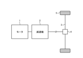
- FIG. 1 is a block diagram showing a configuration example of a drive train of an electric vehicle to which the rotating electric machine according to the first to fourth embodiments is applied;
- FIG. 1 is a plan view showing a configuration of a rotating electric machine according to first to fourth embodiments;
- FIG. 1 is an enlarged plan view showing a configuration in which a part of a rotating electric machine according to first to fourth embodiments is enlarged.
- FIG. 1 is a perspective view showing a configuration of a rotor of a rotating electric machine according to a first embodiment;
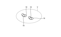
- FIG. 1 is an enlarged view showing a configuration in which a part of a rotor of a rotating electric machine according to a first embodiment is enlarged;
- FIG. 1 is a block diagram showing a configuration example of a drive train of an electric vehicle to which the rotating electric machine according to the first to fourth embodiments is applied;
- FIG. 1 is a plan view showing a configuration of a rotating electric machine according to first to fourth embodiments;
- FIG. 1 is an
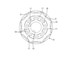
- FIG. 1 is a plan view showing a configuration of a rotor core of a rotating electric machine according to a first embodiment
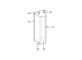
- FIG. 1 is a perspective view showing a configuration of a pendulum mass body of a rotating electric machine according to a first embodiment
- FIG. 1 is a plan view showing a positional relationship between a weight reduction hole and a mass body of a rotating electric machine according to a first embodiment
- FIG. 11 is a plan view showing a configuration of a rotor core of a rotating electric machine according to a second embodiment of the present invention
- FIG. 11 is a perspective view showing a configuration of an end plate of a rotating electric machine according to a second embodiment
- FIG. 11 is a perspective view showing a configuration of a pendulum mass body of a rotating electric machine according to a third embodiment
- FIG. 13 is a perspective view showing a configuration of an end plate of a rotating electric machine according to a third embodiment
- FIG. 13 is a perspective view showing a configuration of a rotor of a rotating electric machine according to a fourth embodiment.
- FIG. 13 is a perspective view showing a configuration of a back surface of one end plate of a rotating electric machine according to a fourth embodiment, the back surface facing a rotor core
- FIG. 13 is a perspective view showing the configuration of the front surface of the other end plate of the rotating electric machine according to the fourth embodiment
- FIG. 13 is a plan view showing a partial configuration of a rear surface of one end plate of a rotating electric machine according to a fourth embodiment;
- FIG. 1 is a block diagram showing an example of the configuration of a drive train of an electric vehicle to which the rotating electric machine of embodiments 1 to 4 is applied.
- the electric vehicle shown in FIG. 1 has, as its main components, a motor 1 as a rotating electric machine, a reduction gear 2, a drive shaft 3, a differential gear 4, and driving wheels 5.
- the motor 1 has a rotor that functions as a pendulum damper.
- the motor 1 rotates by receiving power from an inverter (not shown) and generates motor torque.
- the motor 1 is a synchronous motor whose rotor rotates in a rotating magnetic field of three-phase AC.
- the motor 1 has a rotor with a permanent magnet embedded therein, a stator made of an electromagnet, and a motor case (not shown) that houses the stator and rotor.
- the reducer 2 arranged on the output side of the motor 1 transmits torque between the motor 1 and the drive wheels 5.
- the reducer 2 is provided between the motor 1 and the drive wheels 5 on the power transmission path.
- the reducer 2 is a mechanism that can appropriately change the gear ratio, which is the ratio of the rotation speed of the output shaft to the rotation speed of the input shaft.
- the differential gear 4 is a differential device that detects the difference in the rotation speed of the two drive wheels 5 and distributes and transmits the torque of the reducer 2 to each drive wheel 5.
- the differential gear 4 transmits the torque transmitted from the reducer 2 to the drive wheels 5.
- the drive wheels 5 are wheels to which the drive torque output by the drive power source is transmitted and which generate the drive force of the electric vehicle.
- FIG. 2 is a plan view showing the configuration of the rotating electric machine of the first to fourth embodiments.
- FIG. 3 is an enlarged plan view showing the configuration of a part of the rotating electric machine of the first to fourth embodiments.
- FIG. 2 and FIG. 3 show the components common to the first to fourth embodiments.
- the motor 1 has a rotor 6 and a stator 7.
- the rotor 6 is arranged inside the stator 7.
- the torque generated by the motor 1 is amplified and attenuated by the connected reducer 2 and transmitted to the drive wheels 5. Therefore, the torque ripple generated by the motor 1 is transmitted to the drive shaft 3, causing vibration and noise in the entire electric vehicle.
- the rotor 6 has a rotor core 8, a permanent magnet 9, an end plate, and a pendulum mass body.
- the end plate and the pendulum mass body will be described later.
- the rotor core 8 may be made of a laminate of electromagnetic steel sheets, or may be made of other materials such as a powder core made by pressure
- the motor 1 is an interior permanent magnet synchronous motor (IPMSM) with permanent magnets 9 embedded inside the rotor core 8.
- IPMSM interior permanent magnet synchronous motor
- the rotor core 8 has a plurality of magnet insertion holes 10 for embedding the plurality of permanent magnets 9 on its outer periphery.
- the rotor core 8 has a shaft hole 12 through which a shaft (not shown) that connects the motor 1 and the reducer 2 passes.
- the rotor core 8 also has a plurality of weight reduction holes 11, which are through holes for reducing the weight of the rotor core 8 and improving the magnetic flux density while maintaining the strength to withstand the centrifugal force generated in the rotor core 8 and the permanent magnets 9.
- the weight reduction holes 11 are provided between the plurality of permanent magnets 9 and the shaft hole 12.
- Each weight reduction hole 11 is a through hole.
- an interpole bridge 13 extending radially inward from the outer circumferential surface of the rotor core 8, and an interpole gap (flux barrier) 14, which is a gap for preventing magnetic flux short circuits.
- the interpole gap 14 is a gap formed in the magnet insertion hole 10, and the tip of the interpole gap 14 is rounded, for example, in a semi-elliptical shape 15.
- Fig. 4 is a perspective view showing the configuration of the rotor 6 of the rotating electric machine according to the first embodiment.
- Fig. 5 is an enlarged view showing the configuration of a part of the rotor 6 of the rotating electric machine according to the first embodiment.
- Fig. 5 shows an enlarged view of the V part of Fig. 4.
- Fig. 6 is a plan view showing the configuration of the rotor core 8 of the rotating electric machine according to the first embodiment.
- Fig. 7 is a perspective view showing the configuration of the pendulum mass body 17 of the rotating electric machine according to the first embodiment.
- the rotor 6 has a rotor core 8 and a pair of end plates 16.
- the end plates 16 are disposed at both ends of the rotor core 8 to prevent misalignment of the rotor core 8 and the permanent magnets 9 and to ensure the rotational balance of the rotor core 8.
- the end plates 16 are provided with a shaft hole 20 for passing the shaft through, and the inner diameter of the shaft hole 20 matches the inner diameter of the shaft hole 12 of the rotor core 8. To prevent the shaft from being separated from the rotor core 8 and the end plates 16 due to rotation, these components are fixed by press fitting, but they may also be fixed with a key structure.
- the end plate 16 is made of a non-magnetic material to reduce the effect on the magnetic flux.
- the end plate 16 has a guide hole 19 as a second guide body for determining the swing trajectory of the pendulum mass body 17 (described later) provided in the rotor core 8.
- the guide hole 19 is a through hole.
- the guide hole 19 may also be a blind hole with a bottom. Through holes and blind holes are collectively referred to as a recess.
- a plurality of guide holes 19 are arranged along the circumferential direction of the end plate 16. Specifically, the guide holes 19 are arranged in multiple sets of two as shown in FIG. 5.
- a pendulum mass 17 is embedded in the weight reduction hole 11 of the rotor core 8.
- the pendulum mass 17 is also simply called the mass 17.
- the mass 17 includes a weight portion 21 and a protrusion 18.
- the weight portion 21 has a length that is, for example, the entire axial length of the weight reduction hole 11, which is a through hole. Both ends of the mass 17 inserted into the weight reduction hole 11 have protrusions 18 as first guide bodies for restraining the swing trajectory in the guide hole 19 of the end plate 16.
- the protrusion 18, which is a convex portion is fixed to the weight portion 21 and has, for example, a cylindrical shape.
- the protrusion 18 may have any other shape, such as a hexagonal column.
- the protrusion 18 may also have a fixed axis or a central axis that can rotate freely.
- two protrusions 18 are provided on each side of each mass body 17 to suppress rotational movement of the mass body 17 around its axis and promote sliding of the mass body 17.
- pairs of guide holes 19, which are paired with the mass body 17 having two protrusions 18 on one side, are arranged in the circumferential direction on the end plate 16 in the same number as the mass body 17.
- the pair of guide holes 19 are arranged so as to be mirror-symmetrical with respect to a radial line passing through the center of the pair of guide holes 19.
- one protrusion 18 may be arranged on each side of each mass body 17.
- the cross section of the protrusions 18 is not limited to a circular shape, and may be any curved or polygonal shape.
- FIG. 8 is a plan view showing the positional relationship between the weight reduction hole 11 and the mass body 17 of the rotating electric machine of the first embodiment.
- the cross-sectional shape of the weight portion 21 of the mass body 17 is similar to the cross-sectional shape of the weight reduction hole 11. This is to increase the inertia of the mass body 17.
- the cross-sectional shapes of the weight portion 21 and the weight reduction hole 11 are set so that a gap is generated between the mass body 17 and the inner wall of the weight reduction hole 11 of the rotor core 8 at all positions on the orbit, as shown in FIG. 8. If there is no gap between the mass body 17 and the inner wall of the weight reduction hole 11, not only will the desired vibration damping effect not be obtained due to nonlinear behavior caused by a collision, but abnormal noise may also be generated and the rotor core 8 may be deformed.
- the axial length L1 of the weight portion 21 of the mass body 17 is set shorter than the axial length Lr of the rotor core 8, and the overall length Lt of the pendulum mass body 17 including the protrusions 18 is desirably designed to be slightly smaller than Lr + 2Lp, which is the total length of the axial length Lr of the rotor core 8 and the thickness Lp of the end plates 16 connected to both ends of the rotor core 8. This prevents interference with the reducer 2, the motor case, etc.
- the mass body 17 is made of a non-magnetic material to reduce its effect on the magnetic flux.
- the mass body 17 may be a magnetic material (conductor), in which case, when the mass body 17 moves to a position of high magnetic flux density due to electromagnetic induction, a damping effect is generated, preventing excessive displacement of the weight portion 21 and reducing abnormal noise that occurs when the protrusion 18 comes into contact with the end of the guide hole 19.
- the orbit radius of the swing orbit of the mass body 17 is determined by the order of rotation that causes the cogging torque or torque ripple vibration according to the number of pole pairs of the motor 1.
- the swing orbit of the mass body 17 may be a circular orbit, or may be determined by a higher order function to prevent unstable behavior of the pendulum.
- the rotation radius L of the swing orbit of the mass body 17 and the distance R between the center of rotation of the swing orbit of the mass body 17 and the center of the rotor core 8 are set so that the effective rotation order that produces the effect as a vibration absorber in a rotating electric machine composed of a three-phase AC synchronous motor coincides with the frequency obtained by multiplying the number of pole pairs N of the permanent magnet 9 by the sixth order frequency component that is the main frequency component of the torque ripple of the three-phase AC synchronous motor.
- Cogging is a pulsating torque caused by the magnetic field generated between the rotor core 8 and permanent magnets 9 when the motor 1 is not energized, and its magnitude is constant regardless of the current when the motor 1 is energized. It is generally known that the lower the rotation speed of the motor 1, the greater the pulsating torque becomes, and that increasing the rotation speed increases the inertial force acting on the rotor core 8, resulting in a relatively smaller pulsating torque.
- Torque ripple corresponds to the fluctuation in electromagnetic torque generated by the field flux of the permanent magnets 9 and the current in the coil when the motor 1 is energized, and its magnitude is said to be proportional to the current.
- the center of the weight reduction hole 11 is located at a position that overlaps with the d-axis or q-axis, and is located at a position that does not interfere with the magnet insertion hole 10 into which the permanent magnet 9 is inserted. If the center of the weight reduction hole 11 is not located on the d-axis or q-axis, the distribution of the interlinkage magnetic flux becomes asymmetric with respect to the d-axis and q-axis, and the spatial harmonic components of the magnetic flux increase. This increases iron loss, radial electromagnetic force, and torque ripple. To prevent this, the center of the weight reduction hole 11 is located at a position that overlaps with the d-axis or q-axis.
- the rotor core 8 is provided with the weight-reducing holes 11, which are through holes, the mass body 17 is arranged so as to penetrate the rotor core 8, protrusions 18 are provided at both ends of the mass body 17 as first guide bodies, and the end plate 16 is provided with guide holes 19 as second guide bodies, and the sliding of the protrusions 18 relative to the guide holes 19 guides the oscillation of the mass body 17 relative to the rotor core 8. This makes it possible to suppress vibrations and noise due to torque ripple without increasing the volume of the rotor 6.
- Embodiment 2 is a plan view showing the configuration of rotor core 8 of a rotating electric machine according to embodiment 2.
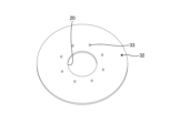
- Fig. 10 is a perspective view showing the configuration of an end plate 32 of a rotating electric machine according to embodiment 2.
- mass body 17 of embodiment 1 is replaced with mass body 30, and end plate 16 of embodiment 1 is replaced with end plate 32.
- Other configurations in embodiment 2 are similar to those in embodiment 1, and repeated explanations will be omitted.
- guide grooves 31, which are recesses that define the swing trajectory, are provided at both ends of each mass body 30.
- the guide grooves 31 correspond to the first guide body.
- a plurality of protrusions 33, which are convex portions, are provided intermittently in the circumferential direction on each end plate 32.
- the protrusions 33 correspond to the second guide body.
- one protrusion 33 is provided corresponding to each guide groove 31, and each protrusion 33 slides within each guide groove 31.
- the mass body 30 slides and at the same time rotates around the axis of the protrusion 33.
- the axial center of the protrusion 33 is eccentric and offset from the center of gravity (center) of the mass body 30. If the guide groove 31 is provided radially outward from the center position of the mass body 30, there is a possibility that the mass body 30 will collide with the inner wall of the weight reduction hole 11 when it rotates around its axis. To prevent this, according to embodiment 2, the guide groove 31 is provided radially inward from the center position of the mass body 30.
- the guide grooves 31 are provided radially inward from the center position of the mass body 30, so that even if one protrusion 33 is provided corresponding to each guide groove 31, interference with the weight reduction hole 11 due to rotation of the mass body 30 can be prevented.
- Fig. 11 is a perspective view showing a configuration of a pendulum mass body 41 of a rotating electric machine according to the third embodiment.
- Fig. 12 is a perspective view showing a configuration of an end plate 46 of a rotating electric machine according to the third embodiment.
- the pendulum mass body 41 includes a first mass body 41a including a weight portion 43a having projections 42a as first projections at both ends, a second mass body 41b including a weight portion 43b having projections 42b as second projections at both ends, and a connecting member 45 connecting the projections 42a and 42b.
- the first mass body 41a is inserted into the weight reduction hole 11 as a first through hole
- the second mass body 41b is inserted into the weight reduction hole 11 as a second through hole.
- the end plate 46 is formed with two guide holes 47, which are through holes that guide the two protrusions 42a and 42b of the pendulum mass body 41, and a recess 48 that connects the two guide holes 47 and serves as a third recess that accommodates the connecting member 45 of the pendulum mass body 41.
- One of the two guide holes 47 corresponds to the first recess, and the other corresponds to the second recess.
- the end plate 46 is provided with four sets of configurations having two guide holes 47 and recesses 48 in order to support the four pendulum mass bodies 41.
- the other configurations in the third embodiment are the same as those in the first embodiment, and redundant explanations will be omitted.
- the lightening hole 11 in the third embodiment is not shown, it is preferable that the lightening hole 11 has a shape similar to the cross-sectional shape of the weights 43a and 43b, as in the lightening hole 11 in the first embodiment.
- the protrusion 42a of the first mass 41a and the protrusion 42b of the second mass 41b are connected by a connecting member 45 to form a single pendulum mass 41.
- the connecting member 45 connects the tips of the protrusions 42a and 42b of the first mass 41a and the second mass 41b.
- the connecting member 45 has the effect of preventing the mass 41 from rotating around the protrusions 42a and 42b. Furthermore, as shown in Figures 4 and 8, if two guide holes 19 can be arranged corresponding to one weight reduction hole 11, the mass 41 can be prevented from rotating. However, even if only one guide hole 19 can be arranged corresponding to one weight reduction hole 11, this configuration can prevent the mass 41 from rotating and promote the sliding of the mass 41.
- the recess 48 is provided in the end plate 46, so that the connecting member 45 can be prevented from being exposed.
- the pair of guide holes 47 are arranged in mirror symmetry with respect to a radial line that passes through the middle of the pair of guide holes 47. This allows the mass body 41 to perform pendulum motion with the positional relationship of the axes of the two protrusions 42a, 42b fixed.
- the pendulum mass 41 is formed by connecting the first mass 41a and the second mass 41b with the connecting member 45, which prevents the mass 41 from rotating and promotes the sliding of the mass 41.
- FIG. 13 is a perspective view showing the configuration of the rotor 6 of the rotating electric machine of the fourth embodiment.
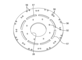
- FIG. 14 is a perspective view showing the configuration of the back surface of one end plate 51 of the rotating electric machine of the fourth embodiment, which faces the rotor core 8.
- FIG. 15 is a perspective view showing the configuration of the front surface of the other end plate 56 of the rotating electric machine of the fourth embodiment.
- FIG. 16 is a plan view showing a partial configuration of the back surface of one end plate 51 of the rotating electric machine of the fourth embodiment.
- one end plate 32 of the rotating electric machine of the second embodiment is replaced with an end plate 51
- the other end plate 32 of the rotating electric machine of the second embodiment is replaced with an end plate 56.
- the other configurations in the fourth embodiment are the same as those in the second embodiment, and redundant explanations will be omitted. That is, in the rotating electric machine of FIGS. 13 to 16, a plurality of protrusions 52 are arranged in the circumferential direction on the end plates 51 and 56, and a plurality of mass bodies 30 having a plurality of weight-reducing holes 11 and guide grooves 31 shown in FIG. 9 are provided in the rotor core 8 shown in FIG. In this way, the protrusions 52 in the fourth embodiment correspond to the protrusions 33 in the second embodiment.
- an end plate 51 is disposed at one end of the rotor core 8, and an end plate 56 is disposed at the other end of the rotor core 8.
- the end plate 51 has a flow path 53 for supplying lubricating oil to the protrusions 52 and the guide grooves 31, and the end plate 56 has discharge holes 57, 58 for discharging the lubricating oil supplied from the end plate 51.
- the lubricating oil may contain a coolant in addition to the lubricant.
- a flow path 53 is formed on the back surface of the end plate 51 as an oil groove.
- the flow path 53 reduces the contact friction of the protrusions 52 engaging with the guide grooves 31, and allows the flow of lubricating oil that cools the rotor core 8 as a whole.
- the flow path 53 has a plurality of grooves 53a extending from the shaft hole 20 on the inner periphery side of the end plate 51 to the protrusions 52, and a plurality of grooves 53b branching from the protrusions 52 and extending to the outer periphery of the end plate 51.
- the ends of the plurality of grooves 53b are provided at positions corresponding to the inter-pole gaps 14 formed in the rotor core 8.
- the lubricating oil that flows in from the shaft hole 20 flows into the protrusions 52 and guide grooves 31 via the plurality of grooves 53a, as shown by the arrows in FIG. 16, and a portion of the lubricating oil flows into the inside of the weight reduction hole 11 of the rotor core 8 into which the mass body 30 is inserted.
- the remaining lubricating oil flows through groove 53b while branching, as shown by the arrows in Figure 16, and reaches tip 55 of groove 53b, and then flows into inter-pole gap 14 of rotor core 8.
- the end plate 56 has a plurality of discharge holes 57 provided at positions corresponding to the plurality of weight reduction holes 11 of the rotor core 8, and a plurality of discharge holes 58 provided at positions corresponding to the plurality of inter-pole gaps 14 of the rotor core 8.
- the lubricating oil that flows into the weight reduction holes 11 of the rotor core 8 from the end plate 51 on one side is discharged from the discharge holes 57 of the end plate 56.
- the lubricating oil that flows into the inter-pole gaps 14 of the rotor core 8 from the end plate 51 on one side is discharged from the discharge holes 58 of the end plate 56.
- the lubricating oil inside the weight reduction hole 11 is subjected to centrifugal force and flows out from the radially outer inner wall. Therefore, for efficient discharge, it is desirable to position the discharge hole 57 radially outward of the weight reduction hole 11.
- the lubricating oil is discharged radially outward of the rotor core 8, but the flow path configuration may also be such that the lubricating oil is recovered toward the shaft hole 20.
- an oil groove is provided to supply lubricating oil to the guide groove 31 and the protrusion 52 to dissipate frictional heat, thereby reducing frictional heat between the guide groove 31 and the protrusion 52 and promoting smooth rocking motion of the mass body 30.
Landscapes
- Engineering & Computer Science (AREA)
- Power Engineering (AREA)
- Iron Core Of Rotating Electric Machines (AREA)
Priority Applications (2)
| Application Number | Priority Date | Filing Date | Title |
|---|---|---|---|
| JP2024553944A JP7774741B2 (ja) | 2022-10-31 | 2022-10-31 | 回転電機 |
| PCT/JP2022/040740 WO2024095320A1 (ja) | 2022-10-31 | 2022-10-31 | 回転電機 |
Applications Claiming Priority (1)
| Application Number | Priority Date | Filing Date | Title |
|---|---|---|---|
| PCT/JP2022/040740 WO2024095320A1 (ja) | 2022-10-31 | 2022-10-31 | 回転電機 |
Publications (1)
| Publication Number | Publication Date |
|---|---|
| WO2024095320A1 true WO2024095320A1 (ja) | 2024-05-10 |
Family
ID=90929979
Family Applications (1)
| Application Number | Title | Priority Date | Filing Date |
|---|---|---|---|
| PCT/JP2022/040740 Ceased WO2024095320A1 (ja) | 2022-10-31 | 2022-10-31 | 回転電機 |
Country Status (2)
| Country | Link |
|---|---|
| JP (1) | JP7774741B2 (https=) |
| WO (1) | WO2024095320A1 (https=) |
Citations (3)
| Publication number | Priority date | Publication date | Assignee | Title |
|---|---|---|---|---|
| JPS5018909U (https=) * | 1973-06-15 | 1975-03-03 | ||
| JP2001186745A (ja) * | 1999-12-24 | 2001-07-06 | Fujitsu Ltd | 反力キャンセル装置 |
| JP2009050068A (ja) * | 2007-08-17 | 2009-03-05 | Kura Gijutsu Kenkyusho:Kk | 磁束分流制御回転電機システム |
-
2022
- 2022-10-31 WO PCT/JP2022/040740 patent/WO2024095320A1/ja not_active Ceased
- 2022-10-31 JP JP2024553944A patent/JP7774741B2/ja active Active
Patent Citations (3)
| Publication number | Priority date | Publication date | Assignee | Title |
|---|---|---|---|---|
| JPS5018909U (https=) * | 1973-06-15 | 1975-03-03 | ||
| JP2001186745A (ja) * | 1999-12-24 | 2001-07-06 | Fujitsu Ltd | 反力キャンセル装置 |
| JP2009050068A (ja) * | 2007-08-17 | 2009-03-05 | Kura Gijutsu Kenkyusho:Kk | 磁束分流制御回転電機システム |
Also Published As
| Publication number | Publication date |
|---|---|
| JPWO2024095320A1 (https=) | 2024-05-10 |
| JP7774741B2 (ja) | 2025-11-21 |
Similar Documents
| Publication | Publication Date | Title |
|---|---|---|
| CN103872869B (zh) | 多间隙式旋转电机 | |
| JP5722301B2 (ja) | 埋込磁石型同期電動機の回転子および埋込磁石型同期電動機 | |
| JP4449035B2 (ja) | 電動車両用の永久磁石回転電機 | |
| JP2007097387A (ja) | 回転電機 | |
| CN102244428A (zh) | 用于旋转电机的转子 | |
| JP2020120444A (ja) | 回転電機のロータおよび回転電機 | |
| JP5323592B2 (ja) | 永久磁石回転電機及びそれを用いた電動車両 | |
| CN101283499A (zh) | 旋转电机 | |
| JP2012161243A (ja) | 永久磁石回転電機 | |
| WO2015068846A1 (ja) | 回転電機 | |
| JP3550971B2 (ja) | 電動機 | |
| JP7774741B2 (ja) | 回転電機 | |
| WO2021002381A1 (ja) | モータおよびモータユニット | |
| WO2023199460A1 (ja) | 回転装置 | |
| JPWO2019097603A1 (ja) | 永久磁石式回転電機 | |
| WO2018070430A1 (ja) | 同期リラクタンス型回転電機 | |
| KR20250133942A (ko) | 회전자 및 전기 기계 | |
| CN114402505B (zh) | 转子、电机和用于减小转子的不平衡的方法 | |
| JP2020014368A (ja) | ブラシレスモータ及びブラシレスモータの製造方法 | |
| WO2019069547A1 (ja) | ロータ、モータおよび電動パワーステアリング装置 | |
| JP4890056B2 (ja) | 電動機 | |
| JP2012016112A (ja) | 車両用回転電機のエンドプレート | |
| WO2023286606A1 (ja) | 回転電機、電動ホイール及び車両 | |
| JP4545702B2 (ja) | 電動機 | |
| JP7810203B2 (ja) | ロータコア、ロータ、回転電機及び車両駆動用装置 |
Legal Events
| Date | Code | Title | Description |
|---|---|---|---|
| 121 | Ep: the epo has been informed by wipo that ep was designated in this application |
Ref document number: 22964343 Country of ref document: EP Kind code of ref document: A1 |
|
| WWE | Wipo information: entry into national phase |
Ref document number: 2024553944 Country of ref document: JP |
|
| NENP | Non-entry into the national phase |
Ref country code: DE |
|
| 122 | Ep: pct application non-entry in european phase |
Ref document number: 22964343 Country of ref document: EP Kind code of ref document: A1 |