WO2024090171A1 - 振動型アクチュエータ、光学機器および電子機器 - Google Patents
振動型アクチュエータ、光学機器および電子機器 Download PDFInfo
- Publication number
- WO2024090171A1 WO2024090171A1 PCT/JP2023/036462 JP2023036462W WO2024090171A1 WO 2024090171 A1 WO2024090171 A1 WO 2024090171A1 JP 2023036462 W JP2023036462 W JP 2023036462W WO 2024090171 A1 WO2024090171 A1 WO 2024090171A1
- Authority
- WO
- WIPO (PCT)
- Prior art keywords
- electrode
- piezoelectric material
- vibration actuator
- hole
- elastic body
- Prior art date
- Legal status (The legal status is an assumption and is not a legal conclusion. Google has not performed a legal analysis and makes no representation as to the accuracy of the status listed.)
- Ceased
Links
Images


Classifications
-
- H—ELECTRICITY
- H10—SEMICONDUCTOR DEVICES; ELECTRIC SOLID-STATE DEVICES NOT OTHERWISE PROVIDED FOR
- H10N—ELECTRIC SOLID-STATE DEVICES NOT OTHERWISE PROVIDED FOR
- H10N30/00—Piezoelectric or electrostrictive devices
- H10N30/20—Piezoelectric or electrostrictive devices with electrical input and mechanical output, e.g. functioning as actuators or vibrators
- H10N30/202—Piezoelectric or electrostrictive devices with electrical input and mechanical output, e.g. functioning as actuators or vibrators using longitudinal or thickness displacement combined with bending, shear or torsion displacement
- H10N30/2023—Piezoelectric or electrostrictive devices with electrical input and mechanical output, e.g. functioning as actuators or vibrators using longitudinal or thickness displacement combined with bending, shear or torsion displacement having polygonal or rectangular shape
-
- B—PERFORMING OPERATIONS; TRANSPORTING
- B06—GENERATING OR TRANSMITTING MECHANICAL VIBRATIONS IN GENERAL
- B06B—METHODS OR APPARATUS FOR GENERATING OR TRANSMITTING MECHANICAL VIBRATIONS OF INFRASONIC, SONIC, OR ULTRASONIC FREQUENCY, e.g. FOR PERFORMING MECHANICAL WORK IN GENERAL
- B06B1/00—Methods or apparatus for generating mechanical vibrations of infrasonic, sonic, or ultrasonic frequency
- B06B1/02—Methods or apparatus for generating mechanical vibrations of infrasonic, sonic, or ultrasonic frequency making use of electrical energy
- B06B1/06—Methods or apparatus for generating mechanical vibrations of infrasonic, sonic, or ultrasonic frequency making use of electrical energy operating with piezoelectric effect or with electrostriction
- B06B1/0644—Methods or apparatus for generating mechanical vibrations of infrasonic, sonic, or ultrasonic frequency making use of electrical energy operating with piezoelectric effect or with electrostriction using a single piezoelectric element
- B06B1/0651—Methods or apparatus for generating mechanical vibrations of infrasonic, sonic, or ultrasonic frequency making use of electrical energy operating with piezoelectric effect or with electrostriction using a single piezoelectric element of circular shape
-
- G—PHYSICS
- G02—OPTICS
- G02B—OPTICAL ELEMENTS, SYSTEMS OR APPARATUS
- G02B7/00—Mountings, adjusting means, or light-tight connections, for optical elements
- G02B7/02—Mountings, adjusting means, or light-tight connections, for optical elements for lenses
- G02B7/022—Mountings, adjusting means, or light-tight connections, for optical elements for lenses lens and mount having complementary engagement means, e.g. screw/thread
-
- G—PHYSICS
- G02—OPTICS
- G02B—OPTICAL ELEMENTS, SYSTEMS OR APPARATUS
- G02B7/00—Mountings, adjusting means, or light-tight connections, for optical elements
- G02B7/02—Mountings, adjusting means, or light-tight connections, for optical elements for lenses
- G02B7/04—Mountings, adjusting means, or light-tight connections, for optical elements for lenses with mechanism for focusing or varying magnification
-
- H—ELECTRICITY
- H02—GENERATION; CONVERSION OR DISTRIBUTION OF ELECTRIC POWER
- H02N—ELECTRIC MACHINES NOT OTHERWISE PROVIDED FOR
- H02N2/00—Electric machines in general using piezoelectric effect, electrostriction or magnetostriction
- H02N2/0005—Electric machines in general using piezoelectric effect, electrostriction or magnetostriction producing non-specific motion; Details common to machines covered by H02N2/02 - H02N2/16
- H02N2/001—Driving devices, e.g. vibrators
- H02N2/0015—Driving devices, e.g. vibrators using only bending modes
-
- H—ELECTRICITY
- H02—GENERATION; CONVERSION OR DISTRIBUTION OF ELECTRIC POWER
- H02N—ELECTRIC MACHINES NOT OTHERWISE PROVIDED FOR
- H02N2/00—Electric machines in general using piezoelectric effect, electrostriction or magnetostriction
- H02N2/02—Electric machines in general using piezoelectric effect, electrostriction or magnetostriction producing linear motion, e.g. actuators; Linear positioners ; Linear motors
- H02N2/026—Electric machines in general using piezoelectric effect, electrostriction or magnetostriction producing linear motion, e.g. actuators; Linear positioners ; Linear motors by pressing one or more vibrators against the driven body
-
- H—ELECTRICITY
- H02—GENERATION; CONVERSION OR DISTRIBUTION OF ELECTRIC POWER
- H02N—ELECTRIC MACHINES NOT OTHERWISE PROVIDED FOR
- H02N2/00—Electric machines in general using piezoelectric effect, electrostriction or magnetostriction
- H02N2/02—Electric machines in general using piezoelectric effect, electrostriction or magnetostriction producing linear motion, e.g. actuators; Linear positioners ; Linear motors
- H02N2/04—Constructional details
-
- H—ELECTRICITY
- H10—SEMICONDUCTOR DEVICES; ELECTRIC SOLID-STATE DEVICES NOT OTHERWISE PROVIDED FOR
- H10N—ELECTRIC SOLID-STATE DEVICES NOT OTHERWISE PROVIDED FOR
- H10N30/00—Piezoelectric or electrostrictive devices
- H10N30/20—Piezoelectric or electrostrictive devices with electrical input and mechanical output, e.g. functioning as actuators or vibrators
- H10N30/202—Piezoelectric or electrostrictive devices with electrical input and mechanical output, e.g. functioning as actuators or vibrators using longitudinal or thickness displacement combined with bending, shear or torsion displacement
- H10N30/2027—Piezoelectric or electrostrictive devices with electrical input and mechanical output, e.g. functioning as actuators or vibrators using longitudinal or thickness displacement combined with bending, shear or torsion displacement having cylindrical or annular shape
-
- H—ELECTRICITY
- H10—SEMICONDUCTOR DEVICES; ELECTRIC SOLID-STATE DEVICES NOT OTHERWISE PROVIDED FOR
- H10N—ELECTRIC SOLID-STATE DEVICES NOT OTHERWISE PROVIDED FOR
- H10N30/00—Piezoelectric or electrostrictive devices
- H10N30/20—Piezoelectric or electrostrictive devices with electrical input and mechanical output, e.g. functioning as actuators or vibrators
- H10N30/204—Piezoelectric or electrostrictive devices with electrical input and mechanical output, e.g. functioning as actuators or vibrators using bending displacement, e.g. unimorph, bimorph or multimorph cantilever or membrane benders
- H10N30/2047—Membrane type
-
- H—ELECTRICITY
- H10—SEMICONDUCTOR DEVICES; ELECTRIC SOLID-STATE DEVICES NOT OTHERWISE PROVIDED FOR
- H10N—ELECTRIC SOLID-STATE DEVICES NOT OTHERWISE PROVIDED FOR
- H10N30/00—Piezoelectric or electrostrictive devices
- H10N30/80—Constructional details
- H10N30/85—Piezoelectric or electrostrictive active materials
- H10N30/852—Composite materials, e.g. having 1-3 or 2-2 type connectivity
-
- H—ELECTRICITY
- H10—SEMICONDUCTOR DEVICES; ELECTRIC SOLID-STATE DEVICES NOT OTHERWISE PROVIDED FOR
- H10N—ELECTRIC SOLID-STATE DEVICES NOT OTHERWISE PROVIDED FOR
- H10N30/00—Piezoelectric or electrostrictive devices
- H10N30/80—Constructional details
- H10N30/85—Piezoelectric or electrostrictive active materials
- H10N30/853—Ceramic compositions
- H10N30/8536—Alkaline earth metal based oxides, e.g. barium titanates
-
- H—ELECTRICITY
- H10—SEMICONDUCTOR DEVICES; ELECTRIC SOLID-STATE DEVICES NOT OTHERWISE PROVIDED FOR
- H10N—ELECTRIC SOLID-STATE DEVICES NOT OTHERWISE PROVIDED FOR
- H10N30/00—Piezoelectric or electrostrictive devices
- H10N30/80—Constructional details
- H10N30/87—Electrodes or interconnections, e.g. leads or terminals
- H10N30/872—Interconnections, e.g. connection electrodes of multilayer piezoelectric or electrostrictive devices
- H10N30/874—Interconnections, e.g. connection electrodes of multilayer piezoelectric or electrostrictive devices embedded within piezoelectric or electrostrictive material, e.g. via connections
Definitions
- the present invention relates to a vibration actuator including an ultrasonic motor.
- a vibration actuator has a vibrator configured so that vibrations are excited in an elastic body joined to a piezoelectric element by applying an alternating voltage to the electromechanical energy conversion element such as a piezoelectric element.
- the vibration actuator is used as an ultrasonic motor that uses the driving force of the vibrations excited in the vibrator to move the vibrator relative to a contact body that is in pressure contact with the vibrator.
- Patent Document 1 discloses a method for manufacturing a vibrator used in a vibration type actuator. In one example, it discloses a process in which an elastic body (referred to as a diaphragm in the document) and a power supply member are bonded to a piezoelectric element, and then the elastic body is grounded and a polarization process is performed on the piezoelectric ceramic.
- an elastic body referred to as a diaphragm in the document
- a power supply member bonded to a piezoelectric element
- the elastic body is grounded and a polarization process is performed on the piezoelectric ceramic.
- poor polarization may occur due to insufficient electrical contact between the piezoelectric element and the elastic body, and there is a need to further improve the yield of vibration type actuators.
- the present invention provides a vibration actuator in which sufficient electrical contact between the piezoelectric element and the elastic body is ensured.
- the vibration actuator that solves the above problems is as follows: a vibrating body having a conductive elastic body and a piezoelectric element; a vibration actuator including a contact body in contact with the elastic body, the vibrating body and the contact body moving relatively to each other due to vibration of the vibrating body,
- the plate-shaped piezoelectric material constituting the piezoelectric element is The piezoelectric material has a through hole penetrating in a thickness direction thereof and a through hole electrode filled in the through hole, the through-hole electrode has a protruding portion protruding from a first opening of the through-hole that opens to the elastic body side, a ground electrode that is electrically connected to the through-hole electrode is provided on a surface of the piezoelectric material on the first opening side;
- the through-hole electrode and the elastic body are electrically connected to each other.
- the present invention it is possible to provide a vibration actuator in which electrical contact between the piezoelectric element and the elastic body is sufficiently ensured. As a result, the yield of vibration actuators can be further improved.
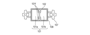
- FIG. 1 is a side view illustrating a schematic structure of a vibration actuator of the present invention using a circular or rectangular piezoelectric material.
- FIG. 1 is a perspective view illustrating a schematic structure of a vibration actuator of the present invention using a circular ring-shaped piezoelectric material or a rectangular piezoelectric material.
- 1 is a rear view illustrating a schematic structure of a vibration actuator of the present invention using a circular ring-shaped piezoelectric material or a rectangular piezoelectric material.
- 1 is a side view illustrating a schematic structure of a vibration actuator of the present invention using a circular ring-shaped piezoelectric material or a rectangular piezoelectric material.
- FIG. 1 is a perspective view illustrating a schematic structure of a vibration actuator of the present invention using a circular ring-shaped piezoelectric material or a rectangular piezoelectric material.
- 1 is a rear view illustrating a schematic structure of a vibration actuator of the present invention using a circular ring-shaped piezoelectric material or a rectangular piezoelectric material.
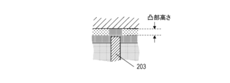
- FIG. 4 is a diagram illustrating a cross-sectional structure around a through-hole of a piezoelectric material before lapping.
- FIG. 13 is a diagram illustrating a cross-sectional structure around a through-hole in a piezoelectric material after an elastic body is bonded (ground electrode thickness ⁇ protrusion amount).
- FIG. 13 is a diagram illustrating a cross-sectional structure around a through-hole of a piezoelectric material after an elastic body is bonded (ground electrode thickness>protrusion amount).
- FIG. 13 is a diagram illustrating a comparative example of a cross-sectional structure around a through hole of a piezoelectric material.
- 4A to 4C are diagrams illustrating the bonding surface of a power supply member, illustrating the general structure of the annular piezoelectric element.
- 1A and 1B are diagrams illustrating an elastic body bonding surface, illustrating a schematic structure of an annular piezoelectric element.
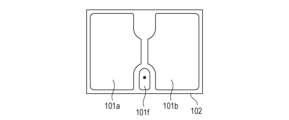
- 4A and 4B are diagrams illustrating the bonding surface of a power supply member, illustrating the general structure of a rectangular piezoelectric element.
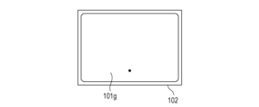
- 4A and 4B are diagrams illustrating an elastic body bonding surface, illustrating a schematic structure of a rectangular piezoelectric element.
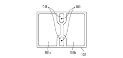
- 4A and 4B are diagrams illustrating the bonding surface of a power supply member, illustrating the general structure of a rectangular piezoelectric element.
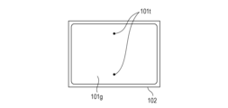
- 4A and 4B are diagrams illustrating an elastic body bonding surface, illustrating a schematic structure of a rectangular piezoelectric element.
- 1A and 1B are diagrams illustrating two vibration modes (mode A) generated by a vibrator of the present invention having a rectangular piezoelectric material.
- 1A and 1B are diagrams illustrating two vibration modes (mode B) generated by a vibrator of the present invention having a rectangular piezoelectric material.
- 1 is a diagram illustrating a schematic structure of an optical device according to the present invention.
- the vibration actuator of the present invention is a vibration actuator that includes a vibrating body having a conductive elastic body and a piezoelectric element provided on the elastic body, and a contact body in contact with the elastic body, and the vibrating body and the contact body move relatively due to vibration of the vibrating body.
- the plate-shaped piezoelectric material that constitutes the piezoelectric element has a through-hole that penetrates the piezoelectric material in the thickness direction and a through-hole electrode filled in the through-hole.
- the through-hole electrode has a protruding portion that protrudes from a first opening of the through-hole, and a ground electrode that is conductive with the through-hole is provided on the surface of the piezoelectric material on the side of the first opening.
- the through-hole electrode and the elastic body are characterized in that they are conductive with each other.
- vibration Actuator 1A to 1F show examples of schematic structures of vibration actuators according to the present invention.
- the vibration actuator 100 of the present invention comprises a vibrator 102 in which an electrode 101, a piezoelectric material 102, and an elastic body 103 are arranged in this order, and a contact body 104 that contacts the elastic body 103.
- the elastic body 103 and the piezoelectric material 102 are joined via an adhesive part 105.
- the elastic body 103 has a protrusion 106, and the protrusion 106 and the contact body 104 are in pressure contact.
- the contact body 104 may be any member that can move relative to the vibrator 110, and is not limited to being in direct contact with the vibrator 110, but may be indirectly in contact with the vibrator 110 via another member.
- the "contact body” refers to a member that comes into contact with the vibrator and moves relative to the vibrator due to vibrations generated in the vibrator.
- the contact between the contact body and the vibrator is not limited to direct contact with no other member between the contact body and the vibrator.
- the contact between the contact body and the vibrator may be indirect contact with another member between the contact body and the vibrator, as long as the contact body moves relative to the vibrator due to vibrations generated in the vibrator.
- the “other member” is not limited to a member independent of the contact body and the vibrator (for example, a high-friction material made of a sintered body).
- the “other member” may be a surface treatment portion formed on the contact body or the vibrator by plating, nitriding, or the like.
- the piezoelectric material 102 constituting the piezoelectric element includes piezoelectric ceramics (sintered body) without crystal orientation, crystal oriented ceramics, and piezoelectric single crystals.
- the thickness of the piezoelectric material is processed to a design value within the range of approximately 0.3 to 0.5 mm.
- the piezoelectric material 102 is provided with at least one through-hole that penetrates in the thickness direction and one through-hole electrode that is filled in the through-hole.
- the through-holes can be arranged symmetrically within the piezoelectric material, or, to reduce the manufacturing costs of the element, a configuration in which only one through-hole is provided for one ground electrode can be adopted.
- the diameter of the through-hole is preferably in the range of 50 to 200 microns.
- Figures 2A to 2D show examples of schematic cross-sectional structures of through-holes provided in a piezoelectric material suitable for the vibration actuator of the present invention.
- a lapping process is applied to the surface of the piezoelectric material provided with the through-hole electrode in order to flatten the surface of the piezoelectric element and adjust the thickness (protrusion amount or height) of the protruding portion of the through-hole electrode.
- a protruding portion of the through-hole electrode is formed in the first opening that opens on the elastic body side of the through-hole.
- the amount of protrusion of the protrusion i.e., the height from the surface of the piezoelectric material to the tip of the through-hole electrode, varies depending on the grit of the media (e.g., silicon carbide) used in the lapping process, and can be adjusted by the grit of the media. For example, the larger the grit of the media, the smaller the amount of protrusion.
- Figure 2A shows the through-hole electrode 203 filled in the through-hole provided in the piezoelectric material 202 protruding from the first opening that opens on the elastic body side of the piezoelectric element, and is lapped so that it protrudes by the thickness sandwiched between the dashed lines.
- Figure 2A shows the state before the lapping process is performed, and the height direction is exaggerated to illustrate the protrusion of the through-hole electrode.
- the through-hole electrode 203 above the upper of the two dashed lines is removed by the lapping process.
- the protrusion amount of the protruding portion 201 of the through-hole electrode 203 sandwiched between the dashed lines is preferably 0.5 microns or more and less than 10 microns. If the protrusion amount is 10 microns or less, the thickness of the adhesive layer can be 10 microns or less, and the vibration efficiency of the vibration actuator can be kept sufficiently good. On the other hand, if the protrusion amount is 10 microns or more, the thickness of the adhesive layer is greater than 10 microns, which may significantly reduce the vibration efficiency of the vibration actuator. Furthermore, the inclination of the elastic body relative to the surface of the piezoelectric material becomes large, which may cause differences in the movement speed of the contact body depending on the direction of travel.
- the protrusion amount it is even more preferable for the protrusion amount to be 5 microns or less. This is because if the protrusion amount is 5 microns or less, the thickness of the adhesive layer will be thinner than 5 microns, and the vibration efficiency of the vibration type actuator can be maintained at a better level.
- the through-hole electrodes In addition to inexpensive silver, silver-palladium, platinum, etc. can be used for the through-hole electrodes.
- the through-hole electrode material When the piezoelectric material and the through-hole electrodes are co-fired, the through-hole electrode material must not melt during the firing process of the piezoelectric material. For this reason, the through-hole electrode material is selected according to the firing temperature of the piezoelectric material, and when the firing temperature exceeds 1300°C, an electrode material whose main component is platinum is used. Main component refers to a weight percent concentration of 90% or more.
- Main component refers to a weight percent concentration of 90% or more.
- the through-hole electrode can also be formed in the through-hole after the piezoelectric material is fired.
- FIG. 2B is an enlarged cross-sectional view showing the state after the through-holes in the piezoelectric material are filled with through-hole electrodes 203, lapping is performed, the ground electrode 204 is formed, and the elastic body 206 and the piezoelectric element are bonded via the adhesive layer 205.
- the ground electrode 204 and through-hole electrode 203 provided after lapping come into contact with the surface of the piezoelectric material on the first opening side, and are electrically connected to each other.
- FIG. 2B shows a case where the thickness of the ground electrode 204 is smaller than the protrusion of the through-hole electrode 203, and the through-hole electrode 203 comes into contact with the elastic body 206, and is electrically connected to each other.
- the through-hole electrode 203 is covered with the ground electrode, and the ground electrode forms a convex portion on the protruding portion.
- the convex portion of the ground electrode may be in contact with the elastic body as shown in FIG. 2C, and the ground electrode may be configured to be conductive with the elastic body.
- the amount of protrusion of the through-hole electrode may also be replaced by the height of the convex portion of the ground electrode. Note that it is possible to confirm that the through-hole electrode is covered with the ground electrode by detecting the constituent elements of the ground electrode between the top of the protruding portion of the through-hole electrode and the elastic body 206.
- the elastic body 103 and the piezoelectric material 102 are bonded via an adhesive layer 205.
- adhesive layer 205 There are no particular limitations on the type of adhesive, but epoxy resin is preferred because it has excellent strength, a short curing time, and is stable even in high temperature and high humidity environments. General epoxy resins are insulating.
- the piezoelectric element does not have the protrusion, increasing the pressure applied when bonding the ground electrode and the elastic body in order to establish electrical conductivity between the ground electrode and the elastic body will significantly thin the adhesive layer and cause parts of the adhesive layer to disappear. As a result, the adhesive strength between the elastic body and the piezoelectric element will decrease, causing peeling during operation of the vibration actuator and resulting in malfunction.
- an adhesive layer is provided between the elastic body and the ground electrode without providing a protrusion on the through-hole electrode, there will be no electrical conductivity between the elastic body and the ground electrode ( Figure 2D). As a result, polarization defects will cause the vibration actuator to malfunction and may also reduce yields.
- a gap is provided between the ground electrode and the elastic body according to the amount of protrusion.
- the gap becomes a space that holds an adhesive material containing an insulating material, and by forming an adhesive layer, the adhesive strength between the piezoelectric element and the elastic body is increased.
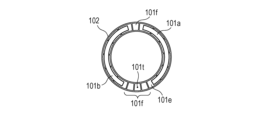
- the piezoelectric material consists of a driving phase electrode 101e and a non-driving phase electrode 101f that are divided in the circumferential direction ( Figure 3A).
- the circumferential length of the driving phase electrode is 1/2 the wavelength ⁇ of the driving frequency.
- the circumferential length of the non-driving phase electrode is 1/4 the wavelength ⁇ of the driving frequency.
- the number of driving phase electrodes and non-driving phase electrodes changes according to the number of traveling waves excited in the circular piezoelectric material.
- the piezoelectric material corresponding to each driving phase electrode is polarized with a voltage of a different polarity from that of adjacent regions.
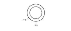
- a circular ground electrode 101g is provided on the surface facing electrodes 101e and 101f (FIG. 3B). At least one of the non-driving phase electrodes provided on the same surface as the driving phase electrode 101e is electrically connected to the ground electrode 101g via a through-hole electrode 101t.
- the shape of the power supply member can be made into a simple, planar structure.
- the driving phase electrodes are separated by an odd number of non-driving phase electrodes.
- An elastic body is bonded to the piezoelectric element, and then a high voltage is applied between the driving phase electrode 101e and the elastic body to polarize the annular piezoelectric material.
- a first electrode 101a and a second electrode 101b are provided to short-circuit the two driving phase electrode groups separated by the non-driving phase electrodes.
- the first electrode 101a and the second electrode 101b are formed at a temperature lower than the depolarization temperature of the piezoelectric material.
- the first electrode 101a and the second electrode 101b are used to drive a vibration type actuator using the annular piezoelectric material.
- FIG. 4A and 4B one through-hole electrode is provided.
- the through-hole electrode is indicated by a black dot in the figure, and the black dot in Figure 4A and the black dot in Figure 4B indicate the top of the through-hole electrode 203 as seen into one opening of the same through-hole and the other opening facing the other.
- the arrangement of through-hole electrodes is not symmetrical with respect to a center line drawn horizontally on the page for the piezoelectric material 102 in the figure for a rectangular piezoelectric element, but it has lower manufacturing costs compared to piezoelectric elements with multiple through-hole electrodes.
- Figures 4C and 4D it is also possible to arrange the through-hole electrodes so that they are substantially symmetrical about the center line in order to improve the vibration quality of the vibration waves generated by the vibrating body.
- Figures 4C and 4D show a rectangular piezoelectric element provided with two through-hole electrodes. By providing two through-hole electrodes, the electrode arrangement becomes symmetrical about the line, and the symmetry of the vibration generated by the piezoelectric element is improved.
- the rectangular piezoelectric material is provided with a first electrode 101a, a second electrode 101b, and a non-driving phase electrode 101f ( Figures 4A and 4C).
- the first electrode 101a and the second electrode 101b are polarized with a voltage of the same polarity and are used to drive a vibration type actuator using the rectangular piezoelectric material.
- a rectangular ground electrode 101g is provided on the surface facing the first electrode 101a and the second electrode 101b. At least one of the non-driving phase electrodes 101f provided on the same surface as the driving phase electrodes 101a and 101b is electrically connected to the ground electrode 101g via a through-hole electrode 101t ( Figures 4B and 4D).
- the surface electrodes formed on the surface of the piezoelectric material i.e., the driving phase electrode, non-driving phase electrode, ground electrode, first electrode, and second electrode excluding the through-hole electrodes, are made of a metal film having a thickness of 0.3 to 10 ⁇ m.
- the material is not particularly limited, but silver, silver-palladium, or gold is generally used. Electrodes mainly composed of inexpensive silver are most preferable. A surface electrode thickness of less than 5 microns is preferable as it suppresses interference with the vibration efficiency of the piezoelectric element.
- the elastic body of the present invention is conductive and is electrically connected to the ground electrode. Therefore, when performing polarization treatment on the piezoelectric material, the elastic body can be used as an electrode.
- a voltage is applied to the driving phase electrode 101e and the non-driving phase electrode 101f that are not electrically connected to the ground electrode 101g, and the elastic body is grounded.
- a voltage is applied to the first electrode 101a and the second electrode 101b, and the elastic body is grounded.
- the elastic body 103 is made of a metal.
- metals that can be used for the elastic body 103 include aluminum, brass, and stainless steel. Among stainless steels, martensitic stainless steel is preferable, and SUS420J2 is most preferable (resistivity at room temperature is 55 ⁇ cm).
- the elastic body has a protrusion 106 that contacts the contact body. When the elastic body is hardened to improve the wear resistance of the protrusion, the hardening process is performed in a vacuum to prevent the formation of an oxide film that increases electrical resistance. SUS420J2 that has been hardened in a vacuum has high hardness and is suitable for the vibration type actuator of the present invention, which drives the contact body by friction with the elastic body.
- the thickness of the elastic body to be bonded to the rectangular piezoelectric material is preferably in the range of 0.2 to 0.35 mm, as this provides both rigidity and springiness and is easy to mold.
- the contact body 104 is preferably made of stainless steel. Among stainless steels, martensitic stainless steel is preferable, and SUS420J2 is most preferable.
- the contact body 104 must have excellent wear resistance because it is in frictional contact with the elastic body 103, and its surface is subjected to a nitriding treatment. A frictional force due to pressurized contact acts between the protrusion 106 and the contact body 104. The vibration generated by the piezoelectric material 102 causes the tip of the protrusion 106 to vibrate elliptically, generating a driving force (thrust) that drives the contact body 104.
- the contact body is generally called a slider or rotor.
- the piezoelectric material in contact with the adjacent driving phase electrodes is polarized with different polarities, so when an electric field of the same polarity is applied to the driving phase electrode 101e, the expansion and contraction polarity in the corresponding region of the piezoelectric material is alternately reversed at a pitch of ⁇ /2.
- a first standing wave with a wavelength ⁇ is generated over the entire circumference of the vibrator.
- a second standing wave is generated in the same manner, but the position of the wave is rotated by ⁇ /4 in the circumferential direction relative to the first standing wave.
- two types of alternating voltages with the same frequency and a temporal phase difference of ⁇ /2 are applied to the first and second electrodes.
- a traveling wave wave number n along the annulus, wavelength ⁇
- bending vibration vibration with amplitude perpendicular to the surface of the vibrator
- each point on the surface of the diaphragm that constitutes the vibrator moves elliptically, and a moving body in contact with this surface rotates due to the circumferential frictional force (driving force) applied from the diaphragm.
- the direction of rotation can be reversed by switching the positive/negative phase difference of the alternating voltage applied to the first electrode and the second electrode.
- the rotation speed can also be controlled by the frequency and amplitude of the alternating voltage applied to the first electrode and the second electrode.
- FIG. 5A and 5B explain two vibration modes generated by the vibrator of the present invention having a rectangular piezoelectric material.
- the regions where the first electrode and the second electrode are provided are the first region and the second region, respectively.
- the structure of the vibration type actuator is as shown in FIG. 1A, FIG. 1E, and FIG. 1F, respectively.
- Mode A When both the first region and the second region expand or contract, a first bending vibration mode (mode A) is generated. Mode A is excited most strongly when the phase difference between the alternating voltages V A and V B applied to the first electrode 101a and the second electrode 101b is 0° and the frequency is near the resonant frequency of mode A. Mode A is a primary out-of-plane vibration mode in which two nodes (where the amplitude is minimum) appear approximately parallel to the long side of the vibrator 110. The protrusion 106 of the elastic body is disposed near the position that is the antinode (where the amplitude is maximum) of mode A. Therefore, the tip surface of the protrusion 106 reciprocates in the Z direction due to vibration mode A.
- Mode B When the first region expands and contracts, the second region contracts and expands, respectively, generating a second bending vibration mode (mode B). Mode B is most strongly excited when the phase difference between the alternating voltages V A and V B applied to the first electrode 101a and the second electrode 101b is 180° and the frequency is near the resonant frequency of mode B. Mode B is a secondary out-of-plane vibration mode in which three nodes appear approximately parallel to the short side of the vibrator 110. The protrusion 106 of the elastic body is disposed near the node position of mode B. Therefore, the tip surface of the protrusion 106 reciprocates in the X direction due to mode B.
- the vibrator is supported by a fitting hole provided in a support part 107 that protrudes from the end of a rectangular part 108.
- the support part 107 can be omitted and the rectangular part 108 of the elastic body can be held.
- the piezoelectric material contains less than 1000 ppm of lead.
- the main component of the piezoelectric material is a barium titanate-based material.
- barium titanate-based materials include barium titanate (BaTiO 3 ), barium calcium titanate ((Ba,Ca)TiO 3 ), barium zirconate titanate (Ba(Ti,Zr)O 3 ), and barium calcium zirconate titanate ((Ba,Ca)(Ti,Zr)O 3 ).
- compositions such as sodium niobate-barium titanate (NaNbO 3 -BaTiO 3 ), sodium bismuth titanate-barium titanate ((Bi 0.5 Na 0.5 )TiO 3 -BaTiO 3 ), and potassium bismuth titanate-barium titanate ((Bi 0.5 K 0.5 )TiO 3 -BaTiO 3 ). It refers to materials that have these compositions as their main components. Among them, the following materials are preferable from the viewpoint of achieving both the piezoelectric constant and mechanical quality factor of the piezoelectric material.
- a main component refers to a material whose weight fraction is greater than 90%.
- the lead content of the piezoelectric material is 1000 ppm or less, it is more preferable because it has a small environmental impact.
- lead zirconate titanate (Pb(Zr,Ti) O3 ) containing lead is widely used in piezoelectric devices.
- the piezoelectric material of the present invention is a barium titanate-based piezoelectric material with a lead content of less than 1000 ppm.
- the lead content can be measured, for example, by ICP atomic emission spectrometry.
- the main component of the piezoelectric material is preferably barium calcium zirconate titanate (hereinafter referred to as BCTZ).
- BCTZ barium calcium zirconate titanate
- the piezoelectricity of BCTZ can be adjusted according to the application by adjusting the amount of Ca and Zr. In addition, the amount of expensive niobium used can be reduced.
- the piezoelectric material is a piezoelectric material containing an oxide of a perovskite structure containing Ba, Ca, Ti, and Zr, and Mn, and the molar ratio x of the Ca to the sum of the Ba and the Ca is 0.02 ⁇ x ⁇ 0.30, the molar ratio y of the Zr to the sum of the Ti and the Zr is 0.020 ⁇ y ⁇ 0.095 and y ⁇ x, the ratio ⁇ of the molar amounts of the Ba and Ca to the molar amounts of the Ti and Zr is 0.9955 ⁇ 1.01, and the content of the Mn relative to 100 parts by weight of the oxide is preferably 0.02 parts by weight or more and 1.0 parts by weight or less in terms of metal.
- Such a piezoelectric material can be represented by the following general formula (1). (Ba1 -xCax ) ⁇ (Ti1 - yZry ) O3 (1) however, 0.986 ⁇ 1.100, 0.02 ⁇ x ⁇ 0.30, 0.02 ⁇ y ⁇ 0.095 and the content of metal components other than the main component contained in the piezoelectric material is preferably 1 part by weight or less in terms of metal per 100 parts by weight of the metal oxide.
- the metal oxide contains Mn, and the content of the Mn is 0.02 parts by weight or more and 0.40 parts by weight or less in terms of metal per 100 parts by weight of the metal oxide.
- Mn is contained within the above range, the insulation properties and the mechanical quality coefficient Qm are improved.
- the mechanical quality coefficient Qm is a coefficient that represents the elastic loss due to vibration when the piezoelectric material is evaluated as a vibrator, and the magnitude of the mechanical quality coefficient is observed as the sharpness of the resonance curve in impedance measurement. In other words, it is a constant that represents the sharpness of the resonance of the vibrator.
- the mechanical quality coefficient Qm is large, the amount of distortion of the piezoelectric material becomes larger near the resonance frequency, and the piezoelectric material can be vibrated effectively.
- the metal oxide represented by the general formula (1) means that the metal elements located at the A site of the perovskite structure are Ba and Ca, and the metal elements located at the B site are Ti and Zr. However, some of the Ba and Ca may be located at the B site. Similarly, some of the Ti and Zr may be located at the A site.
- the molar ratio of the B site element to the O element is 1:3, but even if the molar ratio is slightly different, it is still within the scope of the present invention as long as the metal oxide has a perovskite structure as the main phase.
- a metal oxide has a perovskite structure can be determined, for example, by structural analysis using X-ray diffraction or electron diffraction.
- x which indicates the molar ratio of Ca at the A site, is in the range of 0.02 ⁇ x ⁇ 0.30.
- the phase transition temperature between the orthorhombic and tetragonal crystals shifts to the lower temperature side, so stable piezoelectric vibration can be obtained in the driving temperature range of the vibration actuator.
- x is greater than 0.30, the piezoelectric constant of the piezoelectric material will be insufficient, and the performance of the vibration actuator may be insufficient.
- x is less than 0.02, the dielectric loss (tan ⁇ ) may increase. If the dielectric loss increases, heat generation increases when a voltage is applied to the piezoelectric material to drive the vibration actuator, the motor driving efficiency decreases, and power consumption may increase.
- y which indicates the molar ratio of Zr in the B site, is in the range of 0.02 ⁇ y ⁇ 0.1. If y is greater than 0.1, Td will be low, less than 80°C, and the temperature range in which the vibration actuator can be used will be less than 80°C, which is undesirable.
- Td refers to the lowest temperature at which the piezoelectric constant after heating the piezoelectric material from room temperature to Td one week after polarization processing and then cooling it back to room temperature drops by more than 10% compared to the piezoelectric constant before heating.
- ⁇ which indicates the ratio of the molar amounts of Ba and Ca at the A site to the molar amounts of Ti and Zr at the B site, is preferably in the range of 0.9955 ⁇ 1.010. If ⁇ is smaller than 0.9955, abnormal grain growth is likely to occur in the crystal grains that make up the piezoelectric material, and the mechanical strength of the piezoelectric material decreases. On the other hand, if ⁇ is larger than 1.010, the piezoelectric material does not become highly densified and its insulation becomes extremely brittle.
- the means for measuring the composition of the piezoelectric material there are no particular limitations on the means for measuring the composition of the piezoelectric material. Examples of such means include X-ray fluorescence analysis, ICP atomic emission spectrometry, and atomic absorption spectrometry. Regardless of the measurement means used, the weight ratio and composition ratio of each element contained in the piezoelectric material can be calculated.
- the metal equivalent showing the Mn content is calculated by calculating the content of each metal, Ba, Ca, Ti, Zr and Mn, measured from the piezoelectric material using X-ray fluorescence analysis (XRF), ICP atomic emission spectrometry, atomic absorption spectrometry, etc. From that content, the elements constituting the metal oxide represented by general formula (1) are converted to oxides, and the value is calculated as the ratio of the weight of Mn to the total weight of 100.
- XRF X-ray fluorescence analysis
- ICP atomic emission spectrometry ICP atomic emission spectrometry
- atomic absorption spectrometry atomic absorption spectrometry
- Mn is not limited to metallic Mn, and it is sufficient that it is contained in the piezoelectric material as an Mn component, and the form of its inclusion does not matter. For example, it may be solid-dissolved in the B site, or it may be contained in the grain boundaries. A more preferable form of inclusion is solid-dissolved in the B site from the standpoint of insulation properties and ease of sintering.
- the piezoelectric material contains 0.042 parts by weight or more and 0.850 parts by weight or less of Bi, calculated as metal.
- the piezoelectric material may contain 0.85 parts by weight or less of Bi in terms of metal, relative to 100 parts by weight of the metal oxide represented by the general formula (1).
- the content of Bi relative to the metal oxide can be measured, for example, by ICP emission spectroscopy.
- Bi may be present at the grain boundary of the ceramic piezoelectric material, or may be dissolved in the perovskite structure of (Ba, Ca) (Ti, Zr) O 3.
- Bi When Bi is present at the grain boundary, friction between particles is reduced and the mechanical quality factor is increased.
- Bi when Bi is incorporated into a solid solution that forms a perovskite structure, the phase transition temperature is lowered, so that the temperature dependence of the piezoelectric constant is reduced and the mechanical quality factor is further improved.
- Bi is incorporated into the solid solution, it is preferable that the position of Bi is the A site, since the charge balance with the Mn is improved.
- the piezoelectric material may contain components (hereinafter, subcomponents) other than the elements contained in the general formula (1) and Mn and Bi within a range that does not change the characteristics.
- the total amount of the subcomponents is preferably less than 1.2 parts by weight per 100 parts by weight of the metal oxide expressed by the general formula (1). If the amount of the subcomponents exceeds 1.2 parts by weight, the piezoelectric properties and insulating properties of the piezoelectric material may be deteriorated.
- the Curie temperature of (Ba,Ca)(Ti,Zr) O3 is in the range of 85°C to 126°C.
- the vibration actuator of the present invention has a power supply member joined to a piezoelectric element having the piezoelectric material and the electrodes.
- the power supply member is preferably a flexible printed circuit board (hereinafter FPC) because of its high dimensional accuracy and ease of positioning.
- FPC flexible printed circuit board
- the material is preferably polyimide.
- ACP anisotropic conductive paste
- ACF anisotropic conductive film
- Supplying power through the FPC allows power to be supplied without impeding the vibration of the piezoelectric element.
- the FPC is connected to at least the first electrode and the second electrode, and may also be connected to the non-driving phase electrode.
- the method for manufacturing piezoelectric elements is as follows. First, the raw powder of piezoelectric material is molded using a sheet molding method to create a green sheet with a thickness of 30 to 200 microns. Next, the positions for forming the through holes are determined taking into consideration factors such as shrinkage during firing and cutting margins during dicing, and the green sheet is punched with a punch with a diameter of, for example, 150 microns to form the through holes.
- the through-hole electrode paste into the through-hole.
- a heat-resistant material that will not melt during the firing process is selected for the through-hole electrode material.
- the aforementioned (Ba,Ca)(Ti,Zr)O 3 requires a firing temperature of at least 1300°C, so a material containing platinum as the main component is used for the through-hole electrode.
- the aforementioned NaNbO 3 -BaTiO 3 requires a firing temperature of 1200 to 1260°C, so Ag-Pd (e.g. 0.5Ag-0.5Pd) is used for the through-hole electrode.
- the required number of green sheets are stacked and compressed, taking into consideration shrinkage during firing and the margin for scraping during the lapping process.
- the through-holes are aligned in the stacking direction so that the through-hole electrodes do not break.
- the laminated and pressed molded body is fired, and then a lapping process is performed to adjust the thickness of the piezoelectric material.
- the amount of protrusion of the through-hole electrode changes depending on the lapping conditions at this time.
- the amount of protrusion varies depending on the lapping conditions such as the grit (grain size) of the abrasive, the work load, and the rotation speed of the platen, but is most dependent on the grit. The lower the grit, the greater the amount of protrusion.
- the surface electrodes are printed and baked.
- the piezoelectric material with the surface electrodes is then diced to separate into individual element pieces.
- the dimensions of the rectangular piezoelectric element of the present invention are 9 mm x 6 mm, and the thickness is 0.3 to 0.45 mm.
- the manufacturing method of the vibrator constituting the vibration type actuator of the present invention is as follows. First, a step of bonding a piezoelectric element and an elastic body with an adhesive at temperature T1, and a step of bonding the piezoelectric element and a power supply member at temperature T2 are carried out. Then, a step of applying a voltage between the electrode and the elastic body and carrying out a polarization process at temperature T3 are carried out in this order to manufacture the vibrator.
- the T1, T2, and T3 satisfy the relationships T1>T3 and T2>T3.
- the electronic device of the present invention is characterized by comprising the above-mentioned vibration actuator, a member connected to the contact body of the vibration actuator, and a member position detection means (e.g., an encoder).
- the electronic device detects the position of the member and operates the vibration actuator until the member reaches a target position, thereby enabling precise control of the position of the member.
- the optical apparatus of the present invention includes the vibration actuator described above in a drive section, and further includes at least one of an optical element and an imaging element.
- FIG. 5A and 5B are schematic diagrams showing an embodiment of the optical device (focus lens part of the lens barrel device) of the present invention.
- the vibrator 110 having a rectangular piezoelectric material is in pressure contact with the contact body (slider) 104 as in FIG. 1D.
- the power supply member 507 is connected to the surface side having the first and second regions.
- a voltage input means not shown
- an elliptical motion is generated in the protrusion of the elastic body (not shown).
- the holding member 501 is joined to the vibrator 110 and is configured not to generate unnecessary vibrations.
- the moving housing 502 is fixed to the holding member 501 with a screw 503 and is integrated with the vibrator 110. These members form the electronic device of the present invention. By attaching the moving housing 502 to the guide member 504, the electronic device of the present invention can move linearly in both directions (forward and reverse) along the guide member 504.
- the lens 506 (optical member) that serves as the focus lens of the telescope barrel device.
- the lens 506 is fixed to the lens holding member 505, and has an optical axis (not shown) parallel to the movement direction of the vibration actuator.
- the lens holding member 505 moves linearly on two guide members 504 (described below) to perform focal position adjustment (focus operation).
- the two guide members 504 are members that engage the movable housing 502 and the lens holding member 505, enabling the movable housing 502 and the lens holding member 505 to move linearly. With this configuration, the movable housing 502 and the lens holding member 505 can move linearly on the guide members 504.
- the connecting member 510 is a member that transmits the driving force generated by the vibration actuator to the lens holding member 505, and is fitted and attached to the lens holding member 505. This allows the lens holding member 505 to move smoothly in both directions along the two guide members 504 together with the movable housing 502.
- the sensor 508 is provided to detect the position of the lens holding member 505 on the guide member 504 by reading the position information of a scale 509 attached to the side of the lens holding member 505.
- the focus lens section of the telescope barrel device is constructed by incorporating each of the above-mentioned components.
- a lens barrel device for a single-lens reflex camera has been described as an example of an optical device, but the device can be applied to a variety of optical devices equipped with a vibration actuator, regardless of the type of camera, such as a compact camera in which the lens and camera body are integrated, or an electronic still camera.
- Another configuration of the vibration actuator may be one in which multiple vibrators are in contact with a common contact body, and the contact body moves relative to the multiple vibrators as the multiple vibrators vibrate.
- vibration actuator of the present invention applications in the medical or engineering fields are conceivable. Specifically, it is possible to configure a wire-driven actuator that has an elongated member, a wire that is inserted through the elongated member and fixed to a part of the elongated member, and the above-mentioned vibration actuator that drives the wire, and in which the elongated member is curved by driving the wire.
- a piezoelectric element with a protruding through-hole electrode was fabricated according to the manufacturing method for the piezoelectric element described above.
- the relationship between the size of the media used to lap the piezoelectric material and the protruding amount of the through-hole electrode is shown in Table 1.
- Example 1 A circular ring-shaped compact of (Ba,Ca)(Ti,Zr) O3 with a through-hole electrode was sintered at 1340°C.
- the thickness of the piezoelectric material of the obtained sintered body was adjusted to 0.5 mm using silicon carbide powder of No. 4000.
- the protrusion amount of the through-hole electrode was 1 to 3 microns.
- the inner and outer diameters were also ground to process it into a circular ring with an outer diameter of 62 mm and an inner diameter of 54 mm.
- the driving phase electrode 101e and non-driving phase electrode 101f shown in Figure 3A were formed on one side of the shaped piezoelectric material 102.
- the driving phase electrode 101e and the non-driving phase electrode 101f are printed so that the middle non-driving phase electrode and the through-hole are joined.
- the ground electrode 101g in Figure 3B is conductive with one of the non-driving phase electrodes 101f via the through-hole electrode 101t.
- the surface electrodes formed by the screen printing method are dried and then baked at 600 to 850°C. The thickness of the silver surface electrode after baking was 6 microns.
- the FPC coated with ACP was thermocompressed to the electrodes on the piezoelectric material.
- the elastic body SUS420J2 was grounded, and voltages of different polarities were alternately applied to adjacent driving phase electrodes 101e to perform polarization processing.
- the polarization processing multiple external electrodes connected to a power source were brought into contact with the driving phase electrode 101e and the electrode of the driven phase electrode 101f that is not conductive with the installation electrode 101t and is used as a sensor.
- the first electrode 101a and the second electrode 101b were printed and dried to obtain a vibrator.
- the temperature of the piezoelectric material was kept below 80°C to prevent depolarization of the piezoelectric material.
- the obtained vibrator was pressed into contact with a contact body (rotor) made of SUS420J2 to create a vibration actuator.
- Example 2 A plate-shaped molded body of (Ba,Ca)(Ti,Zr) O3 provided with a through-hole electrode was sintered at 1340°C.
- the composition of the through-hole electrode was platinum.
- the thickness of the piezoelectric material of the obtained sintered body was adjusted to 0.4 mm using 4000-number silicon carbide powder.
- the protrusion amount of the through-hole electrode was 1 to 3 microns.
- the first electrode 101a, the second electrode 101b, and the non-driving phase electrode 101f shown in FIG. 4A were printed and dried.
- the installation electrode 101g was printed and dried on the opposite side of the piezoelectric material.
- the surface electrode was baked at 600 to 850°C.
- the thickness of the silver surface electrode after baking was 3 microns.
- the ground electrode 101g was conductive with the non-driving phase electrode 101t via the through-hole electrode 101t. Thereafter, the piezoelectric material having the surface electrodes formed thereon was cut into individual pieces of 8.9 mm ⁇ 5.7 mm using a dicing device, to obtain the rectangular piezoelectric elements shown in FIG. 4A.
- an epoxy-based thermosetting adhesive was applied to the elastic body 103 shown in Figure 1E, which was made of SUS420J2, and it was pressed against the piezoelectric material 102 on which the electrodes were formed.
- a heat treatment was carried out to harden the adhesive.
- the FPC coated with ACP was thermocompressed to the non-driving phase electrode provided on the piezoelectric material to produce a vibrator.
- the elastic body SUS420J2 was grounded, and a voltage of the same polarity was applied to the first electrode 101a and the second electrode 101b to perform polarization processing.
- the polarization processing two external electrodes connected to a power source were brought into contact with the first electrode 101a and the second electrode 101b.
- the obtained vibrator was pressurized and brought into contact with a contact body (rotor) made of SUS420J2 to produce a vibration type actuator.
- Example 3 A vibration type actuator was produced in the same manner as in Example 2, except that #2000 silicon carbide powder was used to wrap the sintered body.
- the protrusion amount of the through-hole electrode was 3 to 5 microns.
- Example 4 A vibration type actuator was produced in the same manner as in Example 2, except that #1000 silicon carbide powder was used to wrap the sintered body.
- the protrusion amount of the through-hole electrode was 5 to 10 microns.
- Example 5 A plate-shaped molded body of 0.88NaNbO 3 -0.12BaTiO 3 provided with a through-hole electrode was sintered at 1260°C.
- the composition of the through-hole electrode was 5Ag-5Pd, a mixture of silver and palladium in a molar ratio of 1:1.
- the thickness of the piezoelectric material of the obtained sintered body was adjusted to 0.35 mm using silicon carbide powder of No. 4000. At this time, the protrusion amount of the through-hole electrode was 1 to 3 microns.
- the installation electrode 101g was printed on the opposite side of the piezoelectric material and dried.
- the surface electrode was baked at 600 to 850°C.
- the ground electrode 101g was conductive to the non-driving phase electrode 101t via the through-hole electrode 101t.
- the piezoelectric material having the surface electrodes formed thereon was cut into individual pieces of 8.5 mm ⁇ 5.7 mm using a dicing device, to obtain the rectangular piezoelectric elements shown in FIG. 4C.
- thermosetting adhesive was applied to the elastic body 103 shown in Fig. 1E, which was made of SUS420J2, and the elastic body was pressed against the piezoelectric material 102 of 0.88NaNbO3-0.12BaTiO3 on which electrodes were formed.
- a heat treatment was carried out to harden the adhesive.
- the FPC coated with ACP was thermocompressed to the non-driving phase electrode provided on the piezoelectric material to produce a vibrator.
- the elastic body SUS420J2 was grounded, and a voltage of the same polarity was applied to the first electrode 101a and the second electrode 101b to perform polarization processing.
- the polarization processing two external electrodes connected to a power source were brought into contact with the first electrode 101a and the second electrode 101b.
- the contact body When the frequency of the alternating voltage is swept from a frequency higher than the resonant frequency of vibration mode A and vibration mode B toward the resonant frequency, the contact body is driven in a direction according to the phase difference of the alternating voltage and stops after reaching maximum speed.
- the directions of travel when the phase difference is -90° and 90° are called the reverse direction and forward direction, respectively.
- the maximum speed of the vibrator and the frequency at which the maximum speed was reached were measured with a sensor.
- the power (rated power) at a rated speed lower than the maximum speed was calculated from the current flowing through the drive circuit.
- the rated power of the vibration actuators of Examples 2 and 3 was approximately 10% lower than that of the vibration actuator of Example 4, and was generally the same.
- the drive characteristics of the vibration actuators of Examples 2 to 4 were evaluated for durability by performing continuous reciprocating motion, and no significant deterioration in the drive characteristics was observed even after the test.
- (Comparative Example 1) A green sheet of (Ba,Ca)(Ti,Zr) O3 with a thickness of about 130 microns was prepared. After forming through holes in the green sheet with a punch, the green sheets were laminated, pressed, and sintered at 1340°C without printing through-hole electrodes. The obtained sintered body was adjusted to a thickness of 0.4 mm using silicon carbide powder of No. 4000. The first electrode 101a, the second electrode 101b, and the non-driving phase electrode 101f shown in FIG. 4A were printed and dried on one side of the plate-shaped piezoelectric material 102 with the adjusted thickness. Next, the installation electrode 101g was printed and dried on the opposite side of the piezoelectric material.
- the electrodes are filled in the through-holes through the printing process of these surface electrodes.
- the surface electrode and the through-hole electrode were baked at 600 to 850°C.
- the protrusion amount of the through-hole electrode was 0 microns or less.
- the ground electrode 101g was conductive with the non-driving phase electrode 101t via the through-hole electrode 101t.
- the piezoelectric material having the surface electrodes formed thereon was cut into individual pieces of 8.9 mm ⁇ 5.7 mm using a dicing device, to obtain the rectangular piezoelectric elements shown in FIG. 4A.
- an epoxy-based thermosetting adhesive was applied to the elastic body 103 shown in Figure 1E, which was made of SUS420J2, and it was pressed against the piezoelectric material 102 on which the electrodes were formed.
- a heat treatment was carried out to harden the adhesive.
- Example 6 The vibration actuator produced in Example 2 was mechanically connected to an optical member to produce the optical device shown in Fig. 6.
- an optical lens was connected to the vibration actuator, and it was confirmed that it had an autofocus function.
- the elastic body and the ground electrode are electrically connected. Therefore, no polarization defects occur in the process of grounding the elastic body and performing a polarization process on the piezoelectric material, and vibration actuators can be manufactured with a good yield.
- the vibration actuator of the present invention can be used for a variety of purposes, such as driving lenses and image pickup elements in imaging devices (optical equipment), driving the rotation of photosensitive drums in copiers, and driving stages. Although a single vibration actuator has been described in this specification, it is also possible to arrange multiple vibration actuators in a circular ring shape to drive the rotation of a ring-shaped contact body.
Landscapes
- Engineering & Computer Science (AREA)
- Physics & Mathematics (AREA)
- Chemical & Material Sciences (AREA)
- General Physics & Mathematics (AREA)
- Optics & Photonics (AREA)
- Ceramic Engineering (AREA)
- Mechanical Engineering (AREA)
- Composite Materials (AREA)
- Materials Engineering (AREA)
- General Electrical Machinery Utilizing Piezoelectricity, Electrostriction Or Magnetostriction (AREA)
- Lens Barrels (AREA)
Priority Applications (3)
| Application Number | Priority Date | Filing Date | Title |
|---|---|---|---|
| CN202380074958.2A CN120130022A (zh) | 2022-10-24 | 2023-10-06 | 振动型致动器、光学设备和电子设备 |
| EP23882380.1A EP4611248A1 (en) | 2022-10-24 | 2023-10-06 | Vibration actuator, optical device, and electronic device |
| US19/187,637 US20250255189A1 (en) | 2022-10-24 | 2025-04-23 | Vibration-type actuator, optical device, and electronic device |
Applications Claiming Priority (2)
| Application Number | Priority Date | Filing Date | Title |
|---|---|---|---|
| JP2022170049A JP2024062199A (ja) | 2022-10-24 | 2022-10-24 | 振動型アクチュエータ、光学機器および電子機器 |
| JP2022-170049 | 2022-10-24 |
Related Child Applications (1)
| Application Number | Title | Priority Date | Filing Date |
|---|---|---|---|
| US19/187,637 Continuation US20250255189A1 (en) | 2022-10-24 | 2025-04-23 | Vibration-type actuator, optical device, and electronic device |
Publications (1)
| Publication Number | Publication Date |
|---|---|
| WO2024090171A1 true WO2024090171A1 (ja) | 2024-05-02 |
Family
ID=90830517
Family Applications (1)
| Application Number | Title | Priority Date | Filing Date |
|---|---|---|---|
| PCT/JP2023/036462 Ceased WO2024090171A1 (ja) | 2022-10-24 | 2023-10-06 | 振動型アクチュエータ、光学機器および電子機器 |
Country Status (5)
| Country | Link |
|---|---|
| US (1) | US20250255189A1 (OSRAM) |
| EP (1) | EP4611248A1 (OSRAM) |
| JP (1) | JP2024062199A (OSRAM) |
| CN (1) | CN120130022A (OSRAM) |
| WO (1) | WO2024090171A1 (OSRAM) |
Families Citing this family (1)
| Publication number | Priority date | Publication date | Assignee | Title |
|---|---|---|---|---|
| CN121001958A (zh) | 2023-04-25 | 2025-11-21 | 佳能株式会社 | 单线态氧的产生方法、单线态氧的产生系统、单线态氧的产生试剂盒和单线态氧产生剂 |
Citations (5)
| Publication number | Priority date | Publication date | Assignee | Title |
|---|---|---|---|---|
| JP2017005794A (ja) * | 2015-06-05 | 2017-01-05 | キヤノン株式会社 | 振動型駆動装置 |
| JP2017005795A (ja) * | 2015-06-05 | 2017-01-05 | キヤノン株式会社 | 振動型駆動装置及び医用システム |
| JP2017184233A (ja) | 2016-03-25 | 2017-10-05 | キヤノン株式会社 | 振動子の製造方法、振動波駆動装置の製造方法および光学機器の製造方法 |
| JP2022008140A (ja) * | 2020-06-26 | 2022-01-13 | キヤノン株式会社 | 振動型アクチュエータ、光学機器および電子機器 |
| JP2022170049A (ja) | 2021-04-28 | 2022-11-10 | 裕宜 橋爪 | 試料採取用濾過装置 |
-
2022
- 2022-10-24 JP JP2022170049A patent/JP2024062199A/ja active Pending
-
2023
- 2023-10-06 CN CN202380074958.2A patent/CN120130022A/zh active Pending
- 2023-10-06 WO PCT/JP2023/036462 patent/WO2024090171A1/ja not_active Ceased
- 2023-10-06 EP EP23882380.1A patent/EP4611248A1/en active Pending
-
2025
- 2025-04-23 US US19/187,637 patent/US20250255189A1/en active Pending
Patent Citations (5)
| Publication number | Priority date | Publication date | Assignee | Title |
|---|---|---|---|---|
| JP2017005794A (ja) * | 2015-06-05 | 2017-01-05 | キヤノン株式会社 | 振動型駆動装置 |
| JP2017005795A (ja) * | 2015-06-05 | 2017-01-05 | キヤノン株式会社 | 振動型駆動装置及び医用システム |
| JP2017184233A (ja) | 2016-03-25 | 2017-10-05 | キヤノン株式会社 | 振動子の製造方法、振動波駆動装置の製造方法および光学機器の製造方法 |
| JP2022008140A (ja) * | 2020-06-26 | 2022-01-13 | キヤノン株式会社 | 振動型アクチュエータ、光学機器および電子機器 |
| JP2022170049A (ja) | 2021-04-28 | 2022-11-10 | 裕宜 橋爪 | 試料採取用濾過装置 |
Also Published As
| Publication number | Publication date |
|---|---|
| US20250255189A1 (en) | 2025-08-07 |
| EP4611248A1 (en) | 2025-09-03 |
| CN120130022A (zh) | 2025-06-10 |
| JP2024062199A (ja) | 2024-05-09 |
Similar Documents
| Publication | Publication Date | Title |
|---|---|---|
| JP7302059B2 (ja) | 振動子、振動波駆動装置、振動波モータおよび電子機器 | |
| US10593864B2 (en) | Piezoelectric element oscillatory wave motor and optical apparatus | |
| US10536097B2 (en) | Ultrasonic motor, drive control system, optical apparatus, and vibrator | |
| JP6901886B2 (ja) | 振動子の製造方法、振動波駆動装置の製造方法および光学機器の製造方法 | |
| KR20160019968A (ko) | 진동파 구동 디바이스, 진동파 모터용 스테이터, 진동파 모터, 구동 제어 시스템, 광학 장치, 및 진동파 구동 디바이스의 제조 방법 | |
| US20240049606A1 (en) | Vibration actuator, optical device, and electronic device | |
| US20250255189A1 (en) | Vibration-type actuator, optical device, and electronic device | |
| US10451833B2 (en) | Ultrasonic motor, drive control system, optical apparatus, and vibrator | |
| JP7254631B2 (ja) | 振動波モータ、駆動制御システムおよび光学機器 | |
| US20240030835A1 (en) | Vibration actuator, electronic apparatus, and optical apparatus | |
| US20230378890A1 (en) | Vibration-type actuator, electronic device, and optical device | |
| US20250343489A1 (en) | Vibration-type actuator, manufacturing method of vibration-type actuator, electronic device, and optical device | |
| JP2025169885A (ja) | 振動型アクチュエータ、振動型アクチュエータの製造方法、電子機器、および光学機器 | |
| JP7000036B2 (ja) | 振動子、振動子の製造方法、および電子機器 | |
| WO2024257696A1 (ja) | 振動型アクチュエータ、電子機器、光学機器、及び、振動型アクチュエータの製造方法 |
Legal Events
| Date | Code | Title | Description |
|---|---|---|---|
| 121 | Ep: the epo has been informed by wipo that ep was designated in this application |
Ref document number: 23882380 Country of ref document: EP Kind code of ref document: A1 |
|
| WWE | Wipo information: entry into national phase |
Ref document number: 202380074958.2 Country of ref document: CN |
|
| WWE | Wipo information: entry into national phase |
Ref document number: 2023882380 Country of ref document: EP |
|
| NENP | Non-entry into the national phase |
Ref country code: DE |
|
| ENP | Entry into the national phase |
Ref document number: 2023882380 Country of ref document: EP Effective date: 20250526 |
|
| WWP | Wipo information: published in national office |
Ref document number: 202380074958.2 Country of ref document: CN |
|
| WWP | Wipo information: published in national office |
Ref document number: 2023882380 Country of ref document: EP |