WO2024090171A1 - Vibration actuator, optical device, and electronic device - Google Patents
Vibration actuator, optical device, and electronic device Download PDFInfo
- Publication number
- WO2024090171A1 WO2024090171A1 PCT/JP2023/036462 JP2023036462W WO2024090171A1 WO 2024090171 A1 WO2024090171 A1 WO 2024090171A1 JP 2023036462 W JP2023036462 W JP 2023036462W WO 2024090171 A1 WO2024090171 A1 WO 2024090171A1
- Authority
- WO
- WIPO (PCT)
- Prior art keywords
- electrode
- piezoelectric material
- vibration actuator
- hole
- elastic body
- Prior art date
Links
- 230000003287 optical effect Effects 0.000 title claims description 18
- 239000000463 material Substances 0.000 claims abstract description 166
- 239000000853 adhesive Substances 0.000 claims description 22
- 230000001070 adhesive effect Effects 0.000 claims description 22
- 229910002113 barium titanate Inorganic materials 0.000 claims description 10
- BASFCYQUMIYNBI-UHFFFAOYSA-N platinum Chemical compound [Pt] BASFCYQUMIYNBI-UHFFFAOYSA-N 0.000 claims description 10
- 238000005452 bending Methods 0.000 claims description 7
- 229910052709 silver Inorganic materials 0.000 claims description 7
- 239000004332 silver Substances 0.000 claims description 7
- JRPBQTZRNDNNOP-UHFFFAOYSA-N barium titanate Chemical compound [Ba+2].[Ba+2].[O-][Ti]([O-])([O-])[O-] JRPBQTZRNDNNOP-UHFFFAOYSA-N 0.000 claims description 6
- RTAQQCXQSZGOHL-UHFFFAOYSA-N Titanium Chemical compound [Ti] RTAQQCXQSZGOHL-UHFFFAOYSA-N 0.000 claims description 5
- 229910052697 platinum Inorganic materials 0.000 claims description 5
- FQNGWRSKYZLJDK-UHFFFAOYSA-N [Ca].[Ba] Chemical compound [Ca].[Ba] FQNGWRSKYZLJDK-UHFFFAOYSA-N 0.000 claims description 4
- 238000003384 imaging method Methods 0.000 claims description 3
- 229910001105 martensitic stainless steel Inorganic materials 0.000 claims description 3
- 239000011810 insulating material Substances 0.000 claims description 2
- 230000000149 penetrating effect Effects 0.000 claims description 2
- 238000000034 method Methods 0.000 description 24
- 239000011575 calcium Substances 0.000 description 20
- 230000010287 polarization Effects 0.000 description 18
- 229910052791 calcium Inorganic materials 0.000 description 16
- 239000011572 manganese Substances 0.000 description 16
- 229910052726 zirconium Inorganic materials 0.000 description 16
- 238000010586 diagram Methods 0.000 description 14
- 229910052751 metal Inorganic materials 0.000 description 13
- 239000012790 adhesive layer Substances 0.000 description 12
- 238000004519 manufacturing process Methods 0.000 description 12
- 239000002184 metal Substances 0.000 description 11
- 229910044991 metal oxide Inorganic materials 0.000 description 10
- 150000004706 metal oxides Chemical class 0.000 description 10
- 238000010304 firing Methods 0.000 description 8
- 239000000203 mixture Substances 0.000 description 8
- 238000012545 processing Methods 0.000 description 8
- 229910052788 barium Inorganic materials 0.000 description 7
- 230000005684 electric field Effects 0.000 description 7
- HBMJWWWQQXIZIP-UHFFFAOYSA-N silicon carbide Chemical compound [Si+]#[C-] HBMJWWWQQXIZIP-UHFFFAOYSA-N 0.000 description 7
- 229910052719 titanium Inorganic materials 0.000 description 7
- BQCADISMDOOEFD-UHFFFAOYSA-N Silver Chemical compound [Ag] BQCADISMDOOEFD-UHFFFAOYSA-N 0.000 description 6
- 239000013078 crystal Substances 0.000 description 6
- 238000010438 heat treatment Methods 0.000 description 6
- 239000000919 ceramic Substances 0.000 description 4
- 239000007772 electrode material Substances 0.000 description 4
- 238000009434 installation Methods 0.000 description 4
- 230000033001 locomotion Effects 0.000 description 4
- 229910052748 manganese Inorganic materials 0.000 description 4
- 229910001220 stainless steel Inorganic materials 0.000 description 4
- 239000004593 Epoxy Substances 0.000 description 3
- 238000001636 atomic emission spectroscopy Methods 0.000 description 3
- 230000007423 decrease Effects 0.000 description 3
- 238000009413 insulation Methods 0.000 description 3
- 230000028161 membrane depolarization Effects 0.000 description 3
- KDLHZDBZIXYQEI-UHFFFAOYSA-N palladium Substances [Pd] KDLHZDBZIXYQEI-UHFFFAOYSA-N 0.000 description 3
- 239000011734 sodium Substances 0.000 description 3
- 229920001187 thermosetting polymer Polymers 0.000 description 3
- DGAQECJNVWCQMB-PUAWFVPOSA-M Ilexoside XXIX Chemical compound C[C@@H]1CC[C@@]2(CC[C@@]3(C(=CC[C@H]4[C@]3(CC[C@@H]5[C@@]4(CC[C@@H](C5(C)C)OS(=O)(=O)[O-])C)C)[C@@H]2[C@]1(C)O)C)C(=O)O[C@H]6[C@@H]([C@H]([C@@H]([C@H](O6)CO)O)O)O.[Na+] DGAQECJNVWCQMB-PUAWFVPOSA-M 0.000 description 2
- 238000004458 analytical method Methods 0.000 description 2
- 238000001479 atomic absorption spectroscopy Methods 0.000 description 2
- 230000015572 biosynthetic process Effects 0.000 description 2
- 229910052797 bismuth Inorganic materials 0.000 description 2
- 230000000052 comparative effect Effects 0.000 description 2
- 230000007547 defect Effects 0.000 description 2
- 239000003822 epoxy resin Substances 0.000 description 2
- 230000007257 malfunction Effects 0.000 description 2
- 238000005121 nitriding Methods 0.000 description 2
- SWELZOZIOHGSPA-UHFFFAOYSA-N palladium silver Chemical compound [Pd].[Ag] SWELZOZIOHGSPA-UHFFFAOYSA-N 0.000 description 2
- 229920000647 polyepoxide Polymers 0.000 description 2
- 238000007639 printing Methods 0.000 description 2
- 229910052708 sodium Inorganic materials 0.000 description 2
- 239000006104 solid solution Substances 0.000 description 2
- 239000010935 stainless steel Substances 0.000 description 2
- 238000012360 testing method Methods 0.000 description 2
- 230000007704 transition Effects 0.000 description 2
- 238000004876 x-ray fluorescence Methods 0.000 description 2
- 229910001369 Brass Inorganic materials 0.000 description 1
- PWHULOQIROXLJO-UHFFFAOYSA-N Manganese Chemical compound [Mn] PWHULOQIROXLJO-UHFFFAOYSA-N 0.000 description 1
- 229910020276 Pb(Zr,Ti) O3 Inorganic materials 0.000 description 1
- 239000004642 Polyimide Substances 0.000 description 1
- 238000002441 X-ray diffraction Methods 0.000 description 1
- YPQJHZKJHIBJAP-UHFFFAOYSA-N [K].[Bi] Chemical compound [K].[Bi] YPQJHZKJHIBJAP-UHFFFAOYSA-N 0.000 description 1
- 230000002159 abnormal effect Effects 0.000 description 1
- 238000003916 acid precipitation Methods 0.000 description 1
- 229910052782 aluminium Inorganic materials 0.000 description 1
- XAGFODPZIPBFFR-UHFFFAOYSA-N aluminium Chemical compound [Al] XAGFODPZIPBFFR-UHFFFAOYSA-N 0.000 description 1
- 229910021523 barium zirconate Inorganic materials 0.000 description 1
- DQBAOWPVHRWLJC-UHFFFAOYSA-N barium(2+);dioxido(oxo)zirconium Chemical compound [Ba+2].[O-][Zr]([O-])=O DQBAOWPVHRWLJC-UHFFFAOYSA-N 0.000 description 1
- JCXGWMGPZLAOME-UHFFFAOYSA-N bismuth atom Chemical compound [Bi] JCXGWMGPZLAOME-UHFFFAOYSA-N 0.000 description 1
- FSAJRXGMUISOIW-UHFFFAOYSA-N bismuth sodium Chemical compound [Na].[Bi] FSAJRXGMUISOIW-UHFFFAOYSA-N 0.000 description 1
- 239000010951 brass Substances 0.000 description 1
- JXDXDSKXFRTAPA-UHFFFAOYSA-N calcium;barium(2+);oxygen(2-);titanium(4+) Chemical compound [O-2].[Ca+2].[Ti+4].[Ba+2] JXDXDSKXFRTAPA-UHFFFAOYSA-N 0.000 description 1
- 238000006243 chemical reaction Methods 0.000 description 1
- 239000000470 constituent Substances 0.000 description 1
- 230000008602 contraction Effects 0.000 description 1
- 238000001816 cooling Methods 0.000 description 1
- RKTYLMNFRDHKIL-UHFFFAOYSA-N copper;5,10,15,20-tetraphenylporphyrin-22,24-diide Chemical compound [Cu+2].C1=CC(C(=C2C=CC([N-]2)=C(C=2C=CC=CC=2)C=2C=CC(N=2)=C(C=2C=CC=CC=2)C2=CC=C3[N-]2)C=2C=CC=CC=2)=NC1=C3C1=CC=CC=C1 RKTYLMNFRDHKIL-UHFFFAOYSA-N 0.000 description 1
- 238000005520 cutting process Methods 0.000 description 1
- 230000001419 dependent effect Effects 0.000 description 1
- 238000013461 design Methods 0.000 description 1
- 238000001514 detection method Methods 0.000 description 1
- 230000006866 deterioration Effects 0.000 description 1
- 238000001035 drying Methods 0.000 description 1
- 230000000694 effects Effects 0.000 description 1
- 239000002003 electrode paste Substances 0.000 description 1
- 238000002003 electron diffraction Methods 0.000 description 1
- 238000004993 emission spectroscopy Methods 0.000 description 1
- 230000007613 environmental effect Effects 0.000 description 1
- 238000011156 evaluation Methods 0.000 description 1
- 239000002783 friction material Substances 0.000 description 1
- PCHJSUWPFVWCPO-UHFFFAOYSA-N gold Chemical compound [Au] PCHJSUWPFVWCPO-UHFFFAOYSA-N 0.000 description 1
- 229910052737 gold Inorganic materials 0.000 description 1
- 239000010931 gold Substances 0.000 description 1
- LNEPOXFFQSENCJ-UHFFFAOYSA-N haloperidol Chemical compound C1CC(O)(C=2C=CC(Cl)=CC=2)CCN1CCCC(=O)C1=CC=C(F)C=C1 LNEPOXFFQSENCJ-UHFFFAOYSA-N 0.000 description 1
- 230000020169 heat generation Effects 0.000 description 1
- 239000003779 heat-resistant material Substances 0.000 description 1
- 238000002847 impedance measurement Methods 0.000 description 1
- 238000005304 joining Methods 0.000 description 1
- 229910052451 lead zirconate titanate Inorganic materials 0.000 description 1
- HFGPZNIAWCZYJU-UHFFFAOYSA-N lead zirconate titanate Chemical compound [O-2].[O-2].[O-2].[O-2].[O-2].[Ti+4].[Zr+4].[Pb+2] HFGPZNIAWCZYJU-UHFFFAOYSA-N 0.000 description 1
- 238000005259 measurement Methods 0.000 description 1
- 150000002739 metals Chemical class 0.000 description 1
- 238000012986 modification Methods 0.000 description 1
- 230000004048 modification Effects 0.000 description 1
- 238000000465 moulding Methods 0.000 description 1
- 229910052758 niobium Inorganic materials 0.000 description 1
- 239000010955 niobium Substances 0.000 description 1
- GUCVJGMIXFAOAE-UHFFFAOYSA-N niobium atom Chemical compound [Nb] GUCVJGMIXFAOAE-UHFFFAOYSA-N 0.000 description 1
- 229910052763 palladium Inorganic materials 0.000 description 1
- 239000002245 particle Substances 0.000 description 1
- 238000007747 plating Methods 0.000 description 1
- 229920001721 polyimide Polymers 0.000 description 1
- 239000000843 powder Substances 0.000 description 1
- 238000003825 pressing Methods 0.000 description 1
- 230000011514 reflex Effects 0.000 description 1
- 238000007790 scraping Methods 0.000 description 1
- 238000007650 screen-printing Methods 0.000 description 1
- 229910010271 silicon carbide Inorganic materials 0.000 description 1
- 238000005245 sintering Methods 0.000 description 1
- 239000002689 soil Substances 0.000 description 1
- 238000012916 structural analysis Methods 0.000 description 1
- 238000004381 surface treatment Methods 0.000 description 1
- 238000003786 synthesis reaction Methods 0.000 description 1
- 230000002123 temporal effect Effects 0.000 description 1
Images


Definitions
- the present invention relates to a vibration actuator including an ultrasonic motor.
- a vibration actuator has a vibrator configured so that vibrations are excited in an elastic body joined to a piezoelectric element by applying an alternating voltage to the electromechanical energy conversion element such as a piezoelectric element.
- the vibration actuator is used as an ultrasonic motor that uses the driving force of the vibrations excited in the vibrator to move the vibrator relative to a contact body that is in pressure contact with the vibrator.
- Patent Document 1 discloses a method for manufacturing a vibrator used in a vibration type actuator. In one example, it discloses a process in which an elastic body (referred to as a diaphragm in the document) and a power supply member are bonded to a piezoelectric element, and then the elastic body is grounded and a polarization process is performed on the piezoelectric ceramic.
- an elastic body referred to as a diaphragm in the document
- a power supply member bonded to a piezoelectric element
- the elastic body is grounded and a polarization process is performed on the piezoelectric ceramic.
- poor polarization may occur due to insufficient electrical contact between the piezoelectric element and the elastic body, and there is a need to further improve the yield of vibration type actuators.
- the present invention provides a vibration actuator in which sufficient electrical contact between the piezoelectric element and the elastic body is ensured.
- the vibration actuator that solves the above problems is as follows: a vibrating body having a conductive elastic body and a piezoelectric element; a vibration actuator including a contact body in contact with the elastic body, the vibrating body and the contact body moving relatively to each other due to vibration of the vibrating body,
- the plate-shaped piezoelectric material constituting the piezoelectric element is The piezoelectric material has a through hole penetrating in a thickness direction thereof and a through hole electrode filled in the through hole, the through-hole electrode has a protruding portion protruding from a first opening of the through-hole that opens to the elastic body side, a ground electrode that is electrically connected to the through-hole electrode is provided on a surface of the piezoelectric material on the first opening side;
- the through-hole electrode and the elastic body are electrically connected to each other.
- the present invention it is possible to provide a vibration actuator in which electrical contact between the piezoelectric element and the elastic body is sufficiently ensured. As a result, the yield of vibration actuators can be further improved.
- FIG. 1 is a side view illustrating a schematic structure of a vibration actuator of the present invention using a circular or rectangular piezoelectric material.
- FIG. 1 is a perspective view illustrating a schematic structure of a vibration actuator of the present invention using a circular ring-shaped piezoelectric material or a rectangular piezoelectric material.
- 1 is a rear view illustrating a schematic structure of a vibration actuator of the present invention using a circular ring-shaped piezoelectric material or a rectangular piezoelectric material.
- 1 is a side view illustrating a schematic structure of a vibration actuator of the present invention using a circular ring-shaped piezoelectric material or a rectangular piezoelectric material.
- FIG. 1 is a perspective view illustrating a schematic structure of a vibration actuator of the present invention using a circular ring-shaped piezoelectric material or a rectangular piezoelectric material.
- 1 is a rear view illustrating a schematic structure of a vibration actuator of the present invention using a circular ring-shaped piezoelectric material or a rectangular piezoelectric material.
- FIG. 4 is a diagram illustrating a cross-sectional structure around a through-hole of a piezoelectric material before lapping.
- FIG. 13 is a diagram illustrating a cross-sectional structure around a through-hole in a piezoelectric material after an elastic body is bonded (ground electrode thickness ⁇ protrusion amount).
- FIG. 13 is a diagram illustrating a cross-sectional structure around a through-hole of a piezoelectric material after an elastic body is bonded (ground electrode thickness>protrusion amount).
- FIG. 13 is a diagram illustrating a comparative example of a cross-sectional structure around a through hole of a piezoelectric material.
- 4A to 4C are diagrams illustrating the bonding surface of a power supply member, illustrating the general structure of the annular piezoelectric element.
- 1A and 1B are diagrams illustrating an elastic body bonding surface, illustrating a schematic structure of an annular piezoelectric element.
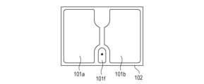
- 4A and 4B are diagrams illustrating the bonding surface of a power supply member, illustrating the general structure of a rectangular piezoelectric element.
- 4A and 4B are diagrams illustrating an elastic body bonding surface, illustrating a schematic structure of a rectangular piezoelectric element.
- 1A and 1B are diagrams illustrating two vibration modes (mode A) generated by a vibrator of the present invention having a rectangular piezoelectric material.
- 1A and 1B are diagrams illustrating two vibration modes (mode B) generated by a vibrator of the present invention having a rectangular piezoelectric material.
- 1 is a diagram illustrating a schematic structure of an optical device according to the present invention.
- the vibration actuator of the present invention is a vibration actuator that includes a vibrating body having a conductive elastic body and a piezoelectric element provided on the elastic body, and a contact body in contact with the elastic body, and the vibrating body and the contact body move relatively due to vibration of the vibrating body.
- the plate-shaped piezoelectric material that constitutes the piezoelectric element has a through-hole that penetrates the piezoelectric material in the thickness direction and a through-hole electrode filled in the through-hole.
- the through-hole electrode has a protruding portion that protrudes from a first opening of the through-hole, and a ground electrode that is conductive with the through-hole is provided on the surface of the piezoelectric material on the side of the first opening.
- the through-hole electrode and the elastic body are characterized in that they are conductive with each other.
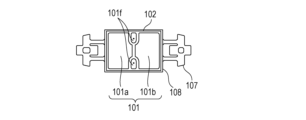
- vibration Actuator 1A to 1F show examples of schematic structures of vibration actuators according to the present invention.
- the vibration actuator 100 of the present invention comprises a vibrator 102 in which an electrode 101, a piezoelectric material 102, and an elastic body 103 are arranged in this order, and a contact body 104 that contacts the elastic body 103.
- the elastic body 103 and the piezoelectric material 102 are joined via an adhesive part 105.
- the elastic body 103 has a protrusion 106, and the protrusion 106 and the contact body 104 are in pressure contact.
- the contact body 104 may be any member that can move relative to the vibrator 110, and is not limited to being in direct contact with the vibrator 110, but may be indirectly in contact with the vibrator 110 via another member.
- the "contact body” refers to a member that comes into contact with the vibrator and moves relative to the vibrator due to vibrations generated in the vibrator.
- the contact between the contact body and the vibrator is not limited to direct contact with no other member between the contact body and the vibrator.
- the contact between the contact body and the vibrator may be indirect contact with another member between the contact body and the vibrator, as long as the contact body moves relative to the vibrator due to vibrations generated in the vibrator.
- the “other member” is not limited to a member independent of the contact body and the vibrator (for example, a high-friction material made of a sintered body).
- the “other member” may be a surface treatment portion formed on the contact body or the vibrator by plating, nitriding, or the like.
- the piezoelectric material 102 constituting the piezoelectric element includes piezoelectric ceramics (sintered body) without crystal orientation, crystal oriented ceramics, and piezoelectric single crystals.
- the thickness of the piezoelectric material is processed to a design value within the range of approximately 0.3 to 0.5 mm.
- the piezoelectric material 102 is provided with at least one through-hole that penetrates in the thickness direction and one through-hole electrode that is filled in the through-hole.
- the through-holes can be arranged symmetrically within the piezoelectric material, or, to reduce the manufacturing costs of the element, a configuration in which only one through-hole is provided for one ground electrode can be adopted.
- the diameter of the through-hole is preferably in the range of 50 to 200 microns.
- Figures 2A to 2D show examples of schematic cross-sectional structures of through-holes provided in a piezoelectric material suitable for the vibration actuator of the present invention.
- a lapping process is applied to the surface of the piezoelectric material provided with the through-hole electrode in order to flatten the surface of the piezoelectric element and adjust the thickness (protrusion amount or height) of the protruding portion of the through-hole electrode.
- a protruding portion of the through-hole electrode is formed in the first opening that opens on the elastic body side of the through-hole.
- the amount of protrusion of the protrusion i.e., the height from the surface of the piezoelectric material to the tip of the through-hole electrode, varies depending on the grit of the media (e.g., silicon carbide) used in the lapping process, and can be adjusted by the grit of the media. For example, the larger the grit of the media, the smaller the amount of protrusion.
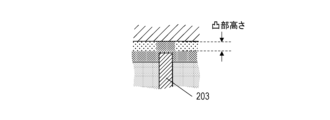
- Figure 2A shows the through-hole electrode 203 filled in the through-hole provided in the piezoelectric material 202 protruding from the first opening that opens on the elastic body side of the piezoelectric element, and is lapped so that it protrudes by the thickness sandwiched between the dashed lines.
- Figure 2A shows the state before the lapping process is performed, and the height direction is exaggerated to illustrate the protrusion of the through-hole electrode.
- the through-hole electrode 203 above the upper of the two dashed lines is removed by the lapping process.
- the protrusion amount of the protruding portion 201 of the through-hole electrode 203 sandwiched between the dashed lines is preferably 0.5 microns or more and less than 10 microns. If the protrusion amount is 10 microns or less, the thickness of the adhesive layer can be 10 microns or less, and the vibration efficiency of the vibration actuator can be kept sufficiently good. On the other hand, if the protrusion amount is 10 microns or more, the thickness of the adhesive layer is greater than 10 microns, which may significantly reduce the vibration efficiency of the vibration actuator. Furthermore, the inclination of the elastic body relative to the surface of the piezoelectric material becomes large, which may cause differences in the movement speed of the contact body depending on the direction of travel.
- the protrusion amount it is even more preferable for the protrusion amount to be 5 microns or less. This is because if the protrusion amount is 5 microns or less, the thickness of the adhesive layer will be thinner than 5 microns, and the vibration efficiency of the vibration type actuator can be maintained at a better level.
- the through-hole electrodes In addition to inexpensive silver, silver-palladium, platinum, etc. can be used for the through-hole electrodes.
- the through-hole electrode material When the piezoelectric material and the through-hole electrodes are co-fired, the through-hole electrode material must not melt during the firing process of the piezoelectric material. For this reason, the through-hole electrode material is selected according to the firing temperature of the piezoelectric material, and when the firing temperature exceeds 1300°C, an electrode material whose main component is platinum is used. Main component refers to a weight percent concentration of 90% or more.
- Main component refers to a weight percent concentration of 90% or more.
- the through-hole electrode can also be formed in the through-hole after the piezoelectric material is fired.
- FIG. 2B is an enlarged cross-sectional view showing the state after the through-holes in the piezoelectric material are filled with through-hole electrodes 203, lapping is performed, the ground electrode 204 is formed, and the elastic body 206 and the piezoelectric element are bonded via the adhesive layer 205.
- the ground electrode 204 and through-hole electrode 203 provided after lapping come into contact with the surface of the piezoelectric material on the first opening side, and are electrically connected to each other.
- FIG. 2B shows a case where the thickness of the ground electrode 204 is smaller than the protrusion of the through-hole electrode 203, and the through-hole electrode 203 comes into contact with the elastic body 206, and is electrically connected to each other.
- the through-hole electrode 203 is covered with the ground electrode, and the ground electrode forms a convex portion on the protruding portion.
- the convex portion of the ground electrode may be in contact with the elastic body as shown in FIG. 2C, and the ground electrode may be configured to be conductive with the elastic body.
- the amount of protrusion of the through-hole electrode may also be replaced by the height of the convex portion of the ground electrode. Note that it is possible to confirm that the through-hole electrode is covered with the ground electrode by detecting the constituent elements of the ground electrode between the top of the protruding portion of the through-hole electrode and the elastic body 206.
- the elastic body 103 and the piezoelectric material 102 are bonded via an adhesive layer 205.
- adhesive layer 205 There are no particular limitations on the type of adhesive, but epoxy resin is preferred because it has excellent strength, a short curing time, and is stable even in high temperature and high humidity environments. General epoxy resins are insulating.
- the piezoelectric element does not have the protrusion, increasing the pressure applied when bonding the ground electrode and the elastic body in order to establish electrical conductivity between the ground electrode and the elastic body will significantly thin the adhesive layer and cause parts of the adhesive layer to disappear. As a result, the adhesive strength between the elastic body and the piezoelectric element will decrease, causing peeling during operation of the vibration actuator and resulting in malfunction.
- an adhesive layer is provided between the elastic body and the ground electrode without providing a protrusion on the through-hole electrode, there will be no electrical conductivity between the elastic body and the ground electrode ( Figure 2D). As a result, polarization defects will cause the vibration actuator to malfunction and may also reduce yields.
- a gap is provided between the ground electrode and the elastic body according to the amount of protrusion.
- the gap becomes a space that holds an adhesive material containing an insulating material, and by forming an adhesive layer, the adhesive strength between the piezoelectric element and the elastic body is increased.
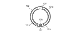
- the piezoelectric material consists of a driving phase electrode 101e and a non-driving phase electrode 101f that are divided in the circumferential direction ( Figure 3A).
- the circumferential length of the driving phase electrode is 1/2 the wavelength ⁇ of the driving frequency.
- the circumferential length of the non-driving phase electrode is 1/4 the wavelength ⁇ of the driving frequency.
- the number of driving phase electrodes and non-driving phase electrodes changes according to the number of traveling waves excited in the circular piezoelectric material.
- the piezoelectric material corresponding to each driving phase electrode is polarized with a voltage of a different polarity from that of adjacent regions.
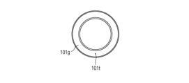
- a circular ground electrode 101g is provided on the surface facing electrodes 101e and 101f (FIG. 3B). At least one of the non-driving phase electrodes provided on the same surface as the driving phase electrode 101e is electrically connected to the ground electrode 101g via a through-hole electrode 101t.
- the shape of the power supply member can be made into a simple, planar structure.
- the driving phase electrodes are separated by an odd number of non-driving phase electrodes.
- An elastic body is bonded to the piezoelectric element, and then a high voltage is applied between the driving phase electrode 101e and the elastic body to polarize the annular piezoelectric material.
- a first electrode 101a and a second electrode 101b are provided to short-circuit the two driving phase electrode groups separated by the non-driving phase electrodes.
- the first electrode 101a and the second electrode 101b are formed at a temperature lower than the depolarization temperature of the piezoelectric material.
- the first electrode 101a and the second electrode 101b are used to drive a vibration type actuator using the annular piezoelectric material.
- FIG. 4A and 4B one through-hole electrode is provided.
- the through-hole electrode is indicated by a black dot in the figure, and the black dot in Figure 4A and the black dot in Figure 4B indicate the top of the through-hole electrode 203 as seen into one opening of the same through-hole and the other opening facing the other.
- the arrangement of through-hole electrodes is not symmetrical with respect to a center line drawn horizontally on the page for the piezoelectric material 102 in the figure for a rectangular piezoelectric element, but it has lower manufacturing costs compared to piezoelectric elements with multiple through-hole electrodes.
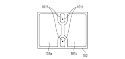
- Figures 4C and 4D it is also possible to arrange the through-hole electrodes so that they are substantially symmetrical about the center line in order to improve the vibration quality of the vibration waves generated by the vibrating body.
- Figures 4C and 4D show a rectangular piezoelectric element provided with two through-hole electrodes. By providing two through-hole electrodes, the electrode arrangement becomes symmetrical about the line, and the symmetry of the vibration generated by the piezoelectric element is improved.
- the rectangular piezoelectric material is provided with a first electrode 101a, a second electrode 101b, and a non-driving phase electrode 101f ( Figures 4A and 4C).
- the first electrode 101a and the second electrode 101b are polarized with a voltage of the same polarity and are used to drive a vibration type actuator using the rectangular piezoelectric material.
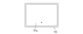
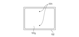
- a rectangular ground electrode 101g is provided on the surface facing the first electrode 101a and the second electrode 101b. At least one of the non-driving phase electrodes 101f provided on the same surface as the driving phase electrodes 101a and 101b is electrically connected to the ground electrode 101g via a through-hole electrode 101t ( Figures 4B and 4D).
- the surface electrodes formed on the surface of the piezoelectric material i.e., the driving phase electrode, non-driving phase electrode, ground electrode, first electrode, and second electrode excluding the through-hole electrodes, are made of a metal film having a thickness of 0.3 to 10 ⁇ m.
- the material is not particularly limited, but silver, silver-palladium, or gold is generally used. Electrodes mainly composed of inexpensive silver are most preferable. A surface electrode thickness of less than 5 microns is preferable as it suppresses interference with the vibration efficiency of the piezoelectric element.
- the elastic body of the present invention is conductive and is electrically connected to the ground electrode. Therefore, when performing polarization treatment on the piezoelectric material, the elastic body can be used as an electrode.
- a voltage is applied to the driving phase electrode 101e and the non-driving phase electrode 101f that are not electrically connected to the ground electrode 101g, and the elastic body is grounded.
- a voltage is applied to the first electrode 101a and the second electrode 101b, and the elastic body is grounded.
- the elastic body 103 is made of a metal.
- metals that can be used for the elastic body 103 include aluminum, brass, and stainless steel. Among stainless steels, martensitic stainless steel is preferable, and SUS420J2 is most preferable (resistivity at room temperature is 55 ⁇ cm).
- the elastic body has a protrusion 106 that contacts the contact body. When the elastic body is hardened to improve the wear resistance of the protrusion, the hardening process is performed in a vacuum to prevent the formation of an oxide film that increases electrical resistance. SUS420J2 that has been hardened in a vacuum has high hardness and is suitable for the vibration type actuator of the present invention, which drives the contact body by friction with the elastic body.
- the thickness of the elastic body to be bonded to the rectangular piezoelectric material is preferably in the range of 0.2 to 0.35 mm, as this provides both rigidity and springiness and is easy to mold.
- the contact body 104 is preferably made of stainless steel. Among stainless steels, martensitic stainless steel is preferable, and SUS420J2 is most preferable.
- the contact body 104 must have excellent wear resistance because it is in frictional contact with the elastic body 103, and its surface is subjected to a nitriding treatment. A frictional force due to pressurized contact acts between the protrusion 106 and the contact body 104. The vibration generated by the piezoelectric material 102 causes the tip of the protrusion 106 to vibrate elliptically, generating a driving force (thrust) that drives the contact body 104.
- the contact body is generally called a slider or rotor.
- the piezoelectric material in contact with the adjacent driving phase electrodes is polarized with different polarities, so when an electric field of the same polarity is applied to the driving phase electrode 101e, the expansion and contraction polarity in the corresponding region of the piezoelectric material is alternately reversed at a pitch of ⁇ /2.
- a first standing wave with a wavelength ⁇ is generated over the entire circumference of the vibrator.
- a second standing wave is generated in the same manner, but the position of the wave is rotated by ⁇ /4 in the circumferential direction relative to the first standing wave.
- two types of alternating voltages with the same frequency and a temporal phase difference of ⁇ /2 are applied to the first and second electrodes.
- a traveling wave wave number n along the annulus, wavelength ⁇
- bending vibration vibration with amplitude perpendicular to the surface of the vibrator
- each point on the surface of the diaphragm that constitutes the vibrator moves elliptically, and a moving body in contact with this surface rotates due to the circumferential frictional force (driving force) applied from the diaphragm.
- the direction of rotation can be reversed by switching the positive/negative phase difference of the alternating voltage applied to the first electrode and the second electrode.
- the rotation speed can also be controlled by the frequency and amplitude of the alternating voltage applied to the first electrode and the second electrode.
- FIG. 5A and 5B explain two vibration modes generated by the vibrator of the present invention having a rectangular piezoelectric material.
- the regions where the first electrode and the second electrode are provided are the first region and the second region, respectively.
- the structure of the vibration type actuator is as shown in FIG. 1A, FIG. 1E, and FIG. 1F, respectively.
- Mode A When both the first region and the second region expand or contract, a first bending vibration mode (mode A) is generated. Mode A is excited most strongly when the phase difference between the alternating voltages V A and V B applied to the first electrode 101a and the second electrode 101b is 0° and the frequency is near the resonant frequency of mode A. Mode A is a primary out-of-plane vibration mode in which two nodes (where the amplitude is minimum) appear approximately parallel to the long side of the vibrator 110. The protrusion 106 of the elastic body is disposed near the position that is the antinode (where the amplitude is maximum) of mode A. Therefore, the tip surface of the protrusion 106 reciprocates in the Z direction due to vibration mode A.
- Mode B When the first region expands and contracts, the second region contracts and expands, respectively, generating a second bending vibration mode (mode B). Mode B is most strongly excited when the phase difference between the alternating voltages V A and V B applied to the first electrode 101a and the second electrode 101b is 180° and the frequency is near the resonant frequency of mode B. Mode B is a secondary out-of-plane vibration mode in which three nodes appear approximately parallel to the short side of the vibrator 110. The protrusion 106 of the elastic body is disposed near the node position of mode B. Therefore, the tip surface of the protrusion 106 reciprocates in the X direction due to mode B.
- the vibrator is supported by a fitting hole provided in a support part 107 that protrudes from the end of a rectangular part 108.
- the support part 107 can be omitted and the rectangular part 108 of the elastic body can be held.
- the piezoelectric material contains less than 1000 ppm of lead.
- the main component of the piezoelectric material is a barium titanate-based material.
- barium titanate-based materials include barium titanate (BaTiO 3 ), barium calcium titanate ((Ba,Ca)TiO 3 ), barium zirconate titanate (Ba(Ti,Zr)O 3 ), and barium calcium zirconate titanate ((Ba,Ca)(Ti,Zr)O 3 ).
- compositions such as sodium niobate-barium titanate (NaNbO 3 -BaTiO 3 ), sodium bismuth titanate-barium titanate ((Bi 0.5 Na 0.5 )TiO 3 -BaTiO 3 ), and potassium bismuth titanate-barium titanate ((Bi 0.5 K 0.5 )TiO 3 -BaTiO 3 ). It refers to materials that have these compositions as their main components. Among them, the following materials are preferable from the viewpoint of achieving both the piezoelectric constant and mechanical quality factor of the piezoelectric material.
- a main component refers to a material whose weight fraction is greater than 90%.
- the lead content of the piezoelectric material is 1000 ppm or less, it is more preferable because it has a small environmental impact.
- lead zirconate titanate (Pb(Zr,Ti) O3 ) containing lead is widely used in piezoelectric devices.
- the piezoelectric material of the present invention is a barium titanate-based piezoelectric material with a lead content of less than 1000 ppm.
- the lead content can be measured, for example, by ICP atomic emission spectrometry.
- the main component of the piezoelectric material is preferably barium calcium zirconate titanate (hereinafter referred to as BCTZ).
- BCTZ barium calcium zirconate titanate
- the piezoelectricity of BCTZ can be adjusted according to the application by adjusting the amount of Ca and Zr. In addition, the amount of expensive niobium used can be reduced.
- the piezoelectric material is a piezoelectric material containing an oxide of a perovskite structure containing Ba, Ca, Ti, and Zr, and Mn, and the molar ratio x of the Ca to the sum of the Ba and the Ca is 0.02 ⁇ x ⁇ 0.30, the molar ratio y of the Zr to the sum of the Ti and the Zr is 0.020 ⁇ y ⁇ 0.095 and y ⁇ x, the ratio ⁇ of the molar amounts of the Ba and Ca to the molar amounts of the Ti and Zr is 0.9955 ⁇ 1.01, and the content of the Mn relative to 100 parts by weight of the oxide is preferably 0.02 parts by weight or more and 1.0 parts by weight or less in terms of metal.
- Such a piezoelectric material can be represented by the following general formula (1). (Ba1 -xCax ) ⁇ (Ti1 - yZry ) O3 (1) however, 0.986 ⁇ 1.100, 0.02 ⁇ x ⁇ 0.30, 0.02 ⁇ y ⁇ 0.095 and the content of metal components other than the main component contained in the piezoelectric material is preferably 1 part by weight or less in terms of metal per 100 parts by weight of the metal oxide.
- the metal oxide contains Mn, and the content of the Mn is 0.02 parts by weight or more and 0.40 parts by weight or less in terms of metal per 100 parts by weight of the metal oxide.
- Mn is contained within the above range, the insulation properties and the mechanical quality coefficient Qm are improved.
- the mechanical quality coefficient Qm is a coefficient that represents the elastic loss due to vibration when the piezoelectric material is evaluated as a vibrator, and the magnitude of the mechanical quality coefficient is observed as the sharpness of the resonance curve in impedance measurement. In other words, it is a constant that represents the sharpness of the resonance of the vibrator.
- the mechanical quality coefficient Qm is large, the amount of distortion of the piezoelectric material becomes larger near the resonance frequency, and the piezoelectric material can be vibrated effectively.
- the metal oxide represented by the general formula (1) means that the metal elements located at the A site of the perovskite structure are Ba and Ca, and the metal elements located at the B site are Ti and Zr. However, some of the Ba and Ca may be located at the B site. Similarly, some of the Ti and Zr may be located at the A site.
- the molar ratio of the B site element to the O element is 1:3, but even if the molar ratio is slightly different, it is still within the scope of the present invention as long as the metal oxide has a perovskite structure as the main phase.
- a metal oxide has a perovskite structure can be determined, for example, by structural analysis using X-ray diffraction or electron diffraction.
- x which indicates the molar ratio of Ca at the A site, is in the range of 0.02 ⁇ x ⁇ 0.30.
- the phase transition temperature between the orthorhombic and tetragonal crystals shifts to the lower temperature side, so stable piezoelectric vibration can be obtained in the driving temperature range of the vibration actuator.
- x is greater than 0.30, the piezoelectric constant of the piezoelectric material will be insufficient, and the performance of the vibration actuator may be insufficient.
- x is less than 0.02, the dielectric loss (tan ⁇ ) may increase. If the dielectric loss increases, heat generation increases when a voltage is applied to the piezoelectric material to drive the vibration actuator, the motor driving efficiency decreases, and power consumption may increase.
- y which indicates the molar ratio of Zr in the B site, is in the range of 0.02 ⁇ y ⁇ 0.1. If y is greater than 0.1, Td will be low, less than 80°C, and the temperature range in which the vibration actuator can be used will be less than 80°C, which is undesirable.
- Td refers to the lowest temperature at which the piezoelectric constant after heating the piezoelectric material from room temperature to Td one week after polarization processing and then cooling it back to room temperature drops by more than 10% compared to the piezoelectric constant before heating.
- ⁇ which indicates the ratio of the molar amounts of Ba and Ca at the A site to the molar amounts of Ti and Zr at the B site, is preferably in the range of 0.9955 ⁇ 1.010. If ⁇ is smaller than 0.9955, abnormal grain growth is likely to occur in the crystal grains that make up the piezoelectric material, and the mechanical strength of the piezoelectric material decreases. On the other hand, if ⁇ is larger than 1.010, the piezoelectric material does not become highly densified and its insulation becomes extremely brittle.
- the means for measuring the composition of the piezoelectric material there are no particular limitations on the means for measuring the composition of the piezoelectric material. Examples of such means include X-ray fluorescence analysis, ICP atomic emission spectrometry, and atomic absorption spectrometry. Regardless of the measurement means used, the weight ratio and composition ratio of each element contained in the piezoelectric material can be calculated.
- the metal equivalent showing the Mn content is calculated by calculating the content of each metal, Ba, Ca, Ti, Zr and Mn, measured from the piezoelectric material using X-ray fluorescence analysis (XRF), ICP atomic emission spectrometry, atomic absorption spectrometry, etc. From that content, the elements constituting the metal oxide represented by general formula (1) are converted to oxides, and the value is calculated as the ratio of the weight of Mn to the total weight of 100.
- XRF X-ray fluorescence analysis
- ICP atomic emission spectrometry ICP atomic emission spectrometry
- atomic absorption spectrometry atomic absorption spectrometry
- Mn is not limited to metallic Mn, and it is sufficient that it is contained in the piezoelectric material as an Mn component, and the form of its inclusion does not matter. For example, it may be solid-dissolved in the B site, or it may be contained in the grain boundaries. A more preferable form of inclusion is solid-dissolved in the B site from the standpoint of insulation properties and ease of sintering.
- the piezoelectric material contains 0.042 parts by weight or more and 0.850 parts by weight or less of Bi, calculated as metal.
- the piezoelectric material may contain 0.85 parts by weight or less of Bi in terms of metal, relative to 100 parts by weight of the metal oxide represented by the general formula (1).
- the content of Bi relative to the metal oxide can be measured, for example, by ICP emission spectroscopy.
- Bi may be present at the grain boundary of the ceramic piezoelectric material, or may be dissolved in the perovskite structure of (Ba, Ca) (Ti, Zr) O 3.
- Bi When Bi is present at the grain boundary, friction between particles is reduced and the mechanical quality factor is increased.
- Bi when Bi is incorporated into a solid solution that forms a perovskite structure, the phase transition temperature is lowered, so that the temperature dependence of the piezoelectric constant is reduced and the mechanical quality factor is further improved.
- Bi is incorporated into the solid solution, it is preferable that the position of Bi is the A site, since the charge balance with the Mn is improved.
- the piezoelectric material may contain components (hereinafter, subcomponents) other than the elements contained in the general formula (1) and Mn and Bi within a range that does not change the characteristics.
- the total amount of the subcomponents is preferably less than 1.2 parts by weight per 100 parts by weight of the metal oxide expressed by the general formula (1). If the amount of the subcomponents exceeds 1.2 parts by weight, the piezoelectric properties and insulating properties of the piezoelectric material may be deteriorated.
- the Curie temperature of (Ba,Ca)(Ti,Zr) O3 is in the range of 85°C to 126°C.
- the vibration actuator of the present invention has a power supply member joined to a piezoelectric element having the piezoelectric material and the electrodes.
- the power supply member is preferably a flexible printed circuit board (hereinafter FPC) because of its high dimensional accuracy and ease of positioning.
- FPC flexible printed circuit board
- the material is preferably polyimide.
- ACP anisotropic conductive paste
- ACF anisotropic conductive film
- Supplying power through the FPC allows power to be supplied without impeding the vibration of the piezoelectric element.
- the FPC is connected to at least the first electrode and the second electrode, and may also be connected to the non-driving phase electrode.
- the method for manufacturing piezoelectric elements is as follows. First, the raw powder of piezoelectric material is molded using a sheet molding method to create a green sheet with a thickness of 30 to 200 microns. Next, the positions for forming the through holes are determined taking into consideration factors such as shrinkage during firing and cutting margins during dicing, and the green sheet is punched with a punch with a diameter of, for example, 150 microns to form the through holes.
- the through-hole electrode paste into the through-hole.
- a heat-resistant material that will not melt during the firing process is selected for the through-hole electrode material.
- the aforementioned (Ba,Ca)(Ti,Zr)O 3 requires a firing temperature of at least 1300°C, so a material containing platinum as the main component is used for the through-hole electrode.
- the aforementioned NaNbO 3 -BaTiO 3 requires a firing temperature of 1200 to 1260°C, so Ag-Pd (e.g. 0.5Ag-0.5Pd) is used for the through-hole electrode.
- the required number of green sheets are stacked and compressed, taking into consideration shrinkage during firing and the margin for scraping during the lapping process.
- the through-holes are aligned in the stacking direction so that the through-hole electrodes do not break.
- the laminated and pressed molded body is fired, and then a lapping process is performed to adjust the thickness of the piezoelectric material.
- the amount of protrusion of the through-hole electrode changes depending on the lapping conditions at this time.
- the amount of protrusion varies depending on the lapping conditions such as the grit (grain size) of the abrasive, the work load, and the rotation speed of the platen, but is most dependent on the grit. The lower the grit, the greater the amount of protrusion.
- the surface electrodes are printed and baked.
- the piezoelectric material with the surface electrodes is then diced to separate into individual element pieces.
- the dimensions of the rectangular piezoelectric element of the present invention are 9 mm x 6 mm, and the thickness is 0.3 to 0.45 mm.
- the manufacturing method of the vibrator constituting the vibration type actuator of the present invention is as follows. First, a step of bonding a piezoelectric element and an elastic body with an adhesive at temperature T1, and a step of bonding the piezoelectric element and a power supply member at temperature T2 are carried out. Then, a step of applying a voltage between the electrode and the elastic body and carrying out a polarization process at temperature T3 are carried out in this order to manufacture the vibrator.
- the T1, T2, and T3 satisfy the relationships T1>T3 and T2>T3.
- the electronic device of the present invention is characterized by comprising the above-mentioned vibration actuator, a member connected to the contact body of the vibration actuator, and a member position detection means (e.g., an encoder).
- the electronic device detects the position of the member and operates the vibration actuator until the member reaches a target position, thereby enabling precise control of the position of the member.
- the optical apparatus of the present invention includes the vibration actuator described above in a drive section, and further includes at least one of an optical element and an imaging element.
- FIG. 5A and 5B are schematic diagrams showing an embodiment of the optical device (focus lens part of the lens barrel device) of the present invention.
- the vibrator 110 having a rectangular piezoelectric material is in pressure contact with the contact body (slider) 104 as in FIG. 1D.
- the power supply member 507 is connected to the surface side having the first and second regions.
- a voltage input means not shown
- an elliptical motion is generated in the protrusion of the elastic body (not shown).
- the holding member 501 is joined to the vibrator 110 and is configured not to generate unnecessary vibrations.
- the moving housing 502 is fixed to the holding member 501 with a screw 503 and is integrated with the vibrator 110. These members form the electronic device of the present invention. By attaching the moving housing 502 to the guide member 504, the electronic device of the present invention can move linearly in both directions (forward and reverse) along the guide member 504.
- the lens 506 (optical member) that serves as the focus lens of the telescope barrel device.
- the lens 506 is fixed to the lens holding member 505, and has an optical axis (not shown) parallel to the movement direction of the vibration actuator.
- the lens holding member 505 moves linearly on two guide members 504 (described below) to perform focal position adjustment (focus operation).
- the two guide members 504 are members that engage the movable housing 502 and the lens holding member 505, enabling the movable housing 502 and the lens holding member 505 to move linearly. With this configuration, the movable housing 502 and the lens holding member 505 can move linearly on the guide members 504.
- the connecting member 510 is a member that transmits the driving force generated by the vibration actuator to the lens holding member 505, and is fitted and attached to the lens holding member 505. This allows the lens holding member 505 to move smoothly in both directions along the two guide members 504 together with the movable housing 502.
- the sensor 508 is provided to detect the position of the lens holding member 505 on the guide member 504 by reading the position information of a scale 509 attached to the side of the lens holding member 505.
- the focus lens section of the telescope barrel device is constructed by incorporating each of the above-mentioned components.
- a lens barrel device for a single-lens reflex camera has been described as an example of an optical device, but the device can be applied to a variety of optical devices equipped with a vibration actuator, regardless of the type of camera, such as a compact camera in which the lens and camera body are integrated, or an electronic still camera.
- Another configuration of the vibration actuator may be one in which multiple vibrators are in contact with a common contact body, and the contact body moves relative to the multiple vibrators as the multiple vibrators vibrate.
- vibration actuator of the present invention applications in the medical or engineering fields are conceivable. Specifically, it is possible to configure a wire-driven actuator that has an elongated member, a wire that is inserted through the elongated member and fixed to a part of the elongated member, and the above-mentioned vibration actuator that drives the wire, and in which the elongated member is curved by driving the wire.
- a piezoelectric element with a protruding through-hole electrode was fabricated according to the manufacturing method for the piezoelectric element described above.
- the relationship between the size of the media used to lap the piezoelectric material and the protruding amount of the through-hole electrode is shown in Table 1.
- Example 1 A circular ring-shaped compact of (Ba,Ca)(Ti,Zr) O3 with a through-hole electrode was sintered at 1340°C.
- the thickness of the piezoelectric material of the obtained sintered body was adjusted to 0.5 mm using silicon carbide powder of No. 4000.
- the protrusion amount of the through-hole electrode was 1 to 3 microns.
- the inner and outer diameters were also ground to process it into a circular ring with an outer diameter of 62 mm and an inner diameter of 54 mm.
- the driving phase electrode 101e and non-driving phase electrode 101f shown in Figure 3A were formed on one side of the shaped piezoelectric material 102.
- the driving phase electrode 101e and the non-driving phase electrode 101f are printed so that the middle non-driving phase electrode and the through-hole are joined.
- the ground electrode 101g in Figure 3B is conductive with one of the non-driving phase electrodes 101f via the through-hole electrode 101t.
- the surface electrodes formed by the screen printing method are dried and then baked at 600 to 850°C. The thickness of the silver surface electrode after baking was 6 microns.
- the FPC coated with ACP was thermocompressed to the electrodes on the piezoelectric material.
- the elastic body SUS420J2 was grounded, and voltages of different polarities were alternately applied to adjacent driving phase electrodes 101e to perform polarization processing.
- the polarization processing multiple external electrodes connected to a power source were brought into contact with the driving phase electrode 101e and the electrode of the driven phase electrode 101f that is not conductive with the installation electrode 101t and is used as a sensor.
- the first electrode 101a and the second electrode 101b were printed and dried to obtain a vibrator.
- the temperature of the piezoelectric material was kept below 80°C to prevent depolarization of the piezoelectric material.
- the obtained vibrator was pressed into contact with a contact body (rotor) made of SUS420J2 to create a vibration actuator.
- Example 2 A plate-shaped molded body of (Ba,Ca)(Ti,Zr) O3 provided with a through-hole electrode was sintered at 1340°C.
- the composition of the through-hole electrode was platinum.
- the thickness of the piezoelectric material of the obtained sintered body was adjusted to 0.4 mm using 4000-number silicon carbide powder.
- the protrusion amount of the through-hole electrode was 1 to 3 microns.
- the first electrode 101a, the second electrode 101b, and the non-driving phase electrode 101f shown in FIG. 4A were printed and dried.
- the installation electrode 101g was printed and dried on the opposite side of the piezoelectric material.
- the surface electrode was baked at 600 to 850°C.
- the thickness of the silver surface electrode after baking was 3 microns.
- the ground electrode 101g was conductive with the non-driving phase electrode 101t via the through-hole electrode 101t. Thereafter, the piezoelectric material having the surface electrodes formed thereon was cut into individual pieces of 8.9 mm ⁇ 5.7 mm using a dicing device, to obtain the rectangular piezoelectric elements shown in FIG. 4A.
- an epoxy-based thermosetting adhesive was applied to the elastic body 103 shown in Figure 1E, which was made of SUS420J2, and it was pressed against the piezoelectric material 102 on which the electrodes were formed.
- a heat treatment was carried out to harden the adhesive.
- the FPC coated with ACP was thermocompressed to the non-driving phase electrode provided on the piezoelectric material to produce a vibrator.
- the elastic body SUS420J2 was grounded, and a voltage of the same polarity was applied to the first electrode 101a and the second electrode 101b to perform polarization processing.
- the polarization processing two external electrodes connected to a power source were brought into contact with the first electrode 101a and the second electrode 101b.
- the obtained vibrator was pressurized and brought into contact with a contact body (rotor) made of SUS420J2 to produce a vibration type actuator.
- Example 3 A vibration type actuator was produced in the same manner as in Example 2, except that #2000 silicon carbide powder was used to wrap the sintered body.
- the protrusion amount of the through-hole electrode was 3 to 5 microns.
- Example 4 A vibration type actuator was produced in the same manner as in Example 2, except that #1000 silicon carbide powder was used to wrap the sintered body.
- the protrusion amount of the through-hole electrode was 5 to 10 microns.
- Example 5 A plate-shaped molded body of 0.88NaNbO 3 -0.12BaTiO 3 provided with a through-hole electrode was sintered at 1260°C.
- the composition of the through-hole electrode was 5Ag-5Pd, a mixture of silver and palladium in a molar ratio of 1:1.
- the thickness of the piezoelectric material of the obtained sintered body was adjusted to 0.35 mm using silicon carbide powder of No. 4000. At this time, the protrusion amount of the through-hole electrode was 1 to 3 microns.
- the installation electrode 101g was printed on the opposite side of the piezoelectric material and dried.
- the surface electrode was baked at 600 to 850°C.
- the ground electrode 101g was conductive to the non-driving phase electrode 101t via the through-hole electrode 101t.
- the piezoelectric material having the surface electrodes formed thereon was cut into individual pieces of 8.5 mm ⁇ 5.7 mm using a dicing device, to obtain the rectangular piezoelectric elements shown in FIG. 4C.
- thermosetting adhesive was applied to the elastic body 103 shown in Fig. 1E, which was made of SUS420J2, and the elastic body was pressed against the piezoelectric material 102 of 0.88NaNbO3-0.12BaTiO3 on which electrodes were formed.
- a heat treatment was carried out to harden the adhesive.
- the FPC coated with ACP was thermocompressed to the non-driving phase electrode provided on the piezoelectric material to produce a vibrator.
- the elastic body SUS420J2 was grounded, and a voltage of the same polarity was applied to the first electrode 101a and the second electrode 101b to perform polarization processing.
- the polarization processing two external electrodes connected to a power source were brought into contact with the first electrode 101a and the second electrode 101b.
- the contact body When the frequency of the alternating voltage is swept from a frequency higher than the resonant frequency of vibration mode A and vibration mode B toward the resonant frequency, the contact body is driven in a direction according to the phase difference of the alternating voltage and stops after reaching maximum speed.
- the directions of travel when the phase difference is -90° and 90° are called the reverse direction and forward direction, respectively.
- the maximum speed of the vibrator and the frequency at which the maximum speed was reached were measured with a sensor.
- the power (rated power) at a rated speed lower than the maximum speed was calculated from the current flowing through the drive circuit.
- the rated power of the vibration actuators of Examples 2 and 3 was approximately 10% lower than that of the vibration actuator of Example 4, and was generally the same.
- the drive characteristics of the vibration actuators of Examples 2 to 4 were evaluated for durability by performing continuous reciprocating motion, and no significant deterioration in the drive characteristics was observed even after the test.
- (Comparative Example 1) A green sheet of (Ba,Ca)(Ti,Zr) O3 with a thickness of about 130 microns was prepared. After forming through holes in the green sheet with a punch, the green sheets were laminated, pressed, and sintered at 1340°C without printing through-hole electrodes. The obtained sintered body was adjusted to a thickness of 0.4 mm using silicon carbide powder of No. 4000. The first electrode 101a, the second electrode 101b, and the non-driving phase electrode 101f shown in FIG. 4A were printed and dried on one side of the plate-shaped piezoelectric material 102 with the adjusted thickness. Next, the installation electrode 101g was printed and dried on the opposite side of the piezoelectric material.
- the electrodes are filled in the through-holes through the printing process of these surface electrodes.
- the surface electrode and the through-hole electrode were baked at 600 to 850°C.
- the protrusion amount of the through-hole electrode was 0 microns or less.
- the ground electrode 101g was conductive with the non-driving phase electrode 101t via the through-hole electrode 101t.
- the piezoelectric material having the surface electrodes formed thereon was cut into individual pieces of 8.9 mm ⁇ 5.7 mm using a dicing device, to obtain the rectangular piezoelectric elements shown in FIG. 4A.
- an epoxy-based thermosetting adhesive was applied to the elastic body 103 shown in Figure 1E, which was made of SUS420J2, and it was pressed against the piezoelectric material 102 on which the electrodes were formed.
- a heat treatment was carried out to harden the adhesive.
- Example 6 The vibration actuator produced in Example 2 was mechanically connected to an optical member to produce the optical device shown in Fig. 6.
- an optical lens was connected to the vibration actuator, and it was confirmed that it had an autofocus function.
- the elastic body and the ground electrode are electrically connected. Therefore, no polarization defects occur in the process of grounding the elastic body and performing a polarization process on the piezoelectric material, and vibration actuators can be manufactured with a good yield.
- the vibration actuator of the present invention can be used for a variety of purposes, such as driving lenses and image pickup elements in imaging devices (optical equipment), driving the rotation of photosensitive drums in copiers, and driving stages. Although a single vibration actuator has been described in this specification, it is also possible to arrange multiple vibration actuators in a circular ring shape to drive the rotation of a ring-shaped contact body.
Abstract
The present invention provides a vibratory actuator in which electrical contact between a piezoelectric element and an elastic body is sufficiently ensured. To address the above, the vibratory actuator that solves the above-mentioned problem is characterized in that a plate-shaped piezoelectric material constituting a piezoelectric element has a through hole that penetrates in the thickness direction of the piezoelectric material and a through-hole electrode that is filled in the through hole, the through-hole electrode has a protrusion protruding from a first opening of the through hole that opens toward the elastic body, a ground electrode conductive to the through-hole electrode is provided on the surface of the piezoelectric material on the first opening side, and the through-hole electrode and the elastic body are electrically connected.
Description
本発明は超音波モータを含む振動型アクチュエータに関する。
The present invention relates to a vibration actuator including an ultrasonic motor.
振動型アクチュエータは、圧電素子等の電気-機械エネルギー変換素子に交番電圧を印加することにより、圧電素子に接合した弾性体に振動が励起されるように構成された振動子を有する。振動型アクチュエータは、当該振動子に励起された振動の駆動力を利用して、該振動子に加圧接触させた接触体と該振動子とを相対移動させる超音波モータとして利用されている。
A vibration actuator has a vibrator configured so that vibrations are excited in an elastic body joined to a piezoelectric element by applying an alternating voltage to the electromechanical energy conversion element such as a piezoelectric element. The vibration actuator is used as an ultrasonic motor that uses the driving force of the vibrations excited in the vibrator to move the vibrator relative to a contact body that is in pressure contact with the vibrator.
特許文献1は振動型アクチュエータに用いられる振動子の製造方法を開示している。その実施例の中で、弾性体(当該文献中の表記では振動板)と給電部材を圧電素子に接着した後に、弾性体を接地して圧電セラミックスに分極処理を施す工程を開示している。しかしながら、特許文献1記載の振動子の製造方法によって製造された振動子では、圧電素子と弾性体の電気的接触が不十分であるために分極不良が発生する場合があり、振動型アクチュエータの歩留のさらなる向上が求められていた。
Patent Document 1 discloses a method for manufacturing a vibrator used in a vibration type actuator. In one example, it discloses a process in which an elastic body (referred to as a diaphragm in the document) and a power supply member are bonded to a piezoelectric element, and then the elastic body is grounded and a polarization process is performed on the piezoelectric ceramic. However, in vibrators manufactured by the vibrator manufacturing method described in Patent Document 1, poor polarization may occur due to insufficient electrical contact between the piezoelectric element and the elastic body, and there is a need to further improve the yield of vibration type actuators.
本願発明は、圧電素子と弾性体の電気的接触が十分に確保された振動型アクチュエータを提供する。
The present invention provides a vibration actuator in which sufficient electrical contact between the piezoelectric element and the elastic body is ensured.
上述の課題を解決する振動型アクチュエータは、
導電性の弾性体と圧電素子を備えた振動体と、
前記弾性体と接する接触体を備え、前記振動体の振動により前記振動体と前記接触体とが相対的に移動する振動型アクチュエータであって、
前記圧電素子を構成する板状の圧電材料は、
前記圧電材料の厚み方向に貫通するスルーホールおよびスルーホールに充填されたスルーホール電極を有し、
前記スルーホール電極は、前記弾性体側に開口する前記スルーホールの第1の開口部から突出した突出部を有しており、
前記第1の開口部側の前記圧電材料の表面には、前記スルーホール電極と導通する接地電極が設けられており、
前記スルーホール電極と前記弾性体が導通していることを特徴とする。 The vibration actuator that solves the above problems is as follows:
a vibrating body having a conductive elastic body and a piezoelectric element;
a vibration actuator including a contact body in contact with the elastic body, the vibrating body and the contact body moving relatively to each other due to vibration of the vibrating body,
The plate-shaped piezoelectric material constituting the piezoelectric element is
The piezoelectric material has a through hole penetrating in a thickness direction thereof and a through hole electrode filled in the through hole,
the through-hole electrode has a protruding portion protruding from a first opening of the through-hole that opens to the elastic body side,
a ground electrode that is electrically connected to the through-hole electrode is provided on a surface of the piezoelectric material on the first opening side;
The through-hole electrode and the elastic body are electrically connected to each other.
本発明によれば、圧電素子と弾性体の電気的接触が十分に確保された振動型アクチュエータを提供することができる。その結果、振動型アクチュエータの歩留をさらに向上されることができる。
According to the present invention, it is possible to provide a vibration actuator in which electrical contact between the piezoelectric element and the elastic body is sufficiently ensured. As a result, the yield of vibration actuators can be further improved.
本発明の振動型アクチュエータは、導電性の弾性体と前記弾性体に設けられた圧電素子を備えた振動体と、前記弾性体と接する接触体を備え、前記振動体の振動により前記振動体と前記接触体とが相対的に移動する振動型アクチュエータである。圧電素子を構成する板状の圧電材料は、圧電材料の厚み方向に貫通するスルーホールおよびスルーホールに充填されたスルーホール電極を有している。前記スルーホール電極は、前記スルーホールの第1の開口部から突出した突出部を有しており、前記圧電材料の前記第1の開口部側表面には、前記スルーホールと導通する接地電極が設けられている。そして前記スルーホール電極と前記弾性体が導通していることを特徴とする。
The vibration actuator of the present invention is a vibration actuator that includes a vibrating body having a conductive elastic body and a piezoelectric element provided on the elastic body, and a contact body in contact with the elastic body, and the vibrating body and the contact body move relatively due to vibration of the vibrating body. The plate-shaped piezoelectric material that constitutes the piezoelectric element has a through-hole that penetrates the piezoelectric material in the thickness direction and a through-hole electrode filled in the through-hole. The through-hole electrode has a protruding portion that protrudes from a first opening of the through-hole, and a ground electrode that is conductive with the through-hole is provided on the surface of the piezoelectric material on the side of the first opening. The through-hole electrode and the elastic body are characterized in that they are conductive with each other.
(振動型アクチュエータ)
図1A~図1Fは本発明の振動型アクチュエータの概略構造を例示する。 (Vibration Actuator)
1A to 1F show examples of schematic structures of vibration actuators according to the present invention.
図1A~図1Fは本発明の振動型アクチュエータの概略構造を例示する。 (Vibration Actuator)
1A to 1F show examples of schematic structures of vibration actuators according to the present invention.
図1A~図1Fに例示された振動型アクチュエータでは、それぞれ円環状圧電材料と矩形圧電材料が使用されている。本発明の振動型アクチュエータ100は、電極101、圧電材料102、及び弾性体103を順に配した振動子102と、前記弾性体103と接する接触体104を備える。前記弾性体103と前記圧電材料102は接着部105を介して接合されている。
In the vibration actuators illustrated in Figures 1A to 1F, a circular piezoelectric material and a rectangular piezoelectric material are used, respectively. The vibration actuator 100 of the present invention comprises a vibrator 102 in which an electrode 101, a piezoelectric material 102, and an elastic body 103 are arranged in this order, and a contact body 104 that contacts the elastic body 103. The elastic body 103 and the piezoelectric material 102 are joined via an adhesive part 105.
弾性体103は突起部106を有し、突起部106と接触体104が加圧接触する構成である。接触体104は、振動子110と相対的に移動可能な部材であればよく、振動子110と直接的に接するものに限られず、他の部材を介し振動子110と間接的に接するものであってもよい。すなわち、「接触体」とは、振動体と接触し、振動体に発生した振動によって、振動体に対して相対移動する部材のことをいう。接触体と振動体の接触は、接触体と振動体の間に他の部材が介在しない直接接触に限られない。接触体と振動体の接触は、振動体に発生した振動によって、接触体が振動体に対して相対移動するならば、接触体と振動体の間に他の部材が介在する間接接触であってもよい。「他の部材」は、接触体及び振動体とは独立した部材(例えば焼結体よりなる高摩擦材)に限られない。「他の部材」は、接触体又は振動体に、メッキや窒化処理などによって形成された表面処理部分であってもよい。
The elastic body 103 has a protrusion 106, and the protrusion 106 and the contact body 104 are in pressure contact. The contact body 104 may be any member that can move relative to the vibrator 110, and is not limited to being in direct contact with the vibrator 110, but may be indirectly in contact with the vibrator 110 via another member. In other words, the "contact body" refers to a member that comes into contact with the vibrator and moves relative to the vibrator due to vibrations generated in the vibrator. The contact between the contact body and the vibrator is not limited to direct contact with no other member between the contact body and the vibrator. The contact between the contact body and the vibrator may be indirect contact with another member between the contact body and the vibrator, as long as the contact body moves relative to the vibrator due to vibrations generated in the vibrator. The "other member" is not limited to a member independent of the contact body and the vibrator (for example, a high-friction material made of a sintered body). The "other member" may be a surface treatment portion formed on the contact body or the vibrator by plating, nitriding, or the like.
(圧電素子)
圧電素子を構成する圧電材料102は、結晶配向の無い圧電セラミックス(焼結体)、結晶配向セラミックス、圧電単結晶を包含する。圧電材料の厚みは概ね0.3~0.5mmの範囲内の設計値となるよう加工される。 (Piezoelectric element)
Thepiezoelectric material 102 constituting the piezoelectric element includes piezoelectric ceramics (sintered body) without crystal orientation, crystal oriented ceramics, and piezoelectric single crystals. The thickness of the piezoelectric material is processed to a design value within the range of approximately 0.3 to 0.5 mm.
圧電素子を構成する圧電材料102は、結晶配向の無い圧電セラミックス(焼結体)、結晶配向セラミックス、圧電単結晶を包含する。圧電材料の厚みは概ね0.3~0.5mmの範囲内の設計値となるよう加工される。 (Piezoelectric element)
The
圧電材料102には、厚み方向に貫通するスルーホールおよびスルーホールに充填されたスルーホール電極が少なくとも一つ設けられている。対称な振動を発生するために、スルーホールを圧電材料内に対称に配置することもできるし、素子の製造コストを下げるために、一つの接地電極に対して一つのみのスルーホールを設ける構成を採用してもよい。
The piezoelectric material 102 is provided with at least one through-hole that penetrates in the thickness direction and one through-hole electrode that is filled in the through-hole. To generate symmetric vibrations, the through-holes can be arranged symmetrically within the piezoelectric material, or, to reduce the manufacturing costs of the element, a configuration in which only one through-hole is provided for one ground electrode can be adopted.
圧電素子の振動の妨害を抑え、同時に十分な導電性を得るために、スルーホールの直径は、直径50~200ミクロンの範囲が好ましい。
In order to minimize interference with the vibration of the piezoelectric element while at the same time obtaining sufficient conductivity, the diameter of the through-hole is preferably in the range of 50 to 200 microns.
図2A~図2Dに本発明の振動型アクチュエータに好適な、圧電材料に設けられたスルーホールの断面の概略構造を例示する。圧電素子の表面の平たん化とスルーホール電極の突出部の厚み(突出量、あるいは高さ)の調整を目的に、スルーホール電極が設けられた圧電材料の表面にラップ処理が施される。ラップ処理後、スルーホールの弾性体側に開口する第1の開口部にはスルーホール電極の突出部が形成される。
Figures 2A to 2D show examples of schematic cross-sectional structures of through-holes provided in a piezoelectric material suitable for the vibration actuator of the present invention. A lapping process is applied to the surface of the piezoelectric material provided with the through-hole electrode in order to flatten the surface of the piezoelectric element and adjust the thickness (protrusion amount or height) of the protruding portion of the through-hole electrode. After the lapping process, a protruding portion of the through-hole electrode is formed in the first opening that opens on the elastic body side of the through-hole.
前記突出部の突出量、即ち圧電材料の表面からスルーホール電極先端までの高さは、ラップ処理に用いられたメディア(例えば炭化ケイ素)の番手に応じて変化するため、メディアの番手によって調整することができる。例えば、メディアの番手が大きいほど突出量は小さくなる。図2Aは圧電材料202に設けられたスルーホールに充填されたスルーホール電極203が、圧電素子の弾性体側に開口する第1の開口部から突出している様子を示しており、破線によって挟まれた厚みの分だけ突出するようにラップ処理される。図2Aはラップ処理を施す前の様子を示しており、スルーホール電極の突出を説明するため高さ方向を誇張して描いている。二本の破線のうち上側の破線より上部のスルーホール電極203はラップ処理により取り除かれる。
The amount of protrusion of the protrusion, i.e., the height from the surface of the piezoelectric material to the tip of the through-hole electrode, varies depending on the grit of the media (e.g., silicon carbide) used in the lapping process, and can be adjusted by the grit of the media. For example, the larger the grit of the media, the smaller the amount of protrusion. Figure 2A shows the through-hole electrode 203 filled in the through-hole provided in the piezoelectric material 202 protruding from the first opening that opens on the elastic body side of the piezoelectric element, and is lapped so that it protrudes by the thickness sandwiched between the dashed lines. Figure 2A shows the state before the lapping process is performed, and the height direction is exaggerated to illustrate the protrusion of the through-hole electrode. The through-hole electrode 203 above the upper of the two dashed lines is removed by the lapping process.
破線によって挟まれたスルーホール電極203の突出部201の突出量は0.5ミクロン以上10ミクロン未満であることが好ましい。突出量として、10ミクロン以下突出していると接着層の厚みを10ミクロン以下にすることができ、振動型アクチュエータの振動効率を十分に良好に保つことができる。他方、突出量が10ミクロン以上であると、接着層の厚みが10ミクロンよりも大きいために振動型アクチュエータの振動効率が著しく低下するおそれがある。さらに、圧電材料の表面に対する弾性体の傾きが大きくなり、進行方向によって接触体の移動速度に差が生じるおそれがある。
The protrusion amount of the protruding portion 201 of the through-hole electrode 203 sandwiched between the dashed lines is preferably 0.5 microns or more and less than 10 microns. If the protrusion amount is 10 microns or less, the thickness of the adhesive layer can be 10 microns or less, and the vibration efficiency of the vibration actuator can be kept sufficiently good. On the other hand, if the protrusion amount is 10 microns or more, the thickness of the adhesive layer is greater than 10 microns, which may significantly reduce the vibration efficiency of the vibration actuator. Furthermore, the inclination of the elastic body relative to the surface of the piezoelectric material becomes large, which may cause differences in the movement speed of the contact body depending on the direction of travel.
突出量は5ミクロン以下であるとさらに好ましい。突出量が5ミクロン以下であると接着層厚みが5ミクロンよりも薄くなり、振動型アクチュエータの振動効率をより良好に保つことができるためである。
It is even more preferable for the protrusion amount to be 5 microns or less. This is because if the protrusion amount is 5 microns or less, the thickness of the adhesive layer will be thinner than 5 microns, and the vibration efficiency of the vibration type actuator can be maintained at a better level.
スルーホール電極には安価な銀のほかに銀パラジウム、白金などを用いることができる。圧電材料とスルーホール電極を共焼成する場合、スルーホール電極材料は圧電材料の焼成工程で溶融してはならない。そのためスルーホール電極材料は圧電材料の焼成温度に応じて選択され、焼成温度が1300℃を超える場合は白金を主成分とする電極材料が用いられる。主成分とは重量パーセント濃度で90%以上を指す。圧電材料の焼成後にスルーホール内にスルーホール電極を形成することもできる。
In addition to inexpensive silver, silver-palladium, platinum, etc. can be used for the through-hole electrodes. When the piezoelectric material and the through-hole electrodes are co-fired, the through-hole electrode material must not melt during the firing process of the piezoelectric material. For this reason, the through-hole electrode material is selected according to the firing temperature of the piezoelectric material, and when the firing temperature exceeds 1300°C, an electrode material whose main component is platinum is used. Main component refers to a weight percent concentration of 90% or more. The through-hole electrode can also be formed in the through-hole after the piezoelectric material is fired.
図2Bは、圧電材料に設けられたスルーホールにスルーホール電極203を充填した後にラップ処理を施した後、接地電極204を形成し、接着層205を介して弾性体206と圧電素子が接合した後の様子を描いた断面拡大図である。
FIG. 2B is an enlarged cross-sectional view showing the state after the through-holes in the piezoelectric material are filled with through-hole electrodes 203, lapping is performed, the ground electrode 204 is formed, and the elastic body 206 and the piezoelectric element are bonded via the adhesive layer 205.
圧電材料の第1の開口部側の表面にはラップ処理の後に設けられた接地電極204とスルーホール電極203とが接触し、互いに導通する。図2Bは接地電極204の厚みがスルーホール電極203の突出量よりも小さい場合を示しており、スルーホール電極203が弾性体206と接触して互いに導通する。圧電材料202に設けた接地電極204の表面に塗布した接着層205を介して弾性体206と圧電材料202を押圧することにより、接地電極204と弾性体206との間から、接着層を構成する材料が滲出して除かれる。そのため、スルーホール電極の突出部と弾性体とが直接接触し、互いに導通する。
The ground electrode 204 and through-hole electrode 203 provided after lapping come into contact with the surface of the piezoelectric material on the first opening side, and are electrically connected to each other. FIG. 2B shows a case where the thickness of the ground electrode 204 is smaller than the protrusion of the through-hole electrode 203, and the through-hole electrode 203 comes into contact with the elastic body 206, and is electrically connected to each other. By pressing the elastic body 206 and the piezoelectric material 202 through the adhesive layer 205 applied to the surface of the ground electrode 204 provided on the piezoelectric material 202, the material constituting the adhesive layer seeps out and is removed from between the ground electrode 204 and the elastic body 206. As a result, the protruding portion of the through-hole electrode and the elastic body come into direct contact, and are electrically connected to each other.
接地電極の厚みが突出量よりも十分に大きい場合、スルーホール電極203は接地電極で覆われ、接地電極は突出部上で凸部を形成する。本実施形態では図2Cに示すように接地電極の凸部が弾性体と接触し、接地電極は弾性体と導通するように構成してもよい。スルーホール電極の突出量は、接地電極の凸部高さで代えることもできる。なお、スルーホール電極が接地電極で覆われていることは、スルーホール電極の突出部の頭頂部と弾性体206の間にて接地電極の構成元素を検出することで確認できる。
If the thickness of the ground electrode is sufficiently greater than the amount of protrusion, the through-hole electrode 203 is covered with the ground electrode, and the ground electrode forms a convex portion on the protruding portion. In this embodiment, the convex portion of the ground electrode may be in contact with the elastic body as shown in FIG. 2C, and the ground electrode may be configured to be conductive with the elastic body. The amount of protrusion of the through-hole electrode may also be replaced by the height of the convex portion of the ground electrode. Note that it is possible to confirm that the through-hole electrode is covered with the ground electrode by detecting the constituent elements of the ground electrode between the top of the protruding portion of the through-hole electrode and the elastic body 206.
前記弾性体103と前記圧電材料102は接着層205を介して接合されている。接着剤の種類は特に限定されないが、強度に優れ、硬化時間が短く、加えて高温、高湿度雰囲気中でも安定性であるエポキシ樹脂が好ましい。一般的なエポキシ樹脂は絶縁性である。
The elastic body 103 and the piezoelectric material 102 are bonded via an adhesive layer 205. There are no particular limitations on the type of adhesive, but epoxy resin is preferred because it has excellent strength, a short curing time, and is stable even in high temperature and high humidity environments. General epoxy resins are insulating.
圧電素子が前記突出部を備えない場合、接地電極と弾性体を導通させる目的で、接地電極と弾性体との接着時の加圧力を上げると、接着層厚みが著しく薄層化して部分的に接着層が無くなる。その結果、弾性体と圧電素子との接着強度が低下して振動型アクチュエータの動作中に剥離が生じて動作不良を引き起こす。他方で、本実施形態と異なり、スルーホール電極の突出部を設けることなく弾性体と接地電極の間に接着層を設けると、弾性体と接地電極は電気的に導通しない(図2D)。その結果分極不良により、振動型アクチュエータは動作不良を引きおこし、歩留まりも低下する恐れがある。
If the piezoelectric element does not have the protrusion, increasing the pressure applied when bonding the ground electrode and the elastic body in order to establish electrical conductivity between the ground electrode and the elastic body will significantly thin the adhesive layer and cause parts of the adhesive layer to disappear. As a result, the adhesive strength between the elastic body and the piezoelectric element will decrease, causing peeling during operation of the vibration actuator and resulting in malfunction. On the other hand, unlike this embodiment, if an adhesive layer is provided between the elastic body and the ground electrode without providing a protrusion on the through-hole electrode, there will be no electrical conductivity between the elastic body and the ground electrode (Figure 2D). As a result, polarization defects will cause the vibration actuator to malfunction and may also reduce yields.
前述したスルーホール電極203の突出部の周辺では、突出量に応じて接地電極と弾性体との間に空隙が設けられる。前記空隙は絶縁性材料を含有する接着材料を保持する空間となり、接着層を形成することで、圧電素子と弾性体の接着強度が高められる。スルーホール電極が前記突出部を有することで、圧電素子と弾性体の接着強度を犠牲にすることなく接地電極と弾性体との導通が得られる。
Around the protrusion of the through-hole electrode 203 described above, a gap is provided between the ground electrode and the elastic body according to the amount of protrusion. The gap becomes a space that holds an adhesive material containing an insulating material, and by forming an adhesive layer, the adhesive strength between the piezoelectric element and the elastic body is increased. By having the protrusion of the through-hole electrode, electrical continuity between the ground electrode and the elastic body can be obtained without sacrificing the adhesive strength between the piezoelectric element and the elastic body.
図3A及び図3Bを参照して円環状の圧電材料を用いた円環状の圧電素子の概要を、以下に具体的に説明する。円環状の圧電材料を用いる場合、圧電材料には周方向に分割された駆動相電極101eと非駆動相電極101fからなる(図3A)。駆動相電極の円周方向の長さは、駆動周波数の波長λの1/2である。非駆動相電極の円周方向の長さは、駆動周波数の波長λの1/4となる。駆動相電極および非駆動相電極の数は、円環状圧電材料に励振する進行波の数に応じて変化する。各駆動相電極に対応する圧電材料は隣あう領域とは異なる極性の電圧で分極処理を施されている。
The outline of a circular piezoelectric element using a circular piezoelectric material will be specifically described below with reference to Figures 3A and 3B. When a circular piezoelectric material is used, the piezoelectric material consists of a driving phase electrode 101e and a non-driving phase electrode 101f that are divided in the circumferential direction (Figure 3A). The circumferential length of the driving phase electrode is 1/2 the wavelength λ of the driving frequency. The circumferential length of the non-driving phase electrode is 1/4 the wavelength λ of the driving frequency. The number of driving phase electrodes and non-driving phase electrodes changes according to the number of traveling waves excited in the circular piezoelectric material. The piezoelectric material corresponding to each driving phase electrode is polarized with a voltage of a different polarity from that of adjacent regions.
電極101e及び101fと対抗する面には円環状の接地電極101gが設けられている(図3B)。駆動相電極101eと同じ面に設けられた非駆動相電極の少なくとも一つはスルーホール電極101tを介して接地電極101gと電気的に接続されている。
A circular ground electrode 101g is provided on the surface facing electrodes 101e and 101f (FIG. 3B). At least one of the non-driving phase electrodes provided on the same surface as the driving phase electrode 101e is electrically connected to the ground electrode 101g via a through-hole electrode 101t.
第1電極、第2電極、そしてスルーホール電極を介して接地電極と導通する非駆動相電極が圧電材料の同一面上に形成されると、給電部材の形状を平面的な簡便構造にすることができる。
When the first electrode, the second electrode, and the non-driving phase electrode that is electrically connected to the ground electrode via the through-hole electrode are formed on the same surface of the piezoelectric material, the shape of the power supply member can be made into a simple, planar structure.
駆動相電極は奇数個の非駆動相電極によって隔てられる。圧電素子に弾性体を接着し、続いて前記駆動相電極101eと弾性体の間に高電圧を印加することで前記円環状圧電材料に分極処理を施す。その後、非駆動相電極によって隔てられる2つの駆動相電極グループをそれぞれ短絡するように第1電極101aと第2電極101bが設けられる。第1電極101aと第2電極101bは圧電材料の脱分極温度より低い温度で形成される。第1電極101aと第2電極101bは円環状圧電材料を用いた振動型アクチュエータの駆動に用いられる。
The driving phase electrodes are separated by an odd number of non-driving phase electrodes. An elastic body is bonded to the piezoelectric element, and then a high voltage is applied between the driving phase electrode 101e and the elastic body to polarize the annular piezoelectric material. Then, a first electrode 101a and a second electrode 101b are provided to short-circuit the two driving phase electrode groups separated by the non-driving phase electrodes. The first electrode 101a and the second electrode 101b are formed at a temperature lower than the depolarization temperature of the piezoelectric material. The first electrode 101a and the second electrode 101b are used to drive a vibration type actuator using the annular piezoelectric material.
図4A~図4Dを参照して、矩形状の圧電材料を用いた矩形状の圧電素子の概要を、以下に具体的に説明する。図4Aと図4Bはスルーホール電極が1つ設けられている。スルーホール電極は図中で黒点で示されており図4Aの黒点と図4Bの黒点とは、同じスルーホールにおける一方と対向する他方の開口部に見込むスルーホール電極203の頭頂部を示している。
With reference to Figures 4A to 4D, the outline of a rectangular piezoelectric element using a rectangular piezoelectric material will be specifically described below. In Figures 4A and 4B, one through-hole electrode is provided. The through-hole electrode is indicated by a black dot in the figure, and the black dot in Figure 4A and the black dot in Figure 4B indicate the top of the through-hole electrode 203 as seen into one opening of the same through-hole and the other opening facing the other.
スルーホール電極の配置は、矩形の圧電素子に関し、図中の圧電材料102に対して紙面横方向に中心線を引いた場合、中心線に対して線対称ではないものの、複数のスルーホール電極を有する圧電素子と比較して製造コストが低い。
The arrangement of through-hole electrodes is not symmetrical with respect to a center line drawn horizontally on the page for the piezoelectric material 102 in the figure for a rectangular piezoelectric element, but it has lower manufacturing costs compared to piezoelectric elements with multiple through-hole electrodes.
他方、図4Cと図4Dに描かれているように振動体の発生する振動波の振動品質をよりよくするために中心線に対して実質的に線対称となるようにスルーホール電極を配する構成をとることもできる。図4Cと図4Dはスルーホール電極が2つ設けられた矩形の圧電素子を示す。スルーホール電極を2つ設けることによって電極の配置が線対称となり、圧電素子の発する振動の対称性が高まる。
On the other hand, as shown in Figures 4C and 4D, it is also possible to arrange the through-hole electrodes so that they are substantially symmetrical about the center line in order to improve the vibration quality of the vibration waves generated by the vibrating body. Figures 4C and 4D show a rectangular piezoelectric element provided with two through-hole electrodes. By providing two through-hole electrodes, the electrode arrangement becomes symmetrical about the line, and the symmetry of the vibration generated by the piezoelectric element is improved.
矩形圧電材料には第1電極101a、第2電極101b、および非駆動相電極101fが設けられる(図4Aと図4C)。第1電極101aおよび第2電極101bは同極性の電圧で分極処理を施されており、矩形圧電材料を用いた振動型アクチュエータの駆動に使用される。
The rectangular piezoelectric material is provided with a first electrode 101a, a second electrode 101b, and a non-driving phase electrode 101f (Figures 4A and 4C). The first electrode 101a and the second electrode 101b are polarized with a voltage of the same polarity and are used to drive a vibration type actuator using the rectangular piezoelectric material.
第1電極101aおよび第2電極101bと対抗する面には矩形の接地電極101gが設けられている。駆動相電極101aおよび101bと同じ面に設けられた非駆動相電極101fの少なくとも1つはスルーホール電極101tを介して接地電極101gと電気的に接続されている(図4Bと図4D)。
A rectangular ground electrode 101g is provided on the surface facing the first electrode 101a and the second electrode 101b. At least one of the non-driving phase electrodes 101f provided on the same surface as the driving phase electrodes 101a and 101b is electrically connected to the ground electrode 101g via a through-hole electrode 101t (Figures 4B and 4D).
圧電材料の表面に形成される表面電極、即ちスルーホール電極を除いた前記駆動相電極、非駆動相電極、接地電極、第1電極、第2電極は、厚み0.3~10μmの金属膜よりなる。その材料は特に限定されないが、一般には銀、銀パラジウム、もしくは金が用いられる。安価な銀を主成分とする電極が最も好ましい。表面電極厚みは5ミクロン未満であると圧電素子の振動効率の妨害が抑制され好ましい。
The surface electrodes formed on the surface of the piezoelectric material, i.e., the driving phase electrode, non-driving phase electrode, ground electrode, first electrode, and second electrode excluding the through-hole electrodes, are made of a metal film having a thickness of 0.3 to 10 μm. The material is not particularly limited, but silver, silver-palladium, or gold is generally used. Electrodes mainly composed of inexpensive silver are most preferable. A surface electrode thickness of less than 5 microns is preferable as it suppresses interference with the vibration efficiency of the piezoelectric element.
(弾性体)
本発明の弾性体は導電性を有し接地電極と導通している。そのため圧電材料に分極処理を施す際、弾性体は電極として利用することができる。図3A及び図3Bの円環状圧電材料に分極処理を施す場合、駆動相電極101eおよび非駆動相電極101fの中で接地電極101gと導通していない電極に電圧を印加し、弾性体を接地する。図4A~図4Dの矩形圧電材料に分極処理を施す場合、第1電極101aおよび第2電極101bに電圧を印加し、弾性体を接地する。 (Elastic body)
The elastic body of the present invention is conductive and is electrically connected to the ground electrode. Therefore, when performing polarization treatment on the piezoelectric material, the elastic body can be used as an electrode. When performing polarization treatment on the annular piezoelectric material of Figures 3A and 3B, a voltage is applied to thedriving phase electrode 101e and the non-driving phase electrode 101f that are not electrically connected to the ground electrode 101g, and the elastic body is grounded. When performing polarization treatment on the rectangular piezoelectric material of Figures 4A to 4D, a voltage is applied to the first electrode 101a and the second electrode 101b, and the elastic body is grounded.
本発明の弾性体は導電性を有し接地電極と導通している。そのため圧電材料に分極処理を施す際、弾性体は電極として利用することができる。図3A及び図3Bの円環状圧電材料に分極処理を施す場合、駆動相電極101eおよび非駆動相電極101fの中で接地電極101gと導通していない電極に電圧を印加し、弾性体を接地する。図4A~図4Dの矩形圧電材料に分極処理を施す場合、第1電極101aおよび第2電極101bに電圧を印加し、弾性体を接地する。 (Elastic body)
The elastic body of the present invention is conductive and is electrically connected to the ground electrode. Therefore, when performing polarization treatment on the piezoelectric material, the elastic body can be used as an electrode. When performing polarization treatment on the annular piezoelectric material of Figures 3A and 3B, a voltage is applied to the
弾性体としての性質、加工性を加味すると前記弾性体103は金属よりなることが好ましい。弾性体103に使用可能な金属としては、アルミ、真鍮、ステンレス鋼を例示できる。ステンレス鋼の中ではマルテンサイト系ステンレス鋼が好ましく、SUS420J2が最も好ましい(常温の抵抗率は55μΩcm)。弾性体には接触体と接する突起部106がある。突起部の耐摩耗性を向上させる目的で弾性体には焼き入れ処理を実施する場合、真空中で焼き入れ処理を実施することによって、電気抵抗が増加する酸化被膜の形成を防止することができる。真空焼き入れ処理されたSUS420J2は硬度が高く、弾性体との摩擦によって接触体を駆動する本発明の振動型アクチュエータに適している。
Considering the properties and workability of the elastic body, it is preferable that the elastic body 103 is made of a metal. Examples of metals that can be used for the elastic body 103 include aluminum, brass, and stainless steel. Among stainless steels, martensitic stainless steel is preferable, and SUS420J2 is most preferable (resistivity at room temperature is 55 μΩcm). The elastic body has a protrusion 106 that contacts the contact body. When the elastic body is hardened to improve the wear resistance of the protrusion, the hardening process is performed in a vacuum to prevent the formation of an oxide film that increases electrical resistance. SUS420J2 that has been hardened in a vacuum has high hardness and is suitable for the vibration type actuator of the present invention, which drives the contact body by friction with the elastic body.
矩形圧電材料と接着される弾性体の厚みは0.2~0.35mmの範囲にあると剛性とバネ性を兼ね合わせ、また成形が容易であるために好ましい。
The thickness of the elastic body to be bonded to the rectangular piezoelectric material is preferably in the range of 0.2 to 0.35 mm, as this provides both rigidity and springiness and is easy to mold.
接触体104は剛性の観点においてステンレス鋼が好ましい。ステンレス鋼の中でも、マルテンサイト系ステンレス鋼が好ましく、SUS420J2が最も好ましい。接触体104は弾性体103と摩擦接触するため耐摩耗性に優れる必要があり、表面には窒化処理が施される。突起部106と接触体104との間には、加圧接触による摩擦力が働く。圧電材料102の発する振動によって突起部106の先端が楕円振動して、接触体104を駆動する駆動力(推力)を発生させることができる。接触体はスライダやロータと一般的に呼ばれるものである。
In terms of rigidity, the contact body 104 is preferably made of stainless steel. Among stainless steels, martensitic stainless steel is preferable, and SUS420J2 is most preferable. The contact body 104 must have excellent wear resistance because it is in frictional contact with the elastic body 103, and its surface is subjected to a nitriding treatment. A frictional force due to pressurized contact acts between the protrusion 106 and the contact body 104. The vibration generated by the piezoelectric material 102 causes the tip of the protrusion 106 to vibrate elliptically, generating a driving force (thrust) that drives the contact body 104. The contact body is generally called a slider or rotor.
(円環状圧電材料を用いた振動型アクチュエータの駆動)
円環状圧電素子では、隣り合う駆動相電極に接する圧電材料は異なる極性で分極されているので、駆動相電極101eに同極性の電界を印加したとき、圧電材料の当該領域における伸縮極性は、λ/2のピッチで交互に反転する。第1電極101aに交番電圧を印加すると、波長λの第1定在波が振動子の全周に亘って発生する。第2電極101bに交番電圧を印加しても、同様に第2定在波が生ずるが、波の位置は第1定在波に対して円周方向にλ/4だけ回転移動したものとなる。他方、周波数が同じでかつ時間的位相差がπ/2である2種類の交番電圧を第1及び第2電極に印加する。第1及び第2定在波の合成の結果として、振動子には全周に亘って円周方向に進行する曲げ振動(振幅が振動子の面に垂直な振動)の進行波(円環に沿った波数n、波長λ)が発生する。 (Driving a vibration actuator using a circular piezoelectric material)
In the annular piezoelectric element, the piezoelectric material in contact with the adjacent driving phase electrodes is polarized with different polarities, so when an electric field of the same polarity is applied to thedriving phase electrode 101e, the expansion and contraction polarity in the corresponding region of the piezoelectric material is alternately reversed at a pitch of λ/2. When an alternating voltage is applied to the first electrode 101a, a first standing wave with a wavelength λ is generated over the entire circumference of the vibrator. When an alternating voltage is applied to the second electrode 101b, a second standing wave is generated in the same manner, but the position of the wave is rotated by λ/4 in the circumferential direction relative to the first standing wave. On the other hand, two types of alternating voltages with the same frequency and a temporal phase difference of π/2 are applied to the first and second electrodes. As a result of the synthesis of the first and second standing waves, a traveling wave (wave number n along the annulus, wavelength λ) of bending vibration (vibration with amplitude perpendicular to the surface of the vibrator) that progresses in the circumferential direction over the entire circumference is generated in the vibrator.
円環状圧電素子では、隣り合う駆動相電極に接する圧電材料は異なる極性で分極されているので、駆動相電極101eに同極性の電界を印加したとき、圧電材料の当該領域における伸縮極性は、λ/2のピッチで交互に反転する。第1電極101aに交番電圧を印加すると、波長λの第1定在波が振動子の全周に亘って発生する。第2電極101bに交番電圧を印加しても、同様に第2定在波が生ずるが、波の位置は第1定在波に対して円周方向にλ/4だけ回転移動したものとなる。他方、周波数が同じでかつ時間的位相差がπ/2である2種類の交番電圧を第1及び第2電極に印加する。第1及び第2定在波の合成の結果として、振動子には全周に亘って円周方向に進行する曲げ振動(振幅が振動子の面に垂直な振動)の進行波(円環に沿った波数n、波長λ)が発生する。 (Driving a vibration actuator using a circular piezoelectric material)
In the annular piezoelectric element, the piezoelectric material in contact with the adjacent driving phase electrodes is polarized with different polarities, so when an electric field of the same polarity is applied to the
曲げ振動の進行波(以下単に「曲げ振動波」ということがある)が発生すると、振動子を構成する振動板の面上の各点は楕円運動をするため、この面に接する移動体は振動板から円周方向の摩擦力(駆動力)を受けて回転をする。その回転方向は、第1電極と第2電極に印加する交番電圧の位相差の正負を切換えることより、反転できる。また、回転速度は、第1電極と第2電極に印加する交番電圧の周波数や振幅で制御できる。
When a traveling wave of bending vibration (hereinafter sometimes simply referred to as "bending vibration wave") is generated, each point on the surface of the diaphragm that constitutes the vibrator moves elliptically, and a moving body in contact with this surface rotates due to the circumferential frictional force (driving force) applied from the diaphragm. The direction of rotation can be reversed by switching the positive/negative phase difference of the alternating voltage applied to the first electrode and the second electrode. The rotation speed can also be controlled by the frequency and amplitude of the alternating voltage applied to the first electrode and the second electrode.
(矩形圧電材料を用いた振動型アクチュエータの駆動)
図5A及び図5Bは、矩形圧電材料を備えた本発明の振動子が発する二つの振動モードを説明する。前記第1電極及び前記第2電極が設けられた領域をそれぞれ第1の領域と第2の領域とする。振動型アクチュエータの構造は図1A、図1E、図1Fにそれぞれ描かれているとおりである。 (Driving a vibration actuator using rectangular piezoelectric material)
5A and 5B explain two vibration modes generated by the vibrator of the present invention having a rectangular piezoelectric material. The regions where the first electrode and the second electrode are provided are the first region and the second region, respectively. The structure of the vibration type actuator is as shown in FIG. 1A, FIG. 1E, and FIG. 1F, respectively.
・モードA
前記第1の領域と前記第2の領域がともに伸長または収縮すると、第1の曲げ振動モード(モードA)が発生する。モードAは第1電極101aおよび第2電極101bに印加される交番電圧VA、VBの位相差が0°であり、周波数がモードAの共振周波数付近である時に最も強く励振される。モードAは振動子110の長辺と略平行に2つの節(振幅が最小となるところ)が現れる一次の面外振動モードである。弾性体の突起部106は、モードAの腹(振幅が最大となるところ)となる位置近傍に配置されている。そのため突起部106の先端面は振動モードAによりZ方向に往復運動する。 Mode A
When both the first region and the second region expand or contract, a first bending vibration mode (mode A) is generated. Mode A is excited most strongly when the phase difference between the alternating voltages V A and V B applied to thefirst electrode 101a and the second electrode 101b is 0° and the frequency is near the resonant frequency of mode A. Mode A is a primary out-of-plane vibration mode in which two nodes (where the amplitude is minimum) appear approximately parallel to the long side of the vibrator 110. The protrusion 106 of the elastic body is disposed near the position that is the antinode (where the amplitude is maximum) of mode A. Therefore, the tip surface of the protrusion 106 reciprocates in the Z direction due to vibration mode A.
前記第1の領域と前記第2の領域がともに伸長または収縮すると、第1の曲げ振動モード(モードA)が発生する。モードAは第1電極101aおよび第2電極101bに印加される交番電圧VA、VBの位相差が0°であり、周波数がモードAの共振周波数付近である時に最も強く励振される。モードAは振動子110の長辺と略平行に2つの節(振幅が最小となるところ)が現れる一次の面外振動モードである。弾性体の突起部106は、モードAの腹(振幅が最大となるところ)となる位置近傍に配置されている。そのため突起部106の先端面は振動モードAによりZ方向に往復運動する。 Mode A
When both the first region and the second region expand or contract, a first bending vibration mode (mode A) is generated. Mode A is excited most strongly when the phase difference between the alternating voltages V A and V B applied to the
・モードB
前記第一の領域が伸張、収縮するときに前記第二の領域がそれぞれ収縮、伸張すると、第2の曲げ振動モード(モードB)が発生する。モードBは第1電極101aおよび第2電極101bに印加される交番電圧VA、VBの位相差が180°であり、周波数がモードBの共振周波数付近である時に最も強く励振される。モードBは振動子110の短辺と略平行に3つの節が現れる二次の面外振動モードである。弾性体の突起部106は、モードBの節となる位置近傍に配置されている。そのため突起部106の先端面はモードBによってX方向に往復運動する。 Mode B
When the first region expands and contracts, the second region contracts and expands, respectively, generating a second bending vibration mode (mode B). Mode B is most strongly excited when the phase difference between the alternating voltages V A and V B applied to thefirst electrode 101a and the second electrode 101b is 180° and the frequency is near the resonant frequency of mode B. Mode B is a secondary out-of-plane vibration mode in which three nodes appear approximately parallel to the short side of the vibrator 110. The protrusion 106 of the elastic body is disposed near the node position of mode B. Therefore, the tip surface of the protrusion 106 reciprocates in the X direction due to mode B.
前記第一の領域が伸張、収縮するときに前記第二の領域がそれぞれ収縮、伸張すると、第2の曲げ振動モード(モードB)が発生する。モードBは第1電極101aおよび第2電極101bに印加される交番電圧VA、VBの位相差が180°であり、周波数がモードBの共振周波数付近である時に最も強く励振される。モードBは振動子110の短辺と略平行に3つの節が現れる二次の面外振動モードである。弾性体の突起部106は、モードBの節となる位置近傍に配置されている。そのため突起部106の先端面はモードBによってX方向に往復運動する。 Mode B
When the first region expands and contracts, the second region contracts and expands, respectively, generating a second bending vibration mode (mode B). Mode B is most strongly excited when the phase difference between the alternating voltages V A and V B applied to the
矩形圧電素子を備えた振動型アクチュエータ100では、交番電圧VA、VBの位相差が0~±180°であるときにモードAとモードBが同時に励振され、弾性体の突起部106に楕円振動が励振される。
In the vibration actuator 100 equipped with a rectangular piezoelectric element, when the phase difference between the alternating voltages V A and V B is 0 to ±180°, mode A and mode B are excited simultaneously, and elliptical vibration is excited in the protrusion 106 of the elastic body.
振動子は矩形状の矩形部108の端部から突出する支持部107に設けられた嵌合孔で支持される。振動子を小型化する目的で前記支持部107を省略し、弾性体の前記矩形部108を保持することができる。
The vibrator is supported by a fitting hole provided in a support part 107 that protrudes from the end of a rectangular part 108. In order to miniaturize the vibrator, the support part 107 can be omitted and the rectangular part 108 of the elastic body can be held.
(圧電材料の組成)
圧電材料に含まれる鉛の含有量が1000ppm未満であると好ましい。 (Composition of Piezoelectric Material)
It is preferred that the piezoelectric material contain less than 1000 ppm of lead.
圧電材料に含まれる鉛の含有量が1000ppm未満であると好ましい。 (Composition of Piezoelectric Material)
It is preferred that the piezoelectric material contain less than 1000 ppm of lead.
とくに圧電定数が高く、かつ製造が比較的容易であるいう観点から、前記圧電材料の主成分がチタン酸バリウム系材料であることが好ましい。ここでチタン酸バリウム系材料とは、チタン酸バリウム(BaTiO3)、チタン酸バリウムカルシウム((Ba、Ca)TiO3)、チタン酸ジルコン酸バリウム(Ba(Ti、Zr)O3)、チタン酸ジルコン酸バリウムカルシウム((Ba、Ca)(Ti、Zr)O3)、が挙げられる。また、ニオブ酸ナトリウム-チタン酸バリウム(NaNbO3-BaTiO3)、チタン酸ビスマスナトリウム-チタン酸バリウム((Bi0.5Na0.5)TiO3-BaTiO3)、チタン酸ビスマスカリウム-チタン酸バリウム((Bi0.5K0.5)TiO3-BaTiO3)などの組成が挙げられる。そして、これらの組成を主成分とした材料のことを指す。中でも、圧電材料の圧電定数と機械的品質係数を両立できるという観点において、以下の材料が好ましい。すなわちチタン酸ジルコン酸バリウムカルシウム((Ba、Ca)(Ti、Zr)O3)、ニオブ酸ナトリウム-チタン酸バリウム((1-x)NaNbO3-xBaTiO3、x=0.1~015)を主成分とすることが好ましい。主成分以外の元素としては、マンガンやビスマスを含むことが好ましい。主成分とはその材料の重量分率が90%よりも大きい場合をいう。
In particular, from the viewpoint of a high piezoelectric constant and relatively easy manufacturing, it is preferable that the main component of the piezoelectric material is a barium titanate-based material. Examples of barium titanate-based materials include barium titanate (BaTiO 3 ), barium calcium titanate ((Ba,Ca)TiO 3 ), barium zirconate titanate (Ba(Ti,Zr)O 3 ), and barium calcium zirconate titanate ((Ba,Ca)(Ti,Zr)O 3 ). Other examples include compositions such as sodium niobate-barium titanate (NaNbO 3 -BaTiO 3 ), sodium bismuth titanate-barium titanate ((Bi 0.5 Na 0.5 )TiO 3 -BaTiO 3 ), and potassium bismuth titanate-barium titanate ((Bi 0.5 K 0.5 )TiO 3 -BaTiO 3 ). It refers to materials that have these compositions as their main components. Among them, the following materials are preferable from the viewpoint of achieving both the piezoelectric constant and mechanical quality factor of the piezoelectric material. That is, it is preferable to have barium calcium zirconate titanate ((Ba,Ca)(Ti,Zr)O 3 ) and sodium niobate-barium titanate ((1-x)NaNbO 3 -xBaTiO 3 , x = 0.1 to 015) as the main components. It is preferable to include manganese and bismuth as elements other than the main components. A main component refers to a material whose weight fraction is greater than 90%.
また、前記圧電材料の鉛の含有量が1000ppm以下であると環境負荷が小さく更に好ましい。一般に、圧電デバイスには鉛を含有するジルコン酸チタン酸鉛(Pb(Zr,Ti)O3)が広く用いられている。そのため、例えば圧電素子が廃却され酸性雨を浴びたり、過酷な環境に放置されたりした際、従来の圧電材料中の鉛成分が土壌に溶け出し生態系に害を成す可能性が指摘されている。よって、本発明の圧電材料が鉛含有量1000ppm未満であるチタン酸バリウム系圧電材料であると好ましい。鉛の含有量は、例えばICP発光分光分析によって測定可能である。
Furthermore, if the lead content of the piezoelectric material is 1000 ppm or less, it is more preferable because it has a small environmental impact. In general, lead zirconate titanate (Pb(Zr,Ti) O3 ) containing lead is widely used in piezoelectric devices. For this reason, it has been pointed out that, for example, when a piezoelectric element is discarded and exposed to acid rain or left in a harsh environment, the lead component in the conventional piezoelectric material may dissolve into the soil and cause harm to the ecosystem. Therefore, it is preferable that the piezoelectric material of the present invention is a barium titanate-based piezoelectric material with a lead content of less than 1000 ppm. The lead content can be measured, for example, by ICP atomic emission spectrometry.
前記圧電材料の主成分がチタン酸ジルコン酸バリウムカルシウム(以後BCTZ)であると好ましい。BCTZが主成分であると、CaやZrの量を調整することによってBCTZの圧電性を用途に応じて調整することができる。また高価なニオブの使用量を減らすことができる。
The main component of the piezoelectric material is preferably barium calcium zirconate titanate (hereinafter referred to as BCTZ). When BCTZ is the main component, the piezoelectricity of BCTZ can be adjusted according to the application by adjusting the amount of Ca and Zr. In addition, the amount of expensive niobium used can be reduced.
前記圧電材料は、Ba,Ca,Ti,およびZrを含むペロブスカイト型構造の酸化物、およびMnを含有する圧電材料であって、前記Baおよび前記Caの和に対する前記Caのモル比であるxが0.02≦x≦0.30であり、前記Tiおよび前記Zrの和に対する前記Zrのモル比であるyが、0.020≦y≦0.095であり、かつy≦xであり、前記BaとCaのモル量と前記TiとZrのモル量の比であるαが0.9955≦α≦1.01であり、前記酸化物100重量部に対する前記Mnの含有量は、金属換算で0.02重量部以上1.0重量部以下であると好ましい。
The piezoelectric material is a piezoelectric material containing an oxide of a perovskite structure containing Ba, Ca, Ti, and Zr, and Mn, and the molar ratio x of the Ca to the sum of the Ba and the Ca is 0.02≦x≦0.30, the molar ratio y of the Zr to the sum of the Ti and the Zr is 0.020≦y≦0.095 and y≦x, the ratio α of the molar amounts of the Ba and Ca to the molar amounts of the Ti and Zr is 0.9955≦α≦1.01, and the content of the Mn relative to 100 parts by weight of the oxide is preferably 0.02 parts by weight or more and 1.0 parts by weight or less in terms of metal.
このような圧電材料は次の一般式(1)で表すことができる。
(Ba1-xCax)α(Ti1-yZry)O3 (1)
ただし、
0.986≦α≦1.100、
0.02≦x≦0.30、
0.02≦y≦0.095
で表わされるペロブスカイト型金属酸化物を主成分とし、該圧電材料に含まれる主成分以外の金属成分の含有量が前記金属酸化物100重量部に対して金属換算で1重量部以下であることが好ましい。 Such a piezoelectric material can be represented by the following general formula (1).
(Ba1 -xCax ) α (Ti1 - yZry ) O3 (1)
however,
0.986≦α≦1.100,
0.02≦x≦0.30,
0.02≦y≦0.095
and the content of metal components other than the main component contained in the piezoelectric material is preferably 1 part by weight or less in terms of metal per 100 parts by weight of the metal oxide.
特に、前記金属酸化物にMnが含有されており、該Mnの含有量が前記金属酸化物100重量部に対して金属換算で0.02重量部以上0.40重量部以下であることが好ましい。前記範囲のMnを含有すると、絶縁性や機械的品質係数Qmが向上する。ここで、機械的品質係数Qmとは、圧電材料を振動子として評価した際に振動による弾性損失を表す係数であり、機械的品質係数の大きさは、インピーダンス測定における共振曲線の鋭さとして観察される。つまり振動子の共振の鋭さを表す定数である。機械的品質係数Qmが大きいと、共振周波数付近で圧電材料の歪量がより大きくなり、効果的に圧電材料を振動させることができる。
In particular, it is preferable that the metal oxide contains Mn, and the content of the Mn is 0.02 parts by weight or more and 0.40 parts by weight or less in terms of metal per 100 parts by weight of the metal oxide. When Mn is contained within the above range, the insulation properties and the mechanical quality coefficient Qm are improved. Here, the mechanical quality coefficient Qm is a coefficient that represents the elastic loss due to vibration when the piezoelectric material is evaluated as a vibrator, and the magnitude of the mechanical quality coefficient is observed as the sharpness of the resonance curve in impedance measurement. In other words, it is a constant that represents the sharpness of the resonance of the vibrator. When the mechanical quality coefficient Qm is large, the amount of distortion of the piezoelectric material becomes larger near the resonance frequency, and the piezoelectric material can be vibrated effectively.
前記一般式(1)で表わされる金属酸化物は、ペロブスカイト構造のAサイトに位置する金属元素がBaとCa、Bサイトに位置する金属元素がTiとZrであることを意味する。ただし、一部のBaとCaがBサイトに位置してもよい。同様に、一部のTiとZrがAサイトに位置してもよい。
The metal oxide represented by the general formula (1) means that the metal elements located at the A site of the perovskite structure are Ba and Ca, and the metal elements located at the B site are Ti and Zr. However, some of the Ba and Ca may be located at the B site. Similarly, some of the Ti and Zr may be located at the A site.
一般式(1)における、Bサイトの元素とO元素のモル比は1対3であるが、モル比が若干ずれた場合でも、金属酸化物がペロブスカイト構造を主相としていれば、本発明の範囲に含まれる。
In general formula (1), the molar ratio of the B site element to the O element is 1:3, but even if the molar ratio is slightly different, it is still within the scope of the present invention as long as the metal oxide has a perovskite structure as the main phase.
金属酸化物がペロブスカイト構造であることは、例えば、X線回折や電子線回折による構造解析から判断することができる。
The fact that a metal oxide has a perovskite structure can be determined, for example, by structural analysis using X-ray diffraction or electron diffraction.
一般式(1)におけるAサイトにおけるCaのモル比を示すxは、0.02≦x≦0.30の範囲である。ペロブスカイト型のチタン酸バリウムのBaの一部を前記範囲でCaに置換すると斜方晶と正方晶との相転移温度が低温側にシフトするので、振動型アクチュエータの駆動温度範囲において安定した圧電振動を得ることができる。しかし、xが0.30より大きいと、圧電材料の圧電定数が十分ではなくなり、振動型アクチュエータの性能が不足するおそれがある。他方、xが0.02より小さいと誘電損失(tanδ)が増加する恐れがある。誘電損失が増えると、圧電材料に電圧を印加して振動型アクチュエータを駆動する際の発熱が増え、モータ駆動効率が低下し、消費出力が大きくなる恐れがある。
In general formula (1), x, which indicates the molar ratio of Ca at the A site, is in the range of 0.02≦x≦0.30. When part of the Ba in perovskite-type barium titanate is replaced with Ca within this range, the phase transition temperature between the orthorhombic and tetragonal crystals shifts to the lower temperature side, so stable piezoelectric vibration can be obtained in the driving temperature range of the vibration actuator. However, if x is greater than 0.30, the piezoelectric constant of the piezoelectric material will be insufficient, and the performance of the vibration actuator may be insufficient. On the other hand, if x is less than 0.02, the dielectric loss (tan δ) may increase. If the dielectric loss increases, heat generation increases when a voltage is applied to the piezoelectric material to drive the vibration actuator, the motor driving efficiency decreases, and power consumption may increase.
一般式(1)において、BサイトにおけるZrのモル比を示すyは、0.02≦y≦0.1の範囲である。yが0.1より大きいとTdが80℃未満と低くなり、振動型アクチュエータを使用できる温度範囲が80℃未満となり好ましくない。
In general formula (1), y, which indicates the molar ratio of Zr in the B site, is in the range of 0.02≦y≦0.1. If y is greater than 0.1, Td will be low, less than 80°C, and the temperature range in which the vibration actuator can be used will be less than 80°C, which is undesirable.
本明細書においてTdは、分極処理を施して一週間が経過した後に、室温からTdまで圧電材料を加熱し、再度室温まで冷却した後の圧電定数が加熱前の圧電定数に比べて10%より多く低下する温度のうち最も低い温度を指す。
In this specification, Td refers to the lowest temperature at which the piezoelectric constant after heating the piezoelectric material from room temperature to Td one week after polarization processing and then cooling it back to room temperature drops by more than 10% compared to the piezoelectric constant before heating.
また、一般式(1)において、AサイトにおけるBaとCaのモル量とBサイトにおけるTiとZrのモル量との比を示すαは0.9955≦α≦1.010の範囲であることが好ましい。αが0.9955より小さいと圧電材料を構成する結晶粒に異常粒成長が生じ易くなり、圧電材料の機械的強度が低下する。一方で、αが1.010より大きくなると圧電材料が高密度化せず絶縁性が著しく脆くなる。
In addition, in general formula (1), α, which indicates the ratio of the molar amounts of Ba and Ca at the A site to the molar amounts of Ti and Zr at the B site, is preferably in the range of 0.9955≦α≦1.010. If α is smaller than 0.9955, abnormal grain growth is likely to occur in the crystal grains that make up the piezoelectric material, and the mechanical strength of the piezoelectric material decreases. On the other hand, if α is larger than 1.010, the piezoelectric material does not become highly densified and its insulation becomes extremely brittle.
圧電材料の組成を測定する手段は特に限定されない。手段としては、X線蛍光分析、ICP発光分光分析、原子吸光分析などが挙げられる。いずれの測定手段を用いても、圧電材料に含まれる各元素の重量比および組成比を算出できる。
There are no particular limitations on the means for measuring the composition of the piezoelectric material. Examples of such means include X-ray fluorescence analysis, ICP atomic emission spectrometry, and atomic absorption spectrometry. Regardless of the measurement means used, the weight ratio and composition ratio of each element contained in the piezoelectric material can be calculated.
Mnの含有量を示す金属換算とは、圧電材料から蛍光X線分析(XRF)、ICP発光分光分析、原子吸光分析などにより測定されたBa、Ca、Ti、ZrおよびMnの各金属の含有量を算出する。その含有量から、一般式(1)で表わされる金属酸化物を構成する元素を酸化物換算し、その総重量を100としたときに対するMnの重量との比によって求められた値を表す。
The metal equivalent showing the Mn content is calculated by calculating the content of each metal, Ba, Ca, Ti, Zr and Mn, measured from the piezoelectric material using X-ray fluorescence analysis (XRF), ICP atomic emission spectrometry, atomic absorption spectrometry, etc. From that content, the elements constituting the metal oxide represented by general formula (1) are converted to oxides, and the value is calculated as the ratio of the weight of Mn to the total weight of 100.
Mnの含有量が0.02重量部未満であると、振動型アクチュエータの駆動に必要な分極処理の効果が充分でなくなる恐れがある。一方、Mnの含有量が0.40重量部より大きくなると、圧電材料の圧電特性が充分でなくなることや、圧電特性を持たない六方晶構造の結晶が発現する恐れがある。Mnは金属Mnに限らず、Mn成分として圧電材料に含まれていれば良く、その含有の形態は問わない。例えば、Bサイトに固溶していても良いし、粒界に含まれていてもかまわない。より好ましい含有の形態は、絶縁性や焼結容易性という観点からBサイトに固溶することである。
If the Mn content is less than 0.02 parts by weight, the effect of the polarization process required to drive the vibration actuator may be insufficient. On the other hand, if the Mn content is more than 0.40 parts by weight, the piezoelectric properties of the piezoelectric material may be insufficient, or crystals with a hexagonal structure that do not have piezoelectric properties may appear. Mn is not limited to metallic Mn, and it is sufficient that it is contained in the piezoelectric material as an Mn component, and the form of its inclusion does not matter. For example, it may be solid-dissolved in the B site, or it may be contained in the grain boundaries. A more preferable form of inclusion is solid-dissolved in the B site from the standpoint of insulation properties and ease of sintering.
前記圧電材料が、Biを金属換算で0.042重量部以上0.850重量部以下含有することが好ましい。
It is preferable that the piezoelectric material contains 0.042 parts by weight or more and 0.850 parts by weight or less of Bi, calculated as metal.
圧電材料は一般式(1)に示す金属酸化物100重量部に対して、Biを金属換算で0.85重量部以下含有してもよい。前記金属酸化物に対するBiの含有量は、例えばICP発光分光分析によって測定可能である。Biはセラミックス状の圧電材料の粒界にあっても良いし、(Ba,Ca)(Ti,Zr)O3のペロブスカイト型構造中に固溶していても良い。Biが粒界に存在すると、粒子間の摩擦が低減され機械的品質係数が増加する。他方、Biがペロブスカイト構造を形成する固溶体に取り込まれると、相転移温度が低温化することから圧電定数の温度依存性が小さくなり、機械的品質係数がさらに向上する。Biが固溶体に取り込まれた時の位置がAサイトであると、前記Mnとの電荷バランスが良くなるため好ましい。
The piezoelectric material may contain 0.85 parts by weight or less of Bi in terms of metal, relative to 100 parts by weight of the metal oxide represented by the general formula (1). The content of Bi relative to the metal oxide can be measured, for example, by ICP emission spectroscopy. Bi may be present at the grain boundary of the ceramic piezoelectric material, or may be dissolved in the perovskite structure of (Ba, Ca) (Ti, Zr) O 3. When Bi is present at the grain boundary, friction between particles is reduced and the mechanical quality factor is increased. On the other hand, when Bi is incorporated into a solid solution that forms a perovskite structure, the phase transition temperature is lowered, so that the temperature dependence of the piezoelectric constant is reduced and the mechanical quality factor is further improved. When Bi is incorporated into the solid solution, it is preferable that the position of Bi is the A site, since the charge balance with the Mn is improved.
圧電材料は、前記一般式(1)に含まれる元素およびMn、Bi以外の成分(以下、副成分)を特性が変動しない範囲で含んでいてもよい。副成分は、一般式(1)で表現される金属酸化物100重量部に対してその合計が1.2重量部より少ないことが好ましい。副成分が1.2重量部を超えると、圧電材料の圧電特性や絶縁特性が低下する恐れがある。(Ba,Ca)(Ti,Zr)O3のキュリー温度は85℃以上126℃以下の範囲である。
The piezoelectric material may contain components (hereinafter, subcomponents) other than the elements contained in the general formula (1) and Mn and Bi within a range that does not change the characteristics. The total amount of the subcomponents is preferably less than 1.2 parts by weight per 100 parts by weight of the metal oxide expressed by the general formula (1). If the amount of the subcomponents exceeds 1.2 parts by weight, the piezoelectric properties and insulating properties of the piezoelectric material may be deteriorated. The Curie temperature of (Ba,Ca)(Ti,Zr) O3 is in the range of 85°C to 126°C.
本発明の振動型アクチュエータは、前記圧電材料と前記電極とを備えた圧電素子と接合された給電部材を有する。
The vibration actuator of the present invention has a power supply member joined to a piezoelectric element having the piezoelectric material and the electrodes.
給電部材は寸法精度が高く、かつ、位置決めが容易である点で、フレキシブルプリント基板(以後FPC)を用いることが好ましい。その材質としてはポリイミドが好ましい。FPCと圧電素子との接合方法は特に限定されないが、接着タクト及び電気的な接続の信頼性が高い異方性導電ペースト(ACP)もしくは異方性導電フィルム(ACF)を用いることが好ましい。FPCで給電することによって圧電素子の振動を阻害することなく給電することができる。FPCは少なくとも第1電極と第2電極に接続され、非駆動相電極と接続されていてもかまわない。
The power supply member is preferably a flexible printed circuit board (hereinafter FPC) because of its high dimensional accuracy and ease of positioning. The material is preferably polyimide. There are no particular limitations on the method of joining the FPC and the piezoelectric element, but it is preferable to use anisotropic conductive paste (ACP) or anisotropic conductive film (ACF), which have high adhesive tact and electrical connection reliability. Supplying power through the FPC allows power to be supplied without impeding the vibration of the piezoelectric element. The FPC is connected to at least the first electrode and the second electrode, and may also be connected to the non-driving phase electrode.
(圧電素子の製造方法)
圧電素子の製造方法を説明する。まず圧電材料の原料粉末をシート成型方法で成形して厚み30~200ミクロンのグリーンシートを作製する。次に焼成時の収縮やダイシングでの切断シロなどを考慮してスルーホールを形成する位置を決め、例えば直径150ミクロンのパンチでグリーンシートを打ち抜きスルーホールを形成する。 (Method of manufacturing a piezoelectric element)
The method for manufacturing piezoelectric elements is as follows. First, the raw powder of piezoelectric material is molded using a sheet molding method to create a green sheet with a thickness of 30 to 200 microns. Next, the positions for forming the through holes are determined taking into consideration factors such as shrinkage during firing and cutting margins during dicing, and the green sheet is punched with a punch with a diameter of, for example, 150 microns to form the through holes.
スルーホールにスルーホール電極のペーストを印刷する。前述のようにスルーホール電極材料には焼成工程で溶融しない耐熱性をもった材料を選定する。例えば前述の(Ba,Ca)(Ti,Zr)O3は、最低でも1300℃の焼成温度を必要とするため、スルーホール電極には白金を主成分とする材料を用いる。前述のNaNbO3-BaTiO3では、焼成温度は1200~1260℃であるため、スルーホール電極にはAg-Pd(例えば0.5Ag-0.5Pd)を用いる。
Print the through-hole electrode paste into the through-hole. As mentioned above, a heat-resistant material that will not melt during the firing process is selected for the through-hole electrode material. For example, the aforementioned (Ba,Ca)(Ti,Zr)O 3 requires a firing temperature of at least 1300°C, so a material containing platinum as the main component is used for the through-hole electrode. The aforementioned NaNbO 3 -BaTiO 3 requires a firing temperature of 1200 to 1260°C, so Ag-Pd (e.g. 0.5Ag-0.5Pd) is used for the through-hole electrode.
スルーホールに電極を印刷、乾燥した後、焼成時の収縮やラップ工程での削りシロを考慮してグリーンシートを必要枚数積層して圧着する。グリーンシートの積層時には、積層方向にスルーホール電極が断線しないように、スルーホールの位置合わせを行う。
After electrodes are printed and dried in the through-holes, the required number of green sheets are stacked and compressed, taking into consideration shrinkage during firing and the margin for scraping during the lapping process. When stacking the green sheets, the through-holes are aligned in the stacking direction so that the through-hole electrodes do not break.
積層圧着した成型体を焼成し、圧電材料の厚みを整えるためにラップ処理を行う。この時のラップ条件に応じてスルーホール電極の突出量が変化する。突出量は研磨材の番手(粒度)、ワーク荷重、定盤の回転数などのラップ条件によって変化するが、番手に最も依存する。番手が低いほど突出量は大きい。
The laminated and pressed molded body is fired, and then a lapping process is performed to adjust the thickness of the piezoelectric material. The amount of protrusion of the through-hole electrode changes depending on the lapping conditions at this time. The amount of protrusion varies depending on the lapping conditions such as the grit (grain size) of the abrasive, the work load, and the rotation speed of the platen, but is most dependent on the grit. The lower the grit, the greater the amount of protrusion.
圧電材料にラップ処理を施したのちに、表面電極を印刷、焼き付けを行う。表面電極が設けられた圧電材料をダイシングして素子個片へと切り分ける。例えば本発明の矩形圧電素子の寸法は9mm×6mmで厚みは0.3~0.45mmである。
After lapping the piezoelectric material, the surface electrodes are printed and baked. The piezoelectric material with the surface electrodes is then diced to separate into individual element pieces. For example, the dimensions of the rectangular piezoelectric element of the present invention are 9 mm x 6 mm, and the thickness is 0.3 to 0.45 mm.
(振動子の製造方法)
本発明の振動型アクチュエータを構成する振動子の製造方法は以下の工程により製造される。まず、圧電素子と弾性体とを接着剤を用いて温度T1で接合する工程と、前記圧電素子と給電部材を温度T2で接合する工程が行われる。そして、前記電極と前記弾性体との間に電圧を印加して、温度T3で分極処理を施す工程とを順に実施することで製造される。前記T1、T2およびT3は、T1>T3かつT2>T3の関係を満たす。 (Manufacturing method of oscillator)
The manufacturing method of the vibrator constituting the vibration type actuator of the present invention is as follows. First, a step of bonding a piezoelectric element and an elastic body with an adhesive at temperature T1, and a step of bonding the piezoelectric element and a power supply member at temperature T2 are carried out. Then, a step of applying a voltage between the electrode and the elastic body and carrying out a polarization process at temperature T3 are carried out in this order to manufacture the vibrator. The T1, T2, and T3 satisfy the relationships T1>T3 and T2>T3.
スルーホール電極が突出した圧電素子を用いることで、圧電素子と弾性体の間に連続的に接着剤を介在させて接着強度を高めつつ、弾性体を介して圧電材料に分極処理のための電圧を印加することができる。この方法により、脱分極温度が接着温度よりも低い圧電材料であっても、歩留まりよく振動型アクチュエータを製造することができる。
By using a piezoelectric element with protruding through-hole electrodes, it is possible to continuously interpose adhesive between the piezoelectric element and the elastic body to increase the adhesive strength, while applying a voltage for polarization processing to the piezoelectric material via the elastic body. With this method, vibration actuators can be manufactured with good yield even when using piezoelectric materials whose depolarization temperature is lower than the adhesive temperature.
(電子機器)
本発明の電子機器は、上記の振動型アクチュエータと、前記振動型アクチュエータの接触体と接続された部材、及び部材位置検出手段(例えばエンコーダ)を備えることを特徴とする。本電子機器は前記部材の位置を検出し、目標とする位置に部材が至るまで振動型アクチュエータを動作させることで、部材の位置を精密に制御することができる。 (Electronics)
The electronic device of the present invention is characterized by comprising the above-mentioned vibration actuator, a member connected to the contact body of the vibration actuator, and a member position detection means (e.g., an encoder). The electronic device detects the position of the member and operates the vibration actuator until the member reaches a target position, thereby enabling precise control of the position of the member.
(光学機器)
本発明の光学機器は、駆動部に上記の振動型アクチュエータを備え、光学素子および撮像素子のうち少なくとも一方をさらに備える光学機器である。 (Optical equipment)
The optical apparatus of the present invention includes the vibration actuator described above in a drive section, and further includes at least one of an optical element and an imaging element.
本発明の光学機器は、駆動部に上記の振動型アクチュエータを備え、光学素子および撮像素子のうち少なくとも一方をさらに備える光学機器である。 (Optical equipment)
The optical apparatus of the present invention includes the vibration actuator described above in a drive section, and further includes at least one of an optical element and an imaging element.
図5A及び図5Bは、本発明の光学機器(鏡筒装置のフォーカスレンズ部)の一実施形態を示した概略図である。図5A及び図5Bにおいて、矩形圧電材料を備えた振動子110は接触体(スライダ)104と、図1D同様に加圧接触している。給電部材507は、第一および第二の領域を有する面側に接続されている。不図示の電圧入力手段により、給電部材507を介して所望の電圧が振動子110に加えられると、不図時の弾性体の突起部に楕円運動が発生する。保持部材501は、振動子110と接合されており、不要な振動を発生させないように構成されている。移動筐体502は、ビス503で保持部材501に固定され、振動子110と一体をなしている。これらの部材により本発明の電子機器が形成される。ガイド部材504に移動筐体502を取り付けることで、本発明の電子機器はガイド部材504に沿って両方向(正進方向と逆進方向)に直進移動することが可能になる。
5A and 5B are schematic diagrams showing an embodiment of the optical device (focus lens part of the lens barrel device) of the present invention. In FIG. 5A and FIG. 5B, the vibrator 110 having a rectangular piezoelectric material is in pressure contact with the contact body (slider) 104 as in FIG. 1D. The power supply member 507 is connected to the surface side having the first and second regions. When a desired voltage is applied to the vibrator 110 via the power supply member 507 by a voltage input means (not shown), an elliptical motion is generated in the protrusion of the elastic body (not shown). The holding member 501 is joined to the vibrator 110 and is configured not to generate unnecessary vibrations. The moving housing 502 is fixed to the holding member 501 with a screw 503 and is integrated with the vibrator 110. These members form the electronic device of the present invention. By attaching the moving housing 502 to the guide member 504, the electronic device of the present invention can move linearly in both directions (forward and reverse) along the guide member 504.
次に、鏡筒装置のフォーカスレンズの役割を担うレンズ506(光学部材)について説明する。レンズ506は、レンズ保持部材505に固定され、振動型アクチュエータの移動方向と平行に光軸(不図示)を有する。レンズ保持部材505は、振動型アクチュエータと同様に、後述する2本のガイド部材504上を直進移動することで、焦点位置合わせ(フォーカス動作)を行う。2本のガイド部材504は移動筐体502とレンズ保持部材505とを嵌合して、移動筐体502とレンズ保持部材505を直進移動することを可能にする部材である。このような構成で、移動筐体502とレンズ保持部材505はガイド部材504上を直進移動することが可能になる。
Next, we will explain the lens 506 (optical member) that serves as the focus lens of the telescope barrel device. The lens 506 is fixed to the lens holding member 505, and has an optical axis (not shown) parallel to the movement direction of the vibration actuator. Like the vibration actuator, the lens holding member 505 moves linearly on two guide members 504 (described below) to perform focal position adjustment (focus operation). The two guide members 504 are members that engage the movable housing 502 and the lens holding member 505, enabling the movable housing 502 and the lens holding member 505 to move linearly. With this configuration, the movable housing 502 and the lens holding member 505 can move linearly on the guide members 504.
また、連結部材510は、振動型アクチュエータが発する駆動力をレンズ保持部材505へ伝達する部材であり、レンズ保持部材505に嵌合して取り付けられる。これにより、レンズ保持部材505は、移動筐体502と共に滑らかに2本のガイド部材504に沿って両方向に移動可能になる。
The connecting member 510 is a member that transmits the driving force generated by the vibration actuator to the lens holding member 505, and is fitted and attached to the lens holding member 505. This allows the lens holding member 505 to move smoothly in both directions along the two guide members 504 together with the movable housing 502.
また、センサ508は、レンズ保持部材505の側面部に貼り付けられたスケール509の位置情報を読み取ることで、ガイド部材504上でのレンズ保持部材505の位置を検出するために設ける。以上のように、上述した各部材を組み込んで、鏡筒装置のフォーカスレンズ部を構成する。
The sensor 508 is provided to detect the position of the lens holding member 505 on the guide member 504 by reading the position information of a scale 509 attached to the side of the lens holding member 505. As described above, the focus lens section of the telescope barrel device is constructed by incorporating each of the above-mentioned components.
上記においては、光学機器として、一眼レフカメラ用の鏡筒装置について説明したが、レンズとカメラ本体が一体となったコンパクトカメラ、電子スチルカメラ等、カメラの種類を問わず、振動型アクチュエータを備えた多様な光学機器に適用することができる。
In the above, a lens barrel device for a single-lens reflex camera has been described as an example of an optical device, but the device can be applied to a variety of optical devices equipped with a vibration actuator, regardless of the type of camera, such as a compact camera in which the lens and camera body are integrated, or an electronic still camera.
また、振動型アクチュエータの他の構成として、共通する1つの接触体に対して、複数の振動子が共に接触しており、複数の振動子の振動により、複数の振動子に対して接触体が相対移動するように配してもよい。
Another configuration of the vibration actuator may be one in which multiple vibrators are in contact with a common contact body, and the contact body moves relative to the multiple vibrators as the multiple vibrators vibrate.
また、本発明の振動型アクチュエータの適用例として、医用あるいは工学分野への応用が考えられる。具体的には細長部材と、細長部材を挿通し前記細長部材の一部に固定されたワイヤと、ワイヤを駆動する上記の振動型アクチュエータを有し、ワイヤの駆動により、細長部材が湾曲するワイヤ駆動アクチュエータを構成することもできる。
Furthermore, as an example of application of the vibration actuator of the present invention, applications in the medical or engineering fields are conceivable. Specifically, it is possible to configure a wire-driven actuator that has an elongated member, a wire that is inserted through the elongated member and fixed to a part of the elongated member, and the above-mentioned vibration actuator that drives the wire, and in which the elongated member is curved by driving the wire.
次に実施例を挙げて、本発明の振動型アクチュエータを説明するが、本発明は以下の実施例により限定されるものではない。
The vibration actuator of the present invention will now be described with reference to examples, but the present invention is not limited to the following examples.
まず前述の圧電素子の製造方法に則ってスルーホール電極が突出部を有する圧電素子を作製した。圧電材料のラップ処理に用いたメディアの番手とスルーホール電極の突出量の関係を表1に示す。
First, a piezoelectric element with a protruding through-hole electrode was fabricated according to the manufacturing method for the piezoelectric element described above. The relationship between the size of the media used to lap the piezoelectric material and the protruding amount of the through-hole electrode is shown in Table 1.

(実施例1)
スルーホール電極を有する(Ba,Ca)(Ti,Zr)O3の円環状成形体を1340℃で焼成した。得られた焼結体を4000番の炭化ケイ素粉末を用いて圧電材料の厚みを0.5mmに整えた。このときスルーホール電極の突出量は1~3ミクロンであった。また内外径を研削して外径62×内径54mmの円環状に加工した。 Example 1
A circular ring-shaped compact of (Ba,Ca)(Ti,Zr) O3 with a through-hole electrode was sintered at 1340°C. The thickness of the piezoelectric material of the obtained sintered body was adjusted to 0.5 mm using silicon carbide powder of No. 4000. At this time, the protrusion amount of the through-hole electrode was 1 to 3 microns. The inner and outer diameters were also ground to process it into a circular ring with an outer diameter of 62 mm and an inner diameter of 54 mm.
形状を整えた圧電材料102の片面に、図3A記載の駆動相電極101eおよび非駆動相電極101fを形成した。非駆動相電極が連続して三つ形成される図3Aの例では、真ん中の非駆動相電極とスルーホールが接合するように駆動相電極101eおよび非駆動相電極101fは印刷される。これにより図3Bの設置電極101gはスルーホール電極101tを介して非駆動相電極101fの一つと導通する。スクリーン印刷法により形成された表面電極は乾燥ののち600~850℃で焼き付け処理が施される。焼き付け後の銀の表面電極の厚みは6ミクロンであった。
The driving phase electrode 101e and non-driving phase electrode 101f shown in Figure 3A were formed on one side of the shaped piezoelectric material 102. In the example of Figure 3A where three non-driving phase electrodes are formed in succession, the driving phase electrode 101e and the non-driving phase electrode 101f are printed so that the middle non-driving phase electrode and the through-hole are joined. As a result, the ground electrode 101g in Figure 3B is conductive with one of the non-driving phase electrodes 101f via the through-hole electrode 101t. The surface electrodes formed by the screen printing method are dried and then baked at 600 to 850°C. The thickness of the silver surface electrode after baking was 6 microns.
次に、SUS420J2よりなる弾性体103に接着剤を塗布し、電極を形成した圧電材料102と圧着した。円環状圧電材料と円環状弾性体は、位置決め治具を用いてそれぞれの円の中心が一致するように配置した。次に導電性接着部を硬化させるための熱処理を実施した。弾性体を圧着した圧電材料を温度T1=160℃まで加熱して180秒保持した後に室温まで冷却し、弾性体と圧電素子を接着した。円環状圧電素子の非駆動相の少なくとも一つと弾性体は導通していた。
Next, adhesive was applied to the elastic body 103 made of SUS420J2, and it was pressed against the piezoelectric material 102 on which the electrodes were formed. The annular piezoelectric material and the annular elastic body were positioned using a positioning jig so that the centers of their respective circles were aligned. Next, heat treatment was carried out to harden the conductive adhesive. The piezoelectric material with the elastic body pressed against it was heated to a temperature T1 = 160°C and held for 180 seconds, and then cooled to room temperature, bonding the elastic body and the piezoelectric element. At least one of the non-driven phases of the annular piezoelectric element was conductive to the elastic body.
次に、ACPが塗布されたFPCを圧電材料に設けられた電極に熱圧着した。熱圧着の条件は、温度T2=140℃、保持時間は20秒である。その後弾性体であるSUS420J2を接地し、隣り合う駆動相電極101eに極性の異なる電圧を交互に印加して、分極処理を施した。分極処理では、電源と接続された複数の外部電極を駆動相電極101eおよび、設置電極101tと導通しておらず被駆動相電極101fのうちセンサとして用いる電極に接触させる。その後T3=100℃まで加熱した後に2kV/mmに相当する電界を30分印加し、その後に電界を印加したまま40℃まで40分かけて冷却したのち電圧印加を終了した。その後に第1電極101aおよび第2電極101bを印刷、乾燥して振動子を得た。乾燥工程では圧電材料の脱分極を防ぐため、圧電材料の温度は80℃未満に保持される。得られた振動子をSUS420J2製の接触体(ロータ)に加圧接触させて振動型アクチュエータを作製した。
Next, the FPC coated with ACP was thermocompressed to the electrodes on the piezoelectric material. The thermocompression conditions were a temperature T2 = 140°C and a holding time of 20 seconds. After that, the elastic body SUS420J2 was grounded, and voltages of different polarities were alternately applied to adjacent driving phase electrodes 101e to perform polarization processing. In the polarization processing, multiple external electrodes connected to a power source were brought into contact with the driving phase electrode 101e and the electrode of the driven phase electrode 101f that is not conductive with the installation electrode 101t and is used as a sensor. After that, it was heated to T3 = 100°C, and an electric field equivalent to 2 kV/mm was applied for 30 minutes, and then it was cooled to 40°C for 40 minutes while the electric field was applied, and the voltage application was terminated. After that, the first electrode 101a and the second electrode 101b were printed and dried to obtain a vibrator. In the drying process, the temperature of the piezoelectric material was kept below 80°C to prevent depolarization of the piezoelectric material. The obtained vibrator was pressed into contact with a contact body (rotor) made of SUS420J2 to create a vibration actuator.
(実施例2)
スルーホール電極が設けられた(Ba,Ca)(Ti,Zr)O3の板状成形体を1340℃で焼成した。スルーホール電極の組成は白金である。得られた焼結体を4000番の炭化ケイ素粉末を用いて圧電材料の厚みを0.4mmに整えた。このときスルーホール電極の突出量は1~3ミクロンであった。厚みを整えた板状の圧電材料102の片面に、図4A記載の第1の電極101a、第2の電極101b、非駆動相電極101fを印刷して乾燥した。次に圧電材料の反対面に設置電極101gを印刷、乾燥した。表面電極は600~850℃で焼き付けた。焼き付け後の銀の表面電極の厚みは3ミクロンであった。接地電極101gはスルーホール電極101tを介して非駆動相電極101tと導通していた。その後ダイシング装置を用いて表面電極まで形成された圧電材料を8.9mm×5.7mmの個片に切断し、図4A記載の矩形圧電素子を得た。 Example 2
A plate-shaped molded body of (Ba,Ca)(Ti,Zr) O3 provided with a through-hole electrode was sintered at 1340°C. The composition of the through-hole electrode was platinum. The thickness of the piezoelectric material of the obtained sintered body was adjusted to 0.4 mm using 4000-number silicon carbide powder. At this time, the protrusion amount of the through-hole electrode was 1 to 3 microns. On one side of the plate-shapedpiezoelectric material 102 with the adjusted thickness, the first electrode 101a, the second electrode 101b, and the non-driving phase electrode 101f shown in FIG. 4A were printed and dried. Next, the installation electrode 101g was printed and dried on the opposite side of the piezoelectric material. The surface electrode was baked at 600 to 850°C. The thickness of the silver surface electrode after baking was 3 microns. The ground electrode 101g was conductive with the non-driving phase electrode 101t via the through-hole electrode 101t. Thereafter, the piezoelectric material having the surface electrodes formed thereon was cut into individual pieces of 8.9 mm×5.7 mm using a dicing device, to obtain the rectangular piezoelectric elements shown in FIG. 4A.
スルーホール電極が設けられた(Ba,Ca)(Ti,Zr)O3の板状成形体を1340℃で焼成した。スルーホール電極の組成は白金である。得られた焼結体を4000番の炭化ケイ素粉末を用いて圧電材料の厚みを0.4mmに整えた。このときスルーホール電極の突出量は1~3ミクロンであった。厚みを整えた板状の圧電材料102の片面に、図4A記載の第1の電極101a、第2の電極101b、非駆動相電極101fを印刷して乾燥した。次に圧電材料の反対面に設置電極101gを印刷、乾燥した。表面電極は600~850℃で焼き付けた。焼き付け後の銀の表面電極の厚みは3ミクロンであった。接地電極101gはスルーホール電極101tを介して非駆動相電極101tと導通していた。その後ダイシング装置を用いて表面電極まで形成された圧電材料を8.9mm×5.7mmの個片に切断し、図4A記載の矩形圧電素子を得た。 Example 2
A plate-shaped molded body of (Ba,Ca)(Ti,Zr) O3 provided with a through-hole electrode was sintered at 1340°C. The composition of the through-hole electrode was platinum. The thickness of the piezoelectric material of the obtained sintered body was adjusted to 0.4 mm using 4000-number silicon carbide powder. At this time, the protrusion amount of the through-hole electrode was 1 to 3 microns. On one side of the plate-shaped
次に、SUS420J2よりなる図1E記載の弾性体103にエポキシ系の熱硬化接着剤を塗布し、電極を形成した圧電材料102と圧着した。次に接着剤を硬化させるための熱処理を実施した。弾性体を圧着した圧電材料を温度T1=160℃まで加熱して180秒保持した後に室温まで冷却し、弾性体と圧電素子を接着した。接着後に矩形圧電素子の非駆動相と弾性体は導通していた。
Next, an epoxy-based thermosetting adhesive was applied to the elastic body 103 shown in Figure 1E, which was made of SUS420J2, and it was pressed against the piezoelectric material 102 on which the electrodes were formed. Next, a heat treatment was carried out to harden the adhesive. The piezoelectric material with the elastic body pressed against it was heated to a temperature T1 = 160°C and held for 180 seconds, and then cooled to room temperature, bonding the elastic body and the piezoelectric element. After bonding, the non-driven phase of the rectangular piezoelectric element and the elastic body were conductive.
次に、ACPが塗布されたFPCを圧電材料に設けられた非駆動相電極に熱圧着して振動子を作製した。熱圧着の条件は、温度T2=140℃、保持時間は20秒である。その後弾性体であるSUS420J2を接地し、第1の電極101aと第2の電極101bに極性の同じ電圧を印加して、分極処理を施した。分極処理では、電源と接続された2つの外部電極を第1の電極101aと第2の電極101bに接触させる。その後T3=100℃まで加熱した後に2kV/mmに相当する電界を30分印加し、その後に電界を印加したまま40℃まで40分かけて冷却したのち電圧印加を終了した。得られた振動子をSUS420J2製の接触体(ロータ)に加圧接触させて振動型アクチュエータを作製した。
Next, the FPC coated with ACP was thermocompressed to the non-driving phase electrode provided on the piezoelectric material to produce a vibrator. The thermocompression conditions were a temperature T2 = 140°C and a holding time of 20 seconds. After that, the elastic body SUS420J2 was grounded, and a voltage of the same polarity was applied to the first electrode 101a and the second electrode 101b to perform polarization processing. In the polarization processing, two external electrodes connected to a power source were brought into contact with the first electrode 101a and the second electrode 101b. After that, it was heated to T3 = 100°C, and an electric field equivalent to 2 kV/mm was applied for 30 minutes, and then it was cooled to 40°C for 40 minutes while the electric field was applied, and the voltage application was terminated. The obtained vibrator was pressurized and brought into contact with a contact body (rotor) made of SUS420J2 to produce a vibration type actuator.
(実施例3)
焼結体のラップに2000番の炭化ケイ素粉末を用いた以外は実施例2と同じ手法で振動型アクチュエータを作製した。スルーホール電極の突出量は3~5ミクロンであった。 Example 3
A vibration type actuator was produced in the same manner as in Example 2, except that #2000 silicon carbide powder was used to wrap the sintered body. The protrusion amount of the through-hole electrode was 3 to 5 microns.
(実施例4)
焼結体のラップに1000番の炭化ケイ素粉末を用いた以外は実施例2と同じ手法で振動型アクチュエータを作製した。スルーホール電極の突出量は5~10ミクロンであった。 Example 4
A vibration type actuator was produced in the same manner as in Example 2, except that #1000 silicon carbide powder was used to wrap the sintered body. The protrusion amount of the through-hole electrode was 5 to 10 microns.
(実施例5)
スルーホール電極を設けた0.88NaNbO3-0.12BaTiO3の板状成形体を1260℃で焼成した。スルーホール電極の組成は銀とパラジウムが1:1のモル比で混合された5Ag-5Pdである。得られた焼結体を4000番の炭化ケイ素粉末を用いて圧電材料の厚みを0.35mmに整えた。このときスルーホール電極の突出量は1~3ミクロンであった。厚みを整えた板状の圧電材料102の片面に、図4C記載の第1の電極101a、第2の電極101b、図4D記載の非駆動相電極101fを印刷して乾燥した。次に圧電材料の反対面に設置電極101gを印刷、乾燥した。表面電極は600~850℃で焼き付けた。接地電極101gはスルーホール電極101tを介して非駆動相電極101t導通していた。その後ダイシング装置を用いて表面電極まで形成された圧電材料を8.5mm×5.7mmの個片に切断し、図4C記載の矩形圧電素子を得た。 Example 5
A plate-shaped molded body of 0.88NaNbO 3 -0.12BaTiO 3 provided with a through-hole electrode was sintered at 1260°C. The composition of the through-hole electrode was 5Ag-5Pd, a mixture of silver and palladium in a molar ratio of 1:1. The thickness of the piezoelectric material of the obtained sintered body was adjusted to 0.35 mm using silicon carbide powder of No. 4000. At this time, the protrusion amount of the through-hole electrode was 1 to 3 microns. On one side of the plate-shapedpiezoelectric material 102 with the adjusted thickness, the first electrode 101a shown in FIG. 4C, the second electrode 101b, and the non-driving phase electrode 101f shown in FIG. 4D were printed and dried. Next, the installation electrode 101g was printed on the opposite side of the piezoelectric material and dried. The surface electrode was baked at 600 to 850°C. The ground electrode 101g was conductive to the non-driving phase electrode 101t via the through-hole electrode 101t. Thereafter, the piezoelectric material having the surface electrodes formed thereon was cut into individual pieces of 8.5 mm×5.7 mm using a dicing device, to obtain the rectangular piezoelectric elements shown in FIG. 4C.
スルーホール電極を設けた0.88NaNbO3-0.12BaTiO3の板状成形体を1260℃で焼成した。スルーホール電極の組成は銀とパラジウムが1:1のモル比で混合された5Ag-5Pdである。得られた焼結体を4000番の炭化ケイ素粉末を用いて圧電材料の厚みを0.35mmに整えた。このときスルーホール電極の突出量は1~3ミクロンであった。厚みを整えた板状の圧電材料102の片面に、図4C記載の第1の電極101a、第2の電極101b、図4D記載の非駆動相電極101fを印刷して乾燥した。次に圧電材料の反対面に設置電極101gを印刷、乾燥した。表面電極は600~850℃で焼き付けた。接地電極101gはスルーホール電極101tを介して非駆動相電極101t導通していた。その後ダイシング装置を用いて表面電極まで形成された圧電材料を8.5mm×5.7mmの個片に切断し、図4C記載の矩形圧電素子を得た。 Example 5
A plate-shaped molded body of 0.88NaNbO 3 -0.12BaTiO 3 provided with a through-hole electrode was sintered at 1260°C. The composition of the through-hole electrode was 5Ag-5Pd, a mixture of silver and palladium in a molar ratio of 1:1. The thickness of the piezoelectric material of the obtained sintered body was adjusted to 0.35 mm using silicon carbide powder of No. 4000. At this time, the protrusion amount of the through-hole electrode was 1 to 3 microns. On one side of the plate-shaped
次に、SUS420J2よりなる図1E記載の弾性体103にエポキシ系の熱硬化接着剤を塗布し、電極を形成した0.88NaNbO3-0.12BaTiO3の圧電材料102と圧着した。次に接着剤を硬化させるための熱処理を実施した。弾性体を圧着した圧電材料を温度T1=160℃まで加熱して180秒保持した後に室温まで冷却し、弾性体と圧電素子を接着した。接着後に矩形圧電素子の非駆動相101fと弾性体は導通していた。
Next, an epoxy-based thermosetting adhesive was applied to the elastic body 103 shown in Fig. 1E, which was made of SUS420J2, and the elastic body was pressed against the piezoelectric material 102 of 0.88NaNbO3-0.12BaTiO3 on which electrodes were formed. Next, a heat treatment was carried out to harden the adhesive. The piezoelectric material with the elastic body pressed against it was heated to a temperature T1 = 160°C and held for 180 seconds, and then cooled to room temperature, bonding the elastic body and the piezoelectric element. After bonding, the non-driven phase 101f of the rectangular piezoelectric element and the elastic body were conductive.
次に、ACPが塗布されたFPCを圧電材料に設けられた非駆動相電極に熱圧着して振動子を作製した。熱圧着の条件は、温度T2=140℃、保持時間は20秒である。その後弾性体であるSUS420J2を接地し、第1の電極101aと第2の電極101bに極性の同じ電圧を印加して分極処理を施した。分極処理では、電源と接続された2つの外部電極を第1の電極101aと第2の電極101bに接触させる。その後T3=150℃まで加熱した後に2kV/mmに相当する電界を30分印加し、その後に電界を印加したまま40℃まで40分かけて冷却したのち電圧印加を終了した。得られた振動子をSUS420J2製の接触体(ロータ)に加圧接触させて振動型アクチュエータを作製した。
Next, the FPC coated with ACP was thermocompressed to the non-driving phase electrode provided on the piezoelectric material to produce a vibrator. The thermocompression conditions were a temperature T2 = 140°C and a holding time of 20 seconds. After that, the elastic body SUS420J2 was grounded, and a voltage of the same polarity was applied to the first electrode 101a and the second electrode 101b to perform polarization processing. In the polarization processing, two external electrodes connected to a power source were brought into contact with the first electrode 101a and the second electrode 101b. After that, it was heated to T3 = 150°C, and an electric field equivalent to 2 kV/mm was applied for 30 minutes, and then it was cooled to 40°C for 40 minutes while the electric field was applied, and the voltage application was terminated. The obtained vibrator was pressurized and brought into contact with a contact body (rotor) made of SUS420J2 to produce a vibration type actuator.
(振動型アクチュエータの評価製造方法、評価)
各実施例2~4の振動型アクチュエータを5台ずつ作成し、第1電極と第2電極に振幅120Vppの交番電圧を印加して駆動試験を行った。そのとき第1電極と第2電極の電圧の位相差は-90°と90°とした。 (Evaluation and manufacturing method of vibration actuator)
Five vibration actuators were fabricated for each of Examples 2 to 4, and a drive test was performed by applying an alternating voltage with an amplitude of 120 Vpp to the first electrode and the second electrode, where the phase difference between the voltages of the first electrode and the second electrode was set to -90° and 90°.
交番電圧の周波数を、振動モードAおよび振動モードBの共振周波数よりも高い周波数から共振周波数に向けて掃引すると、接触体は交番電圧の位相差に従った方向に駆動し、最高速度に到達した後に停止する。便宜的に位相差が-90°、90°の時の進行方向をそれぞれ逆進方向、正進方向と呼ぶ。振動子の最高速度と最高速度に至った周波数をセンサで測定した。最高速度よりも低いある定格速度での電力(定格電力)を駆動回路に流れる電流から計算した。
When the frequency of the alternating voltage is swept from a frequency higher than the resonant frequency of vibration mode A and vibration mode B toward the resonant frequency, the contact body is driven in a direction according to the phase difference of the alternating voltage and stops after reaching maximum speed. For convenience, the directions of travel when the phase difference is -90° and 90° are called the reverse direction and forward direction, respectively. The maximum speed of the vibrator and the frequency at which the maximum speed was reached were measured with a sensor. The power (rated power) at a rated speed lower than the maximum speed was calculated from the current flowing through the drive circuit.
実施例2、3の振動型アクチュエータの定格電力は、実施例4の振動型アクチュエータの定格電力よりも約10%低く、おおむね同等であった。実施例2~4の振動型アクチュエータの駆動特性は、連続的な往復運動を行って耐久性能を評価したところ、試験後も大きな駆動特性劣化はなかった。
The rated power of the vibration actuators of Examples 2 and 3 was approximately 10% lower than that of the vibration actuator of Example 4, and was generally the same. The drive characteristics of the vibration actuators of Examples 2 to 4 were evaluated for durability by performing continuous reciprocating motion, and no significant deterioration in the drive characteristics was observed even after the test.
(比較例1)
(Ba,Ca)(Ti,Zr)O3の厚み約130ミクロンのグリーンシートを作製した。パンチでグリーンシートにスルーホールを形成したあと、スルーホール電極の印刷を行わずにグリーンシートを積層、圧着して1340℃で焼成した。得られた焼結体を4000番の炭化ケイ素粉末を用いて圧電材料の厚みを0.4mmに整えた。厚みを整えた板状の圧電材料102の片面に、図4A記載の第1の電極101a、第2の電極101b、非駆動相電極101fを印刷して乾燥した。次に圧電材料の反対面に設置電極101gを印刷、乾燥した。これらの表面電極の印刷工程を通じてスルーホール内に電極が充填される。表面電極およびスルーホール電極を600~850℃で焼き付けた。スルーホール電極の突出量は0ミクロン以下であった。接地電極101gはスルーホール電極101tを介して非駆動相電極101tと導通していた。その後ダイシング装置を用いて表面電極まで形成された圧電材料を8.9mm×5.7mmの個片に切断し、図4A記載の矩形圧電素子を得た。 (Comparative Example 1)
A green sheet of (Ba,Ca)(Ti,Zr) O3 with a thickness of about 130 microns was prepared. After forming through holes in the green sheet with a punch, the green sheets were laminated, pressed, and sintered at 1340°C without printing through-hole electrodes. The obtained sintered body was adjusted to a thickness of 0.4 mm using silicon carbide powder of No. 4000. Thefirst electrode 101a, the second electrode 101b, and the non-driving phase electrode 101f shown in FIG. 4A were printed and dried on one side of the plate-shaped piezoelectric material 102 with the adjusted thickness. Next, the installation electrode 101g was printed and dried on the opposite side of the piezoelectric material. The electrodes are filled in the through-holes through the printing process of these surface electrodes. The surface electrode and the through-hole electrode were baked at 600 to 850°C. The protrusion amount of the through-hole electrode was 0 microns or less. The ground electrode 101g was conductive with the non-driving phase electrode 101t via the through-hole electrode 101t. Thereafter, the piezoelectric material having the surface electrodes formed thereon was cut into individual pieces of 8.9 mm×5.7 mm using a dicing device, to obtain the rectangular piezoelectric elements shown in FIG. 4A.
(Ba,Ca)(Ti,Zr)O3の厚み約130ミクロンのグリーンシートを作製した。パンチでグリーンシートにスルーホールを形成したあと、スルーホール電極の印刷を行わずにグリーンシートを積層、圧着して1340℃で焼成した。得られた焼結体を4000番の炭化ケイ素粉末を用いて圧電材料の厚みを0.4mmに整えた。厚みを整えた板状の圧電材料102の片面に、図4A記載の第1の電極101a、第2の電極101b、非駆動相電極101fを印刷して乾燥した。次に圧電材料の反対面に設置電極101gを印刷、乾燥した。これらの表面電極の印刷工程を通じてスルーホール内に電極が充填される。表面電極およびスルーホール電極を600~850℃で焼き付けた。スルーホール電極の突出量は0ミクロン以下であった。接地電極101gはスルーホール電極101tを介して非駆動相電極101tと導通していた。その後ダイシング装置を用いて表面電極まで形成された圧電材料を8.9mm×5.7mmの個片に切断し、図4A記載の矩形圧電素子を得た。 (Comparative Example 1)
A green sheet of (Ba,Ca)(Ti,Zr) O3 with a thickness of about 130 microns was prepared. After forming through holes in the green sheet with a punch, the green sheets were laminated, pressed, and sintered at 1340°C without printing through-hole electrodes. The obtained sintered body was adjusted to a thickness of 0.4 mm using silicon carbide powder of No. 4000. The
次に、SUS420J2よりなる図1E記載の弾性体103にエポキシ系の熱硬化接着剤を塗布し、電極を形成した圧電材料102と圧着した。次に接着剤を硬化させるための熱処理を実施した。弾性体を圧着した圧電材料を温度T1=160℃まで加熱して180秒保持した後に室温まで冷却し、弾性体と圧電素子を接着した。接着後に矩形圧電素子の非駆動相と弾性体が導通していない振動子が含まれていた。
Next, an epoxy-based thermosetting adhesive was applied to the elastic body 103 shown in Figure 1E, which was made of SUS420J2, and it was pressed against the piezoelectric material 102 on which the electrodes were formed. Next, a heat treatment was carried out to harden the adhesive. The piezoelectric material with the elastic body pressed against it was heated to a temperature T1 = 160°C and held for 180 seconds, and then cooled to room temperature, bonding the elastic body and the piezoelectric element. After bonding, there were some vibrators in which there was no electrical continuity between the non-driven phase of the rectangular piezoelectric element and the elastic body.
(実施例6)
実施例2で作製した振動型アクチュエータと光学部材とを力学的に接続し、図6記載の光学機器を作製した。センサとスケールによって構成されるエンコーダに与えられる位置情報に基づき、圧電材料に印加する交番電圧を制御することで振動型アクチュエータ、および振動型アクチュエータと接続された光学部材を狙いの位置へ精密に駆動することができた。本光学機器では振動型アクチュエータには光学レンズが接続されており、オートフォーカス機能を有することを確認できた。 Example 6
The vibration actuator produced in Example 2 was mechanically connected to an optical member to produce the optical device shown in Fig. 6. By controlling the alternating voltage applied to the piezoelectric material based on the position information given to the encoder consisting of a sensor and a scale, it was possible to precisely drive the vibration actuator and the optical member connected to the vibration actuator to the target position. In this optical device, an optical lens was connected to the vibration actuator, and it was confirmed that it had an autofocus function.
スルーホール電極が突出部を有する圧電素子を用いた本発明の振動型アクチュエータでは弾性体と接地電極が導通している。そのため弾性体を接地して圧電材料に分極処理を施す工程における分極不良が発生せず、歩留まりよく振動型アクチュエータを製造することができる。
In the vibration actuator of the present invention, which uses a piezoelectric element with a through-hole electrode having a protruding portion, the elastic body and the ground electrode are electrically connected. Therefore, no polarization defects occur in the process of grounding the elastic body and performing a polarization process on the piezoelectric material, and vibration actuators can be manufactured with a good yield.
本発明の振動型アクチュエータは撮像装置(光学機器)のレンズや撮像素子の駆動用途、複写機の感光ドラムの回転駆動用途、ステージの駆動用途等の様々な用途に用いることができる。本明細書では一台の振動型アクチュエータについて説明したが、複数の振動型アクチュエータを円環状に配置しリング状の接触体を回転駆動することもできる。
The vibration actuator of the present invention can be used for a variety of purposes, such as driving lenses and image pickup elements in imaging devices (optical equipment), driving the rotation of photosensitive drums in copiers, and driving stages. Although a single vibration actuator has been described in this specification, it is also possible to arrange multiple vibration actuators in a circular ring shape to drive the rotation of a ring-shaped contact body.
本発明は上記実施の形態に制限されるものではなく、本発明の精神及び範囲から離脱することなく、様々な変更及び変形が可能である。従って、本発明の範囲を公にするために、以下の請求項を添付する。
The present invention is not limited to the above-described embodiment, and various modifications and variations are possible without departing from the spirit and scope of the present invention. Therefore, in order to publicize the scope of the present invention, the following claims are appended.
本願は、2022年10月24日提出の日本国特許出願特願2022-170049を基礎として優先権を主張するものであり、その記載内容の全てを、ここに援用する。
This application claims priority based on Japanese Patent Application No. 2022-170049, filed on October 24, 2022, the entire contents of which are incorporated herein by reference.
100 振動型アクチュエータ
101 電極
101a 第1電極
101b 第2電極
101e 駆動相電極
101f 非駆動相電極
101g 接地電極
101t スルーホール電極
102 圧電材料
103 弾性体
104 接触体
105 導電性接着部
106 突起部
107 支持部
108 矩形部
110 振動子
201 突出部
202 圧電材料
203 スルーホール電極
204 接地電極
205 接着層
206 弾性体 REFERENCE SIGNSLIST 100 Vibration actuator 101 Electrode 101a First electrode 101b Second electrode 101e Drive phase electrode 101f Non-drive phase electrode 101g Ground electrode 101t Through-hole electrode 102 Piezoelectric material 103 Elastic body 104 Contact body 105 Conductive adhesive part 106 Protrusion 107 Support part 108 Rectangular part 110 Vibrator 201 Protrusion 202 Piezoelectric material 203 Through-hole electrode 204 Ground electrode 205 Adhesive layer 206 Elastic body
101 電極
101a 第1電極
101b 第2電極
101e 駆動相電極
101f 非駆動相電極
101g 接地電極
101t スルーホール電極
102 圧電材料
103 弾性体
104 接触体
105 導電性接着部
106 突起部
107 支持部
108 矩形部
110 振動子
201 突出部
202 圧電材料
203 スルーホール電極
204 接地電極
205 接着層
206 弾性体 REFERENCE SIGNS
Claims (18)
- 導電性の弾性体と圧電素子を備えた振動体と、
前記弾性体と接する接触体を備え、前記振動体の振動により前記振動体と前記接触体とが相対的に移動する振動型アクチュエータであって、
前記圧電素子を構成する板状の圧電材料は、
前記圧電材料の厚み方向に貫通するスルーホールおよびスルーホールに充填されたスルーホール電極を有し、
前記スルーホール電極は、前記弾性体側に開口する前記スルーホールの第1の開口部から突出した突出部を有しており、
前記第1の開口部側の前記圧電材料の表面には、前記スルーホール電極と導通する接地電極が設けられており、
前記スルーホール電極と前記弾性体が導通していることを特徴とする振動型アクチュエータ。 a vibrating body having a conductive elastic body and a piezoelectric element;
a vibration actuator including a contact body in contact with the elastic body, the vibrating body and the contact body moving relatively to each other due to vibration of the vibrating body,
The plate-shaped piezoelectric material constituting the piezoelectric element is
The piezoelectric material has a through hole penetrating in a thickness direction thereof and a through hole electrode filled in the through hole,
the through-hole electrode has a protruding portion protruding from a first opening of the through-hole that opens to the elastic body side,
a ground electrode that is electrically connected to the through-hole electrode is provided on a surface of the piezoelectric material on the first opening side;
The vibration actuator is characterized in that the through-hole electrode and the elastic body are electrically connected to each other. - 前記スルーホール電極が、前記スルーホールの第一の開口部から10ミクロン以下突出していることを特徴とする請求項1に記載の振動型アクチュエータ。 The vibration actuator of claim 1, characterized in that the through-hole electrode protrudes 10 microns or less from the first opening of the through-hole.
- 前記弾性体と前記スルーホール電極の間に前記接地電極が設けられていることを特徴とする請求項2に記載の振動型アクチュエータ。 The vibration actuator according to claim 2, characterized in that the ground electrode is provided between the elastic body and the through-hole electrode.
- 前記スルーホールの第1の開口部と対向する第2の開口部側の前記圧電材料の表面に非駆動相電極が設けられていることを特徴とする請求項3に記載の振動型アクチュエータ。 The vibration actuator according to claim 3, characterized in that a non-driving phase electrode is provided on the surface of the piezoelectric material on the side of the second opening that faces the first opening of the through hole.
- 前記圧電材料が矩形状であることを特徴とする請求項4に記載の振動型アクチュエータ。 The vibration actuator according to claim 4, characterized in that the piezoelectric material is rectangular.
- 前記弾性体が矩形状であることを特徴とする請求項4に記載の振動型アクチュエータ。 The vibration actuator according to claim 4, characterized in that the elastic body is rectangular.
- 前記弾性体が環状であることを特徴とする請求項4に記載の振動型アクチュエータ。 The vibration actuator according to claim 4, characterized in that the elastic body is annular.
- 前記圧電素子には前記非駆動相電極と隣りあう第1及び第2の表面電極が設けられており、前記振動子は、前記圧電材料における前記第1電極及び前記第2電極がそれぞれ設けられた領域を第一の領域と第二の領域としたとき、前記第一の領域と前記第二の領域がともに伸長または収縮する第1の曲げ振動モードと、前記第一の領域が伸張、収縮するときに前記第二の領域がそれぞれ収縮、伸張する第2の曲げ振動モードを形成する請求項4に記載の振動型アクチュエータ。 The vibration actuator according to claim 4, wherein the piezoelectric element is provided with first and second surface electrodes adjacent to the non-driven phase electrode, and the vibrator forms a first bending vibration mode in which the first region and the second region both expand or contract when the regions in the piezoelectric material in which the first electrode and the second electrode are provided are defined as a first region and a second region, and a second bending vibration mode in which the second region contracts or expands when the first region expands or contracts, respectively.
- 前記弾性体は前記接地電極が設けられた面に接着材料で接合されており、前記非駆動相電極の少なくとも一つは前記スルーホール電極及び前記接地電極を介して前記弾性体と電気的に導通している請求項4に記載の振動型アクチュエータ。 The vibration actuator according to claim 4, wherein the elastic body is bonded to the surface on which the ground electrode is provided with an adhesive material, and at least one of the non-driving phase electrodes is electrically connected to the elastic body via the through-hole electrode and the ground electrode.
- 前記弾性体がマルテンサイト系ステンレスである請求項4に記載の振動型アクチュエータ。 The vibration actuator according to claim 4, wherein the elastic body is martensitic stainless steel.
- 前記スルーホール電極が白金を主成分とし、前記第1の電極、第2の電極、接地電極、非駆動相電極は銀を主成分とする請求項9に記載の振動型アクチュエータ。 The vibration actuator according to claim 9, wherein the through-hole electrode is primarily made of platinum, and the first electrode, the second electrode, the ground electrode, and the non-driving phase electrode are primarily made of silver.
- 前記接着材料が絶縁性材料である請求項9に記載の振動型アクチュエータ。 The vibration actuator according to claim 9, wherein the adhesive material is an insulating material.
- 前記圧電材料に含まれる鉛の含有量が1000ppm未満である請求項2に記載の振動型アクチュエータ。 The vibration actuator according to claim 2, wherein the lead content in the piezoelectric material is less than 1000 ppm.
- 前記圧電材料はチタン酸バリウム系の材料を含む請求項13に記載の振動型アクチュエータ。 The vibration actuator according to claim 13, wherein the piezoelectric material includes a barium titanate-based material.
- 前記圧電材料はチタン酸ジルコン酸バリウムカルシウムを含む請求項14に記載の振動型アクチュエータ。 The vibration actuator according to claim 14, wherein the piezoelectric material includes barium calcium zirconate titanate.
- 前記圧電素子に設けられたスルーホール電極が1つである請求項4に記載の振動型アクチュエータ。 The vibration actuator according to claim 4, wherein the piezoelectric element has one through-hole electrode.
- 部材と、前記部材に設けられた請求項2に記載の振動型アクチュエータを備えた電子機器。 An electronic device comprising a member and the vibration actuator according to claim 2 provided on the member.
- 駆動部に請求項2に記載の振動型アクチュエータを備え、光学素子および撮像素子のうち少なくとも一方をさらに備える光学機器。 An optical device having a vibration actuator according to claim 2 in a drive section, and further having at least one of an optical element and an imaging element.
Applications Claiming Priority (2)
| Application Number | Priority Date | Filing Date | Title |
|---|---|---|---|
| JP2022-170049 | 2022-10-24 | ||
| JP2022170049A JP2024062199A (en) | 2022-10-24 | Vibration actuator, optical device and electronic device |
Publications (1)
| Publication Number | Publication Date |
|---|---|
| WO2024090171A1 true WO2024090171A1 (en) | 2024-05-02 |
Family
ID=90830517
Family Applications (1)
| Application Number | Title | Priority Date | Filing Date |
|---|---|---|---|
| PCT/JP2023/036462 WO2024090171A1 (en) | 2022-10-24 | 2023-10-06 | Vibration actuator, optical device, and electronic device |
Country Status (1)
| Country | Link |
|---|---|
| WO (1) | WO2024090171A1 (en) |
Citations (4)
| Publication number | Priority date | Publication date | Assignee | Title |
|---|---|---|---|---|
| JP2017005794A (en) * | 2015-06-05 | 2017-01-05 | キヤノン株式会社 | Vibration type drive device |
| JP2017005795A (en) * | 2015-06-05 | 2017-01-05 | キヤノン株式会社 | Vibration type drive device and medical system |
| JP2017184233A (en) * | 2016-03-25 | 2017-10-05 | キヤノン株式会社 | Method for manufacturing oscillator, method for manufacturing oscillatory wave driving device, and method for manufacturing optical equipment |
| JP2022008140A (en) * | 2020-06-26 | 2022-01-13 | キヤノン株式会社 | Vibration type actuator, optical device, and electronic device |
-
2023
- 2023-10-06 WO PCT/JP2023/036462 patent/WO2024090171A1/en unknown
Patent Citations (4)
| Publication number | Priority date | Publication date | Assignee | Title |
|---|---|---|---|---|
| JP2017005794A (en) * | 2015-06-05 | 2017-01-05 | キヤノン株式会社 | Vibration type drive device |
| JP2017005795A (en) * | 2015-06-05 | 2017-01-05 | キヤノン株式会社 | Vibration type drive device and medical system |
| JP2017184233A (en) * | 2016-03-25 | 2017-10-05 | キヤノン株式会社 | Method for manufacturing oscillator, method for manufacturing oscillatory wave driving device, and method for manufacturing optical equipment |
| JP2022008140A (en) * | 2020-06-26 | 2022-01-13 | キヤノン株式会社 | Vibration type actuator, optical device, and electronic device |
Similar Documents
| Publication | Publication Date | Title |
|---|---|---|
| US10593864B2 (en) | Piezoelectric element oscillatory wave motor and optical apparatus | |
| US10038394B2 (en) | Vibration wave drive device, stator for a vibration wave motor, vibration wave motor, driving control system, optical apparatus, and manufacturing method of a vibration wave driving device | |
| US10775681B2 (en) | Ultrasonic motor, drive control system, optical apparatus, and vibrator | |
| US10536097B2 (en) | Ultrasonic motor, drive control system, optical apparatus, and vibrator | |
| US10516091B2 (en) | Ultrasonic motor, drive control system, optical apparatus, and vibrator | |
| US9893269B2 (en) | Piezoelectric element, stator for oscillatory wave motor, oscillatory wave motor, driving control system, optical apparatus, and method for making stator for oscillatory wave motor | |
| JP6901886B2 (en) | Oscillator manufacturing method, vibration wave drive manufacturing method, and optical equipment manufacturing method | |
| JP7302059B2 (en) | Vibrators, vibration wave drivers, vibration wave motors, and electronic devices | |
| US10451833B2 (en) | Ultrasonic motor, drive control system, optical apparatus, and vibrator | |
| JP7254631B2 (en) | Oscillatory wave motors, drive control systems and optical equipment | |
| WO2024090171A1 (en) | Vibration actuator, optical device, and electronic device | |
| JP2024062199A (en) | Vibration actuator, optical device and electronic device | |
| WO2022230712A1 (en) | Vibration actuator, optical device, and electronic device | |
| WO2022230713A1 (en) | Vibrating actuator, electronic device, and optical device | |
| US20230378890A1 (en) | Vibration-type actuator, electronic device, and optical device | |
| JP7000036B2 (en) | Oscillators, oscillator manufacturing methods, and electronic devices |