WO2024084935A1 - 照明装置 - Google Patents
照明装置 Download PDFInfo
- Publication number
- WO2024084935A1 WO2024084935A1 PCT/JP2023/035871 JP2023035871W WO2024084935A1 WO 2024084935 A1 WO2024084935 A1 WO 2024084935A1 JP 2023035871 W JP2023035871 W JP 2023035871W WO 2024084935 A1 WO2024084935 A1 WO 2024084935A1
- Authority
- WO
- WIPO (PCT)
- Prior art keywords
- light
- lens
- excitation light
- lighting device
- wavelength conversion
- Prior art date
- Legal status (The legal status is an assumption and is not a legal conclusion. Google has not performed a legal analysis and makes no representation as to the accuracy of the status listed.)
- Ceased
Links
Images






Classifications
-
- F—MECHANICAL ENGINEERING; LIGHTING; HEATING; WEAPONS; BLASTING
- F21—LIGHTING
- F21S—NON-PORTABLE LIGHTING DEVICES; SYSTEMS THEREOF; VEHICLE LIGHTING DEVICES SPECIALLY ADAPTED FOR VEHICLE EXTERIORS
- F21S2/00—Systems of lighting devices, not provided for in main groups F21S4/00 - F21S10/00 or F21S19/00, e.g. of modular construction
-
- F—MECHANICAL ENGINEERING; LIGHTING; HEATING; WEAPONS; BLASTING
- F21—LIGHTING
- F21V—FUNCTIONAL FEATURES OR DETAILS OF LIGHTING DEVICES OR SYSTEMS THEREOF; STRUCTURAL COMBINATIONS OF LIGHTING DEVICES WITH OTHER ARTICLES, NOT OTHERWISE PROVIDED FOR
- F21V7/00—Reflectors for light sources
- F21V7/22—Reflectors for light sources characterised by materials, surface treatments or coatings, e.g. dichroic reflectors
- F21V7/28—Reflectors for light sources characterised by materials, surface treatments or coatings, e.g. dichroic reflectors characterised by coatings
-
- F—MECHANICAL ENGINEERING; LIGHTING; HEATING; WEAPONS; BLASTING
- F21—LIGHTING
- F21V—FUNCTIONAL FEATURES OR DETAILS OF LIGHTING DEVICES OR SYSTEMS THEREOF; STRUCTURAL COMBINATIONS OF LIGHTING DEVICES WITH OTHER ARTICLES, NOT OTHERWISE PROVIDED FOR
- F21V9/00—Elements for modifying spectral properties, polarisation or intensity of the light emitted, e.g. filters
- F21V9/20—Dichroic filters, i.e. devices operating on the principle of wave interference to pass specific ranges of wavelengths while cancelling others
-
- F—MECHANICAL ENGINEERING; LIGHTING; HEATING; WEAPONS; BLASTING
- F21—LIGHTING
- F21V—FUNCTIONAL FEATURES OR DETAILS OF LIGHTING DEVICES OR SYSTEMS THEREOF; STRUCTURAL COMBINATIONS OF LIGHTING DEVICES WITH OTHER ARTICLES, NOT OTHERWISE PROVIDED FOR
- F21V9/00—Elements for modifying spectral properties, polarisation or intensity of the light emitted, e.g. filters
- F21V9/30—Elements containing photoluminescent material distinct from or spaced from the light source
- F21V9/38—Combination of two or more photoluminescent elements of different materials
-
- F—MECHANICAL ENGINEERING; LIGHTING; HEATING; WEAPONS; BLASTING
- F21—LIGHTING
- F21Y—INDEXING SCHEME ASSOCIATED WITH SUBCLASSES F21K, F21L, F21S and F21V, RELATING TO THE FORM OR THE KIND OF THE LIGHT SOURCES OR OF THE COLOUR OF THE LIGHT EMITTED
- F21Y2115/00—Light-generating elements of semiconductor light sources
- F21Y2115/30—Semiconductor lasers
Definitions
- This disclosure relates to a lighting device.
- devices have been proposed that include a light source, a wavelength conversion element, and an optical component that reflects light from the light source to the wavelength conversion element and transmits light from the wavelength conversion element (for example, Patent Document 1).
- a lighting device is disclosed.
- the lighting device emits illumination light into an external illumination space.
- the lighting device includes a housing, a light source, an aspherical lens, a wavelength conversion member, and a wavelength separation filter.
- the housing has a first opening that opens into the illumination space.
- the light source emits excitation light into the inside of the housing.
- the aspherical lens is located inside the housing.
- the excitation light from the light source is incident on the aspherical lens.
- the aspherical lens flattens the intensity distribution of the excitation light.
- the wavelength conversion member is located inside the housing.
- the excitation light from the aspherical lens is incident on the wavelength conversion member.
- the wavelength conversion member emits fluorescence as illumination light having a spectrum different from that of the excitation light based on the excitation light.
- the wavelength separation filter is located inside the housing, and guides the excitation light from the aspherical lens to the wavelength conversion member and guides the fluorescence from the wavelength conversion member to the first opening.
- FIG. 2 is a diagram illustrating an example of an optical system of the illumination device according to the first embodiment.
- FIG. 2 is a diagram illustrating an example of a configuration of an optical system viewed along a fast axis.
- FIG. 2 is a diagram illustrating an example of an optical system configuration viewed along the slow axis.
- 4 is a graph for explaining the shape of an aspheric surface of an aspheric lens.
- 1 is a graph for explaining the shape of an aspheric surface.
- FIG. 2 is a diagram illustrating an example of an intensity distribution of excitation light. 1 is a graph for explaining aspheric surface shapes corresponding to a plurality of Conic coefficients.
- FIG. 13 is a diagram illustrating an example of a configuration of an illumination device according to a second embodiment.
- FIG. 13 is a diagram illustrating an example of a configuration of an illumination device according to a third embodiment. 13 is an enlarged view illustrating a schematic view of a portion of another example of the light reducing structure. FIG. FIG. 13 is a diagram illustrating another example of the configuration of the lighting device according to the third embodiment.
- FIG. 2 is an enlarged view showing a configuration of a portion of the lighting device.
- the inventor has created a technology for reducing unevenness in illumination light in a lighting device.
- the following describes the first to fourth embodiments of the technology with reference to the drawings.
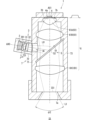
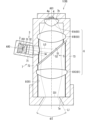
- FIG. 1 is a diagram showing an example of the configuration of the lighting device 1 according to the first embodiment.
- the lighting device 1 is a device that emits fluorescence L1 as illumination light to an external lighting space S1.
- the lighting space S1 is, for example, a space where a person can stay or pass through, and may be, for example, an indoor space of a specific building or a passage space connecting each room.
- the lighting device 1 is disposed, for example, on the ceiling of the lighting space S1.
- the fluorescence L1 emitted from the lighting device 1 can directly illuminate an object in the lighting space S1.
- directly means that the fluorescence L1 is irradiated to the object without passing through optical components such as a lens and a spatial light modulation unit.
- a person in the lighting space S1 can visually recognize the shape and color of the object illuminated by the fluorescence L1.
- the lighting device 1 includes a light source 2, an optical system 3, a wavelength conversion member 4, a wavelength separation filter 5, an optical system 6, and a housing 7.
- a light source 2 As shown in FIG. 1, the lighting device 1 includes a light source 2, an optical system 3, a wavelength conversion member 4, a wavelength separation filter 5, an optical system 6, and a housing 7.
- a wavelength conversion member 4 As shown in FIG. 1, the lighting device 1 includes a light source 2, an optical system 3, a wavelength conversion member 4, a wavelength separation filter 5, an optical system 6, and a housing 7.
- the housing 7 houses the light source 2, the optical system 3, the wavelength conversion member 4, the wavelength separation filter 5, and the optical system 6.
- the housing 7 includes a housing section 71 and a housing section 72.
- the housing section 71 houses the wavelength conversion member 4, the wavelength separation filter 5, and the optical system 6, and the housing section 72 houses the light source 2 and the optical system 3.
- the housing 7 has an exit opening (corresponding to a first opening) 7a.
- the exit opening 7a is formed at the end of the housing part 71. Fluorescence L1 as illumination light is emitted from the exit opening 7a to the illumination space S1.
- the exit opening 7a is a space that connects the internal space of the housing 7 and the illumination space S1.
- the exit opening 7a functions as an outlet for the fluorescence L1 from the internal space of the housing 7 to the illumination space S1.
- a lens does not have to be located inside the exit opening 7a.
- optical components such as a lens and a spatial light modulation unit do not have to be located forward of the exit opening 7a in the emission direction.
- the housing 71 has an elongated shape that is long in the first direction.
- the lighting device 1 is installed on the ceiling, the lighting device 1 is installed on the ceiling with the first direction aligned along the vertical direction.
- the light source 2, the optical system 3, and the wavelength separation filter 5 are aligned along the second direction that intersects with the first direction.
- the housing 72 is attached to the side of the housing 71, and the internal space of the housing 72 and the internal space of the housing 71 are connected to each other through an opening 74 formed in the side of the housing 71.
- the light source 2 emits excitation light L0 into the housing 7.
- the light source 2 has an emission portion (e.g., an emission surface) 201 that emits the excitation light L0.
- the excitation light L0 may be, for example, light having a peak in a wavelength range of 415 nm or less, more specifically, in a wavelength range of 380 nm or more and 415 nm or less.
- the excitation light L0 may be purple light having a peak near 405 nm.
- the excitation light L0 is not necessarily limited to purple light, and may be, for example, blue light having a peak near 450 nm.
- the intensity distribution of the excitation light L0 immediately after the light source 2 has, for example, a mountain-like shape.
- the intensity distribution here refers to the intensity distribution in a cross section perpendicular to the direction of light propagation.
- the intensity distribution of the excitation light L0 immediately after the light source 2 is the intensity distribution of the excitation light L0 in a cross section perpendicular to the optical axis AX0 of the light source 2.
- the intensity distribution of this excitation light L0 has, for example, a mountain-like shape in which the intensity in the center is higher than the intensity in the peripheral area.
- the intensity distribution has a single mountain-like shape with a single peak intensity.
- the intensity distribution of the excitation light L0 in a cross section immediately after the emission part 201 of the light source 2 is shown diagrammatically directly below the light source 2.
- the excitation light L0 from the light source 2 is incident on the wavelength conversion member 4 via the optical system 3, the wavelength separation filter 5, and the lenses 61B and 61A of the optical system 6, as described below.
- the optical system 3 can adjust the intensity distribution of the excitation light L0. Specifically, the optical system 3 flattens the intensity distribution of the excitation light L0.
- the optical system 3 includes an aspherical lens 31.
- the aspherical lens 31 can adjust the intensity distribution of the excitation light L0 by refracting each ray of the excitation light L0. As described in detail later, the aspherical lens 31 refracts each ray of the excitation light L0 so that the intensity distribution of the excitation light L0 on the wavelength conversion member 4 is flattened.
- the intensity distribution of the excitation light L0 on the wavelength conversion member 4 is shown diagrammatically to the right of the wavelength conversion member 4.
- the intensity distribution of the excitation light L0 on the wavelength conversion member 4 has a so-called top hat shape.
- the optical system 3 may further include a cylindrical lens 32.
- the cylindrical lens 32 can adjust the aspect ratio in the intensity distribution of the excitation light L0.
- the cylindrical lens 32 will be described in detail later.
- the excitation light L0 from the optical system 3 passes through the opening 74 and enters the wavelength separation filter 5.
- the wavelength separation filter 5 guides the excitation light L0 to the wavelength conversion member 4.
- the wavelength separation filter 5 reflects the excitation light L0 toward the wavelength conversion member 4 and guides the excitation light L0 to the wavelength conversion member 4.
- the excitation light L0 from the wavelength separation filter 5 enters the wavelength conversion member 4 via lenses 61B and 61A.
- the wavelength conversion member 4 contains a phosphor.
- the wavelength conversion member 4 emits fluorescence L1 based on the incident excitation light L0.
- the fluorescence L1 has a spectrum different from that of the excitation light L0. Specifically, the peak wavelength of the fluorescence L1 is longer than the peak wavelength of the excitation light L0, and the fluorescence L1 is visible light.
- the fluorescence L1 travels from the wavelength conversion member 4 toward the wavelength separation filter 5, and in the example of FIG. 1, it is incident on the wavelength separation filter 5 via lenses 61A and 61B.
- the wavelength separation filter 5 guides the fluorescence L1 to the emission opening 7a. In the example of FIG. 1, the wavelength conversion member 4, the wavelength separation filter 5, and the emission opening 7a are arranged in this order along the first direction, so the wavelength separation filter 5 transmits the fluorescence L1 from the wavelength conversion member 4 to the emission opening 7a side.
- the optical system 6 includes one or more lenses 61 located on the path of the fluorescence L1 between the wavelength conversion member 4 and the exit opening 7a.
- lenses 61A, 61B, and 61C are shown as the lenses 61.
- Lenses 61A to 61C are lined up between the wavelength conversion member 4 and the exit opening 7a.
- lenses 61A and 61B are located between the wavelength conversion member 4 and the wavelength separation filter 5.
- Lens 61A is located closer to the wavelength conversion member 4 than lens 61B.
- Lens 61C is located between the wavelength separation filter 5 and the exit opening 7a. Therefore, in the example of FIG. 1, the wavelength conversion member 4, lens 61A, lens 61B, wavelength separation filter 5, lens 61C, and exit opening 7a are arranged in this order along the first direction.
- the optical system 6 focuses the fluorescence L1 on a virtual image plane IS1 on the side of the exit opening 7a, while emitting it from the exit opening 7a at a predetermined light distribution angle ⁇ 2.
- the light distribution angle ⁇ 2 here is, for example, the spread angle of a portion of the fluorescence L1 that has half the peak intensity.
- the light distribution angle ⁇ 2 can also be called the half-value angle.
- the optical system 6 collects the fluorescence L1 on the side of the exit opening 7a, while emitting it from the exit opening 7a at a predetermined light distribution angle ⁇ 2.
- the optical system 6 forms an image of the fluorescence L1 in the wavelength conversion member 4 on a virtual image plane IS1
- the optical system 6 can also be said to be a so-called imaging optical system.
- the virtual image plane IS1 may be a flat surface or a curved surface. If the image plane IS1 is a curved surface, an inexpensive lens can be used as the lens 61 of the optical system 6.
- the lighting device 1 can emit the fluorescent light L1 into the illumination space S1. Moreover, this lighting device 1 includes an aspherical lens 31.
- the aspherical lens 31 refracts each ray of the excitation light L0 so as to flatten the intensity distribution of the excitation light L0 on the wavelength conversion member 4. Therefore, the excitation light L0 is more uniformly incident on the wavelength conversion member 4.
- the aspherical lens 31 causes excitation light L0 having a more uniform intensity distribution to be incident on the wavelength conversion member 4.
- excitation light L0 having a top-hat shaped intensity distribution is incident on the wavelength conversion member 4. This allows the wavelength conversion member 4 to emit fluorescence L1 more uniformly. Therefore, the lighting device 1 can emit fluorescence L1 into the illumination space S1 with less unevenness, and can realize a high-quality illumination space S1 with less glare.
- the lighting device 1 can emit the fluorescence L1 into the illumination space S1 with higher efficiency.
- the temperature of the central part of the wavelength conversion member 4 becomes high, which is likely to lead to thermal deterioration of the wavelength conversion member 4.
- excitation light L0 which has a lower peak intensity and a more uniform intensity distribution, is incident on the wavelength conversion member 4, so the degree of thermal deterioration of the wavelength conversion member 4 can be reduced.
- the intensity distribution of the excitation light L0 is flattened by the aspherical lens 31, more of the excitation light L0 can be incident on the wavelength conversion member 4.
- the intensity distribution of the excitation light L0 is flattened, but the excitation light L0 is scattered on the surface of the ground glass or at the boundaries between the lenses of the array lens, so the amount of excitation light L0 incident on the wavelength conversion member 4 decreases.
- the aspherical lens 31 can transmit more excitation light L0, so the amount of excitation light L0 incident on the wavelength conversion member 4 can be increased. In other words, the lighting device 1 can emit fluorescence L1 into the illumination space S1 more efficiently.
- the thickness of the aspherical lens 31 is not particularly large, the size of the lighting device 1 can be reduced compared to when a light-guiding member such as a rod lens is used.
- the above description is not intended to prohibit the lighting device 1 of this embodiment from including optical components such as frosted glass, an array lens, and a rod lens in addition to the aspheric lens 31.
- the light source 2 is, for example, a light emitting element such as a semiconductor laser element such as a laser diode (LD), a vertical cavity surface emitting laser (VCSEL), a light emitting diode (LED), and a super luminescent diode (SLD).
- the light source 2 may include a single light emitting element.
- the emission section 201 of the light source 2 may be an emission end of the light emitting element.
- the light emitting element may emit, for example, a 405 nm violet laser light.
- a gallium nitride (GaN) based semiconductor laser that emits the excitation light L0 may be used.
- the light source 2 can emit excitation light L0 having a mountain-shaped intensity distribution.
- the spread angle of the excitation light L0 emitted by the light source 2 on a first axis perpendicular to the optical axis AX0 is larger than the spread angle on a second axis perpendicular to the optical axis AX0 and the first axis (see also FIG. 2).
- the first axis can also be called the fast axis.
- the second axis can also be called the slow axis.
- the spread of the excitation light L0 on the slow axis is shown diagrammatically.
- Wavelength separation filter 5> 1 the wavelength separation filter 5 reflects the excitation light L0 toward the wavelength conversion member 4 and transmits the fluorescence L1 toward the exit opening 7a.
- the wavelength separation filter 5 is also called a dichroic mirror.
- the wavelength separation filter 5 includes, for example, a dielectric multilayer film 51 and a substrate 52.
- the substrate 52 is a transparent plate-like member.
- the substrate 52 is positioned such that its thickness direction intersects with the optical axis AX1 of the optical system 6 at approximately 45 degrees.
- the dielectric multilayer film 51 is formed on the substrate 52.
- the dielectric multilayer film 51 has a structure in which dielectric thin films are repeatedly laminated.
- the dielectric for example, one or more materials selected from silicon oxide (SiO 2 ), titanium oxide (TiO 2 ), aluminum oxide (Al 2 O 3 ), zirconium oxide (ZrO 2 ), tantalum oxide (Ta 2 O 5 ), and niobium oxide (Nb 2 O 3 ) are used.
- SiO 2 silicon oxide
- TiO 2 titanium oxide
- Al 2 O 3 aluminum oxide
- ZrO 2 zirconium oxide
- tantalum oxide Ta 2 O 5
- niobium oxide Nb 2 O 3
- the wavelength conversion member 4 includes a phosphor.
- the wavelength conversion member 4 may include, for example, BaMgAl10O17 :Eu, (Sr,Ca,Ba) 10 ( PO4 ) 6Cl2 :Eu, (Sr,Ba) 10 ( PO4 ) 6Cl2 :Eu , etc. as a wavelength conversion material (i.e., a fluorescent material) that converts the excitation light L0 into blue light.
- the wavelength conversion member 4 may include, for example, (Sr,Ba,Ca) 5 ( PO4 ) 3Cl :Eu , Sr4Al14O25 :Eu, etc.
- the wavelength conversion member 4 may contain, for example, SrSi2 (O,Cl) 2N2 :Eu, (Sr,Ba,Mg) 2SiO4 : Eu2 + , or ZnS:Cu,Al, Zn2SiO4 :Mn, etc. as a wavelength conversion material that converts the excitation light L0 to green light.
- the wavelength conversion member 4 may contain, for example, Y2O2S :Eu, Y2O3 :Eu, SrCaClAlSiN3 : Eu2 + , CaAlSiN3 :Eu, or CaAlSi(ON) 3 :Eu, etc. as a wavelength conversion material that converts the excitation light L0 to red light.
- the wavelength conversion member 4 may contain 3Ga5O12 :Cr, etc. as a wavelength conversion material that converts the excitation light L0 to light having a wavelength in the near - infrared region. If the wavelength conversion member 4 contains multiple types of wavelength converting materials corresponding to multiple colors of light, the wavelength conversion member 4 can emit fluorescence L1 with high color rendering.
- the excitation light L0 is light having a peak at 380 nm to 415 nm and the wavelength conversion member 4 contains phosphors corresponding to red, green, and blue light, the color rendering of the fluorescence L1 can be particularly improved.
- the wavelength conversion member 4 may also contain a resin such as a binder to connect the phosphor particles together.
- the lenses 61 are formed of a material containing at least one of glass, such as optical glass, and resin, such as acrylic resin, for example. As shown in FIG 1, each lens 61 may be a biconvex lens.
- the lens 61 is not limited to a convex lens, but may be a concave lens or a meniscus lens.
- the lens 61 may be a spherical lens or an aspherical lens.
- the optical system 6 forms an image of the object plane on a virtual image plane IS1. That is, in the example of FIG. 1, three lenses 61 can constitute an imaging optical system.
- the surface 4a of the wavelength conversion member 4 has a conjugate relationship with the image plane IS1. Note that the conjugate relationship mentioned here does not have a strict meaning, and the part on the exit opening 7a side where the fluorescence L1 is most concentrated (the part where the size of the fluorescence L1 is smallest in the cross section perpendicular to the optical axis AX1 of the optical system 6) can be considered to be the image plane IS1.
- the image plane IS1 may be located, for example, at the exit opening 7a.
- the fluorescence L1 is collected at the image plane IS1 and is emitted through the exit opening 7a into the illumination space S1.
- the image plane IS1 does not necessarily have to be located inside the exit opening 7a.
- the image plane IS1 may be located slightly offset from the exit opening 7a in the direction of travel of the fluorescence L1 passing through the exit opening 7a. In other words, the image plane IS1 may be located slightly inside the housing 7 relative to the exit opening 7a, or slightly toward the illumination space S1.
- the lens 61A located closest to the wavelength conversion member 4 is a convex lens. Therefore, the lens 61A can guide the fluorescence L1, which has a large divergence angle and is emitted from the wavelength conversion member 4, to the subsequent lens 61B at a smaller divergence angle.
- the lens 61B is also a convex lens. Therefore, the lens 61B can guide the fluorescence L1, which diverges from the lens 61A, to the wavelength separation filter 5 while further reducing the divergence angle.
- the lens 61B may refract the fluorescence L1 so that the fluorescence L1 passes through the wavelength separation filter 5 in a state closer to parallel light.
- the lens 61C focuses the fluorescence L1 that has passed through the wavelength separation filter 5 on the side of the exit opening 7a, and emits it from the exit opening 7a at a predetermined light distribution angle ⁇ 2.
- the optical system 6 reduces the cross-sectional size (e.g., light diameter) of the fluorescence L1 at the image plane IS1, making it less likely for the fluorescence L1 to be reflected or scattered by the inner wall of the exit opening 7a of the housing 7, realizing a more uniform, high-quality illumination space S1 with less glare.
- the presence of the illumination device 1 when viewed from outside the exit opening 7a can be reduced.
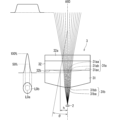
- FIGS. 2 and 3 are diagrams showing an example of the configuration of the optical system 3.
- FIG. 2 shows a configuration of the optical system 3.
- FIG. 3 shows an example of the configuration of the optical system 3 as viewed along the slow axis.
- the aspherical lens 31 is formed of a material including at least one of glass such as optical glass and resin such as acrylic resin.
- the aspherical lens 31 has an aspherical surface 31a and a surface 31b opposite to the aspherical surface 31a.
- the surface 31b is the surface of the aspherical lens 31 facing the light source 2
- the aspherical surface 31a is the surface of the aspherical lens 31 facing the light source 2.
- the aspherical surface 31a has a concave shape.
- the aspherical surface 31a may have a shape that is rotationally symmetric about the optical axis AX0.
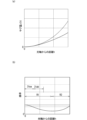
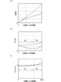
- FIG. 4 is a graph for explaining the shape of the aspheric surface 31a of the aspheric lens 31.
- FIG. 4(a) shows the amount of sag z(h) at each position on the aspheric surface 31a
- FIG. 4(b) shows the curvature at each position on the aspheric surface 31a.
- the horizontal axis shows the distance h from the optical axis AX0.
- the vertical axis shows the amount of sag z(h)
- the vertical axis shows the curvature.
- the graph in FIG. 4(a) shows the relationship between the sag amount z(h) and the distance h, and therefore shows the shape of the aspheric surface 31a itself in a cross section including the optical axis AX0.
- the aspheric surface 31a may have a shape that follows, for example, one of the curves of a hyperbola.
- the aspheric surface 31a may have a shape that follows one of the hyperbolic surfaces of a two-leaf hyperboloid.
- a dashed line is used to show a graph of a sphere having the same curvature as the curvature at the center of the aspheric surface 31a.
- the curvature of a circle is constant regardless of the distance h.
- the curvature in a predetermined circular region R1 including the center of the aspheric surface 31a, gradually decreases as the distance h increases. That is, the curvature monotonically decreases in the circular region R1.
- the predetermined circular region R1 may be, for example, a region that is concentric with the aspheric surface 31a and is about 50% or less of the diameter of the aspheric surface 31a, in other words, a region that is about 50% or less of the effective diameter of the aspheric lens 31.
- the curvature increases slightly and gradually as the distance h increases.
- the curvature has a minimum value at the boundary position between the circular region R1 and the annular region R2.
- the maximum value of the curvature may be more than twice, more than 5 times, more than 10 times, or more than 20 times the minimum value of the curvature.
- Figure 5 is also a graph for explaining the shape of aspheric surface 31a.
- Figure 5(a) is a graph showing the relationship between the angle ⁇ (see also Figures 2 and 3) between the surface normal and the optical axis AX0 at each position within aspheric surface 31a and the distance h.
- Figure 5(b) is a graph showing the relationship between the first-order differential value of angle ⁇ with respect to distance h and the distance h.
- Figure 5(c) is a graph showing the relationship between the second-order differential value of angle ⁇ with respect to distance h and the distance h. Note that, for reference, Figure 5 also shows a graph of a spherical surface having the same curvature as the curvature at the center of aspheric surface 31a by a dashed line.
- the first derivative of the angle ⁇ for the spherical surface increases monotonically with increasing distance h.
- the first derivative of the angle ⁇ for the aspheric surface 31a gradually decreases as the distance h increases, approximately within the circular region R1.
- the first derivative of the angle ⁇ decreases monotonically in the circular region R1.
- the first derivative of the angle ⁇ increases slightly and gradually with increasing distance h, approximately within the annular region R2.
- the maximum value of the first derivative of the angle ⁇ may be at least twice, at least five times, at least ten times, or at least twenty times the minimum value.
- the second derivative of the angle ⁇ for the spherical surface also increases monotonically with increasing distance h.
- the second derivative of the angle ⁇ for the aspheric surface 31a decreases once with increasing distance h, reaches a minimum value (local minimum value), and then increases.
- the graph showing the relationship between the second derivative of the angle ⁇ and the distance h has a local minimum value. More specifically, the graph showing the relationship between the second derivative of the angle ⁇ and the distance h has a local minimum value in a region that is 30% or less of the effective diameter of the aspheric lens 31.
- the second derivative of the angle ⁇ for the spherical surface is positive regardless of the distance h
- the second derivative of the angle ⁇ for the aspheric surface 31a is negative in the entire region that is 30% or less of the effective diameter of the aspheric lens 31.
- excitation light L0 is incident on the aspheric surface 31a of the aspheric lens 31.
- the intensity distribution of the excitation light L0 immediately before it is incident on the aspheric surface 31a is shown typically to the left of the aspheric surface 31a, and the cross-sectional shape of the excitation light L0 is shown typically below the intensity distribution.
- the central light of the excitation light L0 is referred to as central light L0a.
- the central light L0a is a portion of the excitation light L0 whose intensity is, for example, 50% or more of the peak intensity.
- the light of the excitation light L0 that is outside the central light L0a is referred to as peripheral light L0b.
- the peripheral light L0b is a portion of the excitation light L0 whose intensity is, for example, less than 50% of the peak intensity.
- the first central portion 31aa is the portion of the aspheric surface 31a that is closer to the optical axis AX0 than the first non-central portion 31ab.
- the first central portion 31aa is, for example, a region within the circular region R1 (see also FIG. 4(b)). That is, the outer peripheral edge of the first central portion 31aa is, for example, located within the circular region R1.
- the outer peripheral edge of the first central portion 31aa is also the boundary between the first central portion 31aa and the first non-central portion 31ab.
- the first non-central portion 31ab may also be a region within the circular region R1 (see also FIG. 4(b)). That is, the outer peripheral edge of the first non-central portion 31ab may also be located within the circular region R1.
- the curvature at each position of the first central portion 31aa and the first non-central portion 31ab monotonically decreases as it moves from the center to the outside.
- the curvature of the first central portion 31aa is greater than the curvature of the first non-central portion 31ab.
- the average value of the curvature of the first central portion 31aa is greater than the average value of the curvature of the first non-central portion 31ab.
- the minimum value of the curvature of the first central portion 31aa may be greater than the maximum value of the curvature of the first non-central portion 31ab.
- the central light L0a is refracted at the first central portion 31aa with a larger refractive power (see also FIG. 2). Therefore, the spread angle of the central light L0a that passes through the aspherical lens 31 increases. In other words, the central light L0a spreads more as it passes through the aspherical lens 31. Here, the spread angle of the central light L0a increases more as it is closer to the center.
- the curvature of the first non-central portion 31ab is relatively small, the peripheral light L0b is refracted at the first non-central portion 31ab with a smaller refractive power.
- the spread angle of the peripheral light L0b does not increase much compared to the increase in the spread angle of the central light L0a.
- the peripheral light L0b does not spread much as it passes. Therefore, the density of the central light becomes relatively smaller as it moves away from the aspherical lens 31, and the density of the peripheral light becomes relatively larger as it moves away from the aspherical lens 31.
- the width of the central light L0a whose intensity is 50% or more of the peak intensity, becomes relatively wider as it moves away from the aspheric lens 31, and the width of the peripheral light L0b, whose intensity is less than 50% of the peak intensity, becomes relatively narrower. In other words, the intensity distribution becomes flatter.
- the excitation light L0 from the aspherical lens 31 passes through the cylindrical lens 32, the wavelength separation filter 5, the lens 61B, and the lens 61A in this order, and enters the wavelength conversion member 4.
- the shape of the aspherical surface 31a of the aspherical lens 31 can be designed so that the intensity distribution of the excitation light L0 on the surface 4a of the wavelength conversion member 4 has a top hat shape (in other words, a trapezoidal shape).
- Figure 6 is a diagram showing an example of the intensity distribution of the excitation light L0.
- Figure 6(a) shows an example of the intensity distribution of the excitation light L0 immediately after the light source 2.
- Figure 6(a) shows an example of the intensity distribution of the excitation light L0 between the light source 2 and the optical system 3.
- Figure 6(b) shows an example of the intensity distribution of the excitation light L0 in the wavelength conversion member 4. Note that in Figure 6(b), the intensity distribution of the excitation light L0 immediately after the light source 2 is shown by a two-dot chain line.
- the intensity distribution of the excitation light L0 immediately after the light source 2 has a single mountain-shaped shape.
- the width of the region where the intensity is 90% or more of the peak intensity is referred to as the first width D1
- the width of the region where the intensity is 50% or more of the peak intensity is referred to as the second width D2.
- the ratio of the first width D1 to the second width D2 may be, for example, 0.5 or less.
- the intensity distribution of the excitation light L0 in the wavelength conversion member 4 has a top hat shape.
- the intensity distribution has a single trapezoid shape.
- the ratio of the first width D1 to the second width D2 may be 0.7 or more.
- the aspheric lens 31 refracts the excitation light L0 having a ratio of 0.5 or less, thereby causing the excitation light L0 having a ratio of 0.7 or more to be incident on the surface 4a of the wavelength conversion member 4.
- the shape of the aspheric surface 31a may be expressed by the following formula.
- z(h) indicates the amount of sag
- k indicates the Conic coefficient
- R0 indicates the radius of curvature at the center of the aspheric surface 31a
- An (n is an even number) indicates the coefficient of the higher order term.
- FIG. 7 is a graph for explaining the shape of the aspheric surface 31a corresponding to each of a plurality of conic coefficients k.
- FIG. 7(a) is a graph showing the relationship between the sag amount z(h) of the aspheric surface 31a and the distance h
- FIG. 7(b) is a graph showing the relationship between the second derivative of the angle ⁇ and the distance h.
- Graphs Gz1 to Gz7 are shown in FIG. 7(a).
- Graphs Gz1 to Gz7 show the relationship between the sag amount z(h) and the distance h when the conic coefficient k is 0, -1, -5, -10, -20, -40, and -60, respectively.
- Graphs G ⁇ 1 to G ⁇ 7 are shown in FIG. 7(b).
- Graphs G ⁇ 1 to G ⁇ 7 show the relationship between the second derivative of the angle ⁇ and the distance h when the conic coefficient k is 0, -1, -5, -10, -20, -40, and -60, respectively.
- the minimum value of the graph showing the relationship between the second derivative of the angle ⁇ and the distance h is indicated by a hollow circle.
- the smaller the Conic coefficient k the smaller the curvature of the outer periphery of the aspheric surface 31a.
- the curvature of the aspheric surface 31a gradually becomes smaller toward the outer periphery, and in a cross section including the optical axis AX0, the outer periphery of the aspheric surface 31a approaches a straight line shape.
- the outer periphery of the aspheric surface 31a approaches the shape of the side of a cone.
- the curvature of the central part of the aspheric surface 31a does not become much smaller than that of the outer periphery even if the Conic coefficient k becomes smaller.
- the aspheric lens 31 can effectively reduce the increase in the spread angle of the peripheral light L0b of the excitation light L0 while maintaining the effect of increasing the spread angle of the central light L0a of the excitation light L0. As a result, the aspheric lens 31 can more appropriately flatten the intensity distribution of the excitation light L0.
- the Conic coefficient k may be, for example, -60 or more and -3 or less. This allows the aspheric lens 31 to more appropriately flatten the intensity distribution of the excitation light L0 in which the ratio of the first width D1 to the second width D2 is 0.5 or less. Furthermore, the Conic coefficient k may be -60 or more and -10 or less, -60 or more and -20 or less, or -45 or more and -35 or less. The narrower the range that is applied among the above ranges, the more appropriately the aspheric lens 31 can flatten the intensity distribution of the excitation light L0.
- the excitation light L0 is incident on a range of 30% or less of the effective diameter of the aspherical surface 31a of the aspherical lens 31.
- the aspherical lens 31 can further appropriately flatten the intensity distribution.
- the smaller the Conic coefficient k the closer the position of the minimum value is to the center of the aspheric surface 31a. Also, the smaller the Conic coefficient k, the smaller the minimum value. As can be seen from FIG. 7(b), the minimum value may be 30% or less of the effective diameter of the aspheric lens 31, or it may be 25% or less. In this case, the Conic coefficient k is -3 or less.
- the excitation light L0 transmitted through the aspherical lens 31 spreads as it travels towards lens 61B, is refracted by the convex lenses 61B and 61A, and is focused on the wavelength conversion member 4.
- the aspherical surface 31a of the concave aspherical lens 31 can increase the cross-sectional size of the excitation light L0 incident on lens 61B. This allows the excitation light L0 to be incident on the surface 4a of the wavelength conversion member 4 over a sufficiently sized incident area. Therefore, the wavelength conversion member 4 can emit fluorescence L1 over a wider range.
- the surface 31b of the aspherical lens 31 has a convex shape.
- the surface 31b may have a shape that is rotationally symmetric about the optical axis AX0.
- the aspherical surface 31a has a concave shape, and the surface 31b on the opposite side has a convex shape, so that the aspherical lens 31 is a so-called meniscus lens. Since the surface 31b of the aspherical lens 31 has a convex shape, the surface 31b can refract the excitation light L0 so that the spread angle of the excitation light L0 is reduced.
- the concave aspherical surface 31a of the aspherical lens 31 increases the spread angle of the excitation light L0, but the convex surface 31b reduces the spread angle of the excitation light L0. Therefore, the amount of change in the spread angle of the excitation light L0 due to transmission through the aspherical lens 31 can be reduced. This can reduce the possibility that the incidence area of the excitation light L0 will unnecessarily spread on the surface 4a of the wavelength conversion member 4 away from the optical system 3.
- the surface 31b of the aspherical lens 31 may be spherical or aspherical.
- the curvature of the second central portion 31ba of the surface 31b may be greater than the curvature of the second non-central portion 31bb of the surface 31b.
- the curvature of the surface 31b may monotonically decrease from the center toward the outside in a region including both the second central portion 31ba and the second non-central portion 31bb.
- the surface 31b may have a shape along a hyperbolic surface.
- the central light L0a of the excitation light L0 may be incident on the second central portion 31ba
- the peripheral light L0b of the excitation light L0 may be incident on the second non-central portion 31bb.
- the shape of surface 31b may be the same as that of aspheric surface 31a.
- a graph showing the relationship between the second derivative of angle ⁇ and distance h for surface 31b may have a minimum value.
- the minimum value may be located within a region that is 30% or less of the effective diameter of aspheric lens 31.
- the Conic coefficient k may be within the above-mentioned range.
- the central light L0a is refracted at surface 31b so that its spread angle becomes smaller, and the peripheral light L0b is refracted at surface 31b so that its spread angle is not reduced as much as that of the central light L0a. Therefore, the central light L0a can be incident on an area of the aspheric surface 31a with a larger curvature. In other words, since the curvature of the aspheric surface 31a is larger toward the center, the central light L0a is incident on the first central portion 31aa with a larger curvature. Therefore, the aspheric surface 31a can refract the more intense central light L0a at the first central portion 31aa with a larger curvature, and the spread angle of the central light L0a can be made larger. Therefore, the central light L0a of the excitation light L0 can be broadened further, and the intensity distribution can be made flatter.
- Cylindrical lens 32> 1 to 3 the optical system 3 further includes a cylindrical lens 32.
- the cylindrical lens 32 is formed of a material including at least one of glass such as optical glass and resin such as acrylic resin. In the example of FIG. 1, the cylindrical lens 32 is located between the aspheric lens 31 and the wavelength separation filter 5.
- the cylindrical lens 32 adjusts the aspect ratio of the cross-sectional shape of the excitation light L0.
- the cylindrical lens 32 can adjust the ratio between the width of the excitation light L0 on the fast axis and the width of the excitation light L0 on the slow axis.
- the width of the light may be, for example, the width of a region having an intensity equal to or greater than half e of the peak intensity.
- "e” is called the Napier's number.
- the cylindrical lens 32 may adjust the aspect ratio of the excitation light L0, for example, so that the aspect ratio of the cross-sectional shape of the excitation light L0 on the surface 4a of the wavelength conversion member 4 approaches the aspect ratio of the surface 4a of the wavelength conversion member 4.
- the cylindrical lens 32 is a convex-plano lens. That is, the cylindrical lens 32 has a convex surface 32a and a flat surface 32b.
- the flat surface 32b is located on the light source 2 side with respect to the convex surface 32a.
- the flat surface 32b is located on the aspheric lens 31 side with respect to the convex surface 32a.
- the convex surface 32a may be spherical.
- the cylindrical lens 32 is located with its power direction along the fast axis. According to this, in a cross section parallel to the slow axis and the optical axis AX0 (see FIG.
- the spread angle of the excitation light L0 hardly changes before and after the cylindrical lens 32, and in a cross section parallel to the fast axis and the optical axis AX0 (see FIG. 3), the spread angle of the excitation light L0 is reduced by the cylindrical lens 32. Therefore, the difference between the fast axis and the slow axis of the spread angle of the excitation light L0 transmitted through the cylindrical lens 32 can be reduced. Therefore, the aspect ratio of the cross-sectional shape of the excitation light L0 approaches 1 as it moves away from the cylindrical lens 32.
- the aspherical lens 31 and the cylindrical lens 32 may be in contact with each other.
- the outer periphery 31ac of the aspherical surface 31a of the aspherical lens 31 may be a plane perpendicular to the optical axis AX0.
- the outer periphery 31ac may be a portion located outside the first non-central portion 31ab, and may be a portion on which the excitation light L0 is not incident.
- the outer periphery 31ac of the aspherical lens 31 may be in contact with the plane 32b of the cylindrical lens 32, or may be bonded to the plane 32b of the cylindrical lens 32. This makes it easy to position the aspherical lens 31 relative to the cylindrical lens 32.
- the illumination device 1 may include a holder 721 that integrally holds the optical system 3.
- the holder 721 integrally holds the aspherical lens 31 and the cylindrical lens 32, and is attached to the housing 72.
- the holder 721 may, for example, clamp the outer peripheries of the aspherical lens 31 and the cylindrical lens 32 in a direction along the optical axis AX0.
- the holder 721 may be part of the housing part 72.
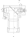
- FIG. 8 is a diagram showing an example of the configuration of the lighting device 1 according to the second embodiment.
- the lighting device 1 according to the second embodiment is referred to as lighting device 1A.
- the lighting device 1A differs from the lighting device 1 according to the first embodiment in terms of the position of the optical element.
- the light source 2, the optical system 3, the wavelength separation filter 5, the lens 61B, the lens 61A, and the wavelength conversion member 4 are arranged in this order in the second direction, and the wavelength separation filter 5 and the exit opening 7a are arranged in this order in the first direction intersecting with the second direction.
- the first direction and the second direction are orthogonal to each other.
- the excitation light L0 from the light source 2 is incident on the optical system 3.
- the optical system 3 adjusts the intensity distribution of the excitation light L0 as described below.
- the excitation light L0 from the optical system 3 is incident on the wavelength separation filter 5.
- the wavelength separation filter 5 transmits the excitation light L0 and guides it to the wavelength conversion member 4.
- the excitation light L0 is transmitted through lenses 61B and 61A of the optical system 6 and is incident on the wavelength conversion member 4.
- the optical system 3 includes an aspherical lens 31.
- the aspherical lens 31 refracts each ray of the excitation light L0 to flatten the intensity distribution of the excitation light L0.
- the aspherical lens 31 refracts the excitation light L0 so that the intensity distribution of the excitation light L0 in the wavelength conversion member 4 has a top hat shape.
- more uniform excitation light L0 is incident on the wavelength conversion member 4, and the wavelength conversion member 4 can emit fluorescence L1 more uniformly.
- the fluorescence L1 from the wavelength conversion member 4 passes through lenses 61A and 61B and enters the wavelength separation filter 5.
- the wavelength separation filter 5 reflects the fluorescence L1 and guides it to the exit opening 7a.
- the optical system 6 is located on the path of the fluorescence L1 from the wavelength conversion member 4 to the exit opening 7a, and emits the fluorescence L1 from the exit opening 7a at a predetermined light distribution angle while forming an image of the fluorescence L1 on a virtual image plane IS1 on the exit opening 7a side.
- the optical system 6 includes one or more lenses 61 located on the path. In the example of FIG. 8, multiple lenses 61 are located, and more specifically, three lenses 61A to 61C are located as the multiple lenses 61. Lenses 61A and 61B are located between the wavelength conversion member 4 and the wavelength separation filter 5. Lens 61A is located on the wavelength conversion member 4 side relative to lens 61B. Lens 61C is located between the wavelength separation filter 5 and the exit opening 7a.
- the aspherical lens 31 flattens the intensity distribution of the excitation light L0. This allows the lighting device 1A to emit fluorescence L1 with less unevenness into the lighting space S1.
- the wavelength conversion member 4, lens 61A, lens 61B, wavelength separation filter 5, optical system 3 and light source 2 are aligned along the second direction, and the wavelength separation filter 5 and lens 61C are aligned in the first direction. This reduces the number of optical components aligned along the first direction, allowing the size of the lighting device 1A in the first direction to be reduced. Therefore, even if the height of the space above the ceiling is low, the lighting device 1A can be easily installed in the space.
- the aspherical lens 31 is a biconvex lens. In other words, both the aspherical surface 31a and the opposite surface 31b of the aspherical lens 31 have a convex shape. In the example of Fig. 8, the aspherical surface 31a is located closer to the light source 2 than the surface 31b. The surface 31b may be spherical.
- FIG. 9 is a diagram for explaining the shape of the aspherical surface 31a of the aspherical lens 31. Note that in the example of FIG. 9, the aspherical surface 31a is located on the opposite side to the light source 2, but even if the aspherical surface 31a is located on the light source 2 side, the principle of flattening the intensity distribution by the aspherical lens 31 is the same.
- the excitation light L0 is refracted at the aspheric surface 31a. Since the aspheric surface 31a has a convex shape, the spread angle of the excitation light L0 is reduced by passing through the aspheric lens 31. In the example of FIG. 9, the excitation light L0 that passes through the aspheric lens 31 narrows as it advances and is focused at the focusing portion BW1. In other words, the excitation light L0 has a focusing portion (i.e., the focusing portion BW1). Then, the excitation light L0 advances while expanding again in front of the focusing portion BW1. Explaining based on FIG.
- the focusing portion BW1 is located between the aspheric lens 31 and the wavelength conversion member 4, and as a more specific example, it is located between the aspheric lens 31 and the lens 61B.
- the focusing portion BW1 may be located between the aspheric lens 31 and the wavelength separation filter 5, may be located on the wavelength separation filter 5, or may be located between the wavelength separation filter 5 and the lens 61B.
- FIG. 10 is a graph for explaining the shape of the aspheric surface 31a of the aspheric lens 31.
- FIG. 10(a) shows the sag amount z(h) at each position on the aspheric surface 31a
- FIG. 10(b) shows the curvature at each position on the aspheric surface 31a.
- FIG. 10 also shows a graph of a spherical surface having the same curvature as the curvature at the center of the aspheric surface 31a by a dashed line.
- the curvature in a predetermined circular region R1 including the center of the aspherical surface 31a, gradually decreases as the distance h increases. That is, the curvature monotonically decreases in the circular region R1.
- the diameter of the circular region R1 is about 60% of the effective diameter of the aspherical lens 31.
- the curvature gradually increases as the distance h increases in the annular region R2 located outside the circular region R1 of the aspherical surface 31a. That is, the curvature has a minimum value at the boundary position between the circular region R1 and the annular region R2.
- the maximum value of the curvature may be more than twice the minimum value of the curvature.
- FIG. 11 is also a graph for explaining the shape of aspheric surface 31a.
- FIG. 11(a) is a graph showing the relationship between angle ⁇ and distance h.
- FIG. 11(b) is a graph showing the relationship between the first derivative of angle ⁇ with respect to distance h and distance h.
- FIG. 11(c) is a graph showing the relationship between the second derivative of angle ⁇ with respect to distance h and distance h.
- the dashed line also shows a graph for a spherical surface having the same curvature as the curvature at the center of aspheric surface 31a.
- the first derivative of the angle ⁇ for the spherical surface increases monotonically with increasing distance h.
- the first derivative of the angle ⁇ for the aspheric surface 31a gradually decreases as the distance h increases, approximately within the circular region R1.
- the first derivative of the angle ⁇ decreases monotonically in the circular region R1.
- the first derivative of the angle ⁇ gradually increases slightly with increasing distance h, approximately within the annular region R2.
- the maximum value of the first derivative of the angle ⁇ may be more than twice the minimum value of the curvature.
- the second derivative of the angle ⁇ for the spherical surface also increases monotonically with increasing distance h.
- the second derivative of the angle ⁇ for the aspheric surface 31a decreases once with increasing distance h, reaches a minimum value (local minimum value), and then increases.
- the graph showing the relationship between the second derivative of the angle ⁇ and the distance h has a local minimum value. More specifically, the graph showing the relationship between the second derivative of the angle ⁇ and the distance h has a local minimum value in a region that is 30% or less of the effective diameter of the aspheric lens 31.
- the second derivative of the angle ⁇ for the spherical surface is positive regardless of the distance h, the second derivative of the angle ⁇ is negative in the entire region that is 30% or less of the effective diameter of the aspheric lens 31.
- excitation light L0 is incident on the aspheric surface 31a of the aspheric lens 31.
- the intensity distribution of the excitation light L0 immediately before it is incident on the aspheric surface 31a is shown diagrammatically below the aspheric lens 31, and the cross-sectional shape of the excitation light L0 is shown diagrammatically to the right of the intensity distribution.
- the central light L0a is incident on the first central portion 31aa of the aspheric surface 31a
- the peripheral light L0b is incident on the first non-central portion 31ab of the aspheric surface 31a.
- the first central portion 31aa is, for example, a region within the circular region R1 (see also FIG. 10(b)). That is, the outer peripheral edge of the first central portion 31aa is, for example, located within the circular region R1.
- the first non-central portion 31ab may also be a region within the circular region R1 (see also FIG. 10(b)). That is, the outer peripheral edge of the first non-central portion 31ab may also be located within the circular region R1.
- the curvature at each position on the first central portion 31aa and the first non-central portion 31ab monotonically decreases as it moves from the center to the outside.
- the curvature of the first central portion 31aa is greater than the curvature of the first non-central portion 31ab.
- the average value of the curvature of the first central portion 31aa is greater than the average value of the curvature of the first non-central portion 31ab.
- the minimum value of the curvature of the first central portion 31aa may be greater than the maximum value of the curvature of the first non-central portion 31ab.
- the central light L0a is refracted with a greater refractive power. Therefore, the central light L0a is focused at a position closer to the aspherical lens 31 and travels while spreading out forward of the focusing position.
- the closer to the center the light ray of the central light L0a is, the greater the refractive power it is refracted with. Therefore, the closer to the center the light ray is, the closer to the center it is focused at a position closer to the aspherical lens 31.
- the two central light rays that are focused at the position closest to the aspherical lens 31 are shown by dashed lines.
- the peripheral light L0b is refracted with a smaller refractive power.
- the peripheral light L0b is focused at a position farther from the aspherical lens 31 and advances while spreading out forward from the focusing position.
- the light rays of the peripheral light L0b closer to the outer periphery are refracted with a smaller refractive power.
- the light rays closer to the outer periphery are focused at a position farther from the aspherical lens 31.
- the two peripheral light rays that are focused at the position farthest from the aspherical lens 31 are shown by dashed lines.
- the density of the light beams closer to the center decreases at a position forward of the focusing part BW1. Conversely, the density of the light beams closer to the periphery increases. In other words, the width of the central light L0a, whose intensity is 50% or more of the peak intensity, becomes relatively wider as it moves forward from the focusing part BW1, and the width of the peripheral light L0b, whose intensity is less than 50% of the peak intensity, becomes relatively narrower. Therefore, the intensity distribution becomes flatter.
- the excitation light L0 from the aspherical lens 31 passes through the wavelength separation filter 5, lens 61B, and lens 61A in that order, and enters the wavelength conversion member 4.
- the shape of the aspherical surface 31a of the aspherical lens 31 can be designed so that the intensity distribution of the excitation light L0 on the surface 4a of the wavelength conversion member 4 has a top hat shape.
- the Conic coefficient k which is one of the indices that indicate the shape of the aspheric surface 31a of the aspheric lens 31, may be -60 or more and -3 or less, as in the first embodiment. This allows the aspheric lens 31 to more appropriately flatten the intensity distribution of the excitation light L0 in which the ratio of the first width D1 to the second width D2 is 0.5 or less. Furthermore, the Conic coefficient k may be -60 or more and -10 or less, -60 or more and -20 or less, or -45 or more and -35 or less.
- the excitation light L0 advances while spreading out in front of the focusing section BW1. Therefore, the excitation light L0 can be sufficiently spread out just before the lens 61B, and even if the excitation light L0 is reduced in size by the convex lenses 61A and 61B, it can be incident on the surface 4a of the wavelength conversion member 4 over a sufficiently large incident area.
- the aspherical lens 31 focuses the excitation light L0 at the focusing portion BW1, and therefore has a large refractive power.
- the radius of curvature R0 at the center of the aspherical surface 31a is larger than the radius of curvature R0 of the aspherical surface 31a according to the first embodiment.
- the cylindrical lens 32 is positioned between the light source 2 and the aspherical lens 31.
- the cylindrical lens 32 refracts the excitation light L0 so that the aspect ratio of the excitation light L0 approaches 1.
- the aspect ratio of the excitation light L0 immediately after the cylindrical lens 32 is closer to 1 than the aspect ratio of the excitation light L0 immediately before the cylindrical lens 32. Therefore, the excitation light L0 can be made to enter the aspherical lens 31 with the difference between the fast axis width and the slow axis width of the excitation light L0 reduced.
- the aspect ratio of the cross-sectional shape of the excitation light L0 entering the aspherical lens 31 is close to 1.
- the aspheric lens 31 can more appropriately flatten the intensity distribution on both the fast axis and the slow axis.
- FIG. 12 is a diagram for explaining another example of the aspherical surface 31a of the aspherical lens 31.
- the aspherical surface 31a also has a convex shape, so the spread angle of the excitation light L0 is reduced by transmission through the aspherical lens 31.
- the excitation light L0 transmitted through the aspherical lens 31 advances while narrowing.
- the excitation light L0 is incident on the surface 4a of the wavelength conversion member 4 before the focusing part where the light diameter is smallest.
- the excitation light L0 does not have the focusing part BW1 between the aspherical lens 31 and the wavelength conversion member 4.
- the curvature of the first central portion 31aa of the aspheric surface 31a is smaller than the curvature of the first non-central portion 31ab.
- the curvature of the aspheric surface 31a may monotonically increase from the center toward the outside in the region including the first central portion 31aa and the first non-central portion 31ab.
- the central light L0a is refracted with a smaller refractive power.
- the central light L0a is focused at a position farther from the aspherical lens 31.
- the closer to the center a ray of light is, the farther from the aspherical lens 31 it is focused at.
- the two central light rays that are focused at the position farthest from the aspherical lens 31 are shown by dashed lines, and the virtual focusing position Pa of the two light rays is shown diagrammatically.
- the peripheral light L0b is refracted with a greater refractive power.
- the peripheral light L0b is focused at a position closer to the aspherical lens 31.
- the closer a ray of the peripheral light L0b is to the periphery the greater the refractive power it is refracted with.
- the closer a ray is to the periphery the closer it is to the aspherical lens 31 it is focused at a position closer to the aspherical lens 31.
- the two peripheral light rays that are focused at the position closest to the aspherical lens 31 are shown by dashed lines, and the virtual focusing position Pb of the two light rays is shown diagrammatically.
- the density of light rays closer to the center is relatively small between the aspherical lens 31 and the focusing position Pb.
- the density of light rays closer to the periphery is high.
- the width of the central light L0a whose intensity is 50% or more of the peak intensity, becomes relatively wider toward the front of the aspherical lens 31, and the width of the peripheral light L0b, whose intensity is less than 50% of the peak intensity, becomes relatively narrower. Therefore, the intensity distribution becomes flatter.
- the excitation light L0 from the aspherical lens 31 passes through the wavelength separation filter 5, lens 61B, and lens 61A in that order, and enters the wavelength conversion member 4.
- the shape of the aspherical surface 31a of the aspherical lens 31 can be designed so that the intensity distribution of the excitation light L0 on the surface 4a of the wavelength conversion member 4 has a top hat shape.
- shape of the aspherical surface 31a of the aspherical lens 31 in the second embodiment can be applied to the first embodiment, and the shape of the aspherical surface 31a of the aspherical lens 31 in the first embodiment can be applied to the second embodiment.
- FIG. 13 is a diagram showing an example of the configuration of the illumination device 1 according to the third embodiment.
- the illumination device 1 in FIG. 13 is referred to as illumination device 1B.
- the illumination device 1B differs from the illumination device 1 according to the first embodiment in the presence or absence of a light reducing structure 8.
- the light reducing structure 8 is located on at least a part of the inner wall of the housing 7. More specifically, the light reducing structure 8 is located on at least a part of the inner wall of the housing part 71.
- the housing part 71 includes a cylindrical part 73 surrounding the path of the fluorescence L1.
- the cylindrical part 73 houses the lens 61A, the lens 61B, the wavelength separation filter 5, and the lens 61C.
- An exit opening 7a is formed at the end of the cylindrical part 73.
- an opening 74 is formed on the side of the cylindrical part 73 for the excitation light L0 from the light source 2 to pass through.
- the light reducing structure 8 is located on at least a part of the inner wall of the cylindrical portion 73, and as a more specific example, it is located on the inner wall of the cylindrical portion 73 between the lens 61B and the wavelength separation filter 5, between the wavelength separation filter 5 and the lens 61C, and between the lens 61C and the exit opening 7a.
- the light reducing structure 8 does not have to be located between the lens 61A and the lens 61B on the inner wall of the cylindrical portion 73.
- the light reducing structure 8 may be formed on the entire circumference of the inner wall of the cylindrical portion 73.
- the "entire circumference" here refers to the entire circumference of the inner wall in a cross section perpendicular to the optical axis AX1.
- the light reduction structure 8 reduces the possibility that the unwanted light will be emitted from the emission opening 7a into the illumination space S1.
- the light reduction structure 8 includes, for example, a reflection reduction section 81.
- the reflection reduction section 81 may include an absorbing film having a high absorptivity for the fluorescence L1.
- the absorptivity may be, for example, 50% or more, 60% or more, 80% or more, or 90% or more.
- the reflection reduction section 81 may have a high absorptivity for the entire wavelength range of the fluorescence L1, or may have a high absorptivity for the peak wavelength.
- the absorptivity of the reflection reduction section 81 for the fluorescence L1 is higher than the absorptivity of the inner wall of the housing section 71 where the light reduction structure 8 is not located.
- Such a reflection reduction section 81 can be formed, for example, by performing a blackening process on the inner wall of the housing section 71.
- the reflection reduction section 81 is formed on the inner wall of the housing section 71 by a blackening process such as chemical conversion treatment, plating, and painting.
- a blackening process such as chemical conversion treatment, plating, and painting.
- a matte blackening process or a glossy blackening process may be adopted.
- Such a reflection reduction section 81 is made of a black material.
- the material includes, for example, at least one of a black metal, a black metal oxide film, and a black resin.
- the reflection reduction portion 81 may include a dielectric multilayer film.
- the dielectric multilayer film has, for example, a structure in which a plurality of dielectric thin films are stacked.
- the dielectric for example, one or more materials selected from titanium oxide (TiO 2 ), SiO 2 , niobium pentoxide (Nb 2 O 5 ), tantalum pentoxide (Ta 2 O 5 ), and magnesium fluoride (MgF 2 ) are used.
- Such a dielectric multilayer film may also be called a low reflection film or an anti-reflection film.
- the reflection reduction section 81 may include flocked paper.
- the flocked paper may be composed of a base material such as paper or cloth, and synthetic fibers attached in an upright position to the base material. If black flocked paper is used, it is possible to further reduce the reflection of unwanted light compared to flocked paper of other colors.
- lighting device 1B for example, when unwanted light obtained by reflection and scattering of fluorescence L1 in the optical system 6 travels toward the reflection reduction section 81 on the inner wall of the cylindrical section 73, it is incident on the reflection reduction section 81. Since the reflection reduction section 81 reduces the reflection of unwanted light, it is possible to reduce the unwanted light that is emitted from the emission opening 7a. Therefore, lighting device 1B can emit high-quality fluorescence L1 with even less unevenness into the illumination space S1.
- FIG. 14 is an enlarged view showing a schematic portion of another example of the light reduction structure 8.
- the light reduction structure 8 includes an uneven shape 82.
- the uneven shape 82 is, for example, the shape of the inner wall surface of the cylindrical portion 73, and FIG. 14 shows a schematic portion of the uneven shape 82.
- the uneven shape 82 has unevenness in the optical axis direction parallel to the optical axis AX1.
- the uneven shape 82 has a shape in which concave and convex portions are arranged alternately in a cross section including the optical axis AX1.
- the uneven shape 82 has a sawtooth shape, and each tooth of the sawtooth (i.e., the convex portion) is formed by a first surface 821 on the wavelength conversion member 4 side and a second surface 822 on the emission opening 7a side.
- the first surfaces 821 and the second surfaces 822 are alternately continuous.
- Such an uneven shape 82 may have a helical shape similar to a female screw, or may have a shape in which multiple ring shapes are arranged in the optical axis direction.
- the pitch of the uneven shape 82 is set to, for example, about several mm or less.
- the length of the second surface 822 which moves away from the optical axis AX1 toward the exit opening 7a, may be longer than that of the first surface 821.
- the angle that the second surface 822 makes with respect to the optical axis AX1 may be smaller than the angle that the first surface 821 makes with respect to the optical axis AX1.
- the first surface 821 is nearly perpendicular to the optical axis AX1, so that in a cross section including the optical axis AX1, the first surface 821 corresponds to the adjacent side of a right triangle and corresponds to the hypotenuse of the right triangle of the second surface 822.
- Unwanted light is incident on the inner wall surface of the cylindrical section 73 in an oblique direction, mainly from the wavelength conversion member 4 side.
- the first surface 821 reflects and scatters the incident unwanted light mainly toward the opposite side to the emission opening 7a. In other words, the first surface 821 reflects and scatters the unwanted light mainly in an oblique direction toward the wavelength conversion member 4 side.
- some of the unwanted light from the first surface 821 may be incident on the second surface 822, since the second surface 822 is inclined, most of the unwanted light can be reflected and scattered in an oblique direction toward the wavelength conversion member 4 side.
- the unwanted light reflected and scattered by the second surface 822 is incident on the first surface 821, where it is reflected and scattered in an oblique direction toward the wavelength conversion member 4 side.
- the unwanted light that is incident on the uneven shape 82 from the wavelength conversion member 4 side can be mainly reflected and scattered in an oblique direction toward the wavelength conversion member 4 side. This increases the number of times the unwanted light is reflected and scattered within the housing 7, and the unwanted light can be attenuated within the housing 7. Therefore, the possibility of unwanted light being emitted from the exit opening 7a can be reduced.
- FIG. 15 is a diagram showing a schematic diagram of another example of the configuration of the lighting device 1 according to the third embodiment.
- the lighting device 1 in FIG. 15 is referred to as lighting device 1C.
- the lighting device 1C differs from the lighting device 1A in the presence or absence of a light reduction structure 8.
- the light reduction structure 8 is located on at least a part of the inner wall of the housing 7. More specifically, the light reduction structure 8 is located on at least a part of the inner wall of the housing part 71.
- the housing part 71 includes a cylindrical part 711 that houses the lens 61A and the lens 61B, a connecting part 712 that houses the wavelength separation filter 5, and a cylindrical part 713 that houses the lens 61C.
- An emission opening 7a is formed at the end of the cylindrical part 713 opposite the connecting part 712.
- the light reduction structure 8 is located on at least a part of the inner walls of the cylindrical portion 711 and the cylindrical portion 713.
- the light reduction structure 8 is located on the inner wall of the cylindrical portion 711 between the lens 61B and the wavelength separation filter 5, on the inner wall of the cylindrical portion 713 between the wavelength separation filter 5 and the lens 61C, and between the lens 61C and the exit opening 7a.
- the light reduction structure 8 does not have to be located between the lens 61A and the lens 61B on the inner wall of the cylindrical portion 711.
- the light reduction structure 8 may be formed on the entire circumference of the inner walls of the cylindrical portion 711 and the cylindrical portion 713.
- a reflection reduction portion 81 or an uneven shape 82 may be applied to the light reduction structure 8.
- this lighting device 1C can also reduce the possibility of unwanted light being emitted from the exit opening 7a.
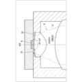
- FIG. 16 is an enlarged view of a portion of the configuration of the illumination device 1.
- an opening 70 is located between the wavelength conversion member 4 and the optical system 6 in the path of the fluorescence L1.
- the opening 70 has a second opening (hereinafter referred to as the diaphragm opening) 7b.
- the diaphragm opening 7b of the opening 70 passes the light of the fluorescence L1 having a divergence angle of a predetermined divergence angle ⁇ 1 or less to the optical system 6 side.
- the shielded light light that travels at a divergence angle larger than the divergence angle ⁇ 1 of the fluorescence L1 is blocked by the opening 70.
- the opening 70 may be a part of the housing 7.
- the surface area of the wavelength conversion member 4 as viewed along the optical axis direction parallel to the optical axis AX1 may be smaller than the minimum opening area of the aperture 7b of the opening 70. This allows a larger portion of the fluorescence L1 that spreads out and travels from the wavelength conversion member 4 to pass through the aperture 7b.
- the angle ⁇ 1 that defines the numerical aperture of the optical system 6 may be equal to or greater than the spread angle ⁇ 1 of the fluorescence L1 that passes through the diaphragm aperture 7b.
- the numerical aperture is the product of the sine of the half-value of the angle ⁇ 1 and the refractive index.
- the angle ⁇ 1 is, for example, the angle formed by both outer rays of virtual light that can pass through the effective area of the optical system 6.
- the effective area here corresponds to the area through which light passes through which the optical performance of the optical system 6 can be exhibited, and for example, the effective area of the lens 61A is the area of the lens 61A excluding a predetermined peripheral width.
- the effective area of the lens 61A may be the area surrounded by the inner peripheral edge of the part of the housing 7 that holds the peripheral edge of the lens 61A (for example, the lens holder).
- the spread angle ⁇ 1 and the angle ⁇ 1 are equal to each other.
- the lighting device 1 can emit high-quality fluorescence L1 with even less glare into the lighting space S1.
- the lighting devices 1, 1A to 1C have been described in detail, but the above description is merely an example in all respects, and the lighting devices 1, 1A to 1C are not limited thereto. It is understood that countless variations not illustrated can be imagined without departing from the scope of this disclosure.
- the configurations described in the above embodiments and variations (or aspects) can be combined or omitted as appropriate, as long as they are not mutually contradictory.
- lenses such as lens 61A and lens 61B may not be positioned between the wavelength conversion member 4 and the wavelength separation filter 5.
- aspheric lens 31 may be positioned between the wavelength conversion member 4 and the wavelength separation filter 5.
- fluorescence L1 from the wavelength conversion member 4 passes through the aspheric lens 31 and enters the wavelength separation filter 5.
- the wavelength separation filter 5 does not necessarily have to be a dichroic mirror.
- the wavelength separation filter 5 may be a dichroic prism.
- This disclosure includes the following:
- the lighting device is a lighting device that emits illumination light into an external illumination space, and can include a housing having a first opening that opens into the illumination space, a light source that emits excitation light into the interior of the housing, an aspherical lens located inside the housing, into which the excitation light from the light source is incident and that flattens the intensity distribution of the excitation light, a wavelength conversion member located inside the housing, into which the excitation light from the aspherical lens is incident and that emits fluorescence as the illumination light having a spectrum different from that of the excitation light based on the excitation light, and a wavelength separation filter located inside the housing, which guides the excitation light from the aspherical lens to the wavelength conversion member and guides the fluorescence from the wavelength conversion member to the first opening.
- the aspherical surface of the aspherical lens may have a concave shape, and the curvature of a first central portion of the aspherical surface on the central side may be greater than the curvature of a first non-central portion of the aspherical surface that is located outside the first central portion.
- the surface of the aspherical lens opposite the aspherical surface may have a convex shape.
- the curvature of a second central portion of the opposite surface of the aspheric lens may be greater than the curvature of a second non-central portion of the opposite surface that is located outside the second central portion.
- the aspherical surface of the aspherical lens may have a convex shape, and the curvature of a first central portion of the aspherical surface may be smaller than the curvature of a first non-central portion of the aspherical surface that is located outside the first central portion.
- the aspherical surface of the aspherical lens may have a convex shape, the curvature of a first central portion of the aspherical surface may be greater than the curvature of a first non-central portion of the aspherical surface that is located outside the first central portion, and the excitation light from the aspherical lens may have a portion that is focused between the aspherical lens and the wavelength conversion member.
- a central light having an intensity of 50% or more of the peak intensity can be incident on the first central portion of the aspherical lens, and peripheral light on the outer periphery side of the central light can be incident on the first non-central portion of the aspherical lens.
- a graph showing the relationship between the second derivative of the angle between the surface normal at a position on the aspheric surface of the aspheric lens and the optical axis of the aspheric lens with respect to the distance between the optical axis and the position and the distance can have a minimum value.
- the graph can have the minimum value at least in a region that is 30% or less of the effective diameter of the aspherical lens.
- the Conic coefficient indicating the aspheric shape of the aspheric lens may be greater than or equal to -60 and less than or equal to -3.
- the ratio of a first width of a region having an intensity of 50% or more of the peak intensity to a second width of a region having an intensity of 90% or more of the peak intensity may be 0.7 or more.
- any one of the illumination devices (1) to (11) above may further include a cylindrical lens positioned between the light source and the wavelength separation filter to adjust the aspect ratio of the cross-sectional shape of the excitation light.
- the cylindrical lens can be positioned between the light source and the aspherical lens.
- the lighting device of (12) or (13) above may further include a holder that holds the cylindrical lens and the aspherical lens together.
- the peak wavelength of the excitation light may be 415 nm or less, and the wavelength conversion member may include multiple types of phosphors.
- the light source may include a semiconductor laser element.
- a light reducing structure may be located on the inner wall of the housing to absorb unwanted light generated by reflection or scattering of the fluorescence, or to reflect or scatter the unwanted light toward the wavelength conversion member.
- any one of the lighting devices (1) to (17) above may include an optical system that is located on the path of the fluorescence from the wavelength conversion member to the first opening and that focuses the fluorescence on a virtual image plane on the first opening side.
- the lighting device of (18) above may further include an opening having a second opening that passes the fluorescence from the wavelength conversion member with a predetermined spread angle or less toward the optical system and blocks the fluorescence with a larger spread angle than the predetermined spread angle, and the angle that defines the numerical aperture of the optical system may be equal to or greater than the predetermined spread angle.
- the optical system includes a plurality of lenses positioned on the path.
Landscapes
- Engineering & Computer Science (AREA)
- General Engineering & Computer Science (AREA)
- Physics & Mathematics (AREA)
- Spectroscopy & Molecular Physics (AREA)
- Lenses (AREA)
Priority Applications (1)
| Application Number | Priority Date | Filing Date | Title |
|---|---|---|---|
| JP2024551424A JPWO2024084935A1 (https=) | 2022-10-20 | 2023-10-02 |
Applications Claiming Priority (2)
| Application Number | Priority Date | Filing Date | Title |
|---|---|---|---|
| JP2022-168283 | 2022-10-20 | ||
| JP2022168283 | 2022-10-20 |
Publications (1)
| Publication Number | Publication Date |
|---|---|
| WO2024084935A1 true WO2024084935A1 (ja) | 2024-04-25 |
Family
ID=90737303
Family Applications (1)
| Application Number | Title | Priority Date | Filing Date |
|---|---|---|---|
| PCT/JP2023/035871 Ceased WO2024084935A1 (ja) | 2022-10-20 | 2023-10-02 | 照明装置 |
Country Status (2)
| Country | Link |
|---|---|
| JP (1) | JPWO2024084935A1 (https=) |
| WO (1) | WO2024084935A1 (https=) |
Cited By (1)
| Publication number | Priority date | Publication date | Assignee | Title |
|---|---|---|---|---|
| US12379093B2 (en) * | 2021-06-30 | 2025-08-05 | Kyocera Corporation | Illumination apparatus |
Citations (5)
| Publication number | Priority date | Publication date | Assignee | Title |
|---|---|---|---|---|
| JP2020118947A (ja) * | 2018-06-19 | 2020-08-06 | カシオ計算機株式会社 | 光源装置及び投影装置 |
| JP2020154032A (ja) * | 2019-03-18 | 2020-09-24 | セイコーエプソン株式会社 | 波長変換素子、光源装置、プロジェクター、及び波長変換素子の製造方法 |
| JP2021086135A (ja) * | 2019-11-29 | 2021-06-03 | 株式会社リコー | 光源光学系、光源装置及び画像表示装置 |
| JP2021125365A (ja) * | 2020-02-05 | 2021-08-30 | ウシオ電機株式会社 | 光源ユニット、その光源ユニットを備えるファイバ光源装置 |
| JP2022038680A (ja) * | 2020-08-27 | 2022-03-10 | セイコーエプソン株式会社 | 照明装置およびプロジェクター |
-
2023
- 2023-10-02 WO PCT/JP2023/035871 patent/WO2024084935A1/ja not_active Ceased
- 2023-10-02 JP JP2024551424A patent/JPWO2024084935A1/ja active Pending
Patent Citations (5)
| Publication number | Priority date | Publication date | Assignee | Title |
|---|---|---|---|---|
| JP2020118947A (ja) * | 2018-06-19 | 2020-08-06 | カシオ計算機株式会社 | 光源装置及び投影装置 |
| JP2020154032A (ja) * | 2019-03-18 | 2020-09-24 | セイコーエプソン株式会社 | 波長変換素子、光源装置、プロジェクター、及び波長変換素子の製造方法 |
| JP2021086135A (ja) * | 2019-11-29 | 2021-06-03 | 株式会社リコー | 光源光学系、光源装置及び画像表示装置 |
| JP2021125365A (ja) * | 2020-02-05 | 2021-08-30 | ウシオ電機株式会社 | 光源ユニット、その光源ユニットを備えるファイバ光源装置 |
| JP2022038680A (ja) * | 2020-08-27 | 2022-03-10 | セイコーエプソン株式会社 | 照明装置およびプロジェクター |
Cited By (1)
| Publication number | Priority date | Publication date | Assignee | Title |
|---|---|---|---|---|
| US12379093B2 (en) * | 2021-06-30 | 2025-08-05 | Kyocera Corporation | Illumination apparatus |
Also Published As
| Publication number | Publication date |
|---|---|
| JPWO2024084935A1 (https=) | 2024-04-25 |
Similar Documents
| Publication | Publication Date | Title |
|---|---|---|
| US10750070B2 (en) | Light-emitting diode and surveillance camera device using the same | |
| WO2024084935A1 (ja) | 照明装置 | |
| US20140098541A1 (en) | Lighting apparatus | |
| TW200918829A (en) | Light output device | |
| JP7710518B2 (ja) | 照明装置 | |
| EP3593179B1 (en) | A collimator and a lighting unit | |
| CN103672501A (zh) | 光源 | |
| TW201903354A (zh) | 光源裝置以及具備該裝置的測距感測器 | |
| JPWO2023276854A5 (https=) | ||
| US9904045B2 (en) | Integrating cone for an illumination device | |
| JP2024060779A (ja) | 照明装置 | |
| US9784899B2 (en) | LED illumination apparatus | |
| KR100342724B1 (ko) | 오버헤드프로젝션용이중그루브프레넬렌즈 | |
| JP7150216B1 (ja) | 照明装置 | |
| JPWO2024084935A5 (https=) | ||
| WO2023276257A1 (ja) | 照明装置 | |
| JP2026039617A (ja) | 照明装置 | |
| CN203585861U (zh) | 光源 | |
| CN101720444A (zh) | 透镜系统 | |
| WO2024009996A1 (ja) | 照明装置 | |
| JP2024033140A (ja) | 照明装置 | |
| WO2024177114A1 (ja) | 照明装置 | |
| JP7414967B2 (ja) | 光変換装置および照明システム | |
| WO2023276256A1 (ja) | 照明装置 | |
| JPH08327908A (ja) | 照明光学系 |
Legal Events
| Date | Code | Title | Description |
|---|---|---|---|
| 121 | Ep: the epo has been informed by wipo that ep was designated in this application |
Ref document number: 23879582 Country of ref document: EP Kind code of ref document: A1 |
|
| WWE | Wipo information: entry into national phase |
Ref document number: 2024551424 Country of ref document: JP |
|
| NENP | Non-entry into the national phase |
Ref country code: DE |
|
| 122 | Ep: pct application non-entry in european phase |
Ref document number: 23879582 Country of ref document: EP Kind code of ref document: A1 |