WO2024009996A1 - 照明装置 - Google Patents
照明装置 Download PDFInfo
- Publication number
- WO2024009996A1 WO2024009996A1 PCT/JP2023/024758 JP2023024758W WO2024009996A1 WO 2024009996 A1 WO2024009996 A1 WO 2024009996A1 JP 2023024758 W JP2023024758 W JP 2023024758W WO 2024009996 A1 WO2024009996 A1 WO 2024009996A1
- Authority
- WO
- WIPO (PCT)
- Prior art keywords
- lens
- separation filter
- wavelength conversion
- conversion member
- wavelength
- Prior art date
Links
- 238000000926 separation method Methods 0.000 claims abstract description 217
- 238000006243 chemical reaction Methods 0.000 claims abstract description 211
- 230000003287 optical effect Effects 0.000 claims abstract description 174
- 230000005284 excitation Effects 0.000 claims abstract description 113
- 238000001228 spectrum Methods 0.000 claims abstract description 5
- 230000002093 peripheral effect Effects 0.000 claims description 74
- 238000005286 illumination Methods 0.000 claims description 59
- 238000013459 approach Methods 0.000 claims description 12
- 238000003384 imaging method Methods 0.000 claims description 9
- 238000003825 pressing Methods 0.000 claims description 7
- 230000000903 blocking effect Effects 0.000 claims 1
- 239000010408 film Substances 0.000 description 35
- 239000000463 material Substances 0.000 description 24
- 230000003595 spectral effect Effects 0.000 description 24
- 238000002834 transmittance Methods 0.000 description 22
- 238000003860 storage Methods 0.000 description 9
- 238000010521 absorption reaction Methods 0.000 description 7
- 238000010586 diagram Methods 0.000 description 7
- 238000011282 treatment Methods 0.000 description 6
- OAICVXFJPJFONN-UHFFFAOYSA-N Phosphorus Chemical compound [P] OAICVXFJPJFONN-UHFFFAOYSA-N 0.000 description 5
- 230000004313 glare Effects 0.000 description 5
- 239000011347 resin Substances 0.000 description 5
- 229920005989 resin Polymers 0.000 description 5
- 239000000853 adhesive Substances 0.000 description 4
- 230000001070 adhesive effect Effects 0.000 description 4
- 229910052788 barium Inorganic materials 0.000 description 4
- 239000011651 chromium Substances 0.000 description 4
- 239000000835 fiber Substances 0.000 description 4
- 239000011777 magnesium Substances 0.000 description 4
- 239000007769 metal material Substances 0.000 description 4
- 230000010287 polarization Effects 0.000 description 4
- 229910052712 strontium Inorganic materials 0.000 description 4
- 239000004925 Acrylic resin Substances 0.000 description 3
- 229920000178 Acrylic resin Polymers 0.000 description 3
- 229910052782 aluminium Inorganic materials 0.000 description 3
- 238000005253 cladding Methods 0.000 description 3
- 239000010949 copper Substances 0.000 description 3
- 238000013461 design Methods 0.000 description 3
- 239000011521 glass Substances 0.000 description 3
- 229910052749 magnesium Inorganic materials 0.000 description 3
- 238000000034 method Methods 0.000 description 3
- 239000005304 optical glass Substances 0.000 description 3
- 238000002310 reflectometry Methods 0.000 description 3
- 125000006850 spacer group Chemical group 0.000 description 3
- 239000010409 thin film Substances 0.000 description 3
- XEEYBQQBJWHFJM-UHFFFAOYSA-N Iron Chemical compound [Fe] XEEYBQQBJWHFJM-UHFFFAOYSA-N 0.000 description 2
- 229910004298 SiO 2 Inorganic materials 0.000 description 2
- 229910004283 SiO 4 Inorganic materials 0.000 description 2
- GWEVSGVZZGPLCZ-UHFFFAOYSA-N Titan oxide Chemical compound O=[Ti]=O GWEVSGVZZGPLCZ-UHFFFAOYSA-N 0.000 description 2
- 229910052791 calcium Inorganic materials 0.000 description 2
- 229910052804 chromium Inorganic materials 0.000 description 2
- 229910052802 copper Inorganic materials 0.000 description 2
- 230000007423 decrease Effects 0.000 description 2
- 238000009826 distribution Methods 0.000 description 2
- 239000010931 gold Substances 0.000 description 2
- URLJKFSTXLNXLG-UHFFFAOYSA-N niobium(5+);oxygen(2-) Chemical compound [O-2].[O-2].[O-2].[O-2].[O-2].[Nb+5].[Nb+5] URLJKFSTXLNXLG-UHFFFAOYSA-N 0.000 description 2
- BPUBBGLMJRNUCC-UHFFFAOYSA-N oxygen(2-);tantalum(5+) Chemical compound [O-2].[O-2].[O-2].[O-2].[O-2].[Ta+5].[Ta+5] BPUBBGLMJRNUCC-UHFFFAOYSA-N 0.000 description 2
- 238000009877 rendering Methods 0.000 description 2
- 239000004065 semiconductor Substances 0.000 description 2
- 229910052709 silver Inorganic materials 0.000 description 2
- 238000003892 spreading Methods 0.000 description 2
- 229910018072 Al 2 O 3 Inorganic materials 0.000 description 1
- VYZAMTAEIAYCRO-UHFFFAOYSA-N Chromium Chemical compound [Cr] VYZAMTAEIAYCRO-UHFFFAOYSA-N 0.000 description 1
- RYGMFSIKBFXOCR-UHFFFAOYSA-N Copper Chemical compound [Cu] RYGMFSIKBFXOCR-UHFFFAOYSA-N 0.000 description 1
- 229910052693 Europium Inorganic materials 0.000 description 1
- JMASRVWKEDWRBT-UHFFFAOYSA-N Gallium nitride Chemical compound [Ga]#N JMASRVWKEDWRBT-UHFFFAOYSA-N 0.000 description 1
- FYYHWMGAXLPEAU-UHFFFAOYSA-N Magnesium Chemical compound [Mg] FYYHWMGAXLPEAU-UHFFFAOYSA-N 0.000 description 1
- ZOKXTWBITQBERF-UHFFFAOYSA-N Molybdenum Chemical compound [Mo] ZOKXTWBITQBERF-UHFFFAOYSA-N 0.000 description 1
- VYPSYNLAJGMNEJ-UHFFFAOYSA-N Silicium dioxide Chemical compound O=[Si]=O VYPSYNLAJGMNEJ-UHFFFAOYSA-N 0.000 description 1
- BQCADISMDOOEFD-UHFFFAOYSA-N Silver Chemical compound [Ag] BQCADISMDOOEFD-UHFFFAOYSA-N 0.000 description 1
- 229910004122 SrSi Inorganic materials 0.000 description 1
- 229910045601 alloy Inorganic materials 0.000 description 1
- 239000000956 alloy Substances 0.000 description 1
- XAGFODPZIPBFFR-UHFFFAOYSA-N aluminium Chemical compound [Al] XAGFODPZIPBFFR-UHFFFAOYSA-N 0.000 description 1
- 229910052790 beryllium Inorganic materials 0.000 description 1
- ATBAMAFKBVZNFJ-UHFFFAOYSA-N beryllium atom Chemical compound [Be] ATBAMAFKBVZNFJ-UHFFFAOYSA-N 0.000 description 1
- 239000011230 binding agent Substances 0.000 description 1
- 239000003795 chemical substances by application Substances 0.000 description 1
- 229910017052 cobalt Inorganic materials 0.000 description 1
- 239000010941 cobalt Substances 0.000 description 1
- GUTLYIVDDKVIGB-UHFFFAOYSA-N cobalt atom Chemical compound [Co] GUTLYIVDDKVIGB-UHFFFAOYSA-N 0.000 description 1
- 239000003086 colorant Substances 0.000 description 1
- 239000002131 composite material Substances 0.000 description 1
- 239000000470 constituent Substances 0.000 description 1
- 238000001816 cooling Methods 0.000 description 1
- 239000003989 dielectric material Substances 0.000 description 1
- 238000005516 engineering process Methods 0.000 description 1
- 239000010419 fine particle Substances 0.000 description 1
- PCHJSUWPFVWCPO-UHFFFAOYSA-N gold Chemical compound [Au] PCHJSUWPFVWCPO-UHFFFAOYSA-N 0.000 description 1
- 229910052737 gold Inorganic materials 0.000 description 1
- 230000017525 heat dissipation Effects 0.000 description 1
- 229910052742 iron Inorganic materials 0.000 description 1
- ORUIBWPALBXDOA-UHFFFAOYSA-L magnesium fluoride Chemical compound [F-].[F-].[Mg+2] ORUIBWPALBXDOA-UHFFFAOYSA-L 0.000 description 1
- 238000004519 manufacturing process Methods 0.000 description 1
- 230000005499 meniscus Effects 0.000 description 1
- 229910052751 metal Inorganic materials 0.000 description 1
- 239000002184 metal Substances 0.000 description 1
- 229910044991 metal oxide Inorganic materials 0.000 description 1
- 150000004706 metal oxides Chemical class 0.000 description 1
- 238000012986 modification Methods 0.000 description 1
- 230000004048 modification Effects 0.000 description 1
- 229910052750 molybdenum Inorganic materials 0.000 description 1
- 239000011733 molybdenum Substances 0.000 description 1
- 238000000465 moulding Methods 0.000 description 1
- 229910000484 niobium oxide Inorganic materials 0.000 description 1
- ZKATWMILCYLAPD-UHFFFAOYSA-N niobium pentoxide Inorganic materials O=[Nb](=O)O[Nb](=O)=O ZKATWMILCYLAPD-UHFFFAOYSA-N 0.000 description 1
- TWNQGVIAIRXVLR-UHFFFAOYSA-N oxo(oxoalumanyloxy)alumane Chemical compound O=[Al]O[Al]=O TWNQGVIAIRXVLR-UHFFFAOYSA-N 0.000 description 1
- RVTZCBVAJQQJTK-UHFFFAOYSA-N oxygen(2-);zirconium(4+) Chemical compound [O-2].[O-2].[Zr+4] RVTZCBVAJQQJTK-UHFFFAOYSA-N 0.000 description 1
- 238000010422 painting Methods 0.000 description 1
- 239000008188 pellet Substances 0.000 description 1
- 238000007747 plating Methods 0.000 description 1
- 229910052814 silicon oxide Inorganic materials 0.000 description 1
- 239000004332 silver Substances 0.000 description 1
- 239000010944 silver (metal) Substances 0.000 description 1
- 239000000126 substance Substances 0.000 description 1
- 229920003002 synthetic resin Polymers 0.000 description 1
- 239000000057 synthetic resin Substances 0.000 description 1
- PBCFLUZVCVVTBY-UHFFFAOYSA-N tantalum pentoxide Inorganic materials O=[Ta](=O)O[Ta](=O)=O PBCFLUZVCVVTBY-UHFFFAOYSA-N 0.000 description 1
- 238000012546 transfer Methods 0.000 description 1
- WFKWXMTUELFFGS-UHFFFAOYSA-N tungsten Chemical compound [W] WFKWXMTUELFFGS-UHFFFAOYSA-N 0.000 description 1
- 229910052721 tungsten Inorganic materials 0.000 description 1
- 239000010937 tungsten Substances 0.000 description 1
- 229910052725 zinc Inorganic materials 0.000 description 1
- 229910001928 zirconium oxide Inorganic materials 0.000 description 1
Images


Classifications
-
- F—MECHANICAL ENGINEERING; LIGHTING; HEATING; WEAPONS; BLASTING
- F21—LIGHTING
- F21S—NON-PORTABLE LIGHTING DEVICES; SYSTEMS THEREOF; VEHICLE LIGHTING DEVICES SPECIALLY ADAPTED FOR VEHICLE EXTERIORS
- F21S2/00—Systems of lighting devices, not provided for in main groups F21S4/00 - F21S10/00 or F21S19/00, e.g. of modular construction
-
- F—MECHANICAL ENGINEERING; LIGHTING; HEATING; WEAPONS; BLASTING
- F21—LIGHTING
- F21V—FUNCTIONAL FEATURES OR DETAILS OF LIGHTING DEVICES OR SYSTEMS THEREOF; STRUCTURAL COMBINATIONS OF LIGHTING DEVICES WITH OTHER ARTICLES, NOT OTHERWISE PROVIDED FOR
- F21V29/00—Protecting lighting devices from thermal damage; Cooling or heating arrangements specially adapted for lighting devices or systems
- F21V29/50—Cooling arrangements
- F21V29/502—Cooling arrangements characterised by the adaptation for cooling of specific components
-
- F—MECHANICAL ENGINEERING; LIGHTING; HEATING; WEAPONS; BLASTING
- F21—LIGHTING
- F21V—FUNCTIONAL FEATURES OR DETAILS OF LIGHTING DEVICES OR SYSTEMS THEREOF; STRUCTURAL COMBINATIONS OF LIGHTING DEVICES WITH OTHER ARTICLES, NOT OTHERWISE PROVIDED FOR
- F21V29/00—Protecting lighting devices from thermal damage; Cooling or heating arrangements specially adapted for lighting devices or systems
- F21V29/50—Cooling arrangements
- F21V29/70—Cooling arrangements characterised by passive heat-dissipating elements, e.g. heat-sinks
-
- F—MECHANICAL ENGINEERING; LIGHTING; HEATING; WEAPONS; BLASTING
- F21—LIGHTING
- F21V—FUNCTIONAL FEATURES OR DETAILS OF LIGHTING DEVICES OR SYSTEMS THEREOF; STRUCTURAL COMBINATIONS OF LIGHTING DEVICES WITH OTHER ARTICLES, NOT OTHERWISE PROVIDED FOR
- F21V7/00—Reflectors for light sources
-
- F—MECHANICAL ENGINEERING; LIGHTING; HEATING; WEAPONS; BLASTING
- F21—LIGHTING
- F21V—FUNCTIONAL FEATURES OR DETAILS OF LIGHTING DEVICES OR SYSTEMS THEREOF; STRUCTURAL COMBINATIONS OF LIGHTING DEVICES WITH OTHER ARTICLES, NOT OTHERWISE PROVIDED FOR
- F21V9/00—Elements for modifying spectral properties, polarisation or intensity of the light emitted, e.g. filters
- F21V9/30—Elements containing photoluminescent material distinct from or spaced from the light source
- F21V9/32—Elements containing photoluminescent material distinct from or spaced from the light source characterised by the arrangement of the photoluminescent material
- F21V9/35—Elements containing photoluminescent material distinct from or spaced from the light source characterised by the arrangement of the photoluminescent material at focal points, e.g. of refractors, lenses, reflectors or arrays of light sources
Definitions
- the present disclosure relates to a lighting device.
- Patent Document 1 Conventionally, light emitting devices including a light source, a beam splitter, and a wavelength conversion member have been proposed (for example, Patent Document 1).
- a lighting device is disclosed.
- the lighting device includes a housing, a light source, a wavelength conversion member, a wavelength separation filter, and a lens optical system.
- the housing has a first opening.
- the light source emits excitation light.
- the wavelength conversion member is located inside the housing. Excitation light from a light source is incident on the wavelength conversion member.
- the wavelength conversion member emits fluorescence having a different spectrum from the excitation light based on the excitation light.
- the wavelength separation filter is located inside the housing, guides excitation light from the light source to the wavelength conversion member, and guides fluorescence from the wavelength conversion member to the first opening.
- the lens optical system includes one or more first lenses. The first lens is located inside the housing between the wavelength separation filter and the wavelength conversion member, and focuses the excitation light on the wavelength conversion member and directs the fluorescence from the wavelength conversion member to the wavelength separation filter. The fluorescence is transmitted toward the effective surface.
- FIG. 1 is a schematic cross-sectional view of an example of the configuration of a lighting device according to a first embodiment.
- FIG. 2 is a cross-sectional view schematically showing an example of a light path in the lighting device according to the first embodiment.
- FIG. 2 is an enlarged cross-sectional view showing a part of the configuration of the lighting device of FIG. 1 in an enlarged manner. It is a graph which shows an example of the spectral transmittance of a wavelength separation filter.
- FIG. 3 is a diagram schematically showing a first example of the configuration of a filter holder. It is a figure which shows schematically the 2nd example of a structure of a filter holder.
- FIG. 1 is a schematic cross-sectional view of an example of the configuration of a lighting device according to a first embodiment.
- FIG. 2 is a cross-sectional view schematically showing an example of a light path in the lighting device according to the first embodiment.
- FIG. 2 is an enlarged cross-sectional view showing a
- FIG. 2 is a cross-sectional view schematically showing an example of the configuration of a lighting device according to a second embodiment.
- FIG. 7 is a diagram schematically showing an example of the configuration of an optical system of a lighting device according to a third embodiment.
- FIG. 7 is a diagram schematically showing an example of the configuration of an optical system of a lighting device according to a fourth embodiment.
- the inventor has created a technology that can emit illumination light with higher efficiency in a lighting device.
- lighting devices 1 according to first to fourth embodiments will be described based on the drawings.
- FIG. 1 is a cross-sectional view schematically showing an example of the configuration of a lighting device 1 according to the first embodiment.
- FIG. 2 is a cross-sectional view schematically showing an example of a light path in the lighting device 1 according to the first embodiment.
- FIG. 3 is an enlarged sectional view showing a part of the configuration of the lighting device 1 of FIG. 1 in an enlarged manner. 1 to 3 show an example of the configuration of the illumination device 1 in a cross section including an optical axis AX1, which will be described later.
- the lighting device 1 is a device that emits fluorescence L1 as illumination light into an illumination space S1.
- the illumination space S1 is, for example, an indoor space of a building.
- the lighting device 1 is arranged, for example, on the ceiling of the lighting space S1.
- the illumination device 1 includes a light source 2, a wavelength conversion member 3, a wavelength separation filter 4, a lens optical system 5, and a housing 6.
- a light source 2 a wavelength conversion member 3
- a wavelength separation filter 4 a wavelength separation filter 4
- a lens optical system 5 a lens optical system 5
- a housing 6 a housing 6.
- the housing 6 houses the light source 2, the wavelength conversion member 3, the wavelength separation filter 4, and the lens optical system 5.
- the housing 6 has a first opening (hereinafter also referred to as an irradiation opening) 6a. Fluorescent light L1 as illumination light is emitted from the irradiation aperture 6a into the illumination space S1.
- the light source 2 has a light emitting section (for example, a light emitting surface) 21 that emits the excitation light L0.
- the excitation light L0 may be light having a peak within a wavelength range from 380 nm to 415 nm.
- the excitation light L0 may be purple light having a peak near 405 nm.
- the excitation light L0 is not necessarily limited to violet light, and may be, for example, blue light having a peak near 450 nm.
- the excitation light L0 from the light source 2 enters the wavelength separation filter 4.
- the wavelength separation filter 4 is located inside the housing 6 and guides the excitation light L0 to the wavelength conversion member 3.
- the wavelength conversion member 3 and the wavelength separation filter 4 are arranged along a direction (corresponding to a first direction) along the optical axis AX1, which will be described later, and the light source 2 and the wavelength separation filter 4 are , are lined up along a second direction intersecting the first direction.
- the wavelength separation filter 4 reflects the excitation light L0 from the light source 2 toward the wavelength conversion member 3.
- the lens optical system 5 includes one or more first lenses 51 located between the wavelength separation filter 4 and the wavelength conversion member 3 inside the housing 6.
- the first lens 51 is shown as a first A lens 51A and a first B lens 51B.
- the first A lens 51A is located on the wavelength conversion member 3 side with respect to the first B lens 51B.
- the excitation light L0 reflected by the wavelength separation filter 4 passes through the first B lens 51B and the first A lens 51A in this order, and enters the wavelength conversion member 3.
- the first A lens 51A and the first B lens 51B condense the excitation light L0 from the wavelength separation filter 4 onto the wavelength conversion member 3.
- first lenses 51 between the wavelength separation filter 4 and the wavelength conversion member 3 is not limited to two, and may be one, or may be three or more.
- the optical axis of the first A lens 51A is also referred to as the optical axis AX1
- the direction along the optical axis AX1 is also referred to as the optical axis direction.
- the wavelength conversion member 3 has, for example, a surface 3a, a surface 3b, and a side surface 3c.
- the surface 3b is the surface of the wavelength conversion member 3 on the first lens 51 side.
- the surface 3a is a surface of the wavelength conversion member 3 on the opposite side to the surface 3b.
- the side surface 3c is a side surface that connects the periphery of the surface 3a and the periphery of the surface 3b of the wavelength conversion member 3.
- the wavelength conversion member 3 may have a plate-like shape. That is, the surface 3a and the surface 3b of the wavelength conversion member 3 are substantially flat surfaces, and may be substantially parallel to each other.
- the wavelength conversion member 3 is positioned with its thickness direction along the optical axis direction. In the example of FIGS. 1 and 2, the surface 3a of the wavelength conversion member 3 is covered by the mounting member 64 of the housing 6. The attachment member 64 will be explained in detail later.
- the excitation light L0 that has passed through the first lens 51 is incident on the surface 3b of the wavelength conversion member 3.
- the wavelength conversion member 3 contains a phosphor, and emits fluorescence L1 having a spectrum different from the excitation light L0 based on the incident excitation light L0.
- the peak wavelength of the fluorescence L1 is longer than the peak wavelength of the excitation light L0, and the fluorescence L1 is visible light.
- the spread angle of the fluorescence L1 emitted from the wavelength conversion member 3 is large, for example, about 180 degrees.
- At least a portion of the fluorescence L1 from the wavelength conversion member 3 passes through the first lens 51 (here, the first A lens 51A and the first B lens 51B) and enters the wavelength separation filter 4.
- the first lens 51A and the first B lens 51B transmit the fluorescence L1 toward the effective surface of the wavelength separation filter 4.
- the effective surface here refers to the range in which the filter function of the wavelength separation filter 4 can be realized.
- the wavelength separation filter 4 guides the fluorescence L1 to the irradiation aperture 6a.
- the wavelength conversion member 3, wavelength separation filter 4, and irradiation aperture 6a are lined up in the optical axis direction. In this case, the wavelength separation filter 4 transmits the fluorescence L1 toward the irradiation aperture 6a.
- the lens optical system 5 may further include a second lens 52 located inside the housing 6 between the wavelength separation filter 4 and the irradiation aperture 6a.
- the first lens 51 and the second lens 52 are aligned on the optical axis.
- the fluorescence L1 from the wavelength separation filter 4 passes through the second lens 52 and is emitted into the illumination space S1 through the irradiation aperture 6a.
- one or more first lenses 51 are located between the wavelength separation filter 4 and the wavelength conversion member 3.
- This first lens 51 can narrow down the fluorescence L1 that travels from the wavelength conversion member 3 at a large spread angle.
- the first lens 51 can reduce the spread angle of the fluorescence L1.
- more fluorescence L1 can be guided to the wavelength separation filter 4 without increasing the size of the wavelength separation filter 4. That is, more of the fluorescence L1 out of the entire fluorescence L1 emitted by the wavelength conversion member 3 can be guided to the irradiation aperture 6a through the wavelength separation filter 4.
- the illumination device 1 can emit the fluorescence L1 into the illumination space S1 with higher efficiency.
- the lighting device 1 can emit the fluorescence L1 into the illumination space S1 with even higher efficiency.
- the excitation light L0 from the wavelength separation filter 4 passes through one or more first lenses 51 and enters the wavelength conversion member 3. Therefore, even if the distance between the wavelength conversion member 3 and the first A lens 51A is narrow, the excitation light L0 can appropriately enter the relatively wide surface 3b of the wavelength conversion member 3. Since the wavelength conversion member 3 can generate the fluorescence L1 over a wider range, it can generate the fluorescence L1 with a larger amount of light. As a result, the lighting device 1 can emit the fluorescent light L1 into the illumination space S1 with a larger amount of light.
- each configuration of the illumination device 1 will be roughly divided into the optical system and the housing 6 and explained.
- the optical system will be explained, and then the housing 6 will be explained.
- the light source 2 includes, for example, a semiconductor laser element such as a laser diode (LD), a light emitting element such as a VCSEL (Vertical Cavity Surface Emitting LASER), a light emitting diode (LED), and an SLD (super luminescent diode). May include.
- the emission part 21 of the light source 2 may be the emission end of the light emitting element.
- a gallium nitride (GaN)-based semiconductor laser that emits 405 nm violet laser light as excitation light L0 may be applied to the light emitting element.
- the light source 2 may further include a light guide member such as a fiber and a rod lens in addition to the light emitting element.
- the fiber includes a linear core and a cladding.
- the cladding has a lower refractive index than the core and covers the core.
- the excitation light L0 can be transmitted through the core while being totally reflected at the interface between the core and the cladding.
- the rod lens has, for example, a columnar shape. The excitation light L0 can be transmitted through the inside of the rod lens while being totally reflected on the side surface of the rod lens.
- the input end of such a light guide member corresponds to the first end face located at the longitudinal end of the fiber or the first end face located at the end of the rod lens
- the output end of the light guide member corresponds to the first end face located at the end of the fiber in the longitudinal direction. This corresponds to a second end surface on the opposite side to the end surface or a second end surface on the opposite side to the first end surface of the rod lens.
- Excitation light L0 from the light emitting element enters the input end of the light guide member, travels inside the light guide member, and exits from the output end of the light guide member.
- the output portion 21 of the light source 2 corresponds to the output end of the light guide member.
- the light source 2 may emit excitation light L0 having linear polarization.
- the polarization of the excitation light L0 may be, for example, s-polarized light with respect to the incident surface of the wavelength separation filter 4.
- various lenses may be located between the light source 2 and the wavelength separation filter 4.
- Wavelength separation filter 4 guides the excitation light L0 from the light source 2 to the wavelength conversion member 3, and guides the fluorescence L1 from the wavelength conversion member 3 to the irradiation aperture 6a.
- the wavelength separation filter 4 reflects the excitation light L0 toward the wavelength conversion member 3, and transmits the fluorescence L1 toward the irradiation aperture 6a.
- the wavelength separation filter 4 is also called, for example, a dichroic mirror or a dichroic film.
- the wavelength separation filter 4 may include a base material 41 and a dielectric multilayer film 42.
- the base material 41 is, for example, a transparent member containing at least one of glass such as optical glass and resin such as acrylic resin, and may have a flat plate shape.
- the dielectric multilayer film 42 is located, for example, on the first surface 4a or the second surface 4b of the base material 41.
- the dielectric multilayer film 42 has, for example, a structure in which dielectric thin films are repeatedly stacked multiple times.
- dielectric materials examples include silicon oxide (SiO 2 ), titanium oxide (TiO 2 ), aluminum oxide (Al 2 O 3 ), zirconium oxide (ZrO 2 ), tantalum oxide (Ta 2 O 5 ), and niobium oxide (Nb 2 O 3 ) are applied.
- a spectral transmittance that reflects the excitation light L0 and transmits the fluorescence L1 in the dielectric multilayer film 42 can be achieved.
- the wavelength separation filter 4 has a dielectric multilayer film for separating wavelengths on the first surface 4a, and may have an antireflection film on the second surface 4b. This can reduce the possibility that the amount of light will decrease due to absorption by the base material 41 of the wavelength separation filter 4, compared to the case where the dielectric multilayer film is located on the second surface 4b.
- FIG. 4 is a graph showing an example of the spectral transmittance of the wavelength separation filter 4.
- FIG. 4 shows the transmittance Ts of the wavelength separation filter 4 for s-polarized light and the transmittance Tn of the wavelength separation filter 4 for non-polarized light.
- the polarization state of the excitation light L0 is s-polarized light, and its wavelength is 405 nm.
- the transmittance Ts of the excitation light L0 is almost zero, so the excitation light L0 hardly passes through the wavelength separation filter 4.
- the absorption rate of the wavelength separation filter 4 is approximately zero, the excitation light L0 is reflected by the wavelength separation filter 4 with a reflection rate of approximately 100%.
- the polarization state of the fluorescence L1 is non-polarized.
- the transmittance Tn in the wavelength range of 450 nm or more is approximately 100%, so the fluorescence L1 having a wavelength of 450 nm or more is transmitted through the wavelength separation filter 4 at approximately 100%.
- the reflectance of the wavelength separation filter 4 for the excitation light L0 (for example, the reflectance when the wavelength is 420 nm or less) may be, for example, 80% or more, 90% or more, or 95%. It may be more than that.
- the transmittance Tn of the wavelength separation filter 4 for the fluorescence L1 (for example, the transmittance Tn when the wavelength is 450 nm or more) may be, for example, 80% or more, 90% or more, and 95% or more. % or more.
- the wavelength separation filter 4 reflects the excitation light L0 and transmits the fluorescence L1.
- the wavelength separation filter 4 is positioned such that its thickness direction intersects the optical axis AX1 of the first lens 51 at an angle close to about 45 degrees.
- the emission direction of the excitation light L0 from the light source 2 intersects the surface of the dielectric multilayer film 42 of the wavelength separation filter 4 at an angle close to 45 degrees. Thereby, the excitation light L0 from the light source 2 can be reflected toward the wavelength conversion member 3.
- a specific example of the attitude of the wavelength separation filter 4 and the emission direction of the excitation light L0 will be described later.
- the first lens 51 (here, the first A lens 51A and the first B lens 51B) may be a biconvex lens, for example.
- the first lens 51 is formed of a material containing at least one of glass such as optical glass and resin such as acrylic resin.
- the first A lens 51A and the first B lens 51B condense the excitation light L0 from the wavelength separation filter 4 onto the wavelength conversion member 3.
- the degree of spread of the excitation light L0 becomes smaller.
- FIG. 1 the degree of spread of the excitation light L0 becomes smaller.
- the size of the cross section of the excitation light L0 transmitted through the first B lens 51B perpendicular to the optical axis AX1 becomes smaller as it travels toward the wavelength conversion member 3. In other words, the excitation light L0 travels toward the wavelength conversion member 3 while becoming narrower.
- the first A lens 51A and the first B lens 51B may make the excitation light L0 incident on a part of the surface 3b of the wavelength conversion member 3, or may make it incident on the entire surface 3b of the wavelength conversion member 3.
- the wavelength conversion member 3 emits fluorescence L1 based on the excitation light L0.
- the first A lens 51A and the first B lens 51B transmit the fluorescence L1 from the wavelength conversion member 3 toward the effective surface of the wavelength separation filter 4.
- the degree of spread of the fluorescence L1 becomes smaller.
- the cross-sectional size of the fluorescent light L1 transmitted through the first B lens 51B decreases once toward the second lens 52, and then increases after passing through the waist portion BW.
- the waist portion BW is a portion where the cross section of the fluorescence L1 is the smallest between the first B lens 51B and the second lens 52.
- the waist portion BW may be located at a position overlapping the central portion of the wavelength separation filter 4 in the optical axis direction.
- the one or more first lenses 51 may be designed such that the waist portion BW overlaps the center portion of the wavelength separation filter 4 in the optical axis direction.
- the one or more first lenses 51 have the function of condensing the excitation light L0 from the wavelength separation filter 4 onto the wavelength conversion member 3, and the function of focusing the fluorescence L1 from the wavelength conversion member 3 on the wavelength separation filter 4. It has the function of transmitting light toward the surface.
- the wavelength conversion member 3 contains phosphor.
- the wavelength conversion member 3 is made of, for example, BaMgAl 10 O 17 :Eu or (Sr, Ca, Ba) 10 (PO 4 ) as a wavelength conversion material (that is, a fluorescent material) that converts the excitation light L0 into blue light. 6 Cl 2 :Eu, (Sr, Ba) 10 (PO 4 ) 6 Cl 2 :Eu, etc. may be included.
- the wavelength conversion member 3 is a wavelength conversion material that converts the excitation light L0 into blue-green light, such as (Sr, Ba, Ca) 5 (PO 4 ) 3 Cl:Eu, Sr 4 Al 14 O 25 :Eu, etc. may include.
- the wavelength conversion member 3 is made of, for example, SrSi 2 (O, Cl) 2 N 2 :Eu, (Sr, Ba, Mg) 2 SiO 4 :Eu 2+ , as a wavelength conversion material that converts the excitation light L0 into green light.
- SrSi 2 (O, Cl) 2 N 2 :Eu, (Sr, Ba, Mg) 2 SiO 4 :Eu 2+ as a wavelength conversion material that converts the excitation light L0 into green light.
- ZnS:Cu, Al, Zn 2 SiO 4 :Mn, etc. may be included.
- the wavelength conversion member 3 is a wavelength conversion material that converts the excitation light L0 into red light, such as Y 2 O 2 S:Eu, Y 2 O 3 :Eu, SrCaClAlSiN 3 :Eu 2+ , CaAlSiN 3 :Eu, or , CaAlSi(ON) 3 :Eu, and the like.
- the wavelength conversion member 3 may include 3Ga 5 O 12 :Cr or the like as a wavelength conversion material that converts the excitation light L0 into light having a wavelength in the near-infrared region. If the wavelength conversion member 3 includes multiple types of wavelength conversion materials corresponding to multiple colors of light, the wavelength conversion member 3 can emit fluorescence L1 with high color rendering properties.
- the excitation light L0 is light having a peak from 380 nm to 415 nm and the wavelength conversion member 3 has a phosphor corresponding to red, green, and blue light
- the color rendering property of the fluorescence L1 is can be increased.
- the wavelength conversion member 3 may contain a resin such as a binder for connecting the fine particles of the phosphor to each other.
- the size of the wavelength conversion member 3 viewed along the optical axis AX1 may be set smaller than the size of the first A lens 51A.
- the size of the first A lens 51A may be set larger than the size of the wavelength conversion member 3.
- the diameter of the wavelength conversion member 3 may be shorter than the diameter of the first A lens 51A.
- the diameter of the wavelength conversion member 3 may be set to about 2 mm to 4 mm.
- the diagonal of the wavelength conversion member 3 may be set to about 2 mm to 4 mm.
- the diameter or diagonal of the first A lens 51A may be set, for example, to about 4 mm to 15 mm.
- the fluorescence L1 from the wavelength conversion member 3 can be made to enter the first A lens 51A over a wider range.
- the distance between the wavelength conversion member 3 and the first A lens 51A may be narrower than the distance between the first A lens 51A and the first B lens 51B.
- the distance between the wavelength conversion member 3 and the first A lens 51A is set, for example, to about 1 mm or less, and the distance between the first A lens 51A and the first B lens 51B is set, for example, to about 2 mm or more.
- Lens optical system 5 (second lens 52)>
- the second lens 52 may be a convex lens, for example.
- the second lens 52 is located between the wavelength separation filter 4 and the irradiation aperture 6a.
- the second lens 52 focuses the fluorescence L1 from the wavelength separation filter 4 on the irradiation aperture 6a side.
- the number of second lenses 52 located between the wavelength separation filter 4 and the irradiation aperture 6a is not limited to one, and may be two or more.
- the lens optical system 5 may be an imaging optical system that forms an image of the wavelength conversion member 3 on the virtual image surface IS1. That is, in the example of FIGS. 1 and 2, the first A lens 51A, the first B lens 51B, and the second lens 52 constitute the imaging optical system.
- the wavelength conversion member 3 has a conjugate relationship with the image plane IS1. Note that the conjugate relationship here does not have a strict meaning, but rather refers to the area where the fluorescence L1 is most concentrated on the irradiation aperture 6a side from the wavelength conversion member 3 (the size of the fluorescence L1 in the cross section perpendicular to the optical axis AX1 is (the smallest portion) can be regarded as the image plane IS1.
- the image plane IS1 may be located at the irradiation aperture 6a, for example.
- the image surface IS1 may be a flat surface or a curved surface.
- the fluorescence L1 is focused on the image plane IS1 and is emitted into the illumination space S1 through the illumination aperture 6a.
- the image plane IS1 does not necessarily need to be located inside the irradiation aperture 6a.
- the image plane IS1 may be located at the boundary between the internal space of the irradiation aperture 6a and the internal space of the housing 6, as shown in FIG. Alternatively, the image plane IS1 may be located slightly shifted from the boundary toward the inner space of the housing 6. Alternatively, the image plane IS1 may be located at the boundary between the interior space of the irradiation aperture 6a and the illumination space S1, or may be located slightly shifted from the boundary toward the illumination space S1.
- M3/M1 the size of the fluorescence L1 in the wavelength conversion member 3
- the size M3 of the irradiation aperture 6a is the minimum value of the opening area of the irradiation aperture 6a viewed along the optical axis direction.
- the irradiation aperture 6a When the irradiation aperture 6a has a circular shape when viewed along the axial direction, its diameter may be set to about 5 mm to 15 mm, for example. When the irradiation aperture 6a has a rectangular shape when viewed along the axial direction, the diagonal thereof may be set to, for example, about 5 mm to 15 mm.
- the imaging magnification is the ratio of the size M2 of the fluorescence L1 on the image plane IS1 to the size M1 of the fluorescence L1 on the surface 3b of the wavelength conversion member 3.
- the size of the fluorescence L1 may be defined by a contour line having a light amount e 1/2 of the peak value in the light amount distribution of the fluorescence L1 in a cross section perpendicular to the optical axis AX1.
- e is called Napier's number.
- the light rays on both sides of the fluorescence L1 in FIG. 2 may be light rays having a light intensity that is e 1/2 of the peak value of the light intensity distribution in a cross section perpendicular to the optical axis AX1.
- Light in a region outside the region surrounded by the above contour lines that is, both outer rays
- the size M2 of the fluorescence L1 on the image plane IS1 can be made equal to or less than the size M3 of the irradiation aperture 6a. Therefore, it is possible to reduce the possibility that the fluorescence L1 will enter the peripheral portion of the irradiation opening 6a of the housing 6. Thereby, unnecessary reflected and scattered light leaking from the irradiation aperture 6a can be reduced.
- the imaging magnification of the lens optical system 5 may be set so that the size of the fluorescence L1 passing through the irradiation aperture 6a is smaller than that of the irradiation aperture 6a. According to this, reflected and scattered light can be further reduced.
- the spread angle ⁇ 2 of the fluorescence L1 in the illumination space S1 is smaller than the spread angle ⁇ 1 of the fluorescence L1 incident on the lens optical system 5.
- the lens optical system 5 is designed so that the spread angle ⁇ 2 is smaller than the spread angle ⁇ 1.
- the spread angle ⁇ 1 can be said to be the spread angle of the fluorescence L1 immediately before the lens optical system 5, and the spread angle ⁇ 2 can be said to be the spread angle of the fluorescence L1 immediately after the image plane IS1.
- the orientation angle (eg, half-power angle) of the fluorescence L1 in the illumination space S1 is about 60 degrees or less.
- the orientation angle of the lighting device 1 may be less than 45 degrees, less than 30 degrees or less than 15 degrees, for example.
- the refractive power of the first A lens 51A located immediately after the wavelength conversion member 3 may be larger than the refractive power of the first B lens 51B and the refractive power of the second lens 52. .
- the first A lens 51A can significantly reduce the degree of spread of the fluorescence L1 at the position closest to the wavelength conversion member 3.
- FIG. 1 the refractive power of the first A lens 51A located immediately after the wavelength conversion member 3 may be larger than the refractive power of the first B lens 51B and the refractive power of the second lens 52.
- the fluorescence L1 immediately after the first A lens 51A spreads as it advances toward the first B lens 51B, its spread angle is smaller than the spread angle ⁇ 1 of the fluorescence L1 incident on the first A lens 51A. significantly smaller. Therefore, the size of the first B lens 51B in the width direction perpendicular to the optical axis AX1 can be reduced. In other words, even if the size of the first B lens 51B is reduced, the fluorescence L1 from the first A lens 51A can be appropriately made to enter the first B lens 51B. As a result, the size of the lighting device 1 in the width direction can be reduced.
- the first A lens 51A has a first surface 51Aa and a second surface 51Ab
- the first B lens 51B has a first surface 51Ba and a second surface 51Bb.
- the first surface 51Aa is the surface of the first A lens 51A on the wavelength conversion member 3 side
- the second surface 51Ab is the surface of the first A lens 51A on the wavelength separation filter 4 side.
- the first surface 51Ba is the surface of the first B lens 51B on the wavelength conversion member 3 side
- the second surface 51Bb is the surface of the first B lens 51B on the wavelength separation filter 4 side.
- the first surface 51Aa of the first A lens 51A may be curved so as to be convex toward the wavelength conversion member 3 side, and the second surface 51Ab may be convex toward the wavelength separation filter 4 side. It may be curved so that The first surface 51Aa and the second surface 51Ab of the first A lens 51A may be curved surfaces without steps. In other words, the first A lens 51A does not have to be a Fresnel lens. Thereby, scattering or reflection at the first A lens 51A can be reduced. As a result, a comfortable illumination space S1 with less glare can be realized. Further, the curvature of the first surface 51Aa of the first A lens 51A may be smaller than the curvature of the second surface 51Ab.
- the first surface 51Aa may be flatter than the second surface 51Ab. According to this, the fluorescence L1 from the wavelength conversion member 3 can be incident on the first surface 51Aa of the first A lens 51A over a wider range. In other words, it is possible to increase the proportion of the fluorescence L1 that is incident on the first surface 51Aa of the first A lens 51A among the entire fluorescence L1 emitted by the wavelength conversion member 3, and as a result, the proportion of the fluorescence L1 that is emitted from the irradiation aperture 6a is increased. The proportion can be increased. Therefore, the lighting device 1 can emit the fluorescent light L1 into the illumination space S1 with higher efficiency.
- the curvature of the second surface 51Ab of the first A lens 51A may be larger than the curvature of the first surface 51Aa. If the curvature of the second surface 51Ab is large, the refractive power of the first A lens 51A can be improved. Therefore, the first A lens 51A can significantly reduce the spread angle of the fluorescence L1. Therefore, the size of the lighting device 1 in the width direction can be reduced.
- the first surface 51Ba of the first B lens 51B may be curved so as to be convex toward the wavelength conversion member 3 side, and the second surface 51Bb may be convex toward the wavelength separation filter 4 side. It may be curved so that The first surface 51Ba and the second surface 51Bb of the first B lens 51B may be curved surfaces without steps. In other words, the first B lens 51B does not have to be a Fresnel lens. Thereby, a comfortable illumination space S1 with less glare can be realized.
- the curvature of the first surface 51Aa of the first A lens 51A may be smaller than the curvature of both the first surface 51Ba and second surface 51Bb of the first B lens 51B.
- the curvature of the second surface 51Ab of the first A lens 51A may be larger than the curvature of both the first surface 51Ba and the second surface 51Bb of the first B lens 51B.
- the first lens 51 closest to the wavelength conversion member 3 may have the largest refractive power. Thereby, the first lens 51 closest to the wavelength conversion member 3 can significantly reduce the spread angle of the fluorescence L1. Therefore, the size of the lighting device 1 in the width direction can be effectively reduced.
- the curvature of the second surface 51Ab of the first A lens 51A is very large. If the size in the width direction of the first A lens 51A having the second surface 51Ab with such a large curvature is increased, it becomes difficult to manufacture the first A lens 51A. Furthermore, the size of the first A lens 51A along the optical axis AX1 also increases, leading to an increase in the size of the lighting device 1.
- the size of the first A lens 51A may be smaller than the first B lens 51B. That is, the area of the first A lens 51A viewed along the optical axis AX1 may be smaller than the area of the first B lens 51B. According to this, the first A lens 51A can be easily manufactured, and the size of the illumination device 1 in the optical axis direction can also be reduced.
- the first surface 52a of the second lens 52 on the wavelength separation filter 4 side and the second surface 52b on the irradiation aperture 6a side are on the wavelength separation filter 4 side and the irradiation aperture 6a side, respectively. It may be curved in a convex manner.
- the first surface 52a and the second surface 52b of the second lens 52 may be curved surfaces without steps. In other words, the second lens 52 does not need to be a Fresnel lens. This makes it possible to create a comfortable lighting space with less glare.
- the curvature of the first surface 52a of the second lens 52 may be smaller than the curvature of the second surface 52b.
- the spectral transmittance and spectral reflectance of the dielectric multilayer film 42 have incidence angle dependence. Specifically, a wavelength shift may occur in the spectral transmittance and the spectral reflectance depending on the incident angle. That is, as the incident angle deviates from a predetermined incident angle, the spectral transmittance in FIG. 4 can shift along the horizontal axis direction. In the example of FIG. 4, the transmittance Ts shifted in the horizontal axis direction is shown by a two-dot chain line. Although not shown, the transmittance Tn can also be shifted like the transmittance Ts.
- the excitation light L0 enters the wavelength separation filter 4 while spreading. Therefore, each beam of the excitation light L0 enters the wavelength separation filter 4 at different incident angles. That is, there are rays of excitation light L0 that enter the wavelength separation filter 4 at an incident angle other than the predetermined incident angle.
- the predetermined angle of incidence here is, for example, the angle between the optical axis AX2 of the light source 2 and the normal to the wavelength separation filter 4.
- Each light beam of the fluorescent light L1 may also enter the wavelength separation filter 4 at mutually different incident angles. That is, there are rays of fluorescence L1 that enter the wavelength separation filter 4 at an incident angle other than the predetermined incident angle.
- the predetermined angle of incidence here is the angle between the optical axis AX1 and the normal to the wavelength separation filter 4.
- each ray of the excitation light L0 may enter the wavelength separation filter 4 at different angles of incidence, and each ray of the fluorescence L1 may also enter the wavelength separation filter 4 at different angles of incidence. Therefore, both the excitation light L0 and the fluorescence L1 can be affected by the incident angle dependence of the dielectric multilayer film 42.
- the greater the dependence of the dielectric multilayer film 42 on the incident angle that is, the greater the shift amount of the spectral transmittance and the spectral reflectance with respect to the amount of deviation in the incident angle, the greater the influence on the excitation light L0 and the fluorescence L1.
- the first surface 4a of the dielectric multilayer film 42 on the opposite side from the base material 41 is exposed inside the casing 6. That is, the first surface 4a of the dielectric multilayer film 42 is in contact with the air inside the casing 6. According to this, the incident angle dependence of the dielectric multilayer film 42 can be reduced compared to a structure in which the first surface 4a of the dielectric multilayer film 42 is covered with a member having a higher refractive index than air. can.
- the excitation light L0 can be reflected by the wavelength separation filter 4 with a spectral reflectance closer to a predetermined spectral reflectance, and the fluorescence L1 can be transmitted through the wavelength separation filter 4 with a spectral transmittance closer to a predetermined spectral transmittance. be able to.
- the first lens 51 may shape the fluorescent light L1 so that the plurality of light beams of the fluorescent light L1 are incident on the wavelength separation filter 4 with smaller variations in the incident angle.
- the refractive power of the first lens 51 is designed so that the variation in the incident angle of the fluorescent light L1 incident on the wavelength separation filter 4 is smaller than the variation in the incident angle of the fluorescent light L1 incident on the first A lens 51A. good.
- the refractive power of the first lens 51 is designed so that the fluorescence L1 immediately after the first B lens 51B is closer to parallel light than the fluorescence L1 immediately before the first A lens 51A. Good too. According to this, it is possible to increase the proportion of the fluorescence L1 that passes through the wavelength separation filter 4 with a spectral transmittance closer to a predetermined spectral transmittance.
- the second lens 52 is not necessarily required.
- the refractive power of the first lens 51 needs to be increased in order for the illumination device 1 to emit the fluorescent light L1 with the same spread angle ⁇ 2.
- the refractive power of the first lens 51 is increased, the variation in the incident angle of the fluorescence L1 entering the wavelength separation filter 4 increases.
- the excitation light L0 also passes through the first lens 51. Therefore, in order to irradiate the wavelength conversion member 3 with the excitation light L0 in an appropriate range, it is necessary to increase the spread angle of the excitation light L0 that enters the first lens 51. Consequently, the excitation light L0 needs to be made incident on the wavelength separation filter 4 at a large spread angle. In this case, the variation in the angle of incidence on the wavelength separation filter 4 for each ray of the excitation light L0 also increases. Since the spectral reflectance of the dielectric multilayer film 42 of the wavelength separation filter 4 has incidence angle dependence, if the variation in the angle of incidence of incidence on the wavelength separation filter 4 increases, the spectral reflectance will deviate greatly from the predetermined spectral reflectance. The proportion of the excitation light L0 reflected by the spectral reflectance increases.
- the refractive power of the first lens 51 can be reduced, so that the excitation light L0 and the fluorescence L1 can be transmitted to the wavelength separation filter 4 with a relatively small spread angle. It can be input to Therefore, it is possible to increase the proportion of the excitation light L0 reflected by the wavelength separation filter 4 with a predetermined spectral reflectance, and it is possible to increase the proportion of the fluorescence L1 that passes through the wavelength separation filter 4 with a predetermined spectral transmittance. can.
- the angle ⁇ 1 formed between the wavelength separation filter 4 and the optical axis direction will be explained. It can also be said that the angle ⁇ 1 is an angle of 90 degrees or less between a straight line parallel to the first surface 4a of the dielectric multilayer film 42 and the optical axis AX1.
- the angle ⁇ 1 may be 45 degrees or more. More specifically, the angle ⁇ 1 may be greater than 45 degrees and less than or equal to 67.5 degrees. Alternatively, the angle ⁇ 1 may be greater than or equal to 46 degrees and less than or equal to 67.5 degrees. As a more specific example, the angle ⁇ 1 may be about 50 degrees.
- the size of the wavelength separation filter 4 in the optical axis direction can be reduced.
- the size of the wavelength separation filter 4 in the optical axis direction can be effectively reduced by setting the angle ⁇ 1 larger than 45 degrees. Can be done. As a result, the size of the lighting device 1 in the optical axis direction can be reduced.
- the lighting device 1 when the lighting device 1 is installed in a space under the ceiling, the lighting device 1 is installed with the optical axis direction along the vertical direction.
- the height of the space under the attic may be low.
- the height of the space under the ceiling may be about 10 cm.
- the angle ⁇ 1 As described above, by setting the angle ⁇ 1 to be larger than 45 degrees, the size of the lighting device 1 in the optical axis direction can be reduced. Therefore, the lighting device 1 can be easily installed even in a low-height space under the ceiling.
- the distance between the first B lens 51B and the second lens 52 becomes wider, it becomes difficult to increase the spread angle ⁇ 2 in the optical design of the lens optical system 5.
- the distance between the first B lens 51B and the second lens 52 can be further narrowed. . Therefore, the optical design of the lens optical system 5 for increasing the divergence angle ⁇ 2 can be facilitated.
- Angle ⁇ 2 is an angle adjacent to angle ⁇ 1. It can also be said that the angle ⁇ 2 is an angle formed by a first direction in which the wavelength conversion member 3, the wavelength separation filter 4, and the irradiation aperture 6a are lined up, and a second direction in which the light source 2 and the wavelength separation filter 4 are lined up.
- the angle ⁇ 2 may be greater than or equal to 45 degrees and less than 90 degrees. Alternatively, the angle ⁇ 2 may be greater than or equal to 45 degrees and less than or equal to 88 degrees. In this case, as shown in FIG.
- the optical axis AX2 is inclined with respect to the width direction perpendicular to the optical axis AX1. Specifically, the optical axis AX2 is inclined so that it approaches the light source 2 in the width direction from the wavelength separation filter 4 and approaches the wavelength conversion member 3 in the optical axis direction.
- a light ray that travels from the light source 2 through the center of the excitation light L0 along the optical axis AX2 is reflected by the wavelength separation filter 4, and travels toward the wavelength conversion member 3 along the optical axis AX1.
- the light can be incident substantially perpendicularly to the surface 3b of the photo frame 3. Therefore, the excitation light L0 can be made to enter the surface 3b of the wavelength conversion member 3 evenly around the optical axis AX1.
- the housing 6 may include a first housing section 61 and a second housing section 62.
- the first housing section 61 houses the wavelength conversion member 3, the wavelength separation filter 4, and the lens optical system 5, and the second housing section 62 houses the light source 2.
- the first housing section 61 may include a main body section 63, a mounting member 64, and a decorative frame section 65.
- the main body portion 63 is a member that houses the wavelength separation filter 4 and the lens optical system 5.
- the main body portion 63 may include an opening member 631 and a side wall 632.
- the side wall 632 has, for example, a cylindrical shape surrounding the optical axis AX1.
- the side wall 632 may have a cylindrical shape, for example.
- the side wall 632 may be a single piece, or may be a composite body made up of a plurality of members.
- the first A lens 51A, the first B lens 51B, the wavelength separation filter 4, and the second lens 52 are located in this order in the optical axis direction.
- the aperture member 631 has, for example, a plate-like shape, and is positioned such that its thickness direction is along the optical axis direction.
- the peripheral edge of the opening member 631 is connected to the edge of the side wall 632 on the wavelength conversion member 3 side.
- a second aperture (hereinafter simply referred to as an aperture) 6b is formed in the center of the aperture member 631, passing through the aperture member 631 in the optical axis direction.
- the attachment member 64 may be attached to the opening member 631 with the opening 6b of the opening member 631 closed.
- the mounting member 64 has, for example, a plate-like shape, and is positioned such that its thickness direction is along the optical axis direction. As shown in FIG. 1, the attachment member 64 may be attached to the surface 631a of the aperture member 631 on the side opposite to the wavelength separation filter 4.
- the attachment member 64 may be attached to the opening member 631, for example, by any attachment method. As an example of a specific attachment method, the attachment member 64 may be attached to the opening member 631 using a fixing agent such as an adhesive. Since the attachment member 64 closes the opening 6b, it can also be said to be a lid member.
- the mounting member 64 has a surface 64a, a surface 64b, and a side surface 64c.
- the surface 64b is the surface of the mounting member 64 on the opening member 631 side. A part of the outer peripheral side of the surface 64b of the mounting member 64 is in contact with the surface 631a of the opening member 631 while facing the surface 631a in the optical axis direction.
- the surface 64a is the opposite surface of the mounting member 64 from the surface 64b.
- the side surface 64c is a side surface that connects the peripheral edge of the surface 64a and the peripheral edge of the surface 64b of the mounting member 64.
- the wavelength conversion member 3 may be located on the surface 64b of the mounting member 64.
- the wavelength conversion member 3 is located on a region of the surface 64b of the mounting member 64 that faces the opening 6b of the aperture member 631 in the optical axis direction.
- a recessed portion filled with the wavelength conversion member 3 may be formed in the surface 64b of the attachment member 64.
- the wavelength conversion member 3 may be joined to the mounting member 64, for example.
- the attachment member 64 can function as a support that supports the wavelength conversion member 3.
- the area of the surface 3b of the wavelength conversion member 3 viewed along the optical axis direction may be smaller than the minimum value of the opening area of the opening 6b of the aperture member 631. According to this, a larger portion of the fluorescent light L1 that spreads and travels from the wavelength conversion member 3 can pass through the opening 6b. Further, as shown in FIG. 1, the surface 3b of the wavelength conversion member 3 may be flush with the surface 631a of the aperture member 631. Note that the surface 3b of the wavelength conversion member 3 may be located inside the opening 6b of the aperture member 631, or may be located outside the opening 6b.
- the first A lens 51A may be located in the aperture 6b of the aperture member 631.
- the aperture 6b of the aperture member 631 may be composed of a diaphragm aperture 6ba and a storage aperture 6bb.
- the storage opening 6bb is a space in which the first A lens 51A is stored, and is located on the first B lens 51B side with respect to the aperture aperture 6ba.
- the aperture aperture 6ba communicates with the storage opening 6bb in the optical axis direction, and its opening area is smaller than the opening area of the storage opening 6bb.
- the inner peripheral surface forming the opening 6b of the opening member 631 has a stepped shape.
- the inner circumferential surface of the opening member 631 includes a first inner circumferential surface 633a that forms the aperture opening 6ba, a second inner circumferential surface 631b that forms the storage opening 6bb, and a first inner circumferential surface 633a and a second inner circumferential surface 631b that forms the storage opening 6bb. It has a connecting surface 633b that connects the two inner circumferential surfaces 631b.
- the first inner peripheral surface 633a is closer to the optical axis AX1 than the second inner peripheral surface 631b. Therefore, the opening area of the diaphragm opening 6ba is smaller than the opening area of the storage opening 6bb.
- the opening member 631 includes an inner peripheral protrusion 633.
- the inner peripheral protrusion 633 extends further toward the optical axis AX1 than the second inner peripheral surface 631b, and surrounds the optical axis AX1.
- the inner circumferential surface of this inner circumferential protrusion 633 corresponds to the first inner circumferential surface 633a, and the surface of the inner circumferential protrusion 633 on the first A lens 51A side corresponds to the connecting surface 633b.
- the second inner peripheral surface 631b of the aperture member 631 may be in contact with the side surface of the first A lens 51A.
- the side surface of the first A lens 51A is a surface that connects the periphery of the first surface 51Aa and the periphery of the second surface 51Ab.
- the first A lens 51A may fit into the storage opening 6bb of the opening member 631.
- the aperture 6b (specifically, the aperture 6ba) of the aperture member 631 allows the light of the fluorescence L1 having a predetermined spread angle ⁇ 1 or less to pass through to the lens optical system 5 side.
- the light hereinafter referred to as shielding light
- shielding light that travels at a spread angle larger than the spread angle ⁇ 1 of the fluorescent light L1 is blocked by the aperture member 631.
- the first inner circumferential surface 633a of the aperture aperture 6ba is inclined with respect to the optical axis AX1. Specifically, the first inner peripheral surface 633a is inclined such that the opening area of the aperture 6ba increases toward the wavelength conversion member 3 side. In other words, the first inner circumferential surface 633a of the aperture aperture 6ba is inclined so as to move away from the central axis of the aperture 6b (optical axis AX1 here) as it goes toward the wavelength conversion member 3 side. Since the wavelength conversion member 3 is located near the aperture 6ba, most of the shielded light from the wavelength conversion member 3 enters the first inner peripheral surface 633a of the aperture 6ba.
- the shielded light is reflected or scattered by the first inner circumferential surface 633a of the diaphragm aperture 6ba and proceeds to the side opposite to the first A lens 51A, or a portion thereof is absorbed by the aperture member 631.
- the fluorescence L1 whose spread angle is less than or equal to the predetermined spread angle ⁇ 1 passes through the diaphragm aperture 6ba, and the shielded light outside the aperture 6ba is blocked by the aperture member 631. shielded. Therefore, it is possible to reduce the possibility that unnecessary reflected and scattered light will be emitted from the irradiation aperture 6a. Therefore, a comfortable illumination space S1 with less glare can be realized.
- the opening member 631 may be a light-absorbing member.
- Light-absorbing means a member having an absorption rate of 60% or more in the visible light region.
- the first inner circumferential surface 633a of the opening member 631 may be a surface of a light-absorbing member.
- the absorption rate of the first inner circumferential surface 633a for the fluorescence L1 is high.
- the absorption rate of the first inner peripheral surface 633a may be, for example, 60% or more, 80% or more, or 90% or more.
- the first inner circumferential surface 633a may have a high absorption rate for the entire wavelength range of the fluorescence L1, or may have a high absorption rate for the peak wavelength.
- the first inner circumferential surface 633a is formed by, for example, performing a blackening process.
- blackening treatments such as chemical conversion treatment, plating, and painting can be employed as the blackening treatment.
- a dull blackening treatment or a glossy blackening treatment may be employed.
- the first inner circumferential surface 633a is made of a black material.
- the material includes, for example, at least one of a black metal, a black metal oxide film, and a black resin.
- the first inner circumferential surface 633a may be formed of a dielectric multilayer film.
- a dielectric multilayer film has, for example, a structure in which a plurality of dielectric thin films are stacked.
- the dielectric include one or more of titanium oxide (TiO 2 ), SiO 2 , niobium pentoxide (Nb 2 O 5 ), tantalum pentoxide (Ta 2 O 5 ), and magnesium fluoride (MgF 2 ). materials are used.
- Such a dielectric multilayer film may also be called a low reflection film or an antireflection film.
- the first A lens 51A is located at the aperture 6b of the aperture member 631 located immediately after the wavelength conversion member 3. Specifically, the first A lens 51A is located within the storage opening 6bb located immediately after the aperture aperture 6ba. Therefore, the distance between the wavelength conversion member 3 and the first A lens 51A can be narrowed. Therefore, most of the fluorescence L1 from the wavelength conversion member 3 can be made to enter the first A lens 51A.
- the casing 6 includes a first inner casing 66, a second inner casing 67, a third inner casing 68, and a fourth inner casing, all of which are located inside the first casing part 61. It may further include a housing 69.
- the first inner housing 66 can function together with the aperture member 631 as a lens holder for holding the first A lens 51A.
- the first inner housing 66 is located between the first A lens 51A and the first B lens 51B.
- the peripheral edge of the first A lens 51A is held between the inner peripheral protrusion 633 of the aperture member 631 and the first inner housing 66 in the optical axis direction. That is, the inner peripheral protrusion 633 of the opening member 631 is in contact with the peripheral edge of the first surface 51Aa of the first A lens 51A, and the first inner housing 66 is in contact with the peripheral edge of the second surface 51Ab of the first A lens 51A. ing.
- the first inner casing 66 may include a pressing member 661 and a side wall 662.
- the holding member 661 is located on the first B lens 51B side with respect to the opening member 631.
- the holding member 661 has a plate-like shape, and is positioned with its thickness direction along the optical axis direction.
- the holding member 661 faces the opening member 631 in the optical axis direction.
- the holding member 661 has an opening 66a formed in its center. The peripheral edge of the opening 66a of the holding member 661 is in contact with the second surface 51Ab of the first A lens 51A.
- the fluorescence L1 travels inside the first A lens 51A while spreading. Therefore, as shown in FIG. 3, the opening area of the opening 66a of the holding member 661 may be larger than the opening area of the aperture opening 6ba of the opening member 631. According to this, while the opening member 631 and the holding member 661 appropriately sandwich and hold the first A lens 51A, it is possible to more effectively allow the fluorescence L1 to pass through the opening 66a of the holding member.
- the inner peripheral surface of the holding member 661 forming the opening 66a may have a first inclined surface 661a and a second inclined surface 661b.
- the first inclined surface 661a is in contact with the second surface 51Ab of the first A lens 51A, and has a shape along the second surface 51Ab. Therefore, the first inclined surface 661a is inclined so as to move away from the optical axis AX1 as it approaches the wavelength conversion member 3 in the optical axis direction.
- the second inclined surface 661b is located on the first B lens 51B side with respect to the first inclined surface 661a. An edge of the second inclined surface 661b on the first inclined surface 661a side is connected to an edge of the first inclined surface 661a on the second inclined surface 661b side.
- the second inclined surface 661b is inclined on the opposite side to the first inclined surface 661a. That is, the second inclined surface 661b is inclined so as to approach the optical axis AX1 as it approaches the first inclined surface 661a in the optical axis direction. In other words, the second inclined surface 661b is inclined so as to move away from the optical axis AX1 as it approaches the wavelength separation filter 4.
- the opening area of the opening 66a can be increased while increasing the thickness of the pressing member 661. Therefore, the strength of the pressing member 661 can be improved while increasing the amount of fluorescent light L1 passing through the opening 66a.
- the second inclined surface 661b is inclined with respect to the optical axis AX1
- the fluorescence L1 transmitted through the first A lens 51A is difficult to enter the second inclined surface 661b. Therefore, unnecessary scattering and reflection of the fluorescence L1 can be reduced. Therefore, it is possible to reduce the possibility that unnecessary reflected and scattered light will be emitted from the irradiation aperture 6a.
- the side wall 662 of the first inner housing 66 has a cylindrical shape surrounding the optical axis AX1, and extends from the outer peripheral edge of the pressing member 661 toward the first B lens 51B side.
- the inner peripheral surface of the side wall 662 is located closer to the optical axis AX1 than the side surface of the first B lens 51B.
- the side surface of the first B lens 51B is a surface that connects the peripheral edge of the first surface 51Ba and the peripheral edge of the second surface 51Bb.
- the outer peripheral surface of the side wall 662 and the side surface of the first B lens 51B may be in contact with the inner peripheral surface of the side wall 632.
- the first B lens 51B may fit into the inner peripheral surface of the side wall 632.
- the edge of the side wall 662 on the first B lens 51B side may be in contact with the peripheral edge of the first surface 51Ba of the first B lens 51B.
- the first inner housing 66 can also function as a spacer that determines the distance between the first A lens 51A and the first B lens 51B.
- the second inner housing 67 can function together with the first inner housing 66 as a lens holder for holding the first B lens 51B. As shown in FIG. 1, the second inner housing 67 is located between the first B lens 51B and the wavelength separation filter 4.
- the second inner housing 67 has, for example, a cylindrical shape surrounding the optical axis AX1.
- the inner peripheral surface of the second inner housing 67 is located closer to the optical axis AX1 than the side surface of the first B lens 51B.
- the outer peripheral surface of the second inner housing 67 may be in contact with the inner peripheral surface of the side wall 632.
- the peripheral edge of the first B lens 51B is held between the first inner housing 66 and the second inner housing 67 in the optical axis direction.
- the edge of the first inner housing 66 on the first B lens 51B side is in contact with the peripheral edge of the first surface 51Ba of the first B lens 51B
- the edge of the first B lens of the second inner housing 67 is in contact with the peripheral edge of the first surface 51Ba of the first B lens 51B.
- the edge on the 51B side is in contact with the peripheral edge of the second surface 51Bb of the first B lens 51B.
- the edge of the second inner housing 67 on the wavelength separation filter 4 side may also be in contact with the peripheral edge of the wavelength separation filter 4.
- the second inner housing 67 can also function as a spacer that determines the distance between the first B lens 51B and the wavelength separation filter 4.
- the end surface of the second inner housing 67 that faces the wavelength separation filter 4 may have a shape along the first surface 4a of the wavelength separation filter 4, and the wavelength separation filter 4 may have a shape along the first surface 4a of the wavelength separation filter 4.
- the first surface 4a may be inclined to the same extent as the first surface 4a.
- a third opening (hereinafter referred to as an introduction opening) 6c may be formed in the side wall 632 of the first housing portion 61 and the second inner housing 67.
- the introduction opening 6c is an opening that allows the excitation light L0 from the light source 2 located outside the first housing part 61 to pass through and guides the excitation light L0 to the wavelength separation filter 4 inside the first housing part 61.
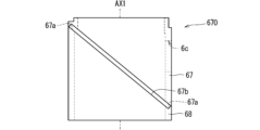
- the third inner housing 68 can function together with the second inner housing 67 as a filter holder 670 for holding the wavelength separation filter 4.
- the third inner housing 68 is located between the wavelength separation filter 4 and the second lens 52.
- the third inner housing 68 has, for example, a cylindrical shape surrounding the optical axis AX1.
- the inner peripheral surface of the third inner housing 68 is located closer to the optical axis AX1 than the peripheral edge of the wavelength separation filter 4.
- the outer peripheral surface of the third inner housing 68 may be in contact with the inner peripheral surface of the side wall 632.
- the peripheral edge of the wavelength separation filter 4 is held between the second inner housing 67 and the third inner housing 68 in the optical axis direction.
- the edge of the second inner housing 67 on the wavelength separation filter 4 side is in contact with the peripheral edge of the first surface 4a of the wavelength separation filter 4, and the edge of the wavelength separation filter 4 of the third inner housing 68 is in contact with the peripheral edge of the first surface 4a of the wavelength separation filter 4.
- the edge on the 4 side is in contact with the peripheral edge of the second surface 4b of the wavelength separation filter 4 on the opposite side to the first surface 4a.
- the end face of the third inner housing 68 facing the wavelength separation filter 4 has a shape along the peripheral edge of the second surface 4b of the wavelength separation filter 4, and the wavelength separation filter It may be inclined to the same extent as the second surface 4b of No. 4.
- An adhesive may be placed between the wavelength separation filter 4 and the second inner housing 67, and an adhesive may be placed between the wavelength separation filter 4 and the third inner housing 68. Often, an adhesive may be located between the wavelength separation filter 4 and the side wall 632.
- the edge of the third inner housing 68 on the second lens 52 side is in contact with the peripheral edge of the second lens 52. According to this, the third inner housing 68 can also function as a spacer that determines the distance between the wavelength separation filter 4 and the second lens 52.
- the fourth inner housing 69 can function as a lens holder that holds the second lens 52 together with the third inner housing 68.
- the fourth inner housing 69 is located between the second lens 52 and the decorative frame portion 65.
- the fourth inner housing 69 has, for example, a cylindrical shape surrounding the optical axis AX1.
- the inner peripheral surface of the fourth inner housing 69 is located closer to the optical axis AX1 than the side surface of the second lens 52.
- the side surface of the second lens 52 is a surface that connects the peripheral edge of the first surface 52a and the peripheral edge of the second surface 52b.
- the outer peripheral surface of the fourth inner housing 69 and the side surface of the second lens 52 may be in contact with the inner peripheral surface of the side wall 632.
- the second lens 52 may fit into the inner peripheral surface of the side wall 632.
- the peripheral edge of the second lens 52 is held between the third inner housing 68 and the fourth inner housing 69 in the optical axis direction. That is, the edge of the third inner housing 68 on the second lens 52 side is in contact with the peripheral edge of the first surface 52a of the second lens 52, and the second lens of the fourth inner housing 69 is in contact with the peripheral edge of the first surface 52a of the second lens 52.
- the edge on the 52 side is in contact with the peripheral edge of the second surface 52b of the second lens 52.
- the fourth inner housing 69 may be attached to the side wall 632, for example.
- the decorative frame portion 65 is attached to the end of the side wall 632 on the opposite side from the opening member 631.
- the decorative frame portion 65 may include a plate-like portion 651 and a cylindrical portion 652.
- the plate-like portion 651 has a plate-like shape, and is positioned with its thickness direction along the optical axis direction.
- the cylindrical portion 652 has a cylindrical shape extending from the periphery of the plate portion 651 toward the wavelength conversion member 3 along the optical axis direction, and is connected to, for example, an end portion of the side wall 632.
- An irradiation aperture 6a is formed in the center of the plate-like portion 651, passing through the plate-like portion 651 in the optical axis direction.
- the diameter of the irradiation opening 6a is smaller than the inner diameter of the fourth inner housing 69, for example.
- the structure consisting of the main body part 63 and the decorative frame part 65 may be constituted by a plurality of structural members as appropriate.
- the structure may be divided into a plurality of constituent members in the optical axis direction. The structure may be assembled by attaching these plurality of components to each other.
- the inner circumferential surface 651a forming the illumination opening 6a of the decorative frame portion 65 may be inclined such that the opening area increases as it approaches the illumination space S1 in the optical axis direction. .
- the inner circumferential surface 651a may be inclined so as to move away from the central axis of the irradiation aperture 6a as it approaches the illumination space S1.
- the second housing section 62 is a member that houses the light source 2.
- the second housing section 62 is attached to the side of the first housing section 61.
- the second housing portion 62 may include a bottom member 621 and a side wall 622.
- a light source 2 is attached to the bottom member 621.
- the side wall 622 has a cylindrical shape extending from the periphery of the bottom member 621 along the optical axis AX2. The edge of the side wall 622 on the opposite side from the light source 2 is connected to the side wall 632 of the first housing section 61 in a state surrounding the introduction opening 6c.
- first housing part 61 and the second housing part 62 there may be a gap between the first housing part 61 and the second housing part 62. Thereby, heat transfer between the first housing part 61 and the second housing part 62 can be inhibited. Therefore, heat can easily escape from the first housing section 61 and the second housing section 62 to the outside. As a result, heat dissipation from the lighting device 1 can be improved.
- the thermal conductivity of the attachment member 64 may be higher than that of the wavelength conversion member 3.
- the material of the mounting member 64 may be a metal material with high thermal conductivity.
- This metal material includes, for example, copper (Cu), aluminum (Al), magnesium (Mg), gold (Au), silver (Ag), iron (Fe), chromium (Cr), cobalt (Co), beryllium ( Applicable materials include Be), molybdenum (Mo), tungsten (W), and alloys.
- the wavelength conversion member 3 can be cooled from the surface 3a side by the mounting member 64.
- the surface 3a of the wavelength conversion member 3 is directly bonded to the surface 64b of the mounting member 64.
- the surface 3a of the wavelength conversion member 3 and the surface 64b of the mounting member 64 can be directly joined. If the attachment member 64 is directly joined to the wavelength conversion member 3, the heat of the wavelength conversion member 3 can be transferred to the attachment member 64 more quickly.
- Such a mounting member 64 can function as a so-called heat sink. Thereby, the extent to which the wavelength conversion member 3 deteriorates due to heat can be reduced.
- the side surface 3c of the wavelength conversion member 3 may also be joined to the attachment member 64. According to this, the heat of the wavelength conversion member 3 can also be transmitted to the attachment member 64 from the side surface 3c. Therefore, the cooling efficiency of the mounting member 64 can be improved.
- the surface 64b of the mounting member 64 may have reflectivity for the fluorescence L1. Reflectivity here means, for example, that the reflectance is high in at least a part of the wavelength range of the fluorescence L1.
- the reflectance may be, for example, 60% or more, 80% or more, or 90% or more. According to this, the fluorescence L1 generated in the wavelength conversion member 3 and directed toward the attachment member 64 is reflected by the surface 64b of the attachment member 64, and proceeds to the first A lens 51A. Therefore, the lighting device 1 can emit the fluorescent light L1 from the irradiation aperture 6a with a larger amount of light.
- the surface 64b of the mounting member 64 may have reflectivity for the excitation light L0.
- the reflectance of the excitation light L0 on the surface 64b of the mounting member 64 may be 60% or more, 80% or more, or 90% or more. According to this, the excitation light L0 that has passed through the wavelength conversion member 3 is reflected by the surface 64b of the attachment member 64 and enters the wavelength conversion member 3 again. Therefore, the amount of fluorescence L1 emitted by the wavelength conversion member 3 can be improved. Therefore, the illumination device 1 can emit the fluorescent light L1 from the irradiation aperture 6a with a higher light intensity.
- the reflectance of visible light on the surface 64b of the mounting member 64 increases, and the excitation light L0 increases. Accordingly, the amount of emitted fluorescent light L1 may increase.
- the housing 6 may be made of the same material. Alternatively, at least two of each part of the housing 6 may be made of a plurality of different materials.
- a material having a higher thermal conductivity than that of other parts of the housing 6 for example, the opening member 631
- a metal material may be used as the material for the mounting member 64
- various synthetic resins may be used as the material for other parts of the housing 6 (for example, the opening member 631).
- the angle ⁇ 1 that defines the numerical aperture of the lens optical system 5 may be equal to or larger than the spread angle ⁇ 1 of the fluorescence L1 passing through the diaphragm aperture 6ba.
- the numerical aperture is the product of the sine of the half value of the angle ⁇ 1 and the refractive index.
- the angle ⁇ 1 is, for example, an angle formed by both outer rays of virtual light that can pass through the effective area of the lens optical system 5.
- the effective area here corresponds to a light passage area where the optical performance of the lens optical system 5 can be exhibited.
- the effective area of the first lens 51 is the area of the first lens 51 excluding a predetermined peripheral width.
- the effective area of the first lens 51 is surrounded by the inner peripheral edge of the part of the housing 6 (here, the opening member 631 and the first inner housing 66) that holds the peripheral edge of the first lens 51. It may be a region.
- the spread angle ⁇ 1 and the angle ⁇ 1 are equal to each other.
- the fluorescence L1 transmitted through the aperture 6ba can pass within the effective area of the lens optical system 5. Therefore, the fluorescence L1 hardly enters the edges of the first lens 51 and the second lens 52 of the lens optical system 5, and unnecessary reflection and scattering of the fluorescence L1 occurring at the edges can be suppressed or avoided.
- the wavelength separation filter 4 is held between the second inner housing 67 and the third inner housing 68, which are separate from each other.
- the filter holder 670 includes a second inner housing 67 and a third inner housing 68 that are separated in the optical axis direction.
- FIG. 5 is a diagram schematically showing a first example of the configuration of the filter holder 670. As shown in FIG. 5, the second inner housing 67 and the third inner housing 68 may be integrally connected in the optical axis direction.
- a concave groove 67a for sandwiching the wavelength separation filter 4 in the optical axis direction is formed on the inner peripheral surface of the cylindrical filter holder 670 consisting of the second inner housing 67 and the third inner housing 68. .
- the concave groove 67a is inclined similarly to the wavelength separation filter 4.
- a peripheral portion of the wavelength separation filter 4 is inserted into the concave groove 67a.
- a slit 67b connected to the concave groove 67a is formed in the side wall of the filter holder 670.
- the slit 67b has an elongated shape and is inclined like the wavelength separation filter 4.
- the wavelength separation filter 4 is inserted into the filter holder 670 through the slit 67b. Thereby, the peripheral portion of the wavelength separation filter 4 is sandwiched between the filter holders 670 in the optical axis direction.
- FIG. 6 is a diagram schematically showing a second example of the configuration of the filter holder 670.
- the cylindrical filter holder 670 may be divided into two separation bodies 671 and 672 in the circumferential direction around the optical axis AX1. In this case, the slit 67b described above is unnecessary.
- the filter holder 670 has a cylindrical shape in the example of FIG. 6, it may have a rectangular tube shape.
- FIG. 7 is a cross-sectional view schematically showing an example of the configuration of the lighting device 1 according to the second embodiment.
- the lighting device 1 according to the second embodiment is different from the lighting device 1 according to the first embodiment in the arrangement of optical elements.
- the wavelength separation filter 4, the second lens 52, and the irradiation aperture 6a are arranged in this order in the linear first direction, and the wavelength conversion member 3, the first lens 51, the wavelength separation filter 4 and The light sources 2 are lined up in this order in a linear second direction intersecting the first direction.
- the first direction and the second direction may be orthogonal.
- the wavelength separation filter 4 transmits the excitation light L0 from the light source 2 toward the wavelength conversion member 3.
- the excitation light L0 that has passed through the wavelength separation filter 4 enters the wavelength conversion member 3 through the first lens 51.
- the wavelength conversion member 3 emits fluorescence L1 based on the excitation light L0. Fluorescence L1 emitted by the wavelength conversion member 3 enters the wavelength separation filter 4 through the first lens 51.
- the wavelength separation filter 4 reflects the fluorescence L1 toward the irradiation aperture 6a.
- the fluorescence L1 reflected by the wavelength separation filter 4 passes through the second lens 52 and exits into the illumination space S1 through the irradiation aperture 6a.
- the first lens 51 is located between the wavelength separation filter 4 and the wavelength conversion member 3. Therefore, in the second embodiment as well, the lighting device 1 can emit the fluorescent light L1 with high efficiency. Moreover, in the second embodiment, no optical element is located on the opposite side of the wavelength separation filter 4 from the irradiation aperture 6a. Therefore, the size of the lighting device 1 in the first direction can be reduced. Therefore, the lighting device 1 according to the second embodiment can be more easily installed in a low-height space under the ceiling.
- FIG. 8 is a diagram schematically showing an example of the configuration of the optical system of the illumination device 1 according to the third embodiment.
- the lighting device 1 according to the third embodiment is different from the lighting device 1 according to the first embodiment in the arrangement of optical elements.
- FIG. 8 only the vicinity of the irradiation opening 6a of the housing 6 is shown, and illustration of other parts is omitted.
- FIG. 9, which will be referred to later only the vicinity of the irradiation opening 6a of the housing 6 is shown, and illustration of other parts is omitted.
- two second A lenses 52A and a second B lens 52B are shown as the second lenses 52.
- the second A lens 52A and the second B lens 52B are arranged in the optical axis direction between the wavelength separation filter 4 and the irradiation aperture 6a.
- the second A lens 52A and the second B lens 52B may be, for example, convex lenses.
- the second A lens 52A and the second B lens 52B condense the fluorescence L1 on the irradiation aperture 6a side.
- a plurality of second lenses 52 are located between the wavelength separation filter 4 and the irradiation aperture 6a. Therefore, it is possible to easily obtain a lens optical system 5 with a high imaging magnification while allowing the fluorescence L1 to pass through the wavelength separation filter 4 in a state closer to parallel light. In other words, the lighting device 1 can emit the fluorescence L1 with a wider spread angle ⁇ 2.
- first lens 51 is shown as the first lens 51 in the example of FIG. 8, two or more first lenses 51 may be located. Further, the number of second lenses 52 is not limited to two, and three or more second lenses 52 may be located. According to this, the optical characteristics necessary for the lens optical system 5 can be obtained more easily.
- FIG. 9 is a diagram schematically showing an example of the configuration of the optical system of the illumination device 1 according to the fourth embodiment.
- the lighting device 1 according to the fourth embodiment is different from the lighting device 1 according to the third embodiment in that a wavelength separation filter 4 is provided.
- the wavelength separation filter 4 includes a dielectric multilayer film 42, a first prism 43, and a second prism 44.
- This wavelength separation filter 4 is also called a dichroic prism.
- the first prism 43 and the second prism 44 are transparent members containing at least one of glass such as optical glass and resin such as acrylic resin, and have, for example, an isosceles right triangular prism shape. .
- the first prism 43 has a slope 43a, a first surface 43b, a second surface 43c, and a pair of first end surfaces (not shown).
- the slope 43a corresponds to the hypotenuse of a right isosceles triangle
- the first surface 43b corresponds to the first equilateral side of the right isosceles triangle
- the second surface 43c corresponds to the second equilateral side of the right isosceles triangle.
- the first surface 43b faces the first lens 51 in the optical axis direction
- the second surface 43c faces the light source 2 in the direction along the optical axis AX2.
- the pair of first end surfaces are surfaces located at both ends in a direction perpendicular to both the optical axis AX1 and the optical axis AX2, respectively.
- the second prism 44 has a slope 44a, a first surface 44b, a second surface 44c, and a pair of second end surfaces (not shown).
- the slope 44a corresponds to the hypotenuse of a right isosceles triangle
- the first surface 44b corresponds to the first equilateral side of the right isosceles triangle
- the second surface 44c corresponds to the second equilateral side of the right isosceles triangle.
- the first surface 44b faces the second lens 52 in the optical axis direction.
- the pair of second end surfaces are surfaces located at both ends in a direction perpendicular to both the optical axis AX1 and the optical axis AX2, respectively.
- the first prism 43 and the second prism 44 are positioned such that the slope 43a and the slope 44a face each other.
- the dielectric multilayer film 42 is located between the slope 43a of the first prism 43 and the slope 44a of the second prism 44.
- Such a wavelength separation filter 4 has a cubic shape as a whole.
- the excitation light L0 from the light source 2 enters the second surface 43c of the first prism 43.
- the second surface 43c of the first prism 43 is perpendicular to the optical axis AX2 of the light source 2, for example.
- the excitation light L0 travels inside the first prism 43 from the second surface 43c toward the dielectric multilayer film 42, and is reflected by the dielectric multilayer film 42.
- the excitation light L0 reflected by the dielectric multilayer film 42 travels inside the first prism 43 toward the first surface 43b, and passes through the first surface 43b.
- the first surface 43b of the first prism 43 is, for example, orthogonal to the optical axis AX1.
- the excitation light L0 enters the wavelength conversion member 3 from the first surface 43b through the first lens 51.
- the wavelength conversion member 3 emits fluorescence L1 based on the excitation light L0.
- the fluorescence L1 emitted by the wavelength conversion member 3 enters the first surface 43b of the first prism 43 through the first lens 51.
- the fluorescence L1 travels from the first surface 43b inside the first prism 43 toward the dielectric multilayer film 42, and is transmitted through the dielectric multilayer film 42.
- the fluorescence L1 that has passed through the dielectric multilayer film 42 travels inside the second prism 44 toward the first surface 44b, and passes through the first surface 44b.
- the first surface 44b of the second prism 44 is, for example, substantially parallel to the first surface 43b of the first prism 43 and perpendicular to the optical axis AX1.
- the fluorescence L1 travels from the first surface 44b of the second prism 44 to the second lens 52, and is emitted through the second lens 52 from the irradiation aperture 6a into the illumination space S1.
- the fluorescence L1 enters the wavelength separation filter 4 at the first surface 43b of the first prism 43 perpendicular to the optical axis direction, and enters the wavelength separation filter 4 at the second prism parallel to the first surface 43b.
- the light is emitted from the first surface 44b of 44. Therefore, it is possible to reduce the deviation of the optical path of the fluorescence L1 in the width direction perpendicular to the optical axis direction, which occurs when the fluorescence L1 passes through the wavelength separation filter 4. That is, the optical axis AX1 of the first lens 51 located between the wavelength separation filter 4 and the wavelength conversion member 3 and the optical axis of the second lens 52 located between the wavelength separation filter 4 and the irradiation aperture 6a. It is possible to reduce the amount of positional deviation between the two. According to this, it is sufficient to hold the first lens 51 and the second lens 52 substantially coaxially, and the design of the housing 6 is easy.
- the wavelength separation filter 4 has a cubic shape in the above example, it may have a cylindrical shape with the optical axis direction as the height direction, for example.
- the lighting device 1 has been described in detail as described above, the above description is an example in all aspects, and the lighting device 1 is not limited thereto. It is understood that countless variations not illustrated can be envisioned without departing from the scope of this disclosure. The configurations described in each of the above embodiments and modifications can be appropriately combined or omitted as long as they do not contradict each other.
- the first lens 51 and the second lens 52 are not necessarily limited to convex lenses. Concave lenses, meniscus lenses and convex lenses may be employed as appropriate. Further, the first lens 51 may be a spherical lens or an aspherical lens. The second lens 52 may also be a spherical lens or an aspherical lens.
- This disclosure includes the following content.
- the illumination device includes a housing having a first opening, a light source that emits excitation light, and is located inside the housing, and the excitation light from the light source is incident. , a wavelength conversion member that emits fluorescence having a different spectrum from the excitation light based on the excitation light; and a wavelength conversion member located inside the casing, guiding the excitation light from the light source to the wavelength conversion member, a wavelength separation filter that guides the fluorescence from the wavelength conversion member to the first opening; and a wavelength separation filter that is located between the wavelength separation filter and the wavelength conversion member inside the housing, and that converts the excitation light into the wavelength conversion. and a lens optical system including one or more first lenses that condense light onto a member and transmit the fluorescence from the wavelength conversion member toward the effective surface of the wavelength separation filter.
- the lens optical system may form an image of the fluorescence from the wavelength conversion member on the first aperture side and emit the fluorescence from the first aperture.
- the imaging magnification of the lens optical system may be less than or equal to the ratio of the size of the first aperture to the size of the fluorescence in the wavelength conversion member.
- the first lens includes a first A lens located between the wavelength conversion member and the wavelength separation filter, and a first A lens located between the wavelength conversion member and the wavelength separation filter.
- a first B lens located closer to the wavelength separation filter than the first A lens is between the first A lens and the filter.
- the refractive power of the first A lens may be greater than the refractive power of the first B lens.
- the size of the first B lens may be larger than the size of the first A lens.
- the first lens has a first surface on the wavelength conversion member side and a second surface on the wavelength separation filter side.
- the curvature of the first surface may be smaller than the curvature of the second surface.
- the lens optical system may further include a second lens located between the wavelength separation filter and the first aperture.
- the spread angle of the fluorescence emitted from the first aperture is smaller than the spread angle of the fluorescence incident on the lens optical system. You can.
- the wavelength conversion member, the wavelength separation filter, and the first opening may be arranged in a predetermined first direction, and the light source and The wavelength separation filters may be arranged in a second direction intersecting the first direction, and the wavelength separation filters may reflect the excitation light from the light source toward the wavelength conversion member; The fluorescence from the wavelength conversion member can be transmitted toward the first opening.
- the first lens and the second lens can be arranged in the first direction.
- the wavelength separation filter and the first aperture may be arranged in a predetermined first direction, and the light source, the wavelength separation filter and The wavelength conversion members can be arranged in a second direction intersecting the first direction, and the wavelength separation filter can transmit the excitation light from the light source to the wavelength conversion member side, and the wavelength separation filter can transmit the excitation light from the light source to the wavelength conversion member side.
- the fluorescence from the conversion member can be reflected toward the first opening.
- the angle between the dielectric multilayer film of the wavelength separation filter and the first direction may be 45 degrees or more.
- the casing includes a filter holder that sandwiches a peripheral portion of the wavelength separation filter in a direction along the optical axis of the first lens. can be included.
- the illumination device allows the fluorescence of a predetermined spread angle or less to pass to the lens optical system side, out of the fluorescence from the wavelength conversion member, and
- the apparatus may further include an aperture member having a second aperture that blocks the fluorescence larger than a predetermined spread angle.
- the angle that defines the numerical aperture of the lens optical system may be equal to or greater than the predetermined spread angle.
- the inner circumferential surface of the aperture member forming the second aperture has a sloped portion such that the aperture area increases as it approaches the wavelength conversion member.
- the first lens may be located in the second aperture.
- the housing may further include an inner housing that sandwiches the peripheral edge of the first lens together with the opening member, and the first lens may include the wavelength conversion member. and a second surface on the side of the wavelength separation filter, the aperture member can be in contact with a peripheral edge of the first surface of the first lens, and the inner housing may include a pressing member, and the pressing member is located closer to the wavelength separation filter than the first sloped surface that is in contact with the peripheral edge of the second surface of the first lens.
- the second inclined surface may be inclined away from the optical axis of the first lens as it approaches the wavelength separation filter.
- the housing closes the second opening with respect to the surface of the opening member on the opposite side from the wavelength separation filter.
- the wavelength converting member may be located in a region of the mounting member facing the second opening.
- the thermal conductivity of the mounting member may be higher than the thermal conductivity of the wavelength conversion member.
- the casing includes a first casing part that houses the wavelength separation filter and the lens optical system, and a first casing part that houses the light source. 2 housing parts, and the first housing part can have a third opening that allows the excitation light from the light source to pass toward the wavelength separation filter.
- first lens 51A first lens (first A lens) 51Aa 1st surface 51Ab 2nd surface 51B 1st lens (1st B lens) 52 Second lens 52A Second lens (second A lens) 52B 2nd lens (2nd B lens) 6 Housing 61 First housing part 62 Second housing part 631 Opening member 66 Inner housing (first inner housing) 661 Holding member 670 Filter holder 6a First opening (irradiation opening) 6b Second opening (opening) 6c Third opening (introduction opening) L0 Excitation light L1 Fluorescence
Landscapes
- Engineering & Computer Science (AREA)
- General Engineering & Computer Science (AREA)
- Physics & Mathematics (AREA)
- Spectroscopy & Molecular Physics (AREA)
- Non-Portable Lighting Devices Or Systems Thereof (AREA)
Abstract
照明装置は、筐体と、光源と、波長変換部材と、波長分離フィルタと、レンズ光学系とを備える。筐体は第1開口を有する。光源は励起光を出射する。波長変換部材は筐体の内部に位置している。波長変換部材には、光源からの励起光が入射する。波長変換部材は、励起光と異なるスペクトルを有する蛍光を、励起光に基づいて発する。波長分離フィルタは筐体の内部に位置しており、光源からの励起光を波長変換部材に導き、波長変換部材からの蛍光を第1開口に導く。レンズ光学系は1以上の第1レンズを含む。第1レンズは、筐体の内部において波長分離フィルタと波長変換部材との間に位置しており、励起光を波長変換部材に集光させ、かつ、波長変換部材からの蛍光を波長分離フィルタの有効面に向かって前記蛍光を透過させる。
Description
本出願は、日本国出願2022-108911号(2022年7月6日出願)の優先権を主張するものであり、当該出願の開示全体を、ここに参照のために取り込む。
本開示は、照明装置に関する。
従来から、光源、ビームスプリッタおよび波長変換部材を含む発光デバイスが提案されている(例えば特許文献1)。
照明装置が開示される。
一実施形態において、照明装置は、筐体と、光源と、波長変換部材と、波長分離フィルタと、レンズ光学系とを備える。筐体は第1開口を有する。光源は励起光を出射する。波長変換部材は筐体の内部に位置している。波長変換部材には、光源からの励起光が入射する。波長変換部材は、励起光と異なるスペクトルを有する蛍光を、励起光に基づいて発する。波長分離フィルタは筐体の内部に位置しており、光源からの励起光を波長変換部材に導き、波長変換部材からの蛍光を第1開口に導く。レンズ光学系は1以上の第1レンズを含む。第1レンズは、筐体の内部において波長分離フィルタと波長変換部材との間に位置しており、励起光を波長変換部材に集光させ、かつ、波長変換部材からの蛍光を波長分離フィルタの有効面に向かって前記蛍光を透過させる。
発明者は、照明装置において、より高い効率で照明光を出射することができる技術を創出した。以下、第1の実施形態から第4の実施形態にかかる照明装置1を図面に基づいて説明する。
<1.第1の実施形態>
<1-1.照明装置1の概略構成>
図1は、第1の実施形態にかかる照明装置1の構成の一例を概略的に示す断面図である。図2は、第1の実施形態にかかる照明装置1における光の経路の一例を概略的に示す断面図である。図3は、図1の照明装置1の一部の構成を拡大して示す拡大断面図である。図1から図3では、後述の光軸AX1を含む断面における照明装置1の構成の一例が示されている。
<1-1.照明装置1の概略構成>
図1は、第1の実施形態にかかる照明装置1の構成の一例を概略的に示す断面図である。図2は、第1の実施形態にかかる照明装置1における光の経路の一例を概略的に示す断面図である。図3は、図1の照明装置1の一部の構成を拡大して示す拡大断面図である。図1から図3では、後述の光軸AX1を含む断面における照明装置1の構成の一例が示されている。
図2で示されるように、照明装置1は、照明光としての蛍光L1を照明空間S1に出射する装置である。照明空間S1は例えば建築物の室内空間である。照明装置1は例えば照明空間S1の天井部に配置される。
照明装置1は、光源2と、波長変換部材3と、波長分離フィルタ4と、レンズ光学系5と、筐体6とを含んでいる。以下では、まず、各構成の一例について概説し、その後、詳述する。
筐体6は、光源2、波長変換部材3、波長分離フィルタ4およびレンズ光学系5を収納している。筐体6は第1開口(以下、照射開口とも呼ぶ)6aを有している。照明光としての蛍光L1が照射開口6aから照明空間S1に出射される。
光源2は、励起光L0を出射する出射部(例えば出射面)21を有している。励起光L0は、例えば、380nmから415nmまでの波長範囲内にピークを持つ光であってもよい。具体的な一例として、励起光L0は、405nm近傍にピークを有する紫色の光であってもよい。なお、励起光L0は必ずしも紫色の光に限らず、例えば、450nm近傍にピークを有する青色の光であってもよい。
光源2からの励起光L0は波長分離フィルタ4に入射する。図2の例では、励起光L0の外側の輪郭の一例が破線で模式的に示されている。波長分離フィルタ4は筐体6の内部に位置しており、励起光L0を波長変換部材3に導く。図1および図2の例では、波長変換部材3および波長分離フィルタ4は、後述の光軸AX1に沿う方向(第1方向に相当)に沿って並んでおり、光源2および波長分離フィルタ4は、第1方向に交差する第2方向に沿って並んでいる。この場合、波長分離フィルタ4は光源2からの励起光L0を波長変換部材3に向けて反射させる。
レンズ光学系5は、筐体6の内部において波長分離フィルタ4と波長変換部材3との間に位置する1以上の第1レンズ51を含んでいる。図1および図2の例では、第1レンズ51として、第1Aレンズ51Aおよび第1Bレンズ51Bが示されている。第1Aレンズ51Aは第1Bレンズ51Bに対して波長変換部材3側に位置している。波長分離フィルタ4で反射した励起光L0は、第1Bレンズ51Bおよび第1Aレンズ51Aをこの順で透過し、波長変換部材3に入射する。第1Aレンズ51Aおよび第1Bレンズ51Bは、波長分離フィルタ4からの励起光L0を波長変換部材3に集光させる。なお、波長分離フィルタ4と波長変換部材3との間の第1レンズ51の個数は2つに限らず、1つであってもよく、あるいは、3つ以上であってもよい。また、以下では、第1Aレンズ51Aの光軸を光軸AX1とも呼び、光軸AX1に沿う方向を光軸方向とも呼ぶ。
波長変換部材3は、例えば、表面3a、表面3bおよび側面3cを有している。表面3bは、波長変換部材3のうちの第1レンズ51側の表面である。表面3aは、波長変換部材3のうちの表面3bとは逆側の表面である。側面3cは、波長変換部材3のうちの表面3aの周縁および表面3bの周縁を連結する側面である。波長変換部材3は板状の形状を有していてもよい。つまり、波長変換部材3の表面3aおよび表面3bは略平坦面であり、互いに略平行であってもよい。波長変換部材3は、その厚み方向が光軸方向に沿う姿勢で位置している。図1および図2の例では、波長変換部材3の表面3aは筐体6の取付部材64によって覆われている。取付部材64については後に詳述する。
第1レンズ51を透過した励起光L0は波長変換部材3の表面3bに入射する。波長変換部材3は蛍光体を含んでおり、入射した励起光L0に基づいて、励起光L0とは異なるスペクトルを有する蛍光L1を発する。例えば、蛍光L1のピーク波長は励起光L0のピーク波長よりも長く、蛍光L1は可視光である。波長変換部材3から出射された蛍光L1の広がり角は大きく、例えば、180度程度である。
波長変換部材3からの蛍光L1の少なくとも一部は第1レンズ51(ここでは、第1Aレンズ51Aおよび第1Bレンズ51B)を透過して波長分離フィルタ4に入射する。図2では、第1Aレンズ51Aに入射する蛍光L1の外側の輪郭の一例が模式的に二点鎖線で示されている。第1Aレンズ51Aおよび第1Bレンズ51Bは蛍光L1を波長分離フィルタ4の有効面に向かって透過させる。ここでいう有効面とは、波長分離フィルタ4のフィルタ機能を実現できる範囲をいう。波長分離フィルタ4は蛍光L1を照射開口6aに導く。図1および図2の例では、波長変換部材3、波長分離フィルタ4および照射開口6aは光軸方向において並んでいる。この場合には、波長分離フィルタ4は蛍光L1を照射開口6aに向けて透過させる。
図2で示されるように、レンズ光学系5は、筐体6の内部において波長分離フィルタ4と照射開口6aとの間に位置する第2レンズ52をさらに含んでいてもよい。第1レンズ51および第2レンズ52は光軸上に並んでいる。この場合、波長分離フィルタ4からの蛍光L1は第2レンズ52を透過し、照射開口6aを通じて照明空間S1に出射される。
以上のように、照明装置1においては、波長分離フィルタ4と波長変換部材3との間に1以上の第1レンズ51が位置している。この第1レンズ51によって、波長変換部材3から大きな広がり角で進む蛍光L1を絞ることができる。つまり、第1レンズ51が蛍光L1の広がり角を低減させることができる。これにより、波長分離フィルタ4の大型化を招くことなく、より多くの蛍光L1を波長分離フィルタ4へと導くことができる。つまり、波長変換部材3が発する蛍光L1の全体のうち、より多くの蛍光L1を波長分離フィルタ4を通じて照射開口6aへ導くことができる。逆に言えば、波長変換部材3が発する蛍光L1の全体のうち、照射開口6aに向かわない蛍光L1の割合を低減させることができる。これによれば、照明装置1は、より高い効率で蛍光L1を照明空間S1に出射することができる。
また、第1Aレンズ51Aを波長変換部材3の近くに配置することにより、波長変換部材3からの蛍光L1のさらに多くを第1Aレンズ51Aに入射させることができる。このため、照明装置1は、さらに高い効率で蛍光L1を照明空間S1に出射することができる。
しかも、照明装置1によれば、波長分離フィルタ4からの励起光L0は1以上の第1レンズ51を透過して波長変換部材3に入射する。このため、たとえ波長変換部材3と第1Aレンズ51Aとの間隔が狭くても、励起光L0は波長変換部材3の比較的に広い表面3bに適切に入射することができる。波長変換部材3はより広い範囲で蛍光L1を生じさせることができるので、より大きな光量で蛍光L1を生じさせることができる。ひいては、照明装置1は、より大きな光量で蛍光L1を照明空間S1に出射することができる。
以下、照明装置1の各構成のより具体的な一例について、光学系および筐体6に大別して説明する。まず、光学系について説明し、その後、筐体6について説明する。
<1-2.光学系>
<1-2-1.光源2>
光源2は、例えば、レーザーダイオード(laser diode:LD)などの半導体レーザ素子、VCSEL(Vertical Cavity Surface Emitting LASER)、発光ダイオード(light Emitting diode:LED)およびSLD(super luminescent diode)などの発光素子を含んでもよい。光源2の出射部21は、該発光素子の出射端であってもよい。該発光素子には、例えば、405nmの紫色のレーザ光を励起光L0として放出する窒化ガリウム(GaN)系の半導体レーザが適用されてもよい。
<1-2-1.光源2>
光源2は、例えば、レーザーダイオード(laser diode:LD)などの半導体レーザ素子、VCSEL(Vertical Cavity Surface Emitting LASER)、発光ダイオード(light Emitting diode:LED)およびSLD(super luminescent diode)などの発光素子を含んでもよい。光源2の出射部21は、該発光素子の出射端であってもよい。該発光素子には、例えば、405nmの紫色のレーザ光を励起光L0として放出する窒化ガリウム(GaN)系の半導体レーザが適用されてもよい。
あるいは、光源2は発光素子に加えて、ファイバおよびロッドレンズ等の導光部材をさらに含んでもよい。ファイバは線状のコアとクラッドを含む。クラッドはコアよりも低い屈折率を有し、コアを被覆する。励起光L0はコアとクラッドとの間の境界面で全反射しながらコア内を透過することができる。ロッドレンズは例えば柱状の形状を有している。励起光L0はロッドレンズの側面で全反射しながらロッドレンズの内部を透過することができる。このような導光部材の入射端は、ファイバの長手方向の端に位置する第1端面またはロッドレンズの端に位置する第1端面に相当し、導光部材の出射端は、ファイバの第1端面とは逆側の第2端面またはロッドレンズの第1端面とは逆側の第2端面に相当する。発光素子からの励起光L0は導光部材の入射端に入射し、導光部材内を進んで導光部材の出射端から出射する。この場合、光源2の出射部21は導光部材の出射端に相当する。
光源2は、直線偏光を有する励起光L0を出射してもよい。励起光L0の偏光は、例えば、波長分離フィルタ4の入射面についてのs偏光であってもよい。また、光源2と波長分離フィルタ4との間に種々のレンズが位置していてもよい。
<1-2-2.波長分離フィルタ4>
波長分離フィルタ4は、上記のように、光源2からの励起光L0を波長変換部材3に導き、波長変換部材3からの蛍光L1を照射開口6aに導く。図2の例では、波長分離フィルタ4は励起光L0を波長変換部材3に向けて反射させ、蛍光L1を照射開口6aに向けて透過させる。波長分離フィルタ4は、例えば、ダイクロイックミラーあるいはダイクロイックフィルムとも呼ばれる。
波長分離フィルタ4は、上記のように、光源2からの励起光L0を波長変換部材3に導き、波長変換部材3からの蛍光L1を照射開口6aに導く。図2の例では、波長分離フィルタ4は励起光L0を波長変換部材3に向けて反射させ、蛍光L1を照射開口6aに向けて透過させる。波長分離フィルタ4は、例えば、ダイクロイックミラーあるいはダイクロイックフィルムとも呼ばれる。
図1および図2で示されるように、波長分離フィルタ4は、基材41と、誘電体多層膜42とを含んでいてもよい。基材41は、例えば、光学ガラス等のガラスおよびアクリル樹脂等の樹脂の少なくともいずれか一方を含む透明部材であり、平板状の形状を有していてもよい。誘電体多層膜42は例えば基材41の第1面4aまたは第2面4bの上に位置している。誘電体多層膜42は、例えば、誘電体の薄膜が複数回繰り返して積層された構造を有する。誘電体としては、例えば、酸化ケイ素(SiO2)、酸化チタン(TiO2)、酸化アルミニウム(Al2O3)、酸化ジルコニウム(ZrO2)、酸化タンタル(Ta2O5)および酸化ニオブ(Nb2O3)のうちの1つ以上の材料が適用される。例えば、誘電体多層膜42を構成する複数の誘電体の薄膜の膜厚を適宜設定することで、誘電体多層膜42における励起光L0を反射し且つ蛍光L1を透過させる分光透過率が実現され得る。波長分離フィルタ4では、第1面4aに波長を分離する誘電体多層膜を有しており、第2面4bに反射防止膜を有していてもよい。これにより、第2面4bに誘電体多層膜が位置するである場合と比較して、波長分離フィルタ4の基材41の吸収によって光量が低下するおそれを低減できる。
図4は、波長分離フィルタ4の分光透過率の一例を示すグラフである。図4には、s偏光に対する波長分離フィルタ4の透過率Ts、および、無偏光に対する波長分離フィルタ4の透過率Tnが示されている。ここでは、励起光L0の偏光状態はs偏光であり、その波長は405nmである。図4の例では、励起光L0についての透過率Tsはほぼゼロであるので、励起光L0は波長分離フィルタ4をほとんど透過しない。簡単のために、波長分離フィルタ4の吸収率をほぼゼロとすると、励起光L0はほぼ100%の反射率で波長分離フィルタ4で反射する。一方、蛍光L1の偏光状態は無偏光である。図4の例では、450nm以上の波長範囲における透過率Tnはほぼ100%であるので、450nm以上の波長を有する蛍光L1は波長分離フィルタ4をほぼ100%で透過する。
励起光L0についての波長分離フィルタ4の反射率(例えば、波長が420nm以下である場合の反射率)は、例えば、80%以上であってもよく、90%以上であってもよく、95%以上であってもよい。蛍光L1についての波長分離フィルタ4の透過率Tn(例えば、波長が450nm以上である場合の透過率Tn)は、例えば、80%以上であってもよく、90%以上であってもよく、95%以上であってもよい。
以上のように、波長分離フィルタ4は励起光L0を反射し、蛍光L1を透過させる。図1の例では、波長分離フィルタ4は、その厚み方向が第1レンズ51の光軸AX1に対して約45度に近い角度で交差する姿勢で位置している。また、図1の例では、光源2からの励起光L0の出射方向は、波長分離フィルタ4の誘電体多層膜42の表面に対して45度に近い角度で交差する。これにより、光源2からの励起光L0を波長変換部材3に向けて反射させることができる。波長分離フィルタ4の姿勢および励起光L0の出射方向の具体的な一例については後に述べる。
<1-2-3.レンズ光学系5(第1レンズ51)>
図1で示されるように、第1レンズ51(ここでは第1Aレンズ51Aおよび第1Bレンズ51B)は例えば両凸レンズであってもよい。第1レンズ51は、光学ガラス等のガラスおよびアクリル樹脂等の樹脂の少なくともいずれか一方を含む材料によって形成される。第1Aレンズ51Aおよび第1Bレンズ51Bは波長分離フィルタ4からの励起光L0を波長変換部材3に集光させる。図2の例では、励起光L0が第1Bレンズ51Bおよび第1Aレンズ51Aを透過するたびに、励起光L0の広がりの程度は小さくなる。図2の例では、第1Bレンズ51Bを透過した励起光L0の、光軸AX1に直交する断面の大きさは、波長変換部材3に向かって進むにつれて小さくなっている。つまり、励起光L0は狭まりながら波長変換部材3に向かって進む。
図1で示されるように、第1レンズ51(ここでは第1Aレンズ51Aおよび第1Bレンズ51B)は例えば両凸レンズであってもよい。第1レンズ51は、光学ガラス等のガラスおよびアクリル樹脂等の樹脂の少なくともいずれか一方を含む材料によって形成される。第1Aレンズ51Aおよび第1Bレンズ51Bは波長分離フィルタ4からの励起光L0を波長変換部材3に集光させる。図2の例では、励起光L0が第1Bレンズ51Bおよび第1Aレンズ51Aを透過するたびに、励起光L0の広がりの程度は小さくなる。図2の例では、第1Bレンズ51Bを透過した励起光L0の、光軸AX1に直交する断面の大きさは、波長変換部材3に向かって進むにつれて小さくなっている。つまり、励起光L0は狭まりながら波長変換部材3に向かって進む。
第1Aレンズ51Aおよび第1Bレンズ51Bは、励起光L0を波長変換部材3の表面3bの一部に入射させてもよく、波長変換部材3の表面3bの全部に入射させてもよい。波長変換部材3は励起光L0に基づいて蛍光L1を発する。
第1Aレンズ51Aおよび第1Bレンズ51Bは、波長変換部材3からの蛍光L1を波長分離フィルタ4の有効面に向かって透過させる。図1の例では、蛍光L1が第1Aレンズ51Aおよび第1Bレンズ51Bを透過するたびに、蛍光L1の広がりの程度は小さくなる。図2の例では、第1Bレンズ51Bを透過した蛍光L1の断面の大きさは、第2レンズ52に向かうにつれて一旦は低減し、ウェスト部BWを経て増加している。ウェスト部BWとは、第1Bレンズ51Bと第2レンズ52との間において蛍光L1の断面が最も小さくなる部分である。図2で示されるように、ウェスト部BWは光軸方向において波長分離フィルタ4の中央部と重なる位置にあってもよい。言い換えれば、ウェスト部BWが光軸方向において波長分離フィルタ4の中央部と重なるように、1以上の第1レンズ51が設計されてもよい。
以上のように、1以上の第1レンズ51は、波長分離フィルタ4からの励起光L0を波長変換部材3に集光させる機能と、波長変換部材3からの蛍光L1を波長分離フィルタ4の有効面に向かって透過させる機能とを有している。
<1-2-4.波長変換部材3>
波長変換部材3は蛍光体を含んでいる。波長変換部材3は、励起光L0を青色の光に変換する波長変換材料(つまり、蛍光材料)として、例えば、BaMgAl10O17:Eu、または、(Sr,Ca,Ba)10(PO4)6Cl2:Eu,(Sr,Ba)10(PO4)6Cl2:Eu等を含んでよい。波長変換部材3は、励起光L0を青緑色の光に変換する波長変換材料として、例えば、(Sr,Ba,Ca)5(PO4)3Cl:Eu,Sr4Al14O25:Eu等を含んでよい。波長変換部材3は、励起光L0を緑色の光に変換する波長変換材料として、例えば、SrSi2(O,Cl)2N2:Eu、(Sr,Ba,Mg)2SiO4:Eu2+、または、ZnS:Cu,Al、Zn2SiO4:Mn等を含んでよい。波長変換部材3は、励起光L0を赤色の光に変換する波長変換材料として、例えば、Y2O2S:Eu、Y2O3:Eu、SrCaClAlSiN3:Eu2+、CaAlSiN3:Eu、または、CaAlSi(ON)3:Eu等を含んでよい。波長変換部材3は、励起光L0を近赤外領域の波長を有する光に変換する波長変換材料として、3Ga5O12:Cr等を含んでよい。波長変換部材3が、複数色の光に対応した複数種類の波長変換材料を含んでいれば、波長変換部材3は、演色性の高い蛍光L1を発することができる。具体的には、励起光L0が380nmから415nmにピークを有する光であって、波長変換部材3が赤緑青の光に対応した蛍光体を有していている場合は、蛍光L1の演色性を高めることができる。
波長変換部材3は蛍光体を含んでいる。波長変換部材3は、励起光L0を青色の光に変換する波長変換材料(つまり、蛍光材料)として、例えば、BaMgAl10O17:Eu、または、(Sr,Ca,Ba)10(PO4)6Cl2:Eu,(Sr,Ba)10(PO4)6Cl2:Eu等を含んでよい。波長変換部材3は、励起光L0を青緑色の光に変換する波長変換材料として、例えば、(Sr,Ba,Ca)5(PO4)3Cl:Eu,Sr4Al14O25:Eu等を含んでよい。波長変換部材3は、励起光L0を緑色の光に変換する波長変換材料として、例えば、SrSi2(O,Cl)2N2:Eu、(Sr,Ba,Mg)2SiO4:Eu2+、または、ZnS:Cu,Al、Zn2SiO4:Mn等を含んでよい。波長変換部材3は、励起光L0を赤色の光に変換する波長変換材料として、例えば、Y2O2S:Eu、Y2O3:Eu、SrCaClAlSiN3:Eu2+、CaAlSiN3:Eu、または、CaAlSi(ON)3:Eu等を含んでよい。波長変換部材3は、励起光L0を近赤外領域の波長を有する光に変換する波長変換材料として、3Ga5O12:Cr等を含んでよい。波長変換部材3が、複数色の光に対応した複数種類の波長変換材料を含んでいれば、波長変換部材3は、演色性の高い蛍光L1を発することができる。具体的には、励起光L0が380nmから415nmにピークを有する光であって、波長変換部材3が赤緑青の光に対応した蛍光体を有していている場合は、蛍光L1の演色性を高めることができる。
また、波長変換部材3は、蛍光体の微粒子どうしを連結するためのバインダなどの樹脂を含んでいてもよい。
波長変換部材3からの蛍光L1は広がりながら第1レンズ51に向かって進む。このため、光軸AX1に沿って見た波長変換部材3のサイズは、第1Aレンズ51Aのサイズよりも小さく設定されてもよい。逆に言えば、第1Aレンズ51Aのサイズは波長変換部材3のサイズよりも大きく設定されてもよい。波長変換部材3が、光軸AX1を中心とした円板状の形状を有している場合には、波長変換部材3の直径は第1Aレンズ51Aの直径よりも短くてもよい。例えば、波長変換部材3の直径は、2mmから4mm程度に設定され得る。波長変換部材3が矩形状の形状を有している場合には、波長変換部材3の対角が2mmから4mm程度に設定され得る。第1Aレンズ51Aの直径または対角は、例えば、4mmから15mm程度に設定され得る。
この構造によれば、波長変換部材3からの蛍光L1をより広い範囲で第1Aレンズ51Aに入射させることができる。図1および図2で示されるように、波長変換部材3と第1Aレンズ51Aとの間隔は、第1Aレンズ51Aと第1Bレンズ51Bとの間隔より狭くてもよい。波長変換部材3と第1Aレンズ51Aとの間隔は例えば1mm程度以下に設定され、第1Aレンズ51Aと第1Bレンズ51Bとの間隔は例えば2mm程度以上に設定される。波長変換部材3と第1Aレンズ51Aとの間隔を狭く設定することにより、波長変換部材3が発した蛍光L1のうちのより多くの部分を第1Aレンズ51Aに入射させることができる。
<1-2-5.レンズ光学系5(第2レンズ52)>
第2レンズ52は例えば凸レンズであってもよい。第2レンズ52は波長分離フィルタ4と照射開口6aとの間に位置している。第2レンズ52は波長分離フィルタ4からの蛍光L1を照射開口6a側において集光させる。なお、波長分離フィルタ4と照射開口6aとの間に位置する第2レンズ52の個数は1つに限らず、2つ以上であってもよい。
第2レンズ52は例えば凸レンズであってもよい。第2レンズ52は波長分離フィルタ4と照射開口6aとの間に位置している。第2レンズ52は波長分離フィルタ4からの蛍光L1を照射開口6a側において集光させる。なお、波長分離フィルタ4と照射開口6aとの間に位置する第2レンズ52の個数は1つに限らず、2つ以上であってもよい。
レンズ光学系5は、波長変換部材3の像を仮想的な像面IS1に形成させる結像光学系であってもよい。つまり、図1および図2の例では、第1Aレンズ51A、第1Bレンズ51Bおよび第2レンズ52が該結像光学系を構成する。波長変換部材3は像面IS1に対して共役関係を有している。なお、ここでいう共役関係とは厳密な意味でなく、波長変換部材3より照射開口6a側において、蛍光L1が最も集光された部位(光軸AX1に垂直な断面における蛍光L1の大きさが最も小さい部位)を像面IS1と見なすことができる。
像面IS1は、例えば、照射開口6aに位置していてもよい。像面IS1は、平面であってもよく、湾曲面であってもよい。蛍光L1は像面IS1で集光しつつ、照射開口6aを通じて、照明空間S1に出射される。なお、像面IS1は必ずしも照射開口6aの内部に位置する必要はない。像面IS1は、図2で示されるように、照射開口6aの内部空間と筐体6の内部空間との境界に位置していてもよい。あるいは、像面IS1は、該境界から筐体6の内部空間側にわずかにずれて位置してもよい。あるいは、像面IS1は、照射開口6aの内部空間と照明空間S1との境界に位置していてもよく、該境界から照明空間S1側にわずかにずれて位置していてもよい。
この照明装置1において、レンズ光学系5の結像倍率は、波長変換部材3における蛍光L1の大きさM1に対する照射開口6aの大きさM3の比(=M3/M1)以下であってもよい。波長変換部材3の表面3bの全体から蛍光L1が発する場合には、波長変換部材3における蛍光L1の大きさM1は、波長変換部材3の表面3b自体の大きさである、ともいえる。照射開口6aの大きさM3は、光軸方向に沿って見た照射開口6aの開口面積の最小値である。軸方向に沿って見て、照射開口6aが円状の形状を有する場合、その直径は例えば5mmから15mm程度に設定され得る。軸方向に沿って見て、照射開口6aが矩形状の形状を有する場合、その対角は例えば5mmから15mm程度に設定され得る。
結像倍率とは、波長変換部材3の表面3bにおける蛍光L1の大きさM1に対する像面IS1における蛍光L1の大きさM2の比である。
なお、蛍光L1の大きさは、光軸AX1に垂直な断面において、蛍光L1の光量分布におけるピーク値のe2分の1の光量を有する等高線によって規定されてもよい。ここで、「e」はネイピア数と呼ばれる。言い換えれば、図2の蛍光L1の両外側の光線は、光軸AX1に垂直な断面における光量分布のピーク値のe2分の1の光量を有する光線であってもよい。上記の等高線(つまり、両外側の光線)で囲まれる領域よりも外側の領域における光はノイズ光としてみなされてもよい。
結像倍率が上記比以下であれば、像面IS1における蛍光L1の大きさM2を照射開口6aの大きさM3以下にすることができる。よって、蛍光L1が、筐体6のうちの照射開口6aの周縁部に入射する可能性を低減させることができる。これにより、照射開口6aから漏れ出る不要な反射散乱光を低減させることができる。
また、レンズ光学系5の結像倍率は、照射開口6a内を通過する蛍光L1の大きさが照射開口6aよりも小さくなるように、設定されてもよい。これによれば、反射散乱光をさらに低減させることができる。
また、図2および図3を参照して、照明空間S1における蛍光L1の広がり角θ2は、レンズ光学系5に入射する蛍光L1の広がり角θ1よりも小さい。言い換えれば、広がり角θ2が広がり角θ1よりも小さくなるように、レンズ光学系5が設計される。広がり角θ1は、レンズ光学系5の直前における蛍光L1の広がり角であるともいえ、広がり角θ2は、像面IS1の直後における蛍光L1の広がり角であるともいえる。広がり角θ2に関する具体的な一例として、照明空間S1における蛍光L1の配向角(例えば半値角)は、60度以下程度である。照明装置1の配向角は、例えば45度未満、30度未満または15度未満であってもよい。これにより、例えば一定間隔で複数の照明装置1が設置された照明空間S1において、視界に入る照明装置1のグレアを低減できる。その結果、照明空間S1の快適性を高めることができる。
<1-2-6.レンズ光学系5の各種レンズの更なる詳細>
次に、第1Aレンズ51Aおよび第1Bレンズ51Bの例について、さらに詳述する。図1および図2で示されるように、波長変換部材3の直後に位置する第1Aレンズ51Aの屈折力は、第1Bレンズ51Bの屈折力および第2レンズ52の屈折力よりも大きくてもよい。これにより、第1Aレンズ51Aが、波長変換部材3に最も近い位置で蛍光L1の広がりの程度を大幅に低減させることができる。図3の例では、第1Aレンズ51Aの直後の蛍光L1は第1Bレンズ51Bに向かって進むにつれて広がっているものの、その広がり角は、第1Aレンズ51Aに入射する蛍光L1の広がり角θ1に比べて大幅に小さい。このため、第1Bレンズ51Bの光軸AX1に垂直な幅方向でのサイズを小さくすることができる。言い換えれば、第1Bレンズ51Bのサイズを小さくしても、第1Aレンズ51Aからの蛍光L1を適切に第1Bレンズ51Bに入射させることができる。ひいては、照明装置1の幅方向でのサイズを低減させることができる。
次に、第1Aレンズ51Aおよび第1Bレンズ51Bの例について、さらに詳述する。図1および図2で示されるように、波長変換部材3の直後に位置する第1Aレンズ51Aの屈折力は、第1Bレンズ51Bの屈折力および第2レンズ52の屈折力よりも大きくてもよい。これにより、第1Aレンズ51Aが、波長変換部材3に最も近い位置で蛍光L1の広がりの程度を大幅に低減させることができる。図3の例では、第1Aレンズ51Aの直後の蛍光L1は第1Bレンズ51Bに向かって進むにつれて広がっているものの、その広がり角は、第1Aレンズ51Aに入射する蛍光L1の広がり角θ1に比べて大幅に小さい。このため、第1Bレンズ51Bの光軸AX1に垂直な幅方向でのサイズを小さくすることができる。言い換えれば、第1Bレンズ51Bのサイズを小さくしても、第1Aレンズ51Aからの蛍光L1を適切に第1Bレンズ51Bに入射させることができる。ひいては、照明装置1の幅方向でのサイズを低減させることができる。
図1で示されるように、第1Aレンズ51Aは第1面51Aaおよび第2面51Abを有しており、第1Bレンズ51Bは第1面51Baおよび第2面51Bbを有している。第1面51Aaは第1Aレンズ51Aのうちの波長変換部材3側の表面であり、第2面51Abは第1Aレンズ51Aのうちの波長分離フィルタ4側の表面である。第1面51Baは第1Bレンズ51Bのうちの波長変換部材3側の表面であり、第2面51Bbは第1Bレンズ51Bのうちの波長分離フィルタ4側の表面である。
図1で示されるように、第1Aレンズ51Aの第1面51Aaは、波長変換部材3側に凸となるように湾曲していてもよく、第2面51Abは、波長分離フィルタ4側に凸となるように湾曲していてもよい。第1Aレンズ51Aの第1面51Aaおよび第2面51Abは、段差を有さない曲面であってもよい。言い換えると、第1Aレンズ51Aはフレネルレンズではなくてもよい。これにより、第1Aレンズ51Aにおける散乱または反射を低減できる。その結果、グレアが少ない快適な照明空間S1を実現できる。また、第1Aレンズ51Aの第1面51Aaの曲率は第2面51Abの曲率よりも小さくてもよい。つまり、第1面51Aaは第2面51Abに比べてより平坦であってもよい。これによれば、波長変換部材3からの蛍光L1が、より広い範囲で、第1Aレンズ51Aの第1面51Aaに入射することができる。つまり、波長変換部材3が発する蛍光L1の全体のうち、第1Aレンズ51Aの第1面51Aaに入射する蛍光L1の割合を大きくすることができ、ひいては、照射開口6aから出射される蛍光L1の割合を大きくすることができる。したがって、照明装置1は、より高い効率で蛍光L1を照明空間S1に出射することができる。
逆に言えば、第1Aレンズ51Aの第2面51Abの曲率は、第1面51Aaの曲率よりも大きくてもよい。第2面51Abの曲率が大きければ、第1Aレンズ51Aの屈折力を向上させることができる。このため、第1Aレンズ51Aは蛍光L1の広がり角を大幅に低減させることができる。したがって、照明装置1の幅方向のサイズを低減させることができる。
図1で示されるように、第1Bレンズ51Bの第1面51Baは、波長変換部材3側に凸となるように湾曲していてもよく、第2面51Bbは、波長分離フィルタ4側に凸となるように湾曲していてもよい。第1Bレンズ51Bの第1面51Baおよび第2面51Bbは、段差を有さない曲面であってもよい。言い換えると、第1Bレンズ51Bはフレネルレンズではなくてもよい。これにより、グレアが少ない快適な照明空間S1を実現できる。図1で示されるように、第1Aレンズ51Aの第1面51Aaの曲率は第1Bレンズ51Bの第1面51Baおよび第2面51Bbの両方の曲率よりも小さくてもよい。また、第1Aレンズ51Aの第2面51Abの曲率は第1Bレンズ51Bの第1面51Baおよび第2面51Bbの両方の曲率よりも大きくてもよい。
なお、3つ以上の第1レンズ51が配置されている場合には、波長変換部材3に最も近い第1レンズ51の屈折力が最も大きくてもよい。これにより、波長変換部材3に最も近い第1レンズ51が蛍光L1の広がり角を大幅に低減させることができる。したがって、照明装置1の幅方向でのサイズを効果的に低減させることができる。
図1で示されるように、第1Aレンズ51Aの屈折力が大きい場合には、例えば、第1Aレンズ51Aの第2面51Abの曲率は非常に大きい。このような曲率の大きな第2面51Abを有する第1Aレンズ51Aの幅方向のサイズを大きくすると、第1Aレンズ51Aの製造を困難にさせる。また、第1Aレンズ51Aの光軸AX1に沿うサイズも大きくなり、照明装置1の大型化を招く。
そこで、図1で示されるように、第1Aレンズ51Aのサイズは第1Bレンズ51Bよりも小さくてもよい。つまり、光軸AX1に沿って見た第1Aレンズ51Aの面積は、第1Bレンズ51Bの面積よりも小さくてもよい。これによれば、第1Aレンズ51Aの製造を容易にでき、また、照明装置1の光軸方向のサイズも低減させることができる。
また、図1で示されるように、第2レンズ52の波長分離フィルタ4側の第1面52aおよび照射開口6a側の第2面52bは、それぞれ、波長分離フィルタ4側および照射開口6a側に凸となるように湾曲していてもよい。第2レンズ52の第1面52aおよび第2面52bは、段差を有さない曲面であってもよい。言い換えると、第2レンズ52はフレネルレンズではなくてもよい。これにより、グレアが少ない快適な照明空間を実現できる。また、第2レンズ52の第1面52aの曲率は第2面52bの曲率よりも小さくてもよい。
<1-2-7.波長分離フィルタ4の入射角依存性>
誘電体多層膜42の分光透過率および分光反射率は、入射角依存性を有している。具体的には、分光透過率および分光反射率には、入射角に応じた波長シフトが生じ得る。つまり、入射角が所定の入射角よりもずれるにしたがって、図4の分光透過率は横軸方向に沿ってシフトし得る。図4の例では、横軸方向にシフトした透過率Tsを二点鎖線で示している。図示省略するものの、透過率Tnも透過率Tsと同じくシフトし得る。
誘電体多層膜42の分光透過率および分光反射率は、入射角依存性を有している。具体的には、分光透過率および分光反射率には、入射角に応じた波長シフトが生じ得る。つまり、入射角が所定の入射角よりもずれるにしたがって、図4の分光透過率は横軸方向に沿ってシフトし得る。図4の例では、横軸方向にシフトした透過率Tsを二点鎖線で示している。図示省略するものの、透過率Tnも透過率Tsと同じくシフトし得る。
図2の例では、励起光L0は広がりながら波長分離フィルタ4に入射する。このため、励起光L0の各光線は互いに異なる入射角で波長分離フィルタ4に入射する。つまり、所定の入射角以外の入射角で波長分離フィルタ4に入射する励起光L0の光線が存在する。ここでいう所定の入射角とは、例えば、光源2の光軸AX2と波長分離フィルタ4の法線とがなす角度である。
蛍光L1の各光線も互いに異なる入射角で波長分離フィルタ4に入射し得る。つまり、所定の入射角以外の入射角で波長分離フィルタ4に入射する蛍光L1の光線が存在する。ここでいう所定の入射角とは、光軸AX1と波長分離フィルタ4の法線とがなす角度である。
以上のように、励起光L0の各光線は互いに異なる入射角で波長分離フィルタ4に入射し、蛍光L1の各光線も互いに異なる入射角で波長分離フィルタ4に入射し得る。このため、励起光L0も蛍光L1も誘電体多層膜42の入射角依存性の影響を受け得る。誘電体多層膜42の入射角依存性が大きいほど、つまり、入射角のずれ量に対する分光透過率および分光反射率のシフト量が大きいほど、励起光L0および蛍光L1が受ける影響は大きい。要するに、所定の入射角からずれた入射角で入射する励起光L0の光線は、波長分離フィルタ4の入射角依存性が大きいほど、よりシフトした分光反射率で波長分離フィルタ4で反射する。所定の入射角からずれた入射角で入射する蛍光L1も、よりシフトした分光透過率で波長分離フィルタ4を透過する。
さて、図1の例では、誘電体多層膜42のうち基材41とは逆側の第1面4aは筐体6の内部において露出している。つまり、誘電体多層膜42の第1面4aは筐体6の内部の空気に接している。これによれば、誘電体多層膜42の第1面4aが、空気よりも屈折率の大きな部材によって覆われている構造に比べて、誘電体多層膜42の入射角依存性を低減させることができる。このため、励起光L0は所定の分光反射率により近い分光反射率で波長分離フィルタ4で反射することができ、蛍光L1は所定の分光透過率により近い分光透過率で波長分離フィルタ4を透過することができる。
また、第1レンズ51は、蛍光L1の複数の光線が波長分離フィルタ4に対して、より小さい入射角ばらつきで入射するように、蛍光L1を成形してもよい。言い換えれば、波長分離フィルタ4に入射する蛍光L1の入射角ばらつきが、第1Aレンズ51Aに入射する蛍光L1の入射角ばらつきよりも小さくなるように、第1レンズ51の屈折力が設計されてもよい。さらに言い換えれば、第1Bレンズ51Bの直後における蛍光L1が、第1Aレンズ51Aの直前の蛍光L1に比べて、より平行光に近い状態となるように、第1レンズ51の屈折力が設計されてもよい。これによれば、所定の分光透過率により近い分光透過率で波長分離フィルタ4を透過する蛍光L1の割合を大きくすることができる。
また、第2レンズ52は必ずしも必要ではない。ただし、第2レンズ52が配置されない構造において、照明装置1が同程度の広がり角θ2で蛍光L1を出射するためには、第1レンズ51の屈折力を増加させる必要がある。しかしながら、第1レンズ51の屈折力を増加させると、波長分離フィルタ4に入射する蛍光L1の入射角ばらつきは大きくなってしまう。
また、第1レンズ51には励起光L0も透過する。このため、励起光L0を波長変換部材3に対して適切な範囲で照射するためには、第1レンズ51に入射する励起光L0の広がり角を大きくする必要がある。ひいては、励起光L0は大きな広がり角で波長分離フィルタ4に入射させる必要がある。この場合、励起光L0の各光線についての波長分離フィルタ4への入射角ばらつきも大きくなってしまう。波長分離フィルタ4の誘電体多層膜42の分光反射率は入射角依存性を有しているので、波長分離フィルタ4に入射する入射角ばらつきが大きくなると、所え定の分光反射率から大きくずれた分光反射率で反射する励起光L0の割合が大きくなる。
これに対して、第2レンズ52が配置されている構造では、第1レンズ51の屈折力を低減させることができるので、比較的に小さい広がり角で励起光L0および蛍光L1を波長分離フィルタ4に入射させることができる。このため、所定の分光反射率で波長分離フィルタ4で反射する励起光L0の割合を大きくすることができ、所定の分光透過率で波長分離フィルタ4を透過する蛍光L1の割合を大きくすることができる。
<1-2-8.波長分離フィルタ4の姿勢>
次に、波長分離フィルタ4と光軸方向がなす角度α1について説明する。角度α1は、誘電体多層膜42の第1面4aに平行な直線と光軸AX1とがなす、90度以下の角度である、ともいえる。角度α1は45度以上であってもよい。より具体的には、角度α1は45度よりも大きく、かつ、67.5度以下であってもよい。あるいは、角度α1は、46度以上かつ67.5度以下であってもよい。より具体的な一例として、角度α1は50度程度であってもよい。角度α1が45度よりも大きい場合には、波長分離フィルタ4の光軸方向のサイズを低減させることができる。特に、波長分離フィルタ4が板状の形状を有している場合には、角度α1を45度よりも大きく設定することにより、波長分離フィルタ4の光軸方向のサイズを効果的に低減させることができる。ひいては、照明装置1の光軸方向のサイズを低減させることができる。
次に、波長分離フィルタ4と光軸方向がなす角度α1について説明する。角度α1は、誘電体多層膜42の第1面4aに平行な直線と光軸AX1とがなす、90度以下の角度である、ともいえる。角度α1は45度以上であってもよい。より具体的には、角度α1は45度よりも大きく、かつ、67.5度以下であってもよい。あるいは、角度α1は、46度以上かつ67.5度以下であってもよい。より具体的な一例として、角度α1は50度程度であってもよい。角度α1が45度よりも大きい場合には、波長分離フィルタ4の光軸方向のサイズを低減させることができる。特に、波長分離フィルタ4が板状の形状を有している場合には、角度α1を45度よりも大きく設定することにより、波長分離フィルタ4の光軸方向のサイズを効果的に低減させることができる。ひいては、照明装置1の光軸方向のサイズを低減させることができる。
ところで、照明装置1が天井裏の空間に設置される場合、照明装置1は光軸方向が鉛直方向に沿う姿勢で設置される。しかるに、天井裏の空間の高さが低い場合もある。具体的には、天井裏の空間の高さが10cm程度である場合もある。
上記のように、角度α1を45度よりも大きく設定すれば、照明装置1の光軸方向のサイズを低減させることができる。このため、照明装置1を、高さの低い天井裏の空間にも容易に設置することができる。
また、第1Bレンズ51Bと第2レンズ52の間隔が広くなると、レンズ光学系5の光学設計において、広がり角θ2を大きくすることが困難となる。第1Bレンズ51Bと第2レンズ52との間に位置する波長分離フィルタ4の光軸方向のサイズを低減させることにより、第1Bレンズ51Bと第2レンズ52との間隔をより狭くすることができる。このため、広がり角θ2を大きくするためのレンズ光学系5の光学設計を容易にすることができる。
次に、光源2の光軸AX2と光軸AX1とがなす角度α2について説明する。角度α2は角度α1に隣接する角度である。角度α2は、波長変換部材3、波長分離フィルタ4および照射開口6aが並ぶ第1方向と、光源2と波長分離フィルタ4が並ぶ第2方向とがなす角度である、ともいえる。角度α2は45度以上、かつ、90度未満であってもよい。あるいは、角度α2は45度以上かつ88度以下であってもよい。この場合、図1で示されるように、光軸AX2は、光軸AX1に直交する幅方向に対して傾斜する。具体的には、光軸AX2は、波長分離フィルタ4から幅方向において光源2に近づくにつれて、光軸方向において波長変換部材3に近づくように傾斜する。より具体的な一例として、角度α2は、180度から角度α1の2倍を減算して得られる値(=180-2・α1)であってもよい。この場合、角度α1が50度であれば、角度α2は80度である。これによれば、光源2から励起光L0の中心を光軸AX2に沿って進む光線は、波長分離フィルタ4で反射し、光軸AX1に沿って波長変換部材3に向かって進み、波長変換部材3の表面3bに対して略垂直に入射することができる。このため、励起光L0を光軸AX1まわりで均等に波長変換部材3の表面3bに入射させることができる。
<1-3.筐体6>
次に、筐体6の具体的な一例について説明する。図1で示されるように、筐体6は、第1筐体部61と、第2筐体部62とを含んでいてもよい。図1の例では、第1筐体部61は、波長変換部材3、波長分離フィルタ4およびレンズ光学系5を収納しており、第2筐体部62は、光源2を収納している。
次に、筐体6の具体的な一例について説明する。図1で示されるように、筐体6は、第1筐体部61と、第2筐体部62とを含んでいてもよい。図1の例では、第1筐体部61は、波長変換部材3、波長分離フィルタ4およびレンズ光学系5を収納しており、第2筐体部62は、光源2を収納している。
<1-3―1.第1筐体部61>
図1で示されるように、第1筐体部61は、本体部63と、取付部材64と、化粧枠部65とを含んでいてもよい。
図1で示されるように、第1筐体部61は、本体部63と、取付部材64と、化粧枠部65とを含んでいてもよい。
図1の例では、本体部63は、波長分離フィルタ4およびレンズ光学系5を収納する部材である。図1で示されるように、本体部63は、開口部材631と、側壁632とを含んでいてもよい。側壁632は、例えば、光軸AX1を囲む筒状の形状を有する。側壁632は、例えば、円筒状の形状を有していてもよい。側壁632は一体物であってもよく、あるいは、複数の部材が組み合わされた複合体であってもよい。側壁632の内部には、第1Aレンズ51A、第1Bレンズ51B、波長分離フィルタ4および第2レンズ52が光軸方向においてこの順で位置している。
開口部材631は、例えば、板状の形状を有しており、その厚み方向が光軸方向に沿う姿勢で位置している。開口部材631の周縁は、側壁632の波長変換部材3側の端縁に連結されている。開口部材631の中央部には、開口部材631を光軸方向に貫通する第2開口(以下、単に開口と呼ぶ)6bが形成されている。
取付部材64は、開口部材631の開口6bを塞いだ状態で、開口部材631に取り付けられてもよい。取付部材64は、例えば、板状の形状を有しており、その厚み方向が光軸方向に沿う姿勢で位置している。図1で示されるように、取付部材64は、開口部材631のうちの波長分離フィルタ4とは逆側の表面631aに取り付けられてもよい。取付部材64は、例えば、任意の取付方法によって、開口部材631に取り付けられてもよい。具体的な取付方法の一例として、取付部材64は接着剤等の固定剤により開口部材631に取り付けられてもよい。取付部材64は、開口6bを塞ぐので、蓋部材であるともいえる。
取付部材64は表面64aと表面64bと側面64cとを有している。表面64bは、取付部材64のうちの開口部材631側の表面である。取付部材64の表面64bの外周側の一部は開口部材631の表面631aと光軸方向において対向しつつ接している。表面64aは、取付部材64の表面64bとは逆側の表面である。側面64cは、取付部材64の表面64aの周縁および表面64bの周縁を連結する側面である。
図1で示されるように、波長変換部材3は取付部材64の表面64b上に位置していてもよい。波長変換部材3は、取付部材64の表面64bのうち、開口部材631の開口6bと光軸方向において対向する領域の上に位置している。図1で示されるように、取付部材64の表面64bには、波長変換部材3が充填される凹部が形成されていてもよい。波長変換部材3は例えば取付部材64に接合されていてもよい。取付部材64は、波長変換部材3を支持する支持体として機能することができる。
光軸方向に沿って見た波長変換部材3の表面3bの面積は、開口部材631の開口6bの開口面積の最小値より小さくてもよい。これによれば、波長変換部材3から広がりながら進む蛍光L1のうちのより多くの部分が開口6bを通過することができる。また、図1で示されるように、波長変換部材3の表面3bは、開口部材631の表面631aと面一となる位置あってもよい。なお、波長変換部材3の表面3bは開口部材631の開口6bの内部に位置していてもよく、開口6bの外部に位置していてもよい。
図1および図3で示されるように、第1Aレンズ51Aは開口部材631の開口6bに位置していてもよい。具体的には、図3で示されるように、開口部材631の開口6bは絞り開口6baと収納開口6bbとによって構成されてもよい。収納開口6bbは、第1Aレンズ51Aが収納される空間であり、絞り開口6baに対して第1Bレンズ51B側に位置している。絞り開口6baは収納開口6bbと光軸方向において連通しており、その開口面積は収納開口6bbの開口面積よりも小さい。
つまり、開口部材631の開口6bを形成する内周面は、段差形状を有している。具体的には、開口部材631の内周面は、絞り開口6baを形成する第1内周面633aと、収納開口6bbを形成する第2内周面631bと、第1内周面633aおよび第2内周面631bを連結する連結面633bとを有している。第1内周面633aは第2内周面631bよりも光軸AX1に近い。このため、絞り開口6baの開口面積は収納開口6bbの開口面積よりも小さい。
開口部材631は内周突部633を含んでいる。内周突部633は第2内周面631bよりも光軸AX1に向かって延びており、光軸AX1を囲む。この内周突部633の内周面が第1内周面633aに相当し、内周突部633のうちの第1Aレンズ51A側の表面が連結面633bに相当する。開口部材631の第2内周面631bは第1Aレンズ51Aの側面と接していてもよい。第1Aレンズ51Aの側面とは、第1面51Aaの周縁および第2面51Abの周縁を連結する面である。第1Aレンズ51Aは開口部材631の収納開口6bbに嵌り合っていてもよい。
波長変換部材3からの蛍光L1のうち、広がり角が所定の広がり角θ1以下の光は、絞り開口6baを通過し、レンズ光学系5(具体的には第1Aレンズ51A)に入射する。つまり、開口部材631の開口6b(具体的には絞り開口6ba)は、蛍光L1のうちの所定の広がり角θ1以下の光をレンズ光学系5側に通過させる。逆に言えば、蛍光L1のうち広がり角θ1よりも大きな広がり角で進む光(以下、遮蔽光と呼ぶ)は開口部材631によって遮られる。図3の例では、絞り開口6baの第1内周面633aは光軸AX1に対して傾斜している。具体的には、第1内周面633aは、絞り開口6baの開口面積が波長変換部材3側に向かうにつれて増加するように傾斜している。言い換えれば、絞り開口6baの第1内周面633aは、波長変換部材3側に向かうにつれて開口6bの中心軸(ここでは光軸AX1)から遠ざかるように傾斜している。波長変換部材3は絞り開口6baの近傍に位置しているので、波長変換部材3からの遮蔽光の多くは、絞り開口6baの第1内周面633aに入射する。遮蔽光は、例えば、絞り開口6baの第1内周面633aで反射または散乱して第1Aレンズ51Aとは反対側に進み、あるいは、その一部が開口部材631に吸収される。
以上のように、波長変換部材3から出力された蛍光L1のうち、広がり角が所定の広がり角θ1以下の蛍光L1が絞り開口6baを通過し、それよりも外側の遮蔽光が開口部材631によって遮蔽される。このため、不要な反射散乱光が照射開口6aから出射される可能性を低減させることができる。したがって、グレアの少ない快適な照明空間S1を実現できる。
開口部材631は、吸光性の部材であってもよい。吸光性とは、可視光域における吸収率が60%以上の部材である。また、開口部材631は、第1内周面633aが吸光性の部材の表面であってもよい。蛍光L1についての第1内周面633aの吸収率は高い。第1内周面633aの吸収率は、例えば、60%以上であってもよく、80%以上であってもよく、90%以上であってもよい。第1内周面633aは蛍光L1の全波長範囲について高い吸収率を有していてもよく、あるいは、ピーク波長について高い吸収率を有していてもよい。例えば、第1内周面633aは例えば黒化処理を行うことで形成される。具体的な一例として、黒化処理としては、化成処理、めっき、および、塗装等の黒化処理を採用できる。黒化処理としては、艶なしの黒化処理を採用してもよく、艶ありの黒化処理を採用してもよい。このような第1内周面633aは、黒色の材料によって構成される。該材料は、例えば、黒色の金属、黒色の金属酸化膜および黒色の樹脂の少なくともいずれか一方を含む。
あるいは、第1内周面633aは誘電体多層膜によって形成されてもよい。誘電体多層膜は、例えば、複数の誘電体の薄膜が積層された構造を有する。誘電体としては、例えば、酸化チタン(TiO2)、SiO2、五酸化ニオブ(Nb2O5)、五酸化タンタル(Ta2O5)およびフッ化マグネシウム(MgF2)のうちの1つ以上の材料が採用される。このような誘電体多層膜は低反射膜あるいは反射防止膜とも呼ばれ得る。
また、上記の例では、第1Aレンズ51Aは、波長変換部材3の直後に位置する開口部材631の開口6bに位置している。具体的には、第1Aレンズ51Aは絞り開口6baの直後に位置する収納開口6bb内に位置している。このため、波長変換部材3と第1Aレンズ51Aとの間隔を狭くすることができる。したがって、波長変換部材3からの蛍光L1の大部分を第1Aレンズ51Aに入射させることができる。
次に、波長分離フィルタ4およびレンズ光学系5を保持する機構について説明する。図1で示されるように、筐体6は、いずれも第1筐体部61の内部に位置する第1インナー筐体66、第2インナー筐体67、第3インナー筐体68および第4インナー筐体69をさらに含んでいてもよい。
図3も参照して、第1インナー筐体66は、開口部材631とともに第1Aレンズ51Aを保持するためのレンズホルダとして機能することができる。第1インナー筐体66は第1Aレンズ51Aと第1Bレンズ51Bとの間に位置している。第1Aレンズ51Aの周縁部は、光軸方向において開口部材631の内周突部633および第1インナー筐体66によって挟まれた状態で保持される。つまり、開口部材631の内周突部633は第1Aレンズ51Aの第1面51Aaの周縁部に接しており、第1インナー筐体66は第1Aレンズ51Aの第2面51Abの周縁部に接している。
図3で示されるように、第1インナー筐体66は、押さえ部材661と、側壁662とを含んでいてもよい。押さえ部材661は開口部材631に対して第1Bレンズ51B側に位置している。押さえ部材661は板状の形状を有しており、その厚み方向が光軸方向に沿う姿勢で位置している。押さえ部材661は開口部材631と光軸方向において対向している。押さえ部材661には、その中央部に開口66aが形成されている。押さえ部材661のうち開口66aの周縁部が第1Aレンズ51Aの第2面51Abに接している。
図3の例では、蛍光L1は第1Aレンズ51Aの内部を広がりながら進む。そのため、図3で示されるように、押さえ部材661の開口66aの開口面積は、開口部材631の絞り開口6baの開口面積よりも大きくてもよい。これによれば、開口部材631および押さえ部材661が第1Aレンズ51Aを適切に挟んで保持しつつも、蛍光L1をより効果的に押さえ部材の開口66aを通過させることができる。
また、図3で示されるように、押さえ部材661のうちの開口66aを形成する内周面は、第1傾斜面661aと、第2傾斜面661bとを有していてもよい。第1傾斜面661aは第1Aレンズ51Aの第2面51Abに接しており、第2面51Abに沿う形状を有している。このため、第1傾斜面661aは、光軸方向において波長変換部材3に近づくにつれて光軸AX1から離れるように傾斜している。第2傾斜面661bは、第1傾斜面661aに対して第1Bレンズ51B側に位置している。第2傾斜面661bのうちの第1傾斜面661a側の端縁は、第1傾斜面661aのうちの第2傾斜面661b側の端縁に連結されている。第2傾斜面661bは、第1傾斜面661aとは逆側に傾斜している。つまり、第2傾斜面661bは、光軸方向において第1傾斜面661aに近づくにつれて光軸AX1に近づくように傾斜している。言い換えれば、第2傾斜面661bは、波長分離フィルタ4に近づくにつれて光軸AX1から離れるように傾斜している。
この構造によれば、押さえ部材661の厚みを大きくしつつも、開口66aの開口面積を大きくすることができる。このため、開口66aを通過する蛍光L1の光量を向上させつつも、押さえ部材661の強度を向上させることができる。しかも、上記の例では、第2傾斜面661bが光軸AX1に対して傾斜しているので、第1Aレンズ51Aを透過した蛍光L1は第2傾斜面661bに入射しにくい。したがって、蛍光L1の不要な散乱および反射を低減させることができる。このため、不要な反射散乱光が照射開口6aから出射される可能性を低減させることができる。
第1インナー筐体66の側壁662は光軸AX1を囲む筒状の形状を有しており、押さえ部材661の外周縁から第1Bレンズ51B側に延びている。側壁662の内周面は第1Bレンズ51Bの側面よりも光軸AX1に近い位置にある。第1Bレンズ51Bの側面とは、第1面51Baの周縁および第2面51Bbの周縁を連結する面である。側壁662の外周面および第1Bレンズ51Bの側面は側壁632の内周面に接していてもよい。第1Bレンズ51Bは側壁632の内周面に嵌り合っていてもよい。側壁662のうちの第1Bレンズ51B側の端縁は、第1Bレンズ51Bの第1面51Baの周縁部に接していてもよい。これによれば、第1インナー筐体66は第1Aレンズ51Aと第1Bレンズ51Bとの間隔を決めるスペーサとしても機能することができる。
第2インナー筐体67は、第1インナー筐体66とともに第1Bレンズ51Bを保持するためのレンズホルダとして機能することができる。図1で示されるように、第2インナー筐体67は第1Bレンズ51Bと波長分離フィルタ4との間に位置している。第2インナー筐体67は、例えば、光軸AX1を囲む筒状の形状を有する。第2インナー筐体67の内周面は第1Bレンズ51Bの側面よりも光軸AX1に近い位置にある。第2インナー筐体67の外周面は側壁632の内周面に接していてもよい。第1Bレンズ51Bの周縁部は、光軸方向において第1インナー筐体66および第2インナー筐体67によって挟まれた状態で保持される。つまり、第1インナー筐体66のうちの第1Bレンズ51B側の端縁は、第1Bレンズ51Bの第1面51Baの周縁部に接しており、第2インナー筐体67のうちの第1Bレンズ51B側の端縁は、第1Bレンズ51Bの第2面51Bbの周縁部に接している。
第2インナー筐体67のうちの波長分離フィルタ4側の端縁は、波長分離フィルタ4の周縁部にも接していてもよい。これによれば、第2インナー筐体67は、第1Bレンズ51Bと波長分離フィルタ4との間隔を決めるスペーサとしても機能することができる。第2インナー筐体67のうちの波長分離フィルタ4と対面する端面は、波長分離フィルタ4の第1面4aに沿った形状を有していてもよく、光軸AX1に対して波長分離フィルタ4の第1面4aと同程度に傾斜していてもよい。
図1で示されるように、第1筐体部61の側壁632および第2インナー筐体67には、第3開口(以下、導入開口と呼ぶ)6cが形成されてもよい。導入開口6cは、第1筐体部61の外側に位置する光源2からの励起光L0を通過させて、励起光L0を第1筐体部61内の波長分離フィルタ4に導く開口である。
第3インナー筐体68は、第2インナー筐体67とともに波長分離フィルタ4を保持するためのフィルタホルダ670として機能することができる。第3インナー筐体68は波長分離フィルタ4と第2レンズ52との間に位置している。第3インナー筐体68は、例えば、光軸AX1を囲む筒状の形状を有する。第3インナー筐体68の内周面は波長分離フィルタ4の周縁より光軸AX1に近い位置にある。第3インナー筐体68の外周面は側壁632の内周面に接していてもよい。波長分離フィルタ4の周縁部は、光軸方向において第2インナー筐体67および第3インナー筐体68によって挟まれた状態で保持される。つまり、第2インナー筐体67のうちの波長分離フィルタ4側の端縁は、波長分離フィルタ4の第1面4aの周縁部に接しており、第3インナー筐体68のうちの波長分離フィルタ4側の端縁は、波長分離フィルタ4の第1面4aとは逆側の第2面4bの周縁部に接している。第3インナー筐体68のうちの波長分離フィルタ4と対面する端面は、波長分離フィルタ4の第2面4bの周縁部に沿った形状を有しており、光軸AX1に対して波長分離フィルタ4の第2面4bと同程度に傾斜していてもよい。
波長分離フィルタ4と第2インナー筐体67との間には接着剤が位置していてもよく、波長分離フィルタ4と第3インナー筐体68との間には接着剤が位置していてもよく、波長分離フィルタ4と側壁632との間には接着剤が位置していてもよい。
第3インナー筐体68のうちの第2レンズ52側の端縁は、第2レンズ52の周縁部に接している。これによれば、第3インナー筐体68は、波長分離フィルタ4と第2レンズ52との間隔を決めるスペーサとしても機能することができる。
第4インナー筐体69は、第3インナー筐体68とともに第2レンズ52を保持するレンズホルダとして機能することができる。第4インナー筐体69は第2レンズ52と化粧枠部65との間に位置している。第4インナー筐体69は、例えば、光軸AX1を囲む筒状の形状を有する。第4インナー筐体69の内周面は第2レンズ52の側面よりも光軸AX1に近い位置にある。第2レンズ52の側面とは、第1面52aの周縁および第2面52bの周縁を連結する面である。第4インナー筐体69の外周面および第2レンズ52の側面は側壁632の内周面に接していてもよい。第2レンズ52は側壁632の内周面に嵌り合っていてもよい。第2レンズ52の周縁部は、光軸方向において第3インナー筐体68および第4インナー筐体69によって挟まれた状態で保持される。つまり、第3インナー筐体68のうちの第2レンズ52側の端縁は、第2レンズ52の第1面52aの周縁部に接しており、第4インナー筐体69のうちの第2レンズ52側の端縁は、第2レンズ52の第2面52bの周縁部に接している。第4インナー筐体69は例えば側壁632に取り付けられていてもよい。
化粧枠部65は、側壁632のうちの開口部材631とは逆側の端部に取り付けられている。図1で示されるように、化粧枠部65は、板状部651と、筒状部652と含んでいてもよい。板状部651は板状の形状を有しており、その厚み方向が光軸方向に沿う姿勢で位置している。筒状部652は、板状部651の周縁から光軸方向に沿って波長変換部材3側に延びた筒状の形状を有しており、例えば、側壁632の端部に連結される。板状部651の中央部には、自身を光軸方向に貫通する照射開口6aが形成されている。照射開口6aの径は、例えば、第4インナー筐体69の内径よりも小さい。なお、本体部63および化粧枠部65からなる構造体は、適宜に複数の構成部材によって構成されてもよい。例えば、該構造体が光軸方向において複数の構成部材に分割されてもよい。これら複数の構成部材を互いに取り付けることで、該構造体を組み立ててもよい。
図1で示されるように、化粧枠部65のうちの照射開口6aを形成する内周面651aは、光軸方向において照明空間S1に近づくにつれて開口面積が増加するように傾斜していてもよい。つまり、内周面651aは、照明空間S1に近づくにつれて照射開口6aの中心軸から遠ざかるように、傾斜していてもよい。
<1-3―2.第2筐体部62>
第2筐体部62は、光源2を収納する部材である。第2筐体部62は、第1筐体部61の側方に取り付けられている。図1で示されるように、第2筐体部62は、底部材621と、側壁622とを含んでいてもよい。底部材621には光源2が取り付けられている。側壁622は、底部材621の周縁から光軸AX2に沿って延びた筒状の形状を有している。側壁622のうちの光源2とは逆側の端縁は、導入開口6cを囲んだ状態で、第1筐体部61の側壁632に連結されている。
第2筐体部62は、光源2を収納する部材である。第2筐体部62は、第1筐体部61の側方に取り付けられている。図1で示されるように、第2筐体部62は、底部材621と、側壁622とを含んでいてもよい。底部材621には光源2が取り付けられている。側壁622は、底部材621の周縁から光軸AX2に沿って延びた筒状の形状を有している。側壁622のうちの光源2とは逆側の端縁は、導入開口6cを囲んだ状態で、第1筐体部61の側壁632に連結されている。
第1筐体部61と第2筐体部62との間に隙間がなくてもよい。これにより、励起光L0が筐体6の外部に漏れるおそれを低減できる。
また、第1筐体部61と第2筐体部62との間に隙間があってもよい。これにより、第1筐体部61と第2筐体部62との間の熱伝達を阻害することができる。そのため、第1筐体部61および第2筐体部62から外部へ熱が逃げやすくすることができる。その結果、照明装置1の熱引きをよくすることができる。
<1-3―3.取付部材の性質>
次に、取付部材64の性質について説明する。取付部材64の熱伝導率は、波長変換部材3の熱伝導率よりも高くてもよい。例えば、取付部材64の素材には、熱伝導率が高い金属材料などが適用される。この金属材料には、例えば、銅(Cu)、アルミニウム(Al)、マグネシウム(Mg)、金(Au)、銀(Ag)、鉄(Fe)、クロム(Cr)、コバルト(Co)、ベリリウム(Be)、モリブデン(Mo)、タングステン(W)または合金などが適用される。
次に、取付部材64の性質について説明する。取付部材64の熱伝導率は、波長変換部材3の熱伝導率よりも高くてもよい。例えば、取付部材64の素材には、熱伝導率が高い金属材料などが適用される。この金属材料には、例えば、銅(Cu)、アルミニウム(Al)、マグネシウム(Mg)、金(Au)、銀(Ag)、鉄(Fe)、クロム(Cr)、コバルト(Co)、ベリリウム(Be)、モリブデン(Mo)、タングステン(W)または合金などが適用される。
取付部材64の熱伝導率が高い場合には、取付部材64によって波長変換部材3を表面3a側から冷却することができる。波長変換部材3の表面3aは、例えば、取付部材64の表面64bに直接に接合された状態にある。例えば、取付部材64の表面64b上に蛍光体ペレットを加熱成型などで形成することで、波長変換部材3の表面3aと取付部材64の表面64bとを直接接合させることができる。取付部材64が直接に波長変換部材3に接合されていれば、波長変換部材3の熱をより速やかに取付部材64に伝達させることができる。このような取付部材64はいわゆるヒートシンクとして機能できる。これにより、波長変換部材3が熱により劣化する程度を低減させることができる。
図1で示されるように、波長変換部材3の側面3cも取付部材64に接合されていてもよい。これによれば、波長変換部材3の熱が側面3cからも取付部材64に伝達することができる。したがって、取付部材64による冷却効率を向上させることができる。
取付部材64の表面64bは蛍光L1についての反射性を有していてもよい。ここでいう反射性とは、例えば、蛍光L1の波長範囲の少なくとも一部の波長範囲において、その反射率が高いことをいう。該反射率は例えば60%以上であってもよく、80%以上であってもよく、90%以上であってもよい。これによれば、波長変換部材3で生じて取付部材64に向かう蛍光L1は取付部材64の表面64bで反射し、第1Aレンズ51Aへと進む。このため、照明装置1は、より大きな光量で蛍光L1を照射開口6aから出射することができる。
また、取付部材64の表面64bは励起光L0についての反射性を有していてもよい。例えば、取付部材64の表面64bにおける励起光L0についての反射率は、60%以上であってもよく、80%以上であってもよく、90%以上であってもよい。これによれば、波長変換部材3を透過した励起光L0は取付部材64の表面64bで反射し、再び波長変換部材3に入射する。このため、波長変換部材3が発する蛍光L1の光量を向上させることができる。したがって、照明装置1は、より高い光量で蛍光L1を照射開口6aから出射することができる。
ここで、例えば、取付部材64の金属材料として、Al、Mg、Ag、Fe、CrまたはCoが採用されれば、取付部材64の表面64bにおける可視光の反射率が上昇し、励起光L0に応じて出射される蛍光L1の光量が増加し得る。
筐体6は同一の材料で構成されてもよい。あるいは、筐体6の各部の少なくとも2つが互いに異なる複数種類の材料で構成されてもよい。例えば、取付部材64の素材として、筐体6の他の部位(例えば開口部材631)の熱伝導率よりも高い熱伝導率を有する材料を適用してもよい。例えば、取付部材64の素材として、金属材料を適用し、筐体6の他の部位(例えば開口部材631)の素材として、種々の合成樹脂を適用してもよい。
<1-4.レンズ光学系5の開口数>
図3で示されるように、照明装置1において、レンズ光学系5の開口数を規定する角度φ1は、絞り開口6baを通過する蛍光L1の広がり角θ1以上であってもよい。開口数は、角度φ1の半値の正弦と屈折率との積である。角度φ1は、例えば、レンズ光学系5の有効領域を通過可能な仮想的な光の両外側の光線がなす角度である。ここでいう有効領域とは、レンズ光学系5の光学性能を発揮できる光の通過領域に相当し、例えば、第1レンズ51の有効領域は、第1レンズ51のうち所定の周縁幅を除いた領域である。より具体的な一例として、第1レンズ51の有効領域は、第1レンズ51の周縁を保持する筐体6の部分(ここでは開口部材631と第1インナー筐体66)の内周縁によって囲まれる領域であってもよい。図3の例では、広がり角θ1と角度φ1とは互いに等しい。
図3で示されるように、照明装置1において、レンズ光学系5の開口数を規定する角度φ1は、絞り開口6baを通過する蛍光L1の広がり角θ1以上であってもよい。開口数は、角度φ1の半値の正弦と屈折率との積である。角度φ1は、例えば、レンズ光学系5の有効領域を通過可能な仮想的な光の両外側の光線がなす角度である。ここでいう有効領域とは、レンズ光学系5の光学性能を発揮できる光の通過領域に相当し、例えば、第1レンズ51の有効領域は、第1レンズ51のうち所定の周縁幅を除いた領域である。より具体的な一例として、第1レンズ51の有効領域は、第1レンズ51の周縁を保持する筐体6の部分(ここでは開口部材631と第1インナー筐体66)の内周縁によって囲まれる領域であってもよい。図3の例では、広がり角θ1と角度φ1とは互いに等しい。
広がり角θ1が角度φ1以下であれば、絞り開口6baを透過する蛍光L1はレンズ光学系5の有効領域内を通過することができる。よって、蛍光L1はレンズ光学系5の第1レンズ51および第2レンズ52のエッジにほとんど入射せず、該エッジで生じる蛍光L1の不要な反射および散乱を抑制または回避することができる。
<1-5.その他>
上記の例では、波長分離フィルタ4は、互いに別体の第2インナー筐体67および第3インナー筐体68によって挟まれた状態で保持されている。つまり、フィルタホルダ670は、光軸方向に離れた第2インナー筐体67および第3インナー筐体68によって構成されている。しかしながら、必ずしもこれに限らない。図5は、フィルタホルダ670の構成の第1例を概略的に示す図である。図5で示されるように、第2インナー筐体67および第3インナー筐体68が光軸方向において連結されて一体で構成されてもよい。この場合、第2インナー筐体67および第3インナー筐体68からなる筒状のフィルタホルダ670の内周面には、波長分離フィルタ4を光軸方向に挟むための凹状溝67aが形成される。凹状溝67aは波長分離フィルタ4と同じく傾斜している。凹状溝67aには、波長分離フィルタ4の周縁部が挿入される。また、フィルタホルダ670の側壁には凹状溝67aに繋がるスリット67bが形成される。スリット67bは長尺状の形状を有しており、波長分離フィルタ4と同じく傾斜している。波長分離フィルタ4はスリット67bを通じてフィルタホルダ670の内部に挿入される。これにより、波長分離フィルタ4の周縁部がフィルタホルダ670によって光軸方向において挟まれる。
上記の例では、波長分離フィルタ4は、互いに別体の第2インナー筐体67および第3インナー筐体68によって挟まれた状態で保持されている。つまり、フィルタホルダ670は、光軸方向に離れた第2インナー筐体67および第3インナー筐体68によって構成されている。しかしながら、必ずしもこれに限らない。図5は、フィルタホルダ670の構成の第1例を概略的に示す図である。図5で示されるように、第2インナー筐体67および第3インナー筐体68が光軸方向において連結されて一体で構成されてもよい。この場合、第2インナー筐体67および第3インナー筐体68からなる筒状のフィルタホルダ670の内周面には、波長分離フィルタ4を光軸方向に挟むための凹状溝67aが形成される。凹状溝67aは波長分離フィルタ4と同じく傾斜している。凹状溝67aには、波長分離フィルタ4の周縁部が挿入される。また、フィルタホルダ670の側壁には凹状溝67aに繋がるスリット67bが形成される。スリット67bは長尺状の形状を有しており、波長分離フィルタ4と同じく傾斜している。波長分離フィルタ4はスリット67bを通じてフィルタホルダ670の内部に挿入される。これにより、波長分離フィルタ4の周縁部がフィルタホルダ670によって光軸方向において挟まれる。
図6は、フィルタホルダ670の構成の第2例を概略的に示す図である。図6で示されるように、筒状のフィルタホルダ670が光軸AX1まわりの周方向において2つの分離体671および分離体672に分割されていてもよい。この場合、上記のスリット67bは不要である。例えば、分離体671の凹状溝67aに波長分離フィルタ4の周縁部のうち半周分が挿入された状態で、分離体672の凹状溝67aに波長分離フィルタ4の周縁部のうち残りの半周分が挿入されるように、分離体672が取り付けられてもよい。これにより、波長分離フィルタ4の周縁部がフィルタホルダ670によって光軸方向において挟まれる。なお、図6の例では、フィルタホルダ670が円筒状の形状を有しているものの、角筒状の形状であってもよい。
<2.第2の実施形態>
図7は、第2の実施形態にかかる照明装置1の構成の一例を概略的に示す断面図である。第2の実施形態にかかる照明装置1は光学素子の配置態様という点で第1の実施形態にかかる照明装置1と相違している。
図7は、第2の実施形態にかかる照明装置1の構成の一例を概略的に示す断面図である。第2の実施形態にかかる照明装置1は光学素子の配置態様という点で第1の実施形態にかかる照明装置1と相違している。
第2の実施形態では、波長分離フィルタ4、第2レンズ52および照射開口6aが直線状の第1方向においてこの順で並んでおり、波長変換部材3、第1レンズ51、波長分離フィルタ4および光源2が、第1方向と交差する直線状の第2方向においてこの順で並んでいる。第1方向および第2方向は直交していてもよい。
波長分離フィルタ4は光源2からの励起光L0を波長変換部材3に向けて透過させる。波長分離フィルタ4を透過した励起光L0は、第1レンズ51を通じて波長変換部材3に入射する。波長変換部材3は励起光L0に基づいて蛍光L1を発する。波長変換部材3が発した蛍光L1は、第1レンズ51を通じて波長分離フィルタ4に入射する。波長分離フィルタ4は蛍光L1を照射開口6aに向けて反射させる。波長分離フィルタ4で反射した蛍光L1は第2レンズ52を透過し、照射開口6aを通じて照明空間S1に出射する。
以上のように、第2の実施形態でも、波長分離フィルタ4と波長変換部材3との間には第1レンズ51が位置している。このため、第2の実施形態においても、照明装置1は高い効率で蛍光L1を出射することができる。しかも、第2の実施形態においては、波長分離フィルタ4に対して照射開口6aとは逆側には、光学素子が位置していない。このため、照明装置1の第1方向のサイズを低減させることができる。したがって、第2の実施形態にかかる照明装置1を、高さの低い天井裏の空間にさらに容易に設置することができる。
<3.第3の実施形態>
図8は、第3の実施形態にかかる照明装置1の光学系の構成の一例を概略的に示す図である。第3の実施形態にかかる照明装置1は光学素子の配置態様という点で第1の実施形態にかかる照明装置1と相違している。なお、図8の例では、筐体6のうち照射開口6aの近傍のみを示しており、その他の部分については図示を省略している。後に参照する図9でも、筐体6のうち照射開口6aの近傍のみを示しており、その他の部分については図示を省略している。
図8は、第3の実施形態にかかる照明装置1の光学系の構成の一例を概略的に示す図である。第3の実施形態にかかる照明装置1は光学素子の配置態様という点で第1の実施形態にかかる照明装置1と相違している。なお、図8の例では、筐体6のうち照射開口6aの近傍のみを示しており、その他の部分については図示を省略している。後に参照する図9でも、筐体6のうち照射開口6aの近傍のみを示しており、その他の部分については図示を省略している。
図8の例では、第2レンズ52として、2つの第2Aレンズ52Aおよび第2Bレンズ52Bが示されている。第2Aレンズ52Aおよび第2Bレンズ52Bは波長分離フィルタ4と照射開口6aとの間において、光軸方向において並んでいる。第2Aレンズ52Aおよび第2Bレンズ52Bは例えば凸レンズであってもよい。第2Aレンズ52Aおよび第2Bレンズ52Bは蛍光L1を照射開口6a側において集光させる。
第3の実施形態によれば、波長分離フィルタ4と照射開口6aとの間において、複数の第2レンズ52が位置している。このため、蛍光L1がより平行光に近い状態で波長分離フィルタ4を透過しつつも、結像倍率の高いレンズ光学系5を容易に得ることができる。言い換えれば、照明装置1はより広い広がり角θ2で蛍光L1を出射することができる。
なお、図8の例では、第1レンズ51として1つの第1レンズ51が示されているものの、2つ以上の第1レンズ51が位置していてもよい。また、第2レンズ52の個数は2つに限らず、3つ以上の第2レンズ52が位置していてもよい。これによれば、レンズ光学系5として必要な光学特性をより容易に得ることができる。
<4.第4の実施形態>
図9は、第4の実施形態にかかる照明装置1の光学系の構成の一例を概略的に示す図である。第4の実施形態にかかる照明装置1は波長分離フィルタ4という点で第3の実施形態にかかる照明装置1と相違している。
図9は、第4の実施形態にかかる照明装置1の光学系の構成の一例を概略的に示す図である。第4の実施形態にかかる照明装置1は波長分離フィルタ4という点で第3の実施形態にかかる照明装置1と相違している。
第4の実施形態では、波長分離フィルタ4は、誘電体多層膜42と、第1プリズム43と、第2プリズム44とを含んでいる。この波長分離フィルタ4は、ダイクロイックプリズムとも呼ばれる。第1プリズム43および第2プリズム44は、例えば、光学ガラス等のガラスおよびアクリル樹脂等の樹脂の少なくともいずれか一方を含む透明部材であり、例えば、二等辺直角三角柱状の形状を有している。
第1プリズム43は、斜面43aと、第1面43bと、第2面43cと、不図示の一対の第1端面とを有している。斜面43aは直角二等辺三角形の斜辺に相当し、第1面43bは直角二等辺三角形の第1の等辺に相当し、第2面43cは直角二等辺三角形の第2の等辺に相当する。第1面43bは光軸方向において第1レンズ51と対向しており、第2面43cは、光軸AX2に沿う方向において、光源2と対向している。一対の第1端面はそれぞれ、光軸AX1および光軸AX2の両方に垂直な方向の両端に位置する面である。
第2プリズム44は斜面44aと、第1面44bと、第2面44cと、不図示の一対の第2端面とを有している。斜面44aは直角二等辺三角形の斜辺に相当し、第1面44bは直角二等辺三角形の第1の等辺に相当し、第2面44cは直角二等辺三角形の第2の等辺に相当する。第1面44bは光軸方向において第2レンズ52と対向している。一対の第2端面は、それぞれ、光軸AX1および光軸AX2の両方に垂直な方向の両端に位置する面である。
第1プリズム43および第2プリズム44は、斜面43aおよび斜面44aが互いに対向する状態で位置している。第1プリズム43の斜面43aと第2プリズム44の斜面44aとの間には、誘電体多層膜42が位置している。このような波長分離フィルタ4は全体として立方体状の形状を有する。
光源2からの励起光L0は、第1プリズム43の第2面43cに入射する。第1プリズム43の第2面43cは、例えば、光源2の光軸AX2に直交している。励起光L0は第2面43cから第1プリズム43の内部を誘電体多層膜42に向かって進み、誘電体多層膜42で反射する。誘電体多層膜42で反射した励起光L0は、第1プリズム43の内部を第1面43bに向かって進み、第1面43bを通過する。第1プリズム43の第1面43bは、例えば、光軸AX1に直交している。励起光L0は第1面43bから第1レンズ51を通じて波長変換部材3に入射する。波長変換部材3は励起光L0に基づいて蛍光L1を発する。
波長変換部材3が発する蛍光L1は第1レンズ51を通じて第1プリズム43の第1面43bに入射する。蛍光L1は第1面43bから第1プリズム43の内部を誘電体多層膜42に向かって進み、誘電体多層膜42を透過する。誘電体多層膜42を透過した蛍光L1は第2プリズム44の内部を第1面44bに向かって進み、第1面44bを通過する。第2プリズム44の第1面44bは、例えば、第1プリズム43の第1面43bと略平行であり、光軸AX1に直交している。蛍光L1は第2プリズム44の第1面44bから第2レンズ52へ進み、第2レンズ52を通じて照射開口6aから照明空間S1に出射される。
以上のように、第4の実施形態では、蛍光L1は、光軸方向に直交する第1プリズム43の第1面43bにおいて波長分離フィルタ4に入射し、第1面43bに平行な第2プリズム44の第1面44bから出射する。このため、蛍光L1が波長分離フィルタ4を透過する際に生じる、光軸方向に直交する幅方向での蛍光L1の光路のずれを低減させることができる。つまり、波長分離フィルタ4と波長変換部材3との間に位置する第1レンズ51の光軸AX1と、波長分離フィルタ4と照射開口6aとの間に位置する第2レンズ52の光軸との間の位置ずれ量を低減させることができる。これによれば、第1レンズ51と第2レンズ52とをほぼ同軸で保持すればよく、筐体6の設計が容易である。
なお、上記の例では、波長分離フィルタ4は立方体状の形状を有しているものの、例えば、光軸方向を高さ方向とした円柱状の形状を有していてもよい。
以上のように、照明装置1は詳細に説明されたが、上記の説明は、すべての局面において、例示であって、この照明装置1がそれに限定されるものではない。例示されていない無数の変形例が、この開示の範囲から外れることなく想定され得るものと解される。上記各実施形態および各変形例で説明した各構成は、相互に矛盾しない限り適宜組み合わせたり、省略したりすることができる。
上記各実施形態および各種変形例をそれぞれ構成する全部または一部を、適宜、矛盾しない範囲で組み合わせ可能であることは、言うまでもない。
例えば、第1レンズ51および第2レンズ52は必ずしも凸レンズに限らない。凹レンズ、メニスカスレンズおよび凸レンズが適宜に採用されてもよい。また、第1レンズ51は球面レンズであってもよく、非球面レンズであってもよい。第2レンズ52も球面レンズであってもよく、非球面レンズであってもよい。
本開示には、以下の内容が含まれる。
一実施形態において、(1)照明装置は、第1開口を有する筐体と、励起光を出射する光源と、前記筐体の内部に位置しており、前記光源からの前記励起光が入射し、前記励起光と異なるスペクトルを有する蛍光を前記励起光に基づいて発する波長変換部材と、前記筐体の内部に位置しており、前記光源からの前記励起光を前記波長変換部材に導き、前記波長変換部材からの前記蛍光を前記第1開口に導く波長分離フィルタと、前記筐体の内部において前記波長分離フィルタと前記波長変換部材との間に位置しており、前記励起光を前記波長変換部材に集光させ、かつ、前記波長変換部材からの前記蛍光を前記波長分離フィルタの有効面に向かって前記蛍光を透過させる1以上の第1レンズを含むレンズ光学系と、を備える。
(2)上記(1)の照明装置において、前記レンズ光学系は、前記波長変換部材からの前記蛍光を前記第1開口側で結像させて、前記第1開口から前記蛍光を出射させることができ、前記レンズ光学系の結像倍率は、前記波長変換部材における前記蛍光の大きさに対する前記第1開口の大きさの比以下であってもよい。
(3)上記(1)または(2)の照明装置において、前記第1レンズは、前記波長変換部材と前記波長分離フィルタとの間に位置する第1Aレンズと、前記波長変換部材と前記波長分離フィルタとの間において、前記第1Aレンズよりも前記波長分離フィルタ側に位置する第1Bレンズと、を含むことができる。
(4)上記(3)の照明装置において、前記第1Aレンズの屈折力は、前記第1Bレンズの屈折力よりも大きくてもよい。
(5)上記(3)または(4)の照明装置において、前記第1Bレンズのサイズは、前記第1Aレンズのサイズよりも大きくてもよい。
(6)上記(1)から(5)のいずれか一つの照明装置において、前記第1レンズは、前記波長変換部材側の第1面と、前記波長分離フィルタ側の第2面とを有し、前記第1面の曲率は、前記第2面の曲率よりも小さくてもよい。
(7)上記(1)から(6)のいずれか一つの照明装置において、前記レンズ光学系は、前記波長分離フィルタと前記第1開口との間に位置する第2レンズをさらに含むことができる。
(8)上記(1)から(7)のいずれか一つの照明装置において、前記第1開口から出射される前記蛍光の広がり角は、前記レンズ光学系に入射する前記蛍光の広がり角よりも小さくてもよい。
(9)上記(1)から(8)のいずれか一つの照明装置において、前記波長変換部材、前記波長分離フィルタおよび前記第1開口は、所定の第1方向において並ぶことができ、前記光源および前記波長分離フィルタは、前記第1方向と交差する第2方向において並ぶことができ、前記波長分離フィルタは、前記光源からの前記励起光を前記波長変換部材に向けて反射させることができ、前記波長変換部材からの前記蛍光を前記第1開口に向けて透過させることができる。
(10)上記(9)の照明装置において、前記第1レンズおよび前記第2レンズは前記第1方向において並ぶことができる。
(11)上記(1)から(9)のいずれか一つの照明装置において、前記波長分離フィルタおよび前記第1開口は、所定の第1方向において並ぶことができ、前記光源、前記波長分離フィルタおよび前記波長変換部材は、前記第1方向と交差する第2方向において並ぶことができ、前記波長分離フィルタは、前記光源からの前記励起光を前記波長変換部材側に透過させることができ、前記波長変換部材からの前記蛍光を前記第1開口側に反射させることができる。
(12)上記(10)または(11)の照明装置において、前記波長分離フィルタの誘電体多層膜と前記第1方向とがなす角度は45度以上であってもよい。
(13)上記(1)から(12)のいずれか一つの照明装置において、前記筐体は、前記波長分離フィルタの周縁部を、前記第1レンズの光軸に沿った方向において挟むフィルタホルダを含むことができる。
(14)上記(1)から(13)のいずれか一つの照明装置は、前記波長変換部材からの前記蛍光のうち、所定の広がり角以下の前記蛍光を前記レンズ光学系側に通過させ、前記所定の広がり角より大きな前記蛍光を遮る第2開口を有する開口部材をさらに備えることができる。
(15)上記(14)の照明装置において、前記レンズ光学系の開口数を規定する角度は、前記所定の広がり角以上であってもよい。
(16)上記(14)または(15)の照明装置において、前記開口部材の前記第2開口を形成する内周面は、前記波長変換部材に近づくにつれて開口面積が増加するように傾斜する部分を有することができる。
(17)上記(14)から(16)のいずれか一つの照明装置において、前記第1レンズは、前記第2開口に位置することができる。
(18)上記(17)の照明装置において、前記筐体は、前記開口部材とともに前記第1レンズの周縁部を挟むインナー筐体をさらに含むことができ、前記第1レンズは、前記波長変換部材側の第1面と、前記波長分離フィルタ側の第2面とを有することができ、前記開口部材は、前記第1レンズの前記第1面の周縁部に接することができ、前記インナー筐体は、押さえ部材を含むことができ、前記押さえ部材は、前記第1レンズの前記第2面の周縁部に接する第1傾斜面と、前記第1傾斜面よりも前記波長分離フィルタ側に位置する第2傾斜面とを有することができ、前記第2傾斜面は、前記波長分離フィルタに近づくにつれて前記第1レンズの光軸から離れるように傾斜することができる。
(19)上記(14)から(18)のいずれか一つの照明装置において、前記筐体は、前記波長分離フィルタとは逆側の前記開口部材の表面に対して、前記第2開口を塞いだ状態で取り付けられた取付部材を含むことができ、前記波長変換部材は、前記取付部材のうち前記第2開口と向かい合う領域に位置することができる。
(20)上記(19)の照明装置において、前記取付部材の熱伝導率は、前記波長変換部材の熱伝導率よりも高くてもよい。
(21)上記(1)から(20)のいずれか一つの照明装置において、前記筐体は、前記波長分離フィルタおよび前記レンズ光学系を収納する第1筐体部と、前記光源を収納する第2筐体部と、を含むことができ、前記第1筐体部は、前記光源からの前記励起光を前記波長分離フィルタに向かって通過させる第3開口を有することができる。
1 照明装置
2 光源
3 波長変換部材
4 波長分離フィルタ
5 レンズ光学系
51 第1レンズ
51A 第1レンズ(第1Aレンズ)
51Aa 第1面
51Ab 第2面
51B 第1レンズ(第1Bレンズ)
52 第2レンズ
52A 第2レンズ(第2Aレンズ)
52B 第2レンズ(第2Bレンズ)
6 筐体
61 第1筐体部
62 第2筐体部
631 開口部材
66 インナー筐体(第1インナー筐体)
661 押さえ部材
670 フィルタホルダ
6a 第1開口(照射開口)
6b 第2開口(開口)
6c 第3開口(導入開口)
L0 励起光
L1 蛍光
2 光源
3 波長変換部材
4 波長分離フィルタ
5 レンズ光学系
51 第1レンズ
51A 第1レンズ(第1Aレンズ)
51Aa 第1面
51Ab 第2面
51B 第1レンズ(第1Bレンズ)
52 第2レンズ
52A 第2レンズ(第2Aレンズ)
52B 第2レンズ(第2Bレンズ)
6 筐体
61 第1筐体部
62 第2筐体部
631 開口部材
66 インナー筐体(第1インナー筐体)
661 押さえ部材
670 フィルタホルダ
6a 第1開口(照射開口)
6b 第2開口(開口)
6c 第3開口(導入開口)
L0 励起光
L1 蛍光
Claims (21)
- 第1開口を有する筐体と、
励起光を出射する光源と、
前記筐体の内部に位置しており、前記光源からの前記励起光が入射し、前記励起光と異なるスペクトルを有する蛍光を前記励起光に基づいて発する波長変換部材と、
前記筐体の内部に位置しており、前記光源からの前記励起光を前記波長変換部材に導き、前記波長変換部材からの前記蛍光を前記第1開口に導く波長分離フィルタと、
前記筐体の内部において前記波長分離フィルタと前記波長変換部材との間に位置しており、前記励起光を前記波長変換部材に集光させ、かつ、前記波長変換部材からの前記蛍光を前記波長分離フィルタの有効面に向かって前記蛍光を透過させる1以上の第1レンズを含むレンズ光学系と、
を備える、照明装置。 - 請求項1に記載の照明装置であって、
前記レンズ光学系は、前記波長変換部材からの前記蛍光を前記第1開口側で結像させて、前記第1開口から前記蛍光を出射させ、
前記レンズ光学系の結像倍率は、前記波長変換部材における前記蛍光の大きさに対する前記第1開口の大きさの比以下である、照明装置。 - 請求項1または請求項2に記載の照明装置であって、
前記第1レンズは、
前記波長変換部材と前記波長分離フィルタとの間に位置する第1Aレンズと、
前記波長変換部材と前記波長分離フィルタとの間において、前記第1Aレンズよりも前記波長分離フィルタ側に位置する第1Bレンズと、
を含む、照明装置。 - 請求項3に記載の照明装置であって、
前記第1Aレンズの屈折力は、前記第1Bレンズの屈折力よりも大きい、照明装置。 - 請求項3または請求項4に記載の照明装置であって、
前記第1Bレンズのサイズは、前記第1Aレンズのサイズよりも大きい、照明装置。 - 請求項1から請求項5のいずれか一つに記載の照明装置であって、
前記第1レンズは、前記波長変換部材側の第1面と、前記波長分離フィルタ側の第2面とを有し、
前記第1面の曲率は、前記第2面の曲率よりも小さい、照明装置。 - 請求項1から請求項6のいずれか一つに記載の照明装置であって、
前記レンズ光学系は、前記波長分離フィルタと前記第1開口との間に位置する第2レンズをさらに含む、照明装置。 - 請求項1から請求項7のいずれか一つに記載の照明装置であって、
前記第1開口から出射される前記蛍光の広がり角は、前記レンズ光学系に入射する前記蛍光の広がり角よりも小さい、照明装置。 - 請求項1から請求項8のいずれか一つに記載の照明装置であって、
前記波長変換部材、前記波長分離フィルタおよび前記第1開口は、所定の第1方向において並んでおり、
前記光源および前記波長分離フィルタは、前記第1方向と交差する第2方向において並んでおり、
前記波長分離フィルタは、前記光源からの前記励起光を前記波長変換部材に向けて反射させ、前記波長変換部材からの前記蛍光を前記第1開口に向けて透過させる、照明装置。 - 請求項9に記載の照明装置であって、
前記第1レンズおよび前記第2レンズは前記第1方向において並んでいる、照明装置。 - 請求項1から請求項9のいずれか一つに記載の照明装置であって、
前記波長分離フィルタおよび前記第1開口は、所定の第1方向において並んでおり、
前記光源、前記波長分離フィルタおよび前記波長変換部材は、前記第1方向と交差する第2方向において並んでおり、
前記波長分離フィルタは、前記光源からの前記励起光を前記波長変換部材側に透過させ、前記波長変換部材からの前記蛍光を前記第1開口側に反射させる、照明装置。 - 請求項10または請求項11に記載の照明装置であって、
前記波長分離フィルタの誘電体多層膜と前記第1方向とがなす角度は45度以上である、照明装置。 - 請求項1から請求項12のいずれか一つに記載の照明装置であって、
前記筐体は、
前記波長分離フィルタの周縁部を、前記第1レンズの光軸に沿った方向において挟むフィルタホルダを含む、照明装置。 - 請求項1から請求項13のいずれか一つに記載の照明装置であって、
前記波長変換部材からの前記蛍光のうち、所定の広がり角以下の前記蛍光を前記レンズ光学系側に通過させ、前記所定の広がり角より大きな前記蛍光を遮る第2開口を有する開口部材をさらに備える、照明装置。 - 請求項14に記載の照明装置であって、
前記レンズ光学系の開口数を規定する角度は、前記所定の広がり角以上である、照明装置。 - 請求項14または請求項15に記載の照明装置であって、
前記開口部材の前記第2開口を形成する内周面は、前記波長変換部材に近づくにつれて開口面積が増加するように傾斜している部分を有する、照明装置。 - 請求項14から請求項16のいずれか一つに記載の照明装置であって、
前記第1レンズは、前記第2開口に位置している、照明装置。 - 請求項17に記載の照明装置であって、
前記筐体は、前記開口部材とともに前記第1レンズの周縁部を挟むインナー筐体をさらに含み、
前記第1レンズは、前記波長変換部材側の第1面と、前記波長分離フィルタ側の第2面とを有し、
前記開口部材は、前記第1レンズの前記第1面の周縁部に接し、
前記インナー筐体は、押さえ部材を含み、
前記押さえ部材は、前記第1レンズの前記第2面の周縁部に接する第1傾斜面と、前記第1傾斜面よりも前記波長分離フィルタ側に位置する第2傾斜面とを有し、
前記第2傾斜面は、前記波長分離フィルタに近づくにつれて前記第1レンズの光軸から離れるように傾斜している、照明装置。 - 請求項14から請求項18のいずれか一つに記載の照明装置であって、
前記筐体は、前記波長分離フィルタとは逆側の前記開口部材の表面に対して、前記第2開口を塞いだ状態で取り付けられた取付部材を含み、
前記波長変換部材は、前記取付部材のうち前記第2開口と向かい合う領域に位置している、照明装置。 - 請求項19に記載の照明装置であって、
前記取付部材の熱伝導率は、前記波長変換部材の熱伝導率よりも高い、照明装置。 - 請求項1から請求項20のいずれか一つに記載の照明装置であって、
前記筐体は、
前記波長分離フィルタおよび前記レンズ光学系を収納する第1筐体部と、
前記光源を収納する第2筐体部と、
を含み、
前記第1筐体部は、前記光源からの前記励起光を前記波長分離フィルタに向かって通過させる第3開口を有している、照明装置。
Applications Claiming Priority (2)
| Application Number | Priority Date | Filing Date | Title |
|---|---|---|---|
| JP2022-108911 | 2022-07-06 | ||
| JP2022108911 | 2022-07-06 |
Publications (1)
| Publication Number | Publication Date |
|---|---|
| WO2024009996A1 true WO2024009996A1 (ja) | 2024-01-11 |
Family
ID=89453410
Family Applications (1)
| Application Number | Title | Priority Date | Filing Date |
|---|---|---|---|
| PCT/JP2023/024758 WO2024009996A1 (ja) | 2022-07-06 | 2023-07-04 | 照明装置 |
Country Status (1)
| Country | Link |
|---|---|
| WO (1) | WO2024009996A1 (ja) |
Citations (1)
| Publication number | Priority date | Publication date | Assignee | Title |
|---|---|---|---|---|
| JP2021092761A (ja) * | 2019-12-02 | 2021-06-17 | 株式会社リコー | 光源装置及び画像投射装置 |
-
2023
- 2023-07-04 WO PCT/JP2023/024758 patent/WO2024009996A1/ja unknown
Patent Citations (1)
| Publication number | Priority date | Publication date | Assignee | Title |
|---|---|---|---|---|
| JP2021092761A (ja) * | 2019-12-02 | 2021-06-17 | 株式会社リコー | 光源装置及び画像投射装置 |
Similar Documents
| Publication | Publication Date | Title |
|---|---|---|
| JP5214193B2 (ja) | ファイバー光源 | |
| EP2988158B1 (en) | Light-emitting device and related light source system | |
| US10989390B2 (en) | Folded optics methods and apparatus for improving efficiency of LED-based luminaires | |
| JP5478232B2 (ja) | 照明装置 | |
| US9134010B2 (en) | Light source apparatus | |
| JP6424336B2 (ja) | 投光装置 | |
| US20180212398A1 (en) | Light source device and projection device | |
| CN110418917B (zh) | 光源装置以及投光装置 | |
| US20140098541A1 (en) | Lighting apparatus | |
| JP7372522B2 (ja) | 発光装置 | |
| WO2016109244A1 (en) | Compact projection systems and related components | |
| WO2024009996A1 (ja) | 照明装置 | |
| US10364962B2 (en) | Laser activated remote phosphor target with low index coating on phosphor, method of manufacture and method for re-directing emissions | |
| JP7013566B2 (ja) | 光トンネルおよびそれを作製する方法 | |
| WO2023276758A1 (ja) | 照明装置 | |
| JP6300080B2 (ja) | 発光装置、及び車両用灯具 | |
| WO2024048307A1 (ja) | 照明装置 | |
| CN109416468B (zh) | 用于频率转换激光装置的紧凑且有效的光束吸收器 | |
| JP2024033140A (ja) | 照明装置 | |
| WO2024084935A1 (ja) | 照明装置 | |
| JP7305067B2 (ja) | 光変換装置及び照明システム | |
| JP2021533577A (ja) | 放物面鏡および平凸型蛍光本体を含むコンパクトな高スペクトル放射輝度光源 | |
| WO2023276257A1 (ja) | 照明装置 | |
| KR101507879B1 (ko) | 레이저광을 이용한 조명장치 | |
| WO2023276854A1 (ja) | 照明装置 |
Legal Events
| Date | Code | Title | Description |
|---|---|---|---|
| 121 | Ep: the epo has been informed by wipo that ep was designated in this application |
Ref document number: 23835528 Country of ref document: EP Kind code of ref document: A1 |