WO2024084935A1 - 照明装置 - Google Patents
照明装置 Download PDFInfo
- Publication number
- WO2024084935A1 WO2024084935A1 PCT/JP2023/035871 JP2023035871W WO2024084935A1 WO 2024084935 A1 WO2024084935 A1 WO 2024084935A1 JP 2023035871 W JP2023035871 W JP 2023035871W WO 2024084935 A1 WO2024084935 A1 WO 2024084935A1
- Authority
- WO
- WIPO (PCT)
- Prior art keywords
- light
- lens
- excitation light
- lighting device
- wavelength conversion
- Prior art date
Links
- 230000005284 excitation Effects 0.000 claims abstract description 189
- 238000006243 chemical reaction Methods 0.000 claims abstract description 139
- 238000000926 separation method Methods 0.000 claims abstract description 64
- 238000001228 spectrum Methods 0.000 claims abstract description 5
- 230000003287 optical effect Effects 0.000 claims description 108
- 238000005286 illumination Methods 0.000 claims description 58
- 230000002093 peripheral effect Effects 0.000 claims description 35
- 239000004065 semiconductor Substances 0.000 claims description 4
- 230000009467 reduction Effects 0.000 description 28
- 238000010586 diagram Methods 0.000 description 18
- 239000000463 material Substances 0.000 description 16
- 230000007423 decrease Effects 0.000 description 15
- 239000010408 film Substances 0.000 description 13
- 238000013459 approach Methods 0.000 description 5
- 238000000034 method Methods 0.000 description 5
- 230000008569 process Effects 0.000 description 5
- 239000011347 resin Substances 0.000 description 5
- 229920005989 resin Polymers 0.000 description 5
- 239000000758 substrate Substances 0.000 description 4
- 239000004925 Acrylic resin Substances 0.000 description 3
- 229920000178 Acrylic resin Polymers 0.000 description 3
- OAICVXFJPJFONN-UHFFFAOYSA-N Phosphorus Chemical compound [P] OAICVXFJPJFONN-UHFFFAOYSA-N 0.000 description 3
- 230000004313 glare Effects 0.000 description 3
- 239000011521 glass Substances 0.000 description 3
- 239000005304 optical glass Substances 0.000 description 3
- 230000007480 spreading Effects 0.000 description 3
- 239000010409 thin film Substances 0.000 description 3
- 229910004298 SiO 2 Inorganic materials 0.000 description 2
- GWEVSGVZZGPLCZ-UHFFFAOYSA-N Titan oxide Chemical compound O=[Ti]=O GWEVSGVZZGPLCZ-UHFFFAOYSA-N 0.000 description 2
- 230000005540 biological transmission Effects 0.000 description 2
- 239000003086 colorant Substances 0.000 description 2
- 230000006866 deterioration Effects 0.000 description 2
- 238000005516 engineering process Methods 0.000 description 2
- 239000005337 ground glass Substances 0.000 description 2
- 238000003384 imaging method Methods 0.000 description 2
- 230000005499 meniscus Effects 0.000 description 2
- URLJKFSTXLNXLG-UHFFFAOYSA-N niobium(5+);oxygen(2-) Chemical compound [O-2].[O-2].[O-2].[O-2].[O-2].[Nb+5].[Nb+5] URLJKFSTXLNXLG-UHFFFAOYSA-N 0.000 description 2
- BPUBBGLMJRNUCC-UHFFFAOYSA-N oxygen(2-);tantalum(5+) Chemical compound [O-2].[O-2].[O-2].[O-2].[O-2].[Ta+5].[Ta+5] BPUBBGLMJRNUCC-UHFFFAOYSA-N 0.000 description 2
- 238000009877 rendering Methods 0.000 description 2
- 229910018072 Al 2 O 3 Inorganic materials 0.000 description 1
- JMASRVWKEDWRBT-UHFFFAOYSA-N Gallium nitride Chemical compound [Ga]#N JMASRVWKEDWRBT-UHFFFAOYSA-N 0.000 description 1
- VYPSYNLAJGMNEJ-UHFFFAOYSA-N Silicium dioxide Chemical compound O=[Si]=O VYPSYNLAJGMNEJ-UHFFFAOYSA-N 0.000 description 1
- 229910004412 SrSi2 Inorganic materials 0.000 description 1
- 239000005084 Strontium aluminate Substances 0.000 description 1
- 229910052782 aluminium Inorganic materials 0.000 description 1
- 230000002238 attenuated effect Effects 0.000 description 1
- 239000011230 binding agent Substances 0.000 description 1
- 230000008859 change Effects 0.000 description 1
- 230000000052 comparative effect Effects 0.000 description 1
- 230000008094 contradictory effect Effects 0.000 description 1
- 230000000694 effects Effects 0.000 description 1
- 239000004744 fabric Substances 0.000 description 1
- 239000005338 frosted glass Substances 0.000 description 1
- 230000001678 irradiating effect Effects 0.000 description 1
- ORUIBWPALBXDOA-UHFFFAOYSA-L magnesium fluoride Chemical compound [F-].[F-].[Mg+2] ORUIBWPALBXDOA-UHFFFAOYSA-L 0.000 description 1
- 229910052751 metal Inorganic materials 0.000 description 1
- 239000002184 metal Substances 0.000 description 1
- 229910044991 metal oxide Inorganic materials 0.000 description 1
- 150000004706 metal oxides Chemical class 0.000 description 1
- 229910000484 niobium oxide Inorganic materials 0.000 description 1
- ZKATWMILCYLAPD-UHFFFAOYSA-N niobium pentoxide Inorganic materials O=[Nb](=O)O[Nb](=O)=O ZKATWMILCYLAPD-UHFFFAOYSA-N 0.000 description 1
- TWNQGVIAIRXVLR-UHFFFAOYSA-N oxo(oxoalumanyloxy)alumane Chemical compound O=[Al]O[Al]=O TWNQGVIAIRXVLR-UHFFFAOYSA-N 0.000 description 1
- RVTZCBVAJQQJTK-UHFFFAOYSA-N oxygen(2-);zirconium(4+) Chemical compound [O-2].[O-2].[Zr+4] RVTZCBVAJQQJTK-UHFFFAOYSA-N 0.000 description 1
- 238000010422 painting Methods 0.000 description 1
- 239000000123 paper Substances 0.000 description 1
- 239000002245 particle Substances 0.000 description 1
- 238000007747 plating Methods 0.000 description 1
- 229920006395 saturated elastomer Polymers 0.000 description 1
- 229910052814 silicon oxide Inorganic materials 0.000 description 1
- 230000003595 spectral effect Effects 0.000 description 1
- 239000000126 substance Substances 0.000 description 1
- 239000012209 synthetic fiber Substances 0.000 description 1
- 229920002994 synthetic fiber Polymers 0.000 description 1
- PBCFLUZVCVVTBY-UHFFFAOYSA-N tantalum pentoxide Inorganic materials O=[Ta](=O)O[Ta](=O)=O PBCFLUZVCVVTBY-UHFFFAOYSA-N 0.000 description 1
- 238000002834 transmittance Methods 0.000 description 1
- 238000011282 treatment Methods 0.000 description 1
- 229910052844 willemite Inorganic materials 0.000 description 1
- 229910001928 zirconium oxide Inorganic materials 0.000 description 1
Images


Classifications
-
- F—MECHANICAL ENGINEERING; LIGHTING; HEATING; WEAPONS; BLASTING
- F21—LIGHTING
- F21S—NON-PORTABLE LIGHTING DEVICES; SYSTEMS THEREOF; VEHICLE LIGHTING DEVICES SPECIALLY ADAPTED FOR VEHICLE EXTERIORS
- F21S2/00—Systems of lighting devices, not provided for in main groups F21S4/00 - F21S10/00 or F21S19/00, e.g. of modular construction
-
- F—MECHANICAL ENGINEERING; LIGHTING; HEATING; WEAPONS; BLASTING
- F21—LIGHTING
- F21V—FUNCTIONAL FEATURES OR DETAILS OF LIGHTING DEVICES OR SYSTEMS THEREOF; STRUCTURAL COMBINATIONS OF LIGHTING DEVICES WITH OTHER ARTICLES, NOT OTHERWISE PROVIDED FOR
- F21V7/00—Reflectors for light sources
- F21V7/22—Reflectors for light sources characterised by materials, surface treatments or coatings, e.g. dichroic reflectors
- F21V7/28—Reflectors for light sources characterised by materials, surface treatments or coatings, e.g. dichroic reflectors characterised by coatings
-
- F—MECHANICAL ENGINEERING; LIGHTING; HEATING; WEAPONS; BLASTING
- F21—LIGHTING
- F21V—FUNCTIONAL FEATURES OR DETAILS OF LIGHTING DEVICES OR SYSTEMS THEREOF; STRUCTURAL COMBINATIONS OF LIGHTING DEVICES WITH OTHER ARTICLES, NOT OTHERWISE PROVIDED FOR
- F21V9/00—Elements for modifying spectral properties, polarisation or intensity of the light emitted, e.g. filters
- F21V9/20—Dichroic filters, i.e. devices operating on the principle of wave interference to pass specific ranges of wavelengths while cancelling others
-
- F—MECHANICAL ENGINEERING; LIGHTING; HEATING; WEAPONS; BLASTING
- F21—LIGHTING
- F21V—FUNCTIONAL FEATURES OR DETAILS OF LIGHTING DEVICES OR SYSTEMS THEREOF; STRUCTURAL COMBINATIONS OF LIGHTING DEVICES WITH OTHER ARTICLES, NOT OTHERWISE PROVIDED FOR
- F21V9/00—Elements for modifying spectral properties, polarisation or intensity of the light emitted, e.g. filters
- F21V9/30—Elements containing photoluminescent material distinct from or spaced from the light source
- F21V9/38—Combination of two or more photoluminescent elements of different materials
-
- F—MECHANICAL ENGINEERING; LIGHTING; HEATING; WEAPONS; BLASTING
- F21—LIGHTING
- F21Y—INDEXING SCHEME ASSOCIATED WITH SUBCLASSES F21K, F21L, F21S and F21V, RELATING TO THE FORM OR THE KIND OF THE LIGHT SOURCES OR OF THE COLOUR OF THE LIGHT EMITTED
- F21Y2115/00—Light-generating elements of semiconductor light sources
- F21Y2115/30—Semiconductor lasers
Definitions
- This disclosure relates to a lighting device.
- devices have been proposed that include a light source, a wavelength conversion element, and an optical component that reflects light from the light source to the wavelength conversion element and transmits light from the wavelength conversion element (for example, Patent Document 1).
- a lighting device is disclosed.
- the lighting device emits illumination light into an external illumination space.
- the lighting device includes a housing, a light source, an aspherical lens, a wavelength conversion member, and a wavelength separation filter.
- the housing has a first opening that opens into the illumination space.
- the light source emits excitation light into the inside of the housing.
- the aspherical lens is located inside the housing.
- the excitation light from the light source is incident on the aspherical lens.
- the aspherical lens flattens the intensity distribution of the excitation light.
- the wavelength conversion member is located inside the housing.
- the excitation light from the aspherical lens is incident on the wavelength conversion member.
- the wavelength conversion member emits fluorescence as illumination light having a spectrum different from that of the excitation light based on the excitation light.
- the wavelength separation filter is located inside the housing, and guides the excitation light from the aspherical lens to the wavelength conversion member and guides the fluorescence from the wavelength conversion member to the first opening.
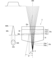
- FIG. 2 is a diagram illustrating an example of an optical system of the illumination device according to the first embodiment.
- FIG. 2 is a diagram illustrating an example of a configuration of an optical system viewed along a fast axis.
- FIG. 2 is a diagram illustrating an example of an optical system configuration viewed along the slow axis.
- 4 is a graph for explaining the shape of an aspheric surface of an aspheric lens.
- 1 is a graph for explaining the shape of an aspheric surface.
- FIG. 2 is a diagram illustrating an example of an intensity distribution of excitation light. 1 is a graph for explaining aspheric surface shapes corresponding to a plurality of Conic coefficients.
- FIG. 13 is a diagram illustrating an example of a configuration of an illumination device according to a second embodiment.
- FIG. 13 is a diagram illustrating an example of a configuration of an illumination device according to a third embodiment. 13 is an enlarged view illustrating a schematic view of a portion of another example of the light reducing structure. FIG. FIG. 13 is a diagram illustrating another example of the configuration of the lighting device according to the third embodiment.
- FIG. 2 is an enlarged view showing a configuration of a portion of the lighting device.
- the inventor has created a technology for reducing unevenness in illumination light in a lighting device.
- the following describes the first to fourth embodiments of the technology with reference to the drawings.
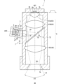
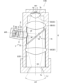
- FIG. 1 is a diagram showing an example of the configuration of the lighting device 1 according to the first embodiment.
- the lighting device 1 is a device that emits fluorescence L1 as illumination light to an external lighting space S1.
- the lighting space S1 is, for example, a space where a person can stay or pass through, and may be, for example, an indoor space of a specific building or a passage space connecting each room.
- the lighting device 1 is disposed, for example, on the ceiling of the lighting space S1.
- the fluorescence L1 emitted from the lighting device 1 can directly illuminate an object in the lighting space S1.
- directly means that the fluorescence L1 is irradiated to the object without passing through optical components such as a lens and a spatial light modulation unit.
- a person in the lighting space S1 can visually recognize the shape and color of the object illuminated by the fluorescence L1.
- the lighting device 1 includes a light source 2, an optical system 3, a wavelength conversion member 4, a wavelength separation filter 5, an optical system 6, and a housing 7.
- a light source 2 As shown in FIG. 1, the lighting device 1 includes a light source 2, an optical system 3, a wavelength conversion member 4, a wavelength separation filter 5, an optical system 6, and a housing 7.
- a wavelength conversion member 4 As shown in FIG. 1, the lighting device 1 includes a light source 2, an optical system 3, a wavelength conversion member 4, a wavelength separation filter 5, an optical system 6, and a housing 7.
- the housing 7 houses the light source 2, the optical system 3, the wavelength conversion member 4, the wavelength separation filter 5, and the optical system 6.
- the housing 7 includes a housing section 71 and a housing section 72.
- the housing section 71 houses the wavelength conversion member 4, the wavelength separation filter 5, and the optical system 6, and the housing section 72 houses the light source 2 and the optical system 3.
- the housing 7 has an exit opening (corresponding to a first opening) 7a.
- the exit opening 7a is formed at the end of the housing part 71. Fluorescence L1 as illumination light is emitted from the exit opening 7a to the illumination space S1.
- the exit opening 7a is a space that connects the internal space of the housing 7 and the illumination space S1.
- the exit opening 7a functions as an outlet for the fluorescence L1 from the internal space of the housing 7 to the illumination space S1.
- a lens does not have to be located inside the exit opening 7a.
- optical components such as a lens and a spatial light modulation unit do not have to be located forward of the exit opening 7a in the emission direction.
- the housing 71 has an elongated shape that is long in the first direction.
- the lighting device 1 is installed on the ceiling, the lighting device 1 is installed on the ceiling with the first direction aligned along the vertical direction.
- the light source 2, the optical system 3, and the wavelength separation filter 5 are aligned along the second direction that intersects with the first direction.
- the housing 72 is attached to the side of the housing 71, and the internal space of the housing 72 and the internal space of the housing 71 are connected to each other through an opening 74 formed in the side of the housing 71.
- the light source 2 emits excitation light L0 into the housing 7.
- the light source 2 has an emission portion (e.g., an emission surface) 201 that emits the excitation light L0.
- the excitation light L0 may be, for example, light having a peak in a wavelength range of 415 nm or less, more specifically, in a wavelength range of 380 nm or more and 415 nm or less.
- the excitation light L0 may be purple light having a peak near 405 nm.
- the excitation light L0 is not necessarily limited to purple light, and may be, for example, blue light having a peak near 450 nm.
- the intensity distribution of the excitation light L0 immediately after the light source 2 has, for example, a mountain-like shape.
- the intensity distribution here refers to the intensity distribution in a cross section perpendicular to the direction of light propagation.
- the intensity distribution of the excitation light L0 immediately after the light source 2 is the intensity distribution of the excitation light L0 in a cross section perpendicular to the optical axis AX0 of the light source 2.
- the intensity distribution of this excitation light L0 has, for example, a mountain-like shape in which the intensity in the center is higher than the intensity in the peripheral area.
- the intensity distribution has a single mountain-like shape with a single peak intensity.
- the intensity distribution of the excitation light L0 in a cross section immediately after the emission part 201 of the light source 2 is shown diagrammatically directly below the light source 2.
- the excitation light L0 from the light source 2 is incident on the wavelength conversion member 4 via the optical system 3, the wavelength separation filter 5, and the lenses 61B and 61A of the optical system 6, as described below.
- the optical system 3 can adjust the intensity distribution of the excitation light L0. Specifically, the optical system 3 flattens the intensity distribution of the excitation light L0.
- the optical system 3 includes an aspherical lens 31.
- the aspherical lens 31 can adjust the intensity distribution of the excitation light L0 by refracting each ray of the excitation light L0. As described in detail later, the aspherical lens 31 refracts each ray of the excitation light L0 so that the intensity distribution of the excitation light L0 on the wavelength conversion member 4 is flattened.
- the intensity distribution of the excitation light L0 on the wavelength conversion member 4 is shown diagrammatically to the right of the wavelength conversion member 4.
- the intensity distribution of the excitation light L0 on the wavelength conversion member 4 has a so-called top hat shape.
- the optical system 3 may further include a cylindrical lens 32.
- the cylindrical lens 32 can adjust the aspect ratio in the intensity distribution of the excitation light L0.
- the cylindrical lens 32 will be described in detail later.
- the excitation light L0 from the optical system 3 passes through the opening 74 and enters the wavelength separation filter 5.
- the wavelength separation filter 5 guides the excitation light L0 to the wavelength conversion member 4.
- the wavelength separation filter 5 reflects the excitation light L0 toward the wavelength conversion member 4 and guides the excitation light L0 to the wavelength conversion member 4.
- the excitation light L0 from the wavelength separation filter 5 enters the wavelength conversion member 4 via lenses 61B and 61A.
- the wavelength conversion member 4 contains a phosphor.
- the wavelength conversion member 4 emits fluorescence L1 based on the incident excitation light L0.
- the fluorescence L1 has a spectrum different from that of the excitation light L0. Specifically, the peak wavelength of the fluorescence L1 is longer than the peak wavelength of the excitation light L0, and the fluorescence L1 is visible light.
- the fluorescence L1 travels from the wavelength conversion member 4 toward the wavelength separation filter 5, and in the example of FIG. 1, it is incident on the wavelength separation filter 5 via lenses 61A and 61B.
- the wavelength separation filter 5 guides the fluorescence L1 to the emission opening 7a. In the example of FIG. 1, the wavelength conversion member 4, the wavelength separation filter 5, and the emission opening 7a are arranged in this order along the first direction, so the wavelength separation filter 5 transmits the fluorescence L1 from the wavelength conversion member 4 to the emission opening 7a side.
- the optical system 6 includes one or more lenses 61 located on the path of the fluorescence L1 between the wavelength conversion member 4 and the exit opening 7a.
- lenses 61A, 61B, and 61C are shown as the lenses 61.
- Lenses 61A to 61C are lined up between the wavelength conversion member 4 and the exit opening 7a.
- lenses 61A and 61B are located between the wavelength conversion member 4 and the wavelength separation filter 5.
- Lens 61A is located closer to the wavelength conversion member 4 than lens 61B.
- Lens 61C is located between the wavelength separation filter 5 and the exit opening 7a. Therefore, in the example of FIG. 1, the wavelength conversion member 4, lens 61A, lens 61B, wavelength separation filter 5, lens 61C, and exit opening 7a are arranged in this order along the first direction.
- the optical system 6 focuses the fluorescence L1 on a virtual image plane IS1 on the side of the exit opening 7a, while emitting it from the exit opening 7a at a predetermined light distribution angle ⁇ 2.
- the light distribution angle ⁇ 2 here is, for example, the spread angle of a portion of the fluorescence L1 that has half the peak intensity.
- the light distribution angle ⁇ 2 can also be called the half-value angle.
- the optical system 6 collects the fluorescence L1 on the side of the exit opening 7a, while emitting it from the exit opening 7a at a predetermined light distribution angle ⁇ 2.
- the optical system 6 forms an image of the fluorescence L1 in the wavelength conversion member 4 on a virtual image plane IS1
- the optical system 6 can also be said to be a so-called imaging optical system.
- the virtual image plane IS1 may be a flat surface or a curved surface. If the image plane IS1 is a curved surface, an inexpensive lens can be used as the lens 61 of the optical system 6.
- the lighting device 1 can emit the fluorescent light L1 into the illumination space S1. Moreover, this lighting device 1 includes an aspherical lens 31.
- the aspherical lens 31 refracts each ray of the excitation light L0 so as to flatten the intensity distribution of the excitation light L0 on the wavelength conversion member 4. Therefore, the excitation light L0 is more uniformly incident on the wavelength conversion member 4.
- the aspherical lens 31 causes excitation light L0 having a more uniform intensity distribution to be incident on the wavelength conversion member 4.
- excitation light L0 having a top-hat shaped intensity distribution is incident on the wavelength conversion member 4. This allows the wavelength conversion member 4 to emit fluorescence L1 more uniformly. Therefore, the lighting device 1 can emit fluorescence L1 into the illumination space S1 with less unevenness, and can realize a high-quality illumination space S1 with less glare.
- the lighting device 1 can emit the fluorescence L1 into the illumination space S1 with higher efficiency.
- the temperature of the central part of the wavelength conversion member 4 becomes high, which is likely to lead to thermal deterioration of the wavelength conversion member 4.
- excitation light L0 which has a lower peak intensity and a more uniform intensity distribution, is incident on the wavelength conversion member 4, so the degree of thermal deterioration of the wavelength conversion member 4 can be reduced.
- the intensity distribution of the excitation light L0 is flattened by the aspherical lens 31, more of the excitation light L0 can be incident on the wavelength conversion member 4.
- the intensity distribution of the excitation light L0 is flattened, but the excitation light L0 is scattered on the surface of the ground glass or at the boundaries between the lenses of the array lens, so the amount of excitation light L0 incident on the wavelength conversion member 4 decreases.
- the aspherical lens 31 can transmit more excitation light L0, so the amount of excitation light L0 incident on the wavelength conversion member 4 can be increased. In other words, the lighting device 1 can emit fluorescence L1 into the illumination space S1 more efficiently.
- the thickness of the aspherical lens 31 is not particularly large, the size of the lighting device 1 can be reduced compared to when a light-guiding member such as a rod lens is used.
- the above description is not intended to prohibit the lighting device 1 of this embodiment from including optical components such as frosted glass, an array lens, and a rod lens in addition to the aspheric lens 31.
- the light source 2 is, for example, a light emitting element such as a semiconductor laser element such as a laser diode (LD), a vertical cavity surface emitting laser (VCSEL), a light emitting diode (LED), and a super luminescent diode (SLD).
- the light source 2 may include a single light emitting element.
- the emission section 201 of the light source 2 may be an emission end of the light emitting element.
- the light emitting element may emit, for example, a 405 nm violet laser light.
- a gallium nitride (GaN) based semiconductor laser that emits the excitation light L0 may be used.
- the light source 2 can emit excitation light L0 having a mountain-shaped intensity distribution.
- the spread angle of the excitation light L0 emitted by the light source 2 on a first axis perpendicular to the optical axis AX0 is larger than the spread angle on a second axis perpendicular to the optical axis AX0 and the first axis (see also FIG. 2).
- the first axis can also be called the fast axis.
- the second axis can also be called the slow axis.
- the spread of the excitation light L0 on the slow axis is shown diagrammatically.
- Wavelength separation filter 5> 1 the wavelength separation filter 5 reflects the excitation light L0 toward the wavelength conversion member 4 and transmits the fluorescence L1 toward the exit opening 7a.
- the wavelength separation filter 5 is also called a dichroic mirror.
- the wavelength separation filter 5 includes, for example, a dielectric multilayer film 51 and a substrate 52.
- the substrate 52 is a transparent plate-like member.
- the substrate 52 is positioned such that its thickness direction intersects with the optical axis AX1 of the optical system 6 at approximately 45 degrees.
- the dielectric multilayer film 51 is formed on the substrate 52.
- the dielectric multilayer film 51 has a structure in which dielectric thin films are repeatedly laminated.
- the dielectric for example, one or more materials selected from silicon oxide (SiO 2 ), titanium oxide (TiO 2 ), aluminum oxide (Al 2 O 3 ), zirconium oxide (ZrO 2 ), tantalum oxide (Ta 2 O 5 ), and niobium oxide (Nb 2 O 3 ) are used.
- SiO 2 silicon oxide
- TiO 2 titanium oxide
- Al 2 O 3 aluminum oxide
- ZrO 2 zirconium oxide
- tantalum oxide Ta 2 O 5
- niobium oxide Nb 2 O 3
- the wavelength conversion member 4 includes a phosphor.
- the wavelength conversion member 4 may include, for example, BaMgAl10O17 :Eu, (Sr,Ca,Ba) 10 ( PO4 ) 6Cl2 :Eu, (Sr,Ba) 10 ( PO4 ) 6Cl2 :Eu , etc. as a wavelength conversion material (i.e., a fluorescent material) that converts the excitation light L0 into blue light.
- the wavelength conversion member 4 may include, for example, (Sr,Ba,Ca) 5 ( PO4 ) 3Cl :Eu , Sr4Al14O25 :Eu, etc.
- the wavelength conversion member 4 may contain, for example, SrSi2 (O,Cl) 2N2 :Eu, (Sr,Ba,Mg) 2SiO4 : Eu2 + , or ZnS:Cu,Al, Zn2SiO4 :Mn, etc. as a wavelength conversion material that converts the excitation light L0 to green light.
- the wavelength conversion member 4 may contain, for example, Y2O2S :Eu, Y2O3 :Eu, SrCaClAlSiN3 : Eu2 + , CaAlSiN3 :Eu, or CaAlSi(ON) 3 :Eu, etc. as a wavelength conversion material that converts the excitation light L0 to red light.
- the wavelength conversion member 4 may contain 3Ga5O12 :Cr, etc. as a wavelength conversion material that converts the excitation light L0 to light having a wavelength in the near - infrared region. If the wavelength conversion member 4 contains multiple types of wavelength converting materials corresponding to multiple colors of light, the wavelength conversion member 4 can emit fluorescence L1 with high color rendering.
- the excitation light L0 is light having a peak at 380 nm to 415 nm and the wavelength conversion member 4 contains phosphors corresponding to red, green, and blue light, the color rendering of the fluorescence L1 can be particularly improved.
- the wavelength conversion member 4 may also contain a resin such as a binder to connect the phosphor particles together.
- the lenses 61 are formed of a material containing at least one of glass, such as optical glass, and resin, such as acrylic resin, for example. As shown in FIG 1, each lens 61 may be a biconvex lens.
- the lens 61 is not limited to a convex lens, but may be a concave lens or a meniscus lens.
- the lens 61 may be a spherical lens or an aspherical lens.
- the optical system 6 forms an image of the object plane on a virtual image plane IS1. That is, in the example of FIG. 1, three lenses 61 can constitute an imaging optical system.
- the surface 4a of the wavelength conversion member 4 has a conjugate relationship with the image plane IS1. Note that the conjugate relationship mentioned here does not have a strict meaning, and the part on the exit opening 7a side where the fluorescence L1 is most concentrated (the part where the size of the fluorescence L1 is smallest in the cross section perpendicular to the optical axis AX1 of the optical system 6) can be considered to be the image plane IS1.
- the image plane IS1 may be located, for example, at the exit opening 7a.
- the fluorescence L1 is collected at the image plane IS1 and is emitted through the exit opening 7a into the illumination space S1.
- the image plane IS1 does not necessarily have to be located inside the exit opening 7a.
- the image plane IS1 may be located slightly offset from the exit opening 7a in the direction of travel of the fluorescence L1 passing through the exit opening 7a. In other words, the image plane IS1 may be located slightly inside the housing 7 relative to the exit opening 7a, or slightly toward the illumination space S1.
- the lens 61A located closest to the wavelength conversion member 4 is a convex lens. Therefore, the lens 61A can guide the fluorescence L1, which has a large divergence angle and is emitted from the wavelength conversion member 4, to the subsequent lens 61B at a smaller divergence angle.
- the lens 61B is also a convex lens. Therefore, the lens 61B can guide the fluorescence L1, which diverges from the lens 61A, to the wavelength separation filter 5 while further reducing the divergence angle.
- the lens 61B may refract the fluorescence L1 so that the fluorescence L1 passes through the wavelength separation filter 5 in a state closer to parallel light.
- the lens 61C focuses the fluorescence L1 that has passed through the wavelength separation filter 5 on the side of the exit opening 7a, and emits it from the exit opening 7a at a predetermined light distribution angle ⁇ 2.
- the optical system 6 reduces the cross-sectional size (e.g., light diameter) of the fluorescence L1 at the image plane IS1, making it less likely for the fluorescence L1 to be reflected or scattered by the inner wall of the exit opening 7a of the housing 7, realizing a more uniform, high-quality illumination space S1 with less glare.
- the presence of the illumination device 1 when viewed from outside the exit opening 7a can be reduced.
- FIGS. 2 and 3 are diagrams showing an example of the configuration of the optical system 3.
- FIG. 2 shows a configuration of the optical system 3.
- FIG. 3 shows an example of the configuration of the optical system 3 as viewed along the slow axis.
- the aspherical lens 31 is formed of a material including at least one of glass such as optical glass and resin such as acrylic resin.
- the aspherical lens 31 has an aspherical surface 31a and a surface 31b opposite to the aspherical surface 31a.
- the surface 31b is the surface of the aspherical lens 31 facing the light source 2
- the aspherical surface 31a is the surface of the aspherical lens 31 facing the light source 2.
- the aspherical surface 31a has a concave shape.
- the aspherical surface 31a may have a shape that is rotationally symmetric about the optical axis AX0.
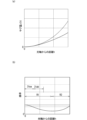
- FIG. 4 is a graph for explaining the shape of the aspheric surface 31a of the aspheric lens 31.
- FIG. 4(a) shows the amount of sag z(h) at each position on the aspheric surface 31a
- FIG. 4(b) shows the curvature at each position on the aspheric surface 31a.
- the horizontal axis shows the distance h from the optical axis AX0.
- the vertical axis shows the amount of sag z(h)
- the vertical axis shows the curvature.
- the graph in FIG. 4(a) shows the relationship between the sag amount z(h) and the distance h, and therefore shows the shape of the aspheric surface 31a itself in a cross section including the optical axis AX0.
- the aspheric surface 31a may have a shape that follows, for example, one of the curves of a hyperbola.
- the aspheric surface 31a may have a shape that follows one of the hyperbolic surfaces of a two-leaf hyperboloid.
- a dashed line is used to show a graph of a sphere having the same curvature as the curvature at the center of the aspheric surface 31a.
- the curvature of a circle is constant regardless of the distance h.
- the curvature in a predetermined circular region R1 including the center of the aspheric surface 31a, gradually decreases as the distance h increases. That is, the curvature monotonically decreases in the circular region R1.
- the predetermined circular region R1 may be, for example, a region that is concentric with the aspheric surface 31a and is about 50% or less of the diameter of the aspheric surface 31a, in other words, a region that is about 50% or less of the effective diameter of the aspheric lens 31.
- the curvature increases slightly and gradually as the distance h increases.
- the curvature has a minimum value at the boundary position between the circular region R1 and the annular region R2.
- the maximum value of the curvature may be more than twice, more than 5 times, more than 10 times, or more than 20 times the minimum value of the curvature.
- Figure 5 is also a graph for explaining the shape of aspheric surface 31a.
- Figure 5(a) is a graph showing the relationship between the angle ⁇ (see also Figures 2 and 3) between the surface normal and the optical axis AX0 at each position within aspheric surface 31a and the distance h.
- Figure 5(b) is a graph showing the relationship between the first-order differential value of angle ⁇ with respect to distance h and the distance h.
- Figure 5(c) is a graph showing the relationship between the second-order differential value of angle ⁇ with respect to distance h and the distance h. Note that, for reference, Figure 5 also shows a graph of a spherical surface having the same curvature as the curvature at the center of aspheric surface 31a by a dashed line.
- the first derivative of the angle ⁇ for the spherical surface increases monotonically with increasing distance h.
- the first derivative of the angle ⁇ for the aspheric surface 31a gradually decreases as the distance h increases, approximately within the circular region R1.
- the first derivative of the angle ⁇ decreases monotonically in the circular region R1.
- the first derivative of the angle ⁇ increases slightly and gradually with increasing distance h, approximately within the annular region R2.
- the maximum value of the first derivative of the angle ⁇ may be at least twice, at least five times, at least ten times, or at least twenty times the minimum value.
- the second derivative of the angle ⁇ for the spherical surface also increases monotonically with increasing distance h.
- the second derivative of the angle ⁇ for the aspheric surface 31a decreases once with increasing distance h, reaches a minimum value (local minimum value), and then increases.
- the graph showing the relationship between the second derivative of the angle ⁇ and the distance h has a local minimum value. More specifically, the graph showing the relationship between the second derivative of the angle ⁇ and the distance h has a local minimum value in a region that is 30% or less of the effective diameter of the aspheric lens 31.
- the second derivative of the angle ⁇ for the spherical surface is positive regardless of the distance h
- the second derivative of the angle ⁇ for the aspheric surface 31a is negative in the entire region that is 30% or less of the effective diameter of the aspheric lens 31.
- excitation light L0 is incident on the aspheric surface 31a of the aspheric lens 31.
- the intensity distribution of the excitation light L0 immediately before it is incident on the aspheric surface 31a is shown typically to the left of the aspheric surface 31a, and the cross-sectional shape of the excitation light L0 is shown typically below the intensity distribution.
- the central light of the excitation light L0 is referred to as central light L0a.
- the central light L0a is a portion of the excitation light L0 whose intensity is, for example, 50% or more of the peak intensity.
- the light of the excitation light L0 that is outside the central light L0a is referred to as peripheral light L0b.
- the peripheral light L0b is a portion of the excitation light L0 whose intensity is, for example, less than 50% of the peak intensity.
- the first central portion 31aa is the portion of the aspheric surface 31a that is closer to the optical axis AX0 than the first non-central portion 31ab.
- the first central portion 31aa is, for example, a region within the circular region R1 (see also FIG. 4(b)). That is, the outer peripheral edge of the first central portion 31aa is, for example, located within the circular region R1.
- the outer peripheral edge of the first central portion 31aa is also the boundary between the first central portion 31aa and the first non-central portion 31ab.
- the first non-central portion 31ab may also be a region within the circular region R1 (see also FIG. 4(b)). That is, the outer peripheral edge of the first non-central portion 31ab may also be located within the circular region R1.
- the curvature at each position of the first central portion 31aa and the first non-central portion 31ab monotonically decreases as it moves from the center to the outside.
- the curvature of the first central portion 31aa is greater than the curvature of the first non-central portion 31ab.
- the average value of the curvature of the first central portion 31aa is greater than the average value of the curvature of the first non-central portion 31ab.
- the minimum value of the curvature of the first central portion 31aa may be greater than the maximum value of the curvature of the first non-central portion 31ab.
- the central light L0a is refracted at the first central portion 31aa with a larger refractive power (see also FIG. 2). Therefore, the spread angle of the central light L0a that passes through the aspherical lens 31 increases. In other words, the central light L0a spreads more as it passes through the aspherical lens 31. Here, the spread angle of the central light L0a increases more as it is closer to the center.
- the curvature of the first non-central portion 31ab is relatively small, the peripheral light L0b is refracted at the first non-central portion 31ab with a smaller refractive power.
- the spread angle of the peripheral light L0b does not increase much compared to the increase in the spread angle of the central light L0a.
- the peripheral light L0b does not spread much as it passes. Therefore, the density of the central light becomes relatively smaller as it moves away from the aspherical lens 31, and the density of the peripheral light becomes relatively larger as it moves away from the aspherical lens 31.
- the width of the central light L0a whose intensity is 50% or more of the peak intensity, becomes relatively wider as it moves away from the aspheric lens 31, and the width of the peripheral light L0b, whose intensity is less than 50% of the peak intensity, becomes relatively narrower. In other words, the intensity distribution becomes flatter.
- the excitation light L0 from the aspherical lens 31 passes through the cylindrical lens 32, the wavelength separation filter 5, the lens 61B, and the lens 61A in this order, and enters the wavelength conversion member 4.
- the shape of the aspherical surface 31a of the aspherical lens 31 can be designed so that the intensity distribution of the excitation light L0 on the surface 4a of the wavelength conversion member 4 has a top hat shape (in other words, a trapezoidal shape).
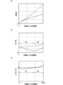
- Figure 6 is a diagram showing an example of the intensity distribution of the excitation light L0.
- Figure 6(a) shows an example of the intensity distribution of the excitation light L0 immediately after the light source 2.
- Figure 6(a) shows an example of the intensity distribution of the excitation light L0 between the light source 2 and the optical system 3.
- Figure 6(b) shows an example of the intensity distribution of the excitation light L0 in the wavelength conversion member 4. Note that in Figure 6(b), the intensity distribution of the excitation light L0 immediately after the light source 2 is shown by a two-dot chain line.
- the intensity distribution of the excitation light L0 immediately after the light source 2 has a single mountain-shaped shape.
- the width of the region where the intensity is 90% or more of the peak intensity is referred to as the first width D1
- the width of the region where the intensity is 50% or more of the peak intensity is referred to as the second width D2.
- the ratio of the first width D1 to the second width D2 may be, for example, 0.5 or less.
- the intensity distribution of the excitation light L0 in the wavelength conversion member 4 has a top hat shape.
- the intensity distribution has a single trapezoid shape.
- the ratio of the first width D1 to the second width D2 may be 0.7 or more.
- the aspheric lens 31 refracts the excitation light L0 having a ratio of 0.5 or less, thereby causing the excitation light L0 having a ratio of 0.7 or more to be incident on the surface 4a of the wavelength conversion member 4.
- the shape of the aspheric surface 31a may be expressed by the following formula.
- z(h) indicates the amount of sag
- k indicates the Conic coefficient
- R0 indicates the radius of curvature at the center of the aspheric surface 31a
- An (n is an even number) indicates the coefficient of the higher order term.
- FIG. 7 is a graph for explaining the shape of the aspheric surface 31a corresponding to each of a plurality of conic coefficients k.
- FIG. 7(a) is a graph showing the relationship between the sag amount z(h) of the aspheric surface 31a and the distance h
- FIG. 7(b) is a graph showing the relationship between the second derivative of the angle ⁇ and the distance h.
- Graphs Gz1 to Gz7 are shown in FIG. 7(a).
- Graphs Gz1 to Gz7 show the relationship between the sag amount z(h) and the distance h when the conic coefficient k is 0, -1, -5, -10, -20, -40, and -60, respectively.
- Graphs G ⁇ 1 to G ⁇ 7 are shown in FIG. 7(b).
- Graphs G ⁇ 1 to G ⁇ 7 show the relationship between the second derivative of the angle ⁇ and the distance h when the conic coefficient k is 0, -1, -5, -10, -20, -40, and -60, respectively.
- the minimum value of the graph showing the relationship between the second derivative of the angle ⁇ and the distance h is indicated by a hollow circle.
- the smaller the Conic coefficient k the smaller the curvature of the outer periphery of the aspheric surface 31a.
- the curvature of the aspheric surface 31a gradually becomes smaller toward the outer periphery, and in a cross section including the optical axis AX0, the outer periphery of the aspheric surface 31a approaches a straight line shape.
- the outer periphery of the aspheric surface 31a approaches the shape of the side of a cone.
- the curvature of the central part of the aspheric surface 31a does not become much smaller than that of the outer periphery even if the Conic coefficient k becomes smaller.
- the aspheric lens 31 can effectively reduce the increase in the spread angle of the peripheral light L0b of the excitation light L0 while maintaining the effect of increasing the spread angle of the central light L0a of the excitation light L0. As a result, the aspheric lens 31 can more appropriately flatten the intensity distribution of the excitation light L0.
- the Conic coefficient k may be, for example, -60 or more and -3 or less. This allows the aspheric lens 31 to more appropriately flatten the intensity distribution of the excitation light L0 in which the ratio of the first width D1 to the second width D2 is 0.5 or less. Furthermore, the Conic coefficient k may be -60 or more and -10 or less, -60 or more and -20 or less, or -45 or more and -35 or less. The narrower the range that is applied among the above ranges, the more appropriately the aspheric lens 31 can flatten the intensity distribution of the excitation light L0.
- the excitation light L0 is incident on a range of 30% or less of the effective diameter of the aspherical surface 31a of the aspherical lens 31.
- the aspherical lens 31 can further appropriately flatten the intensity distribution.
- the smaller the Conic coefficient k the closer the position of the minimum value is to the center of the aspheric surface 31a. Also, the smaller the Conic coefficient k, the smaller the minimum value. As can be seen from FIG. 7(b), the minimum value may be 30% or less of the effective diameter of the aspheric lens 31, or it may be 25% or less. In this case, the Conic coefficient k is -3 or less.
- the excitation light L0 transmitted through the aspherical lens 31 spreads as it travels towards lens 61B, is refracted by the convex lenses 61B and 61A, and is focused on the wavelength conversion member 4.
- the aspherical surface 31a of the concave aspherical lens 31 can increase the cross-sectional size of the excitation light L0 incident on lens 61B. This allows the excitation light L0 to be incident on the surface 4a of the wavelength conversion member 4 over a sufficiently sized incident area. Therefore, the wavelength conversion member 4 can emit fluorescence L1 over a wider range.
- the surface 31b of the aspherical lens 31 has a convex shape.
- the surface 31b may have a shape that is rotationally symmetric about the optical axis AX0.
- the aspherical surface 31a has a concave shape, and the surface 31b on the opposite side has a convex shape, so that the aspherical lens 31 is a so-called meniscus lens. Since the surface 31b of the aspherical lens 31 has a convex shape, the surface 31b can refract the excitation light L0 so that the spread angle of the excitation light L0 is reduced.
- the concave aspherical surface 31a of the aspherical lens 31 increases the spread angle of the excitation light L0, but the convex surface 31b reduces the spread angle of the excitation light L0. Therefore, the amount of change in the spread angle of the excitation light L0 due to transmission through the aspherical lens 31 can be reduced. This can reduce the possibility that the incidence area of the excitation light L0 will unnecessarily spread on the surface 4a of the wavelength conversion member 4 away from the optical system 3.
- the surface 31b of the aspherical lens 31 may be spherical or aspherical.
- the curvature of the second central portion 31ba of the surface 31b may be greater than the curvature of the second non-central portion 31bb of the surface 31b.
- the curvature of the surface 31b may monotonically decrease from the center toward the outside in a region including both the second central portion 31ba and the second non-central portion 31bb.
- the surface 31b may have a shape along a hyperbolic surface.
- the central light L0a of the excitation light L0 may be incident on the second central portion 31ba
- the peripheral light L0b of the excitation light L0 may be incident on the second non-central portion 31bb.
- the shape of surface 31b may be the same as that of aspheric surface 31a.
- a graph showing the relationship between the second derivative of angle ⁇ and distance h for surface 31b may have a minimum value.
- the minimum value may be located within a region that is 30% or less of the effective diameter of aspheric lens 31.
- the Conic coefficient k may be within the above-mentioned range.
- the central light L0a is refracted at surface 31b so that its spread angle becomes smaller, and the peripheral light L0b is refracted at surface 31b so that its spread angle is not reduced as much as that of the central light L0a. Therefore, the central light L0a can be incident on an area of the aspheric surface 31a with a larger curvature. In other words, since the curvature of the aspheric surface 31a is larger toward the center, the central light L0a is incident on the first central portion 31aa with a larger curvature. Therefore, the aspheric surface 31a can refract the more intense central light L0a at the first central portion 31aa with a larger curvature, and the spread angle of the central light L0a can be made larger. Therefore, the central light L0a of the excitation light L0 can be broadened further, and the intensity distribution can be made flatter.
- Cylindrical lens 32> 1 to 3 the optical system 3 further includes a cylindrical lens 32.
- the cylindrical lens 32 is formed of a material including at least one of glass such as optical glass and resin such as acrylic resin. In the example of FIG. 1, the cylindrical lens 32 is located between the aspheric lens 31 and the wavelength separation filter 5.
- the cylindrical lens 32 adjusts the aspect ratio of the cross-sectional shape of the excitation light L0.
- the cylindrical lens 32 can adjust the ratio between the width of the excitation light L0 on the fast axis and the width of the excitation light L0 on the slow axis.
- the width of the light may be, for example, the width of a region having an intensity equal to or greater than half e of the peak intensity.
- "e” is called the Napier's number.
- the cylindrical lens 32 may adjust the aspect ratio of the excitation light L0, for example, so that the aspect ratio of the cross-sectional shape of the excitation light L0 on the surface 4a of the wavelength conversion member 4 approaches the aspect ratio of the surface 4a of the wavelength conversion member 4.
- the cylindrical lens 32 is a convex-plano lens. That is, the cylindrical lens 32 has a convex surface 32a and a flat surface 32b.
- the flat surface 32b is located on the light source 2 side with respect to the convex surface 32a.
- the flat surface 32b is located on the aspheric lens 31 side with respect to the convex surface 32a.
- the convex surface 32a may be spherical.
- the cylindrical lens 32 is located with its power direction along the fast axis. According to this, in a cross section parallel to the slow axis and the optical axis AX0 (see FIG.
- the spread angle of the excitation light L0 hardly changes before and after the cylindrical lens 32, and in a cross section parallel to the fast axis and the optical axis AX0 (see FIG. 3), the spread angle of the excitation light L0 is reduced by the cylindrical lens 32. Therefore, the difference between the fast axis and the slow axis of the spread angle of the excitation light L0 transmitted through the cylindrical lens 32 can be reduced. Therefore, the aspect ratio of the cross-sectional shape of the excitation light L0 approaches 1 as it moves away from the cylindrical lens 32.
- the aspherical lens 31 and the cylindrical lens 32 may be in contact with each other.
- the outer periphery 31ac of the aspherical surface 31a of the aspherical lens 31 may be a plane perpendicular to the optical axis AX0.
- the outer periphery 31ac may be a portion located outside the first non-central portion 31ab, and may be a portion on which the excitation light L0 is not incident.
- the outer periphery 31ac of the aspherical lens 31 may be in contact with the plane 32b of the cylindrical lens 32, or may be bonded to the plane 32b of the cylindrical lens 32. This makes it easy to position the aspherical lens 31 relative to the cylindrical lens 32.
- the illumination device 1 may include a holder 721 that integrally holds the optical system 3.
- the holder 721 integrally holds the aspherical lens 31 and the cylindrical lens 32, and is attached to the housing 72.
- the holder 721 may, for example, clamp the outer peripheries of the aspherical lens 31 and the cylindrical lens 32 in a direction along the optical axis AX0.
- the holder 721 may be part of the housing part 72.
- FIG. 8 is a diagram showing an example of the configuration of the lighting device 1 according to the second embodiment.
- the lighting device 1 according to the second embodiment is referred to as lighting device 1A.
- the lighting device 1A differs from the lighting device 1 according to the first embodiment in terms of the position of the optical element.
- the light source 2, the optical system 3, the wavelength separation filter 5, the lens 61B, the lens 61A, and the wavelength conversion member 4 are arranged in this order in the second direction, and the wavelength separation filter 5 and the exit opening 7a are arranged in this order in the first direction intersecting with the second direction.
- the first direction and the second direction are orthogonal to each other.
- the excitation light L0 from the light source 2 is incident on the optical system 3.
- the optical system 3 adjusts the intensity distribution of the excitation light L0 as described below.
- the excitation light L0 from the optical system 3 is incident on the wavelength separation filter 5.
- the wavelength separation filter 5 transmits the excitation light L0 and guides it to the wavelength conversion member 4.
- the excitation light L0 is transmitted through lenses 61B and 61A of the optical system 6 and is incident on the wavelength conversion member 4.
- the optical system 3 includes an aspherical lens 31.
- the aspherical lens 31 refracts each ray of the excitation light L0 to flatten the intensity distribution of the excitation light L0.
- the aspherical lens 31 refracts the excitation light L0 so that the intensity distribution of the excitation light L0 in the wavelength conversion member 4 has a top hat shape.
- more uniform excitation light L0 is incident on the wavelength conversion member 4, and the wavelength conversion member 4 can emit fluorescence L1 more uniformly.
- the fluorescence L1 from the wavelength conversion member 4 passes through lenses 61A and 61B and enters the wavelength separation filter 5.
- the wavelength separation filter 5 reflects the fluorescence L1 and guides it to the exit opening 7a.
- the optical system 6 is located on the path of the fluorescence L1 from the wavelength conversion member 4 to the exit opening 7a, and emits the fluorescence L1 from the exit opening 7a at a predetermined light distribution angle while forming an image of the fluorescence L1 on a virtual image plane IS1 on the exit opening 7a side.
- the optical system 6 includes one or more lenses 61 located on the path. In the example of FIG. 8, multiple lenses 61 are located, and more specifically, three lenses 61A to 61C are located as the multiple lenses 61. Lenses 61A and 61B are located between the wavelength conversion member 4 and the wavelength separation filter 5. Lens 61A is located on the wavelength conversion member 4 side relative to lens 61B. Lens 61C is located between the wavelength separation filter 5 and the exit opening 7a.
- the aspherical lens 31 flattens the intensity distribution of the excitation light L0. This allows the lighting device 1A to emit fluorescence L1 with less unevenness into the lighting space S1.
- the wavelength conversion member 4, lens 61A, lens 61B, wavelength separation filter 5, optical system 3 and light source 2 are aligned along the second direction, and the wavelength separation filter 5 and lens 61C are aligned in the first direction. This reduces the number of optical components aligned along the first direction, allowing the size of the lighting device 1A in the first direction to be reduced. Therefore, even if the height of the space above the ceiling is low, the lighting device 1A can be easily installed in the space.
- the aspherical lens 31 is a biconvex lens. In other words, both the aspherical surface 31a and the opposite surface 31b of the aspherical lens 31 have a convex shape. In the example of Fig. 8, the aspherical surface 31a is located closer to the light source 2 than the surface 31b. The surface 31b may be spherical.
- FIG. 9 is a diagram for explaining the shape of the aspherical surface 31a of the aspherical lens 31. Note that in the example of FIG. 9, the aspherical surface 31a is located on the opposite side to the light source 2, but even if the aspherical surface 31a is located on the light source 2 side, the principle of flattening the intensity distribution by the aspherical lens 31 is the same.
- the excitation light L0 is refracted at the aspheric surface 31a. Since the aspheric surface 31a has a convex shape, the spread angle of the excitation light L0 is reduced by passing through the aspheric lens 31. In the example of FIG. 9, the excitation light L0 that passes through the aspheric lens 31 narrows as it advances and is focused at the focusing portion BW1. In other words, the excitation light L0 has a focusing portion (i.e., the focusing portion BW1). Then, the excitation light L0 advances while expanding again in front of the focusing portion BW1. Explaining based on FIG.
- the focusing portion BW1 is located between the aspheric lens 31 and the wavelength conversion member 4, and as a more specific example, it is located between the aspheric lens 31 and the lens 61B.
- the focusing portion BW1 may be located between the aspheric lens 31 and the wavelength separation filter 5, may be located on the wavelength separation filter 5, or may be located between the wavelength separation filter 5 and the lens 61B.
- FIG. 10 is a graph for explaining the shape of the aspheric surface 31a of the aspheric lens 31.
- FIG. 10(a) shows the sag amount z(h) at each position on the aspheric surface 31a
- FIG. 10(b) shows the curvature at each position on the aspheric surface 31a.
- FIG. 10 also shows a graph of a spherical surface having the same curvature as the curvature at the center of the aspheric surface 31a by a dashed line.
- the curvature in a predetermined circular region R1 including the center of the aspherical surface 31a, gradually decreases as the distance h increases. That is, the curvature monotonically decreases in the circular region R1.
- the diameter of the circular region R1 is about 60% of the effective diameter of the aspherical lens 31.
- the curvature gradually increases as the distance h increases in the annular region R2 located outside the circular region R1 of the aspherical surface 31a. That is, the curvature has a minimum value at the boundary position between the circular region R1 and the annular region R2.
- the maximum value of the curvature may be more than twice the minimum value of the curvature.
- FIG. 11 is also a graph for explaining the shape of aspheric surface 31a.
- FIG. 11(a) is a graph showing the relationship between angle ⁇ and distance h.
- FIG. 11(b) is a graph showing the relationship between the first derivative of angle ⁇ with respect to distance h and distance h.
- FIG. 11(c) is a graph showing the relationship between the second derivative of angle ⁇ with respect to distance h and distance h.
- the dashed line also shows a graph for a spherical surface having the same curvature as the curvature at the center of aspheric surface 31a.
- the first derivative of the angle ⁇ for the spherical surface increases monotonically with increasing distance h.
- the first derivative of the angle ⁇ for the aspheric surface 31a gradually decreases as the distance h increases, approximately within the circular region R1.
- the first derivative of the angle ⁇ decreases monotonically in the circular region R1.
- the first derivative of the angle ⁇ gradually increases slightly with increasing distance h, approximately within the annular region R2.
- the maximum value of the first derivative of the angle ⁇ may be more than twice the minimum value of the curvature.
- the second derivative of the angle ⁇ for the spherical surface also increases monotonically with increasing distance h.
- the second derivative of the angle ⁇ for the aspheric surface 31a decreases once with increasing distance h, reaches a minimum value (local minimum value), and then increases.
- the graph showing the relationship between the second derivative of the angle ⁇ and the distance h has a local minimum value. More specifically, the graph showing the relationship between the second derivative of the angle ⁇ and the distance h has a local minimum value in a region that is 30% or less of the effective diameter of the aspheric lens 31.
- the second derivative of the angle ⁇ for the spherical surface is positive regardless of the distance h, the second derivative of the angle ⁇ is negative in the entire region that is 30% or less of the effective diameter of the aspheric lens 31.
- excitation light L0 is incident on the aspheric surface 31a of the aspheric lens 31.
- the intensity distribution of the excitation light L0 immediately before it is incident on the aspheric surface 31a is shown diagrammatically below the aspheric lens 31, and the cross-sectional shape of the excitation light L0 is shown diagrammatically to the right of the intensity distribution.
- the central light L0a is incident on the first central portion 31aa of the aspheric surface 31a
- the peripheral light L0b is incident on the first non-central portion 31ab of the aspheric surface 31a.
- the first central portion 31aa is, for example, a region within the circular region R1 (see also FIG. 10(b)). That is, the outer peripheral edge of the first central portion 31aa is, for example, located within the circular region R1.
- the first non-central portion 31ab may also be a region within the circular region R1 (see also FIG. 10(b)). That is, the outer peripheral edge of the first non-central portion 31ab may also be located within the circular region R1.
- the curvature at each position on the first central portion 31aa and the first non-central portion 31ab monotonically decreases as it moves from the center to the outside.
- the curvature of the first central portion 31aa is greater than the curvature of the first non-central portion 31ab.
- the average value of the curvature of the first central portion 31aa is greater than the average value of the curvature of the first non-central portion 31ab.
- the minimum value of the curvature of the first central portion 31aa may be greater than the maximum value of the curvature of the first non-central portion 31ab.
- the central light L0a is refracted with a greater refractive power. Therefore, the central light L0a is focused at a position closer to the aspherical lens 31 and travels while spreading out forward of the focusing position.
- the closer to the center the light ray of the central light L0a is, the greater the refractive power it is refracted with. Therefore, the closer to the center the light ray is, the closer to the center it is focused at a position closer to the aspherical lens 31.
- the two central light rays that are focused at the position closest to the aspherical lens 31 are shown by dashed lines.
- the peripheral light L0b is refracted with a smaller refractive power.
- the peripheral light L0b is focused at a position farther from the aspherical lens 31 and advances while spreading out forward from the focusing position.
- the light rays of the peripheral light L0b closer to the outer periphery are refracted with a smaller refractive power.
- the light rays closer to the outer periphery are focused at a position farther from the aspherical lens 31.
- the two peripheral light rays that are focused at the position farthest from the aspherical lens 31 are shown by dashed lines.
- the density of the light beams closer to the center decreases at a position forward of the focusing part BW1. Conversely, the density of the light beams closer to the periphery increases. In other words, the width of the central light L0a, whose intensity is 50% or more of the peak intensity, becomes relatively wider as it moves forward from the focusing part BW1, and the width of the peripheral light L0b, whose intensity is less than 50% of the peak intensity, becomes relatively narrower. Therefore, the intensity distribution becomes flatter.
- the excitation light L0 from the aspherical lens 31 passes through the wavelength separation filter 5, lens 61B, and lens 61A in that order, and enters the wavelength conversion member 4.
- the shape of the aspherical surface 31a of the aspherical lens 31 can be designed so that the intensity distribution of the excitation light L0 on the surface 4a of the wavelength conversion member 4 has a top hat shape.
- the Conic coefficient k which is one of the indices that indicate the shape of the aspheric surface 31a of the aspheric lens 31, may be -60 or more and -3 or less, as in the first embodiment. This allows the aspheric lens 31 to more appropriately flatten the intensity distribution of the excitation light L0 in which the ratio of the first width D1 to the second width D2 is 0.5 or less. Furthermore, the Conic coefficient k may be -60 or more and -10 or less, -60 or more and -20 or less, or -45 or more and -35 or less.
- the excitation light L0 advances while spreading out in front of the focusing section BW1. Therefore, the excitation light L0 can be sufficiently spread out just before the lens 61B, and even if the excitation light L0 is reduced in size by the convex lenses 61A and 61B, it can be incident on the surface 4a of the wavelength conversion member 4 over a sufficiently large incident area.
- the aspherical lens 31 focuses the excitation light L0 at the focusing portion BW1, and therefore has a large refractive power.
- the radius of curvature R0 at the center of the aspherical surface 31a is larger than the radius of curvature R0 of the aspherical surface 31a according to the first embodiment.
- the cylindrical lens 32 is positioned between the light source 2 and the aspherical lens 31.
- the cylindrical lens 32 refracts the excitation light L0 so that the aspect ratio of the excitation light L0 approaches 1.
- the aspect ratio of the excitation light L0 immediately after the cylindrical lens 32 is closer to 1 than the aspect ratio of the excitation light L0 immediately before the cylindrical lens 32. Therefore, the excitation light L0 can be made to enter the aspherical lens 31 with the difference between the fast axis width and the slow axis width of the excitation light L0 reduced.
- the aspect ratio of the cross-sectional shape of the excitation light L0 entering the aspherical lens 31 is close to 1.
- the aspheric lens 31 can more appropriately flatten the intensity distribution on both the fast axis and the slow axis.
- FIG. 12 is a diagram for explaining another example of the aspherical surface 31a of the aspherical lens 31.
- the aspherical surface 31a also has a convex shape, so the spread angle of the excitation light L0 is reduced by transmission through the aspherical lens 31.
- the excitation light L0 transmitted through the aspherical lens 31 advances while narrowing.
- the excitation light L0 is incident on the surface 4a of the wavelength conversion member 4 before the focusing part where the light diameter is smallest.
- the excitation light L0 does not have the focusing part BW1 between the aspherical lens 31 and the wavelength conversion member 4.
- the curvature of the first central portion 31aa of the aspheric surface 31a is smaller than the curvature of the first non-central portion 31ab.
- the curvature of the aspheric surface 31a may monotonically increase from the center toward the outside in the region including the first central portion 31aa and the first non-central portion 31ab.
- the central light L0a is refracted with a smaller refractive power.
- the central light L0a is focused at a position farther from the aspherical lens 31.
- the closer to the center a ray of light is, the farther from the aspherical lens 31 it is focused at.
- the two central light rays that are focused at the position farthest from the aspherical lens 31 are shown by dashed lines, and the virtual focusing position Pa of the two light rays is shown diagrammatically.
- the peripheral light L0b is refracted with a greater refractive power.
- the peripheral light L0b is focused at a position closer to the aspherical lens 31.
- the closer a ray of the peripheral light L0b is to the periphery the greater the refractive power it is refracted with.
- the closer a ray is to the periphery the closer it is to the aspherical lens 31 it is focused at a position closer to the aspherical lens 31.
- the two peripheral light rays that are focused at the position closest to the aspherical lens 31 are shown by dashed lines, and the virtual focusing position Pb of the two light rays is shown diagrammatically.
- the density of light rays closer to the center is relatively small between the aspherical lens 31 and the focusing position Pb.
- the density of light rays closer to the periphery is high.
- the width of the central light L0a whose intensity is 50% or more of the peak intensity, becomes relatively wider toward the front of the aspherical lens 31, and the width of the peripheral light L0b, whose intensity is less than 50% of the peak intensity, becomes relatively narrower. Therefore, the intensity distribution becomes flatter.
- the excitation light L0 from the aspherical lens 31 passes through the wavelength separation filter 5, lens 61B, and lens 61A in that order, and enters the wavelength conversion member 4.
- the shape of the aspherical surface 31a of the aspherical lens 31 can be designed so that the intensity distribution of the excitation light L0 on the surface 4a of the wavelength conversion member 4 has a top hat shape.
- shape of the aspherical surface 31a of the aspherical lens 31 in the second embodiment can be applied to the first embodiment, and the shape of the aspherical surface 31a of the aspherical lens 31 in the first embodiment can be applied to the second embodiment.
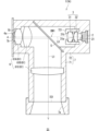
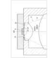
- FIG. 13 is a diagram showing an example of the configuration of the illumination device 1 according to the third embodiment.
- the illumination device 1 in FIG. 13 is referred to as illumination device 1B.
- the illumination device 1B differs from the illumination device 1 according to the first embodiment in the presence or absence of a light reducing structure 8.
- the light reducing structure 8 is located on at least a part of the inner wall of the housing 7. More specifically, the light reducing structure 8 is located on at least a part of the inner wall of the housing part 71.
- the housing part 71 includes a cylindrical part 73 surrounding the path of the fluorescence L1.
- the cylindrical part 73 houses the lens 61A, the lens 61B, the wavelength separation filter 5, and the lens 61C.
- An exit opening 7a is formed at the end of the cylindrical part 73.
- an opening 74 is formed on the side of the cylindrical part 73 for the excitation light L0 from the light source 2 to pass through.
- the light reducing structure 8 is located on at least a part of the inner wall of the cylindrical portion 73, and as a more specific example, it is located on the inner wall of the cylindrical portion 73 between the lens 61B and the wavelength separation filter 5, between the wavelength separation filter 5 and the lens 61C, and between the lens 61C and the exit opening 7a.
- the light reducing structure 8 does not have to be located between the lens 61A and the lens 61B on the inner wall of the cylindrical portion 73.
- the light reducing structure 8 may be formed on the entire circumference of the inner wall of the cylindrical portion 73.
- the "entire circumference" here refers to the entire circumference of the inner wall in a cross section perpendicular to the optical axis AX1.
- the light reduction structure 8 reduces the possibility that the unwanted light will be emitted from the emission opening 7a into the illumination space S1.
- the light reduction structure 8 includes, for example, a reflection reduction section 81.
- the reflection reduction section 81 may include an absorbing film having a high absorptivity for the fluorescence L1.
- the absorptivity may be, for example, 50% or more, 60% or more, 80% or more, or 90% or more.
- the reflection reduction section 81 may have a high absorptivity for the entire wavelength range of the fluorescence L1, or may have a high absorptivity for the peak wavelength.
- the absorptivity of the reflection reduction section 81 for the fluorescence L1 is higher than the absorptivity of the inner wall of the housing section 71 where the light reduction structure 8 is not located.
- Such a reflection reduction section 81 can be formed, for example, by performing a blackening process on the inner wall of the housing section 71.
- the reflection reduction section 81 is formed on the inner wall of the housing section 71 by a blackening process such as chemical conversion treatment, plating, and painting.
- a blackening process such as chemical conversion treatment, plating, and painting.
- a matte blackening process or a glossy blackening process may be adopted.
- Such a reflection reduction section 81 is made of a black material.
- the material includes, for example, at least one of a black metal, a black metal oxide film, and a black resin.
- the reflection reduction portion 81 may include a dielectric multilayer film.
- the dielectric multilayer film has, for example, a structure in which a plurality of dielectric thin films are stacked.
- the dielectric for example, one or more materials selected from titanium oxide (TiO 2 ), SiO 2 , niobium pentoxide (Nb 2 O 5 ), tantalum pentoxide (Ta 2 O 5 ), and magnesium fluoride (MgF 2 ) are used.
- Such a dielectric multilayer film may also be called a low reflection film or an anti-reflection film.
- the reflection reduction section 81 may include flocked paper.
- the flocked paper may be composed of a base material such as paper or cloth, and synthetic fibers attached in an upright position to the base material. If black flocked paper is used, it is possible to further reduce the reflection of unwanted light compared to flocked paper of other colors.
- lighting device 1B for example, when unwanted light obtained by reflection and scattering of fluorescence L1 in the optical system 6 travels toward the reflection reduction section 81 on the inner wall of the cylindrical section 73, it is incident on the reflection reduction section 81. Since the reflection reduction section 81 reduces the reflection of unwanted light, it is possible to reduce the unwanted light that is emitted from the emission opening 7a. Therefore, lighting device 1B can emit high-quality fluorescence L1 with even less unevenness into the illumination space S1.
- FIG. 14 is an enlarged view showing a schematic portion of another example of the light reduction structure 8.
- the light reduction structure 8 includes an uneven shape 82.
- the uneven shape 82 is, for example, the shape of the inner wall surface of the cylindrical portion 73, and FIG. 14 shows a schematic portion of the uneven shape 82.
- the uneven shape 82 has unevenness in the optical axis direction parallel to the optical axis AX1.
- the uneven shape 82 has a shape in which concave and convex portions are arranged alternately in a cross section including the optical axis AX1.
- the uneven shape 82 has a sawtooth shape, and each tooth of the sawtooth (i.e., the convex portion) is formed by a first surface 821 on the wavelength conversion member 4 side and a second surface 822 on the emission opening 7a side.
- the first surfaces 821 and the second surfaces 822 are alternately continuous.
- Such an uneven shape 82 may have a helical shape similar to a female screw, or may have a shape in which multiple ring shapes are arranged in the optical axis direction.
- the pitch of the uneven shape 82 is set to, for example, about several mm or less.
- the length of the second surface 822 which moves away from the optical axis AX1 toward the exit opening 7a, may be longer than that of the first surface 821.
- the angle that the second surface 822 makes with respect to the optical axis AX1 may be smaller than the angle that the first surface 821 makes with respect to the optical axis AX1.
- the first surface 821 is nearly perpendicular to the optical axis AX1, so that in a cross section including the optical axis AX1, the first surface 821 corresponds to the adjacent side of a right triangle and corresponds to the hypotenuse of the right triangle of the second surface 822.
- Unwanted light is incident on the inner wall surface of the cylindrical section 73 in an oblique direction, mainly from the wavelength conversion member 4 side.
- the first surface 821 reflects and scatters the incident unwanted light mainly toward the opposite side to the emission opening 7a. In other words, the first surface 821 reflects and scatters the unwanted light mainly in an oblique direction toward the wavelength conversion member 4 side.
- some of the unwanted light from the first surface 821 may be incident on the second surface 822, since the second surface 822 is inclined, most of the unwanted light can be reflected and scattered in an oblique direction toward the wavelength conversion member 4 side.
- the unwanted light reflected and scattered by the second surface 822 is incident on the first surface 821, where it is reflected and scattered in an oblique direction toward the wavelength conversion member 4 side.
- the unwanted light that is incident on the uneven shape 82 from the wavelength conversion member 4 side can be mainly reflected and scattered in an oblique direction toward the wavelength conversion member 4 side. This increases the number of times the unwanted light is reflected and scattered within the housing 7, and the unwanted light can be attenuated within the housing 7. Therefore, the possibility of unwanted light being emitted from the exit opening 7a can be reduced.
- FIG. 15 is a diagram showing a schematic diagram of another example of the configuration of the lighting device 1 according to the third embodiment.
- the lighting device 1 in FIG. 15 is referred to as lighting device 1C.
- the lighting device 1C differs from the lighting device 1A in the presence or absence of a light reduction structure 8.
- the light reduction structure 8 is located on at least a part of the inner wall of the housing 7. More specifically, the light reduction structure 8 is located on at least a part of the inner wall of the housing part 71.
- the housing part 71 includes a cylindrical part 711 that houses the lens 61A and the lens 61B, a connecting part 712 that houses the wavelength separation filter 5, and a cylindrical part 713 that houses the lens 61C.
- An emission opening 7a is formed at the end of the cylindrical part 713 opposite the connecting part 712.
- the light reduction structure 8 is located on at least a part of the inner walls of the cylindrical portion 711 and the cylindrical portion 713.
- the light reduction structure 8 is located on the inner wall of the cylindrical portion 711 between the lens 61B and the wavelength separation filter 5, on the inner wall of the cylindrical portion 713 between the wavelength separation filter 5 and the lens 61C, and between the lens 61C and the exit opening 7a.
- the light reduction structure 8 does not have to be located between the lens 61A and the lens 61B on the inner wall of the cylindrical portion 711.
- the light reduction structure 8 may be formed on the entire circumference of the inner walls of the cylindrical portion 711 and the cylindrical portion 713.
- a reflection reduction portion 81 or an uneven shape 82 may be applied to the light reduction structure 8.
- this lighting device 1C can also reduce the possibility of unwanted light being emitted from the exit opening 7a.
- FIG. 16 is an enlarged view of a portion of the configuration of the illumination device 1.
- an opening 70 is located between the wavelength conversion member 4 and the optical system 6 in the path of the fluorescence L1.
- the opening 70 has a second opening (hereinafter referred to as the diaphragm opening) 7b.
- the diaphragm opening 7b of the opening 70 passes the light of the fluorescence L1 having a divergence angle of a predetermined divergence angle ⁇ 1 or less to the optical system 6 side.
- the shielded light light that travels at a divergence angle larger than the divergence angle ⁇ 1 of the fluorescence L1 is blocked by the opening 70.
- the opening 70 may be a part of the housing 7.
- the surface area of the wavelength conversion member 4 as viewed along the optical axis direction parallel to the optical axis AX1 may be smaller than the minimum opening area of the aperture 7b of the opening 70. This allows a larger portion of the fluorescence L1 that spreads out and travels from the wavelength conversion member 4 to pass through the aperture 7b.
- the angle ⁇ 1 that defines the numerical aperture of the optical system 6 may be equal to or greater than the spread angle ⁇ 1 of the fluorescence L1 that passes through the diaphragm aperture 7b.
- the numerical aperture is the product of the sine of the half-value of the angle ⁇ 1 and the refractive index.
- the angle ⁇ 1 is, for example, the angle formed by both outer rays of virtual light that can pass through the effective area of the optical system 6.
- the effective area here corresponds to the area through which light passes through which the optical performance of the optical system 6 can be exhibited, and for example, the effective area of the lens 61A is the area of the lens 61A excluding a predetermined peripheral width.
- the effective area of the lens 61A may be the area surrounded by the inner peripheral edge of the part of the housing 7 that holds the peripheral edge of the lens 61A (for example, the lens holder).
- the spread angle ⁇ 1 and the angle ⁇ 1 are equal to each other.
- the lighting device 1 can emit high-quality fluorescence L1 with even less glare into the lighting space S1.
- the lighting devices 1, 1A to 1C have been described in detail, but the above description is merely an example in all respects, and the lighting devices 1, 1A to 1C are not limited thereto. It is understood that countless variations not illustrated can be imagined without departing from the scope of this disclosure.
- the configurations described in the above embodiments and variations (or aspects) can be combined or omitted as appropriate, as long as they are not mutually contradictory.
- lenses such as lens 61A and lens 61B may not be positioned between the wavelength conversion member 4 and the wavelength separation filter 5.
- aspheric lens 31 may be positioned between the wavelength conversion member 4 and the wavelength separation filter 5.
- fluorescence L1 from the wavelength conversion member 4 passes through the aspheric lens 31 and enters the wavelength separation filter 5.
- the wavelength separation filter 5 does not necessarily have to be a dichroic mirror.
- the wavelength separation filter 5 may be a dichroic prism.
- This disclosure includes the following:
- the lighting device is a lighting device that emits illumination light into an external illumination space, and can include a housing having a first opening that opens into the illumination space, a light source that emits excitation light into the interior of the housing, an aspherical lens located inside the housing, into which the excitation light from the light source is incident and that flattens the intensity distribution of the excitation light, a wavelength conversion member located inside the housing, into which the excitation light from the aspherical lens is incident and that emits fluorescence as the illumination light having a spectrum different from that of the excitation light based on the excitation light, and a wavelength separation filter located inside the housing, which guides the excitation light from the aspherical lens to the wavelength conversion member and guides the fluorescence from the wavelength conversion member to the first opening.
- the aspherical surface of the aspherical lens may have a concave shape, and the curvature of a first central portion of the aspherical surface on the central side may be greater than the curvature of a first non-central portion of the aspherical surface that is located outside the first central portion.
- the surface of the aspherical lens opposite the aspherical surface may have a convex shape.
- the curvature of a second central portion of the opposite surface of the aspheric lens may be greater than the curvature of a second non-central portion of the opposite surface that is located outside the second central portion.
- the aspherical surface of the aspherical lens may have a convex shape, and the curvature of a first central portion of the aspherical surface may be smaller than the curvature of a first non-central portion of the aspherical surface that is located outside the first central portion.
- the aspherical surface of the aspherical lens may have a convex shape, the curvature of a first central portion of the aspherical surface may be greater than the curvature of a first non-central portion of the aspherical surface that is located outside the first central portion, and the excitation light from the aspherical lens may have a portion that is focused between the aspherical lens and the wavelength conversion member.
- a central light having an intensity of 50% or more of the peak intensity can be incident on the first central portion of the aspherical lens, and peripheral light on the outer periphery side of the central light can be incident on the first non-central portion of the aspherical lens.
- a graph showing the relationship between the second derivative of the angle between the surface normal at a position on the aspheric surface of the aspheric lens and the optical axis of the aspheric lens with respect to the distance between the optical axis and the position and the distance can have a minimum value.
- the graph can have the minimum value at least in a region that is 30% or less of the effective diameter of the aspherical lens.
- the Conic coefficient indicating the aspheric shape of the aspheric lens may be greater than or equal to -60 and less than or equal to -3.
- the ratio of a first width of a region having an intensity of 50% or more of the peak intensity to a second width of a region having an intensity of 90% or more of the peak intensity may be 0.7 or more.
- any one of the illumination devices (1) to (11) above may further include a cylindrical lens positioned between the light source and the wavelength separation filter to adjust the aspect ratio of the cross-sectional shape of the excitation light.
- the cylindrical lens can be positioned between the light source and the aspherical lens.
- the lighting device of (12) or (13) above may further include a holder that holds the cylindrical lens and the aspherical lens together.
- the peak wavelength of the excitation light may be 415 nm or less, and the wavelength conversion member may include multiple types of phosphors.
- the light source may include a semiconductor laser element.
- a light reducing structure may be located on the inner wall of the housing to absorb unwanted light generated by reflection or scattering of the fluorescence, or to reflect or scatter the unwanted light toward the wavelength conversion member.
- any one of the lighting devices (1) to (17) above may include an optical system that is located on the path of the fluorescence from the wavelength conversion member to the first opening and that focuses the fluorescence on a virtual image plane on the first opening side.
- the lighting device of (18) above may further include an opening having a second opening that passes the fluorescence from the wavelength conversion member with a predetermined spread angle or less toward the optical system and blocks the fluorescence with a larger spread angle than the predetermined spread angle, and the angle that defines the numerical aperture of the optical system may be equal to or greater than the predetermined spread angle.
- the optical system includes a plurality of lenses positioned on the path.
Landscapes
- Engineering & Computer Science (AREA)
- General Engineering & Computer Science (AREA)
- Physics & Mathematics (AREA)
- Spectroscopy & Molecular Physics (AREA)
- Lenses (AREA)
Abstract
照明装置は、筐体と、光源と、非球面レンズと、波長変換部材と、波長分離フィルタとを備える。筐体は、照明空間に開口する第1開口を有する。光源は励起光を筐体の内部に出射する。非球面レンズは筐体の内部に位置しており、光源から入射された励起光の強度分布を平坦化させる。波長変換部材は、筐体の内部に位置しており、励起光と異なるスペクトルを有する照明光としての蛍光を、励起光に基づいて発する。波長分離フィルタは、筐体の内部に位置しており、非球面レンズからの励起光を波長変換部材に導き、波長変換部材からの蛍光を第1開口に導く。
Description
本出願は、日本国出願2022-168283号(2022年10月20日出願)の優先権を主張するものであり、当該出願の開示全体を、ここに参照のために取り込む。
本開示は、照明装置に関する。
従来から、光源と、波長変換素子と、光源からの光を波長変換素子に反射させ、かつ、波長変換素子からの光を透過させる光学部品とを含む装置が提案されている(例えば特許文献1)。
照明装置が開示される。
一実施形態において、照明装置は、外部の照明空間に照明光を出射する。照明装置は、筐体と、光源と、非球面レンズと、波長変換部材と、波長分離フィルタとを備える。筐体は、照明空間に開口する第1開口を有する。光源は、励起光を筐体の内部に出射する。非球面レンズは、筐体の内部に位置している。非球面レンズには、光源から励起光が入射する。非球面レンズは励起光の強度分布を平坦化させる。波長変換部材は筐体の内部に位置している。波長変換部材には、非球面レンズからの励起光が入射する。波長変換部材は、励起光と異なるスペクトルを有する照明光としての蛍光を、励起光に基づいて発する。波長分離フィルタは筐体の内部に位置しており、非球面レンズからの励起光を波長変換部材に導き、波長変換部材からの蛍光を第1開口に導く。
発明者は、照明装置において、照明光のムラを低減させる技術を創出した。これについて、以下、第1実施形態から第4実施形態を図面に基づいて説明する。
<1.第1実施形態>
<1-1.照明装置1の概略構成>
図1は、第1実施形態にかかる照明装置1の構成の一例を概略的に示す図である。図1で示されるように、照明装置1は、照明光としての蛍光L1を外部の照明空間S1に出射させる装置である。照明空間S1は、例えば人が滞在もしくは通過し得る空間であり、より具体的な一例として所定の建造物の室内空間、もしくは、各室内をつなぐ通路空間であってもよい。照明装置1は例えば照明空間S1の天井部に配置される。照明装置1から出射された蛍光L1は、照明空間S1内の物体を直接に照らすことができる。ここでいう「直接」とは、蛍光L1がレンズおよび空間光変調部等の光学部品を経由せずに、物体に照射されることをいう。照明空間S1内の人は、蛍光L1によって照らされた物体の形状および色を視認することができる。ムラの少ないより均一な蛍光L1が物体に照射されることにより、人は物体の形状および色をより適切に視認することができる。
図1で示されるように、照明装置1は、光源2と、光学系3と、波長変換部材4と、波長分離フィルタ5と、光学系6と、筐体7とを含んでいる。以下では、まず、各構成の一例について概説し、その後、詳述する。
筐体7は、光源2、光学系3、波長変換部材4、波長分離フィルタ5および光学系6を収納している。図1の例では、筐体7は筐体部71および筐体部72を含んでいる。筐体部71は波長変換部材4、波長分離フィルタ5および光学系6を収納し、筐体部72は光源2および光学系3を収納している。
筐体7は、出射開口(第1開口に相当)7aを有している。図1の例では、出射開口7aは筐体部71の端部に形成されている。照明光としての蛍光L1は出射開口7aから照明空間S1に出射する。出射開口7aは、筐体7の内部空間と照明空間S1とをつなぐ空間である。出射開口7aは、筐体7の内部空間から照明空間S1への蛍光L1用の出口として機能する。図1で例示されるように、出射開口7aの内部にはレンズが位置していなくてもよい。また出射開口7aよりも出射方向の前方には、レンズおよび空間光変調部等の光学部品は位置していなくてもよい。
図1の例では、波長変換部材4、波長分離フィルタ5、光学系6および出射開口7aは第1方向に沿って並んでいる。よって、筐体部71は、第1方向に長い長尺状の形状を有している。照明装置1が天井部に設置される場合、照明装置1は第1方向が鉛直方向に沿う姿勢で天井部に設置される。図1の例では、光源2、光学系3および波長分離フィルタ5は、第1方向に交差する第2方向に沿って並んでいる。図1の例では、筐体部72は筐体部71の側部に取り付けられており、筐体部72の内部空間および筐体部71の内部空間は、筐体部71の側部に形成された開口74を通じて互いに繋がっている。
光源2は励起光L0を筐体7の内部に出射する。図1で示されるように、光源2は、励起光L0を出射する出射部(例えば出射面)201を有する。励起光L0は、例えば、415nm以下の波長範囲、より具体的には380nm以上かつ415nm以下の波長範囲内にピークを持つ光であってもよい。さらに具体的な一例として、励起光L0は、405nm近傍にピークを有する紫色の光であってもよい。なお、励起光L0は必ずしも紫色の光に限らず、例えば、450nm近傍にピークを有する青色の光であってもよい。
光源2の直後における励起光L0の強度分布は、例えば、山状形状を有する。ここでいう強度分布とは、光の進行方向に直交する断面における強度分布である。つまり、光源2の直後の励起光L0の強度分布は、光源2の光軸AX0に直交する断面における励起光L0の強度分布である。この励起光L0の強度分布は、例えば、その中央部の強度が周縁部の強度よりも高い山状の形状を有する。より具体的な一例として、該強度分布は、単一のピーク強度を有する単一の山状の形状を有する。図1の例では、光源2の出射部201の直後の断面における励起光L0の強度分布が、光源2の直下において模式的に示されている。
光源2からの励起光L0は、後述のように、光学系3、波長分離フィルタ5、光学系6のレンズ61Bおよびレンズ61Aを経由して波長変換部材4に入射する。
光学系3は励起光L0の強度分布を調整することができる。具体的には、光学系3は励起光L0の強度分布を平坦化させる。光学系3は非球面レンズ31を含む。非球面レンズ31は、励起光L0の各光線を屈折させることにより、励起光L0の強度分布を調整することができる。非球面レンズ31は、後に詳述するように、波長変換部材4上の励起光L0の強度分布が平坦化するように、励起光L0の各光線を屈折させる。図1の例では、波長変換部材4上の励起光L0の強度分布が波長変換部材4の右側において模式的に示されている。図1の例では、波長変換部材4上の励起光L0の強度分布は、いわゆるトップハット形状を有している。
図1で示されるように、光学系3はシリンドリカルレンズ32をさらに含んでいてもよい。シリンドリカルレンズ32は、励起光L0の強度分布における縦横比を調整することができる。シリンドリカルレンズ32についても後に詳述する。
光学系3からの励起光L0は開口74を通過して波長分離フィルタ5に入射する。波長分離フィルタ5は励起光L0を波長変換部材4に導く。図1の例では、波長分離フィルタ5は励起光L0を波長変換部材4側に反射させて、励起光L0を波長変換部材4に導く。図1の例では、波長分離フィルタ5からの励起光L0はレンズ61Bおよびレンズ61Aを経由して波長変換部材4に入射する。
波長変換部材4は蛍光体を含んでいる。波長変換部材4は、入射した励起光L0に基づいて蛍光L1を発する。蛍光L1は、励起光L0のスペクトルとは異なるスペクトルを有する。具体的には、蛍光L1のピーク波長は励起光L0のピーク波長よりも長く、蛍光L1は可視光である。蛍光L1は波長変換部材4から波長分離フィルタ5へ向かって進み、図1の例では、レンズ61Aおよびレンズ61Bを経由して波長分離フィルタ5に入射する。波長分離フィルタ5は蛍光L1を出射開口7aに導く。図1の例では、波長変換部材4、波長分離フィルタ5および出射開口7aは第1方向に沿ってこの順で並んでいるので、波長分離フィルタ5は波長変換部材4からの蛍光L1を出射開口7a側に透過させる。
光学系6は、波長変換部材4と出射開口7aとの間の蛍光L1の経路上に位置する1つ以上のレンズ61を含む。図1の例では、レンズ61として、レンズ61A、レンズ61Bおよびレンズ61Cが示されている。レンズ61Aからレンズ61Cは波長変換部材4と出射開口7aとの間で並んでいる。図1の例では、レンズ61Aおよびレンズ61Bは波長変換部材4と波長分離フィルタ5との間に位置している。レンズ61Aはレンズ61Bよりも波長変換部材4側に位置する。レンズ61Cは波長分離フィルタ5と出射開口7aとの間に位置している。よって、図1の例では、波長変換部材4、レンズ61A、レンズ61B、波長分離フィルタ5、レンズ61Cおよび出射開口7aは第1方向に沿ってこの順で配列されている。
光学系6は、蛍光L1を出射開口7a側の仮想的な像面IS1で結像させつつ、所定の配光角φ2で出射開口7aから出射させる。ここでいう配光角φ2は、例えば、蛍光L1のうちピーク強度の半分の強度を有する部分の広がり角である。配光角φ2は半値角とも呼ばれ得る。要するに、光学系6は蛍光L1を出射開口7a側で集光させつつ、出射開口7aから所定の配光角φ2で出射させている。
光学系6は、波長変換部材4における蛍光L1の像を仮想的な像面IS1に形成するので、光学系6はいわゆる結像光学系であるともいえる。仮想的な像面IS1は平面であってもよく、湾曲面であってもよい。像面IS1が湾曲面である場合には、光学系6のレンズ61として安価なレンズを採用することができる。
以上のように、照明装置1は蛍光L1を照明空間S1に出射することができる。しかも、この照明装置1は非球面レンズ31を含んでいる。非球面レンズ31は波長変換部材4上の励起光L0の強度分布を平坦化させるように、励起光L0の各光線を屈折させる。このため、波長変換部材4にはより均一に励起光L0が入射する。
比較のために、波長変換部材4に山状の強度分布を有する励起光L0が入射した比較構造について説明する。波長変換部材4は励起光L0の強度に応じた強度で蛍光L1を発するので、その中央部でより高い強度で蛍光L1を発し、その周縁部でより低い強度で蛍光L1を発する。このため、照明装置1から出射した蛍光L1の強度分布のばらつき(ムラ)が大きくなる。
これに対して、本実施の形態では、非球面レンズ31によって、より均一な強度分布を有する励起光L0が波長変換部材4に入射する。例えば、トップハット形状の強度分布を有する励起光L0が波長変換部材4に入射する。このため、波長変換部材4はより均一に蛍光L1を発することができる。よって、照明装置1はより小さいムラで蛍光L1を照明空間S1に出射させることができ、グレアの少ない高品質な照明空間S1を実現することができる。
また、全体の光量がトップハット状の強度分布を有する励起光L0と同じであれば、山状の強度分布を有する励起光L0のピーク強度は比較的に高い。このため、波長変換部材4の中央部分から発する蛍光L1は飽和する可能性もある。この場合、該中央部分では、励起光L0の強度を十分に活用することができない。これに対して、本実施の形態では、ピーク強度の低い、より均一な強度分布を有する励起光L0が波長変換部材4に入射するので、蛍光L1の飽和も低減させることができる。したがって、照明装置1はより高い効率で蛍光L1を照明空間S1に出射させることができる。
また、山状の強度分布を有する励起光L0のピーク強度は高いので、波長変換部材4の中央部分の温度が高くなり、波長変換部材4の熱劣化を招きやすい。これに対して、本実施の形態では、ピーク強度の低い、より均一な強度分布を有する励起光L0が波長変換部材4に入射するので、波長変換部材4の熱劣化の程度を低減させることができる。
また、非球面レンズ31によって励起光L0の強度分布を平坦化させているので、励起光L0をより多く波長変換部材4に入射させることができる。例えば、非球面レンズ31に代わりに擦りガラスまたはアレイレンズを用いた場合、励起光L0の強度分布は平坦化するものの、励起光L0が擦りガラスの表面またはアレイレンズのレンズどうしの境界で散乱するので、波長変換部材4に入射する励起光L0の光量は低下してしまう。これに対して、非球面レンズ31はより多くの励起光L0を透過させることができるので、波長変換部材4に入射する励起光L0の光量を増加させることができる。つまり、照明装置1はさらに効率的に蛍光L1を照明空間S1に出射させることができる。
また、非球面レンズ31の厚みはさほど大きくないので、例えばロッドレンズなどの導光部材を用いる場合に比べて、照明装置1のサイズを低減させることもできる。
なお、上述の説明は、本実施の形態の照明装置1が非球面レンズ31に加えて、擦りガラス、アレイレンズおよびロッドレンズなどの光学部品を含むことを禁止する趣旨ではない。
以下、照明装置1の各構成の一例の詳細について説明する。
<1-2.光源2>
光源2は、例えば、レーザーダイオード(laser diode:LD)などの半導体レーザ素子、VCSEL(Vertical Cavity Surface Emitting LASER)、発光ダイオード(light Emitting diode:LED)およびSLD(super luminescent diode)などの発光素子を含んでもよい。光源2は単一の発光素子を含み得る。光源2の出射部201は、発光素子の出射端であってもよい。該発光素子には、例えば、405nmの紫色のレーザ光を励起光L0として放出する窒化ガリウム(GaN)系の半導体レーザが適用されてもよい。
光源2は、例えば、レーザーダイオード(laser diode:LD)などの半導体レーザ素子、VCSEL(Vertical Cavity Surface Emitting LASER)、発光ダイオード(light Emitting diode:LED)およびSLD(super luminescent diode)などの発光素子を含んでもよい。光源2は単一の発光素子を含み得る。光源2の出射部201は、発光素子の出射端であってもよい。該発光素子には、例えば、405nmの紫色のレーザ光を励起光L0として放出する窒化ガリウム(GaN)系の半導体レーザが適用されてもよい。
光源2は、山状の強度分布を有する励起光L0を出射し得る。また、ここでは、光源2が出射する励起光L0の、光軸AX0に直交する第1軸における広がり角は、光軸AX0および第1軸に直交する第2軸における広がり角よりも大きい(図2も参照)。第1軸はファスト軸とも呼ばれ得る。第2軸はスロー軸とも呼ばれ得る。図1の例では、スロー軸における励起光L0の広がりが模式的に示されている。
<1-3.波長分離フィルタ5>
図1の例では、波長分離フィルタ5は励起光L0を波長変換部材4に向けて反射させ、蛍光L1を出射開口7a側に透過させる。波長分離フィルタ5はダイクロイックミラーとも呼ばれる。
図1の例では、波長分離フィルタ5は励起光L0を波長変換部材4に向けて反射させ、蛍光L1を出射開口7a側に透過させる。波長分離フィルタ5はダイクロイックミラーとも呼ばれる。
波長分離フィルタ5は例えば誘電体多層膜51と基材52とを含む。基材52は透明な板状部材である。基材52は、その厚み方向が光学系6の光軸AX1に対して約45度で交差する姿勢で位置している。誘電体多層膜51は基材52上に形成されている。
例えば誘電体多層膜51は、誘電体の薄膜が複数回繰り返して積層された構造を有する。誘電体としては、例えば、酸化ケイ素(SiO2)、酸化チタン(TiO2)、酸化アルミニウム(Al2O3)、酸化ジルコニウム(ZrO2)、酸化タンタル(Ta2O5)および酸化ニオブ(Nb2O3)のうちの1つ以上の材料が採用される。例えば、誘電体多層膜51を構成する複数の誘電体の薄膜の膜厚を適宜設定することで、誘電体多層膜51における励起光L0を反射し、かつ、蛍光L1を透過させる分光透過率が実現され得る。つまり、波長分離フィルタ5の機能は実質的に誘電体多層膜51によって実現される。
<1-4.波長変換部材4>
波長変換部材4は蛍光体を含んでいる。波長変換部材4は、励起光L0を青色の光に変換する波長変換材料(つまり、蛍光材料)として、例えば、BaMgAl10O17:Eu、または、(Sr,Ca,Ba)10(PO4)6Cl2:Eu,(Sr,Ba)10(PO4)6Cl2:Eu等を含んでよい。波長変換部材4は、励起光L0を青緑色の光に変換する波長変換材料として、例えば、(Sr,Ba,Ca)5(PO4)3Cl:Eu,Sr4Al14O25:Eu等を含んでよい。波長変換部材4は、励起光L0を緑色の光に変換する波長変換材料として、例えば、SrSi2(O,Cl)2N2:Eu、(Sr,Ba,Mg)2SiO4:Eu2+、または、ZnS:Cu,Al、Zn2SiO4:Mn等を含んでよい。波長変換部材4は、励起光L0を赤色の光に変換する波長変換材料として、例えば、Y2O2S:Eu、Y2O3:Eu、SrCaClAlSiN3:Eu2+、CaAlSiN3:Eu、または、CaAlSi(ON)3:Eu等を含んでよい。波長変換部材4は、励起光L0を近赤外領域の波長を有する光に変換する波長変換材料として、3Ga5O12:Cr等を含んでよい。波長変換部材4が、複数色の光に対応した複数種類の波長変換材料を含んでいれば、波長変換部材4は、演色性の高い蛍光L1を発することができる。具体的には、励起光L0が380nmから415nmにピークを有する光であって、波長変換部材4が赤緑青の光に対応した蛍光体を有している場合は、蛍光L1の演色性を特に高めることができる。
波長変換部材4は蛍光体を含んでいる。波長変換部材4は、励起光L0を青色の光に変換する波長変換材料(つまり、蛍光材料)として、例えば、BaMgAl10O17:Eu、または、(Sr,Ca,Ba)10(PO4)6Cl2:Eu,(Sr,Ba)10(PO4)6Cl2:Eu等を含んでよい。波長変換部材4は、励起光L0を青緑色の光に変換する波長変換材料として、例えば、(Sr,Ba,Ca)5(PO4)3Cl:Eu,Sr4Al14O25:Eu等を含んでよい。波長変換部材4は、励起光L0を緑色の光に変換する波長変換材料として、例えば、SrSi2(O,Cl)2N2:Eu、(Sr,Ba,Mg)2SiO4:Eu2+、または、ZnS:Cu,Al、Zn2SiO4:Mn等を含んでよい。波長変換部材4は、励起光L0を赤色の光に変換する波長変換材料として、例えば、Y2O2S:Eu、Y2O3:Eu、SrCaClAlSiN3:Eu2+、CaAlSiN3:Eu、または、CaAlSi(ON)3:Eu等を含んでよい。波長変換部材4は、励起光L0を近赤外領域の波長を有する光に変換する波長変換材料として、3Ga5O12:Cr等を含んでよい。波長変換部材4が、複数色の光に対応した複数種類の波長変換材料を含んでいれば、波長変換部材4は、演色性の高い蛍光L1を発することができる。具体的には、励起光L0が380nmから415nmにピークを有する光であって、波長変換部材4が赤緑青の光に対応した蛍光体を有している場合は、蛍光L1の演色性を特に高めることができる。
また、波長変換部材4は、蛍光体の微粒子どうしを連結するためのバインダなどの樹脂を含んでいてもよい。
<1-5.光学系6>
レンズ61は、例えば、光学ガラス等のガラスおよびアクリル樹脂等の樹脂の少なくともいずれか一方を含む材料によって形成される。図1で示されるように、各レンズ61は両凸レンズであってもよい。なお、レンズ61は凸レンズに限らず、凹レンズもしくはメニスカスレンズであってもよい。また、レンズ61は球面レンズであってもよく、非球面レンズであってもよい。
レンズ61は、例えば、光学ガラス等のガラスおよびアクリル樹脂等の樹脂の少なくともいずれか一方を含む材料によって形成される。図1で示されるように、各レンズ61は両凸レンズであってもよい。なお、レンズ61は凸レンズに限らず、凹レンズもしくはメニスカスレンズであってもよい。また、レンズ61は球面レンズであってもよく、非球面レンズであってもよい。
光学系6は、波長変換部材4のうちのレンズ61A側の表面4aを物体面としたときに、該物体面の像を仮想的な像面IS1に形成させる。つまり、図1の例では、3つのレンズ61が結像光学系を構成し得る。照明装置1において、波長変換部材4の表面4aは像面IS1に対して共役関係を有している。なお、ここでいう共役関係とは厳密な意味でなく、出射開口7a側において、蛍光L1が最も集光された部分(光学系6の光軸AX1に垂直な断面における蛍光L1の大きさが最も小さい部分)を像面IS1と見なすことができる。
像面IS1は、例えば、出射開口7aに位置していてもよい。蛍光L1は像面IS1で集光しつつ、出射開口7aを通じて、照明空間S1に出射される。なお、像面IS1は必ずしも出射開口7aの内部に位置する必要はない。像面IS1は出射開口7aを通過する蛍光L1の進行方向において、出射開口7aからわずかにずれていて位置してもよい。つまり、像面IS1は出射開口7aよりもわずかに筐体7の内部側に位置していてもよく、わずかに照明空間S1側に位置していてもよい。
図1の例では、波長変換部材4の最も近くに位置するレンズ61Aは凸レンズである。このため、レンズ61Aは、波長変換部材4から発せられた広がり角の大きな蛍光L1を、より小さい広がり角で後段のレンズ61Bに導くことができる。また、図1の例では、レンズ61Bも凸レンズである。このため、レンズ61Bは、レンズ61Aから広がりながら進む蛍光L1の広がり角をさらに低減しつつ、波長分離フィルタ5に導くことができる。レンズ61Bは、蛍光L1がより平行光に近い状態で波長分離フィルタ5を透過するように、蛍光L1を屈折させてもよい。レンズ61Cは、波長分離フィルタ5を透過した蛍光L1を出射開口7a側において集光させつつ、出射開口7aから所定の配光角φ2で出射させる。
光学系6は蛍光L1の断面のサイズ(例えば光径)を像面IS1において小さくするので、蛍光L1が筐体7の出射開口7aの内壁で反射または散乱しにくくなり、グレアの少ない、より均一かつ高品質な照明空間S1を実現することができる。また、出射開口7aの外側から見たときの照明装置1の存在感を低減させることができる。
<1-6.光学系3>
光学系3は光源2と波長分離フィルタ5との間に位置している。図2および図3は、光学系3の構成の一例を概略的に示す図である。図2は、ファスト軸に沿って見た光学系3の構成の一例を概略的に示しており、図3は、スロー軸に沿って見た光学系3の構成の一例を概略的に示している。
光学系3は光源2と波長分離フィルタ5との間に位置している。図2および図3は、光学系3の構成の一例を概略的に示す図である。図2は、ファスト軸に沿って見た光学系3の構成の一例を概略的に示しており、図3は、スロー軸に沿って見た光学系3の構成の一例を概略的に示している。
<1-6-1.非球面レンズ31>
<1-6-1-1.非球面31a>
非球面レンズ31は、例えば、光学ガラス等のガラスおよびアクリル樹脂等の樹脂の少なくともいずれか一方を含む材料によって形成される。非球面レンズ31は、非球面31a、および、非球面31aとは逆側の面31bを有している。図2および図3の例では、面31bは、非球面レンズ31のうちの光源2側の面であり、非球面31aは、非球面レンズ31のうちの光源2とは反対側の面である。図2および図3の例では、非球面31aは凹状形状を有している。非球面31aは、光軸AX0を中心とした回転対称な形状を有していてもよい。
<1-6-1-1.非球面31a>
非球面レンズ31は、例えば、光学ガラス等のガラスおよびアクリル樹脂等の樹脂の少なくともいずれか一方を含む材料によって形成される。非球面レンズ31は、非球面31a、および、非球面31aとは逆側の面31bを有している。図2および図3の例では、面31bは、非球面レンズ31のうちの光源2側の面であり、非球面31aは、非球面レンズ31のうちの光源2とは反対側の面である。図2および図3の例では、非球面31aは凹状形状を有している。非球面31aは、光軸AX0を中心とした回転対称な形状を有していてもよい。
図4は、非球面レンズ31の非球面31aの形状を説明するためのグラフである。図4(a)は、非球面31a内の各位置のサグ量z(h)を示し、図4(b)は、非球面31a内の各位置の曲率をしている。図4(a)および図4(b)では、横軸は、光軸AX0からの距離hを示している。図4(a)では、縦軸はサグ量z(h)を示しており、図4(b)では、縦軸は曲率を示している。
図4(a)のグラフは、サグ量z(h)と距離hとの関係を示しているので、該グラフは、光軸AX0を含む断面における非球面31aの形状そのものを示している。非球面31aは、光軸AX0を含む断面において、例えば、双曲線の一方の曲線に沿う形状を有してもよい。具体的な一例として、非球面31aは、二葉双曲面の一方の双曲面に沿う形状を有していてもよい。なお、図4(a)および図4(b)では、参考のために、非球面31aの中心での曲率と同じ曲率を有する球面についてのグラフを破線で示している。円の曲率は距離hによらず一定である。
図4(b)の例では、非球面31aの中心を含む所定の円領域R1において、曲率は、距離hが大きくなるにつれて徐々に減少している。つまり、曲率は円領域R1において単調に減少している。所定の円領域R1は、例えば、非球面31aと同心であり、非球面31aの直径の50%程度以下の領域、言い換えれば、非球面レンズ31の有効径の50%程度以下の領域であってもよい。また、図4(b)の例では、曲率は、非球面31aのうち円領域R1よりも外側に位置する円環領域R2において、距離hの増加に応じてわずかに徐々に増加している。つまり、円領域R1と円環領域R2との境界位置において、曲率は最小値をとる。この非球面レンズ31の非球面31aにおいて、曲率の最大値は曲率の最小値の2倍以上であってもよく、5倍以上であってもよく、10倍以上であってもよく、20倍以上であってもよい。
図5も、非球面31aの形状を説明するためのグラフである。図5(a)は、非球面31a内の各位置での面法線および光軸AX0がなす角度θ(図2および図3も参照)と、距離hとの関係を示すグラフである。図5(b)は、距離hに関する角度θの1階微分値と、距離hとの関係を示すグラフである。図5(c)は、距離hに関する角度θの2階微分値と、距離hとの関係を示すグラフである。なお、図5でも、参考のために、非球面31aの中心での曲率と同じ曲率を有する球面についてのグラフを破線で示している。
図5(b)の例では、球面についての角度θの1階微分値は、距離hの増加に対して単調に増加している。これに対して、非球面31aについての角度θの1階微分値は、おおよそ円領域R1内において、距離hが大きくなるにつれて徐々に減少している。つまり、角度θの1階微分値は円領域R1において単調に減少している。また、図5(b)の例では、角度θの1階微分値は、おおよそ円環領域R2において、距離hの増加に応じてわずかに徐々に増加している。この非球面レンズ31の非球面31aにおいて、角度θの1階微分値の最大値はその最小値の2倍以上であってもよく、5倍以上であってもよく、10倍以上であってもよく、20倍以上であってもよい。
図5(c)の例では、球面についての角度θの2階微分値も距離hの増加に対して単調に増加している。これに対して、非球面31aについての角度θの2階微分値は、距離hの増加に対して一旦は減少し、最小値(極小値)を経て増加している。つまり、角度θの2階微分値と距離hとの関係を示すグラフは極小値を有している。より具体的には、角度θの2階微分値と距離hとの関係を示すグラフは、非球面レンズ31の有効径の30%以下の領域において、極小値を有する。また、球面についての角度θの2階微分値は距離hによらず正であるのに対して、非球面31aについての角度θの2階微分値は、非球面レンズ31の有効径の30%以下の全領域において、負である。
図2も参照して、非球面レンズ31の非球面31aには、励起光L0が入射する。図2では、非球面31aに入射する直前の励起光L0の強度分布が、非球面31aよりも左側において模式的に示されており、その励起光L0の断面形状が強度分布の下側において模式的に示されている。以下では、励起光L0のうち中央側の光を中央光L0aと呼ぶ。中央光L0aは、励起光L0のうち、その強度がピーク強度の例えば50%以上となる部分である。また、以下では、励起光L0のうちの中央光L0aよりも外側の光を外周光L0bと呼ぶ。外周光L0bは、励起光L0のうち、その強度がピーク強度の例えば50%未満となる部分である。
また、以下では、非球面31aのうち中央光L0aが入射する領域を第1中央部31aaと呼び、外周光L0bが入射する領域を第1非中央部31abと呼ぶ。第1中央部31aaは非球面31aにおいて第1非中央部31abよりも光軸AX0側の部分である。
第1中央部31aaは例えば円領域R1内の領域である(図4(b)も参照)。つまり、第1中央部31aaの外周縁は例えば円領域R1内に位置している。第1中央部31aaの外周縁は第1中央部31aaと第1非中央部31abとの境界でもある。第1非中央部31abも円領域R1内の領域であってもよい(図4(b)も参照)。つまり、第1非中央部31abの外周縁も円領域R1内に位置していてもよい。この場合、第1中央部31aaおよび第1非中央部31abの各位置の曲率は、その中心から外側に向かうにつれて単調に減少する。
第1中央部31aaの曲率は第1非中央部31abの曲率よりも大きい。例えば、第1中央部31aaの曲率の平均値は第1非中央部31abの曲率の平均値よりも大きい。また、第1中央部31aaの曲率の最小値は第1非中央部31abの曲率の最大値よりも大きくてもよい。
第1中央部31aaの曲率は比較的に大きいので、中央光L0aはより大きな屈折力で第1中央部31aaにおいて屈折する(図2も参照)。このため、非球面レンズ31を透過した中央光L0aの広がり角はより増加する。つまり、中央光L0aは非球面レンズ31を透過することにより、より広がって進む。ここでは、中央光L0aのうちより中心に近いほど、光線の広がり角はより増加する。一方で、第1非中央部31abの曲率は比較的に小さいので、外周光L0bはより小さな屈折力で第1非中央部31abにおいて屈折する。このため、外周光L0bの広がり角は中央光L0aの広がり角の増加に比べれば、あまり増加しない。つまり、外周光L0bはあまり広がらずに進む。このため、中央側の光線の密度は非球面レンズ31から遠ざかるにつれて相対的に小さくなり、外周側の光線の密度は非球面レンズ31から遠ざかるにつれて相対的に大きくなる。
よって、励起光L0の強度分布において、強度がピーク強度の50%以上となる中央光L0aの幅は、非球面レンズ31から遠ざかるにつれて相対的に広くなり、かつ、強度がピーク強度の50%未満となる外周光L0bの幅は相対的に狭くなる。つまり、強度分布がより平坦化する。
図1の例では、非球面レンズ31からの励起光L0は、シリンドリカルレンズ32、波長分離フィルタ5、レンズ61Bおよびレンズ61Aをこの順で経由し、波長変換部材4に入射する。ここでは、波長変換部材4の表面4aでの励起光L0の強度分布がトップハット形状(言い換えれば、台形形状)を有するように、非球面レンズ31の非球面31aの形状が設計され得る。
図6は、励起光L0の強度分布の一例を概略的に示す図である。図6(a)は、光源2の直後の励起光L0の強度分布の一例を示している。言い換えれば、図6(a)は、光源2と光学系3との間における励起光L0の強度分布の一例を示している。図6(b)は、波長変換部材4における励起光L0の強度分布の一例を示している。なお、図6(b)では、光源2の直後の励起光L0の強度分布を二点鎖線で示している。
図6(a)の例では、光源2の直後における励起光L0の強度分布は単一の山状形状を有している。以下では、強度がピーク強度の90%以上となる領域の幅を第1幅D1と呼び、強度がピーク強度の50%以上となる領域の幅を第2幅D2と呼ぶ。該強度分布において、第2幅D2に対する第1幅D1の比(=D1/D2)は例えば0.5以下であってもよい。
図6(b)の例では、波長変換部材4における励起光L0の強度分布はトップハット形状を有している。言い換えれば、該強度分布は単一の台形形状を有している。該強度分布において、第2幅D2に対する第1幅D1の比(=D1/D2)は0.7以上であってもよい。つまり、非球面レンズ31は、0.5以下の比を有する励起光L0を屈折させることにより、0.7以上の比を有する励起光L0を波長変換部材4の表面4aに入射させている。
次に、励起光L0の強度分布を平坦化させるための非球面31aの形状の具体例について、さらに説明する。非球面31aの形状は次式で表わされてもよい。

ここで、z(h)はサグ量を示し、kはコーニック係数を示し、R0は非球面31aの中心における曲率半径を示し、An(nは偶数)は高次項の係数を示している。
図7は、複数のコーニック係数kにそれぞれ対応した非球面31aの形状を説明するためのグラフである。図7(a)は、非球面31aのサグ量z(h)と距離hとの関係を示すグラフであり、図7(b)は、角度θの2階微分値と距離hとの関係を示すグラフである。図7(a)では、グラフGz1からグラフGz7が示されている。グラフGz1からグラフGz7は、それぞれ、コーニック係数kが0,-1,-5,-10,-20,-40,-60をとるときのサグ量z(h)と距離hとの関係を示している。図7(b)では、グラフGθ1からグラフGθ7が示されている。グラフGθ1からグラフGθ7は、それぞれ、コーニック係数kが0,-1,-5,-10,-20,-40,-60をとるときの角度θの2階微分値と距離hとの関係を示している。図7(b)では、角度θの2階微分値と距離hとの関係を示すグラフの極小値が白抜きの円で示されている。
図7(a)から理解できるように、コーニック係数kが小さくなるほど、非球面31aのうち外周側の曲率がより小さくなる。つまり、コーニック係数kを小さくすると、非球面31aの曲率は外周側に向かうにつれて徐々により小さくなり、光軸AX0を含む断面において、非球面31aの外周部が直線形状により近づく。つまり、非球面31aのうちの外周部が円錐体の側面の形状により近づく。
一方、非球面31aのうちの中央側の曲率は、コーニック係数kが小さくなっても、外周部に比べてあまり小さくならない。
したがって、コーニック係数kを小さくすることにより、非球面レンズ31は励起光L0の中央光L0aの広がり角の増加作用を維持しつつも、励起光L0の外周光L0bの広がり角の増加を効果的に低減させることができる。このため、非球面レンズ31は励起光L0の強度分布をより適切に平坦化させることができる。
コーニック係数kは、例えば-60以上かつ-3以下であってよい。これによれば、非球面レンズ31は、第2幅D2に対する第1幅D1の比が0.5以下である励起光L0の強度分布をより適切に平坦化させることができる。さらに、コーニック係数kは、-60以上かつ-10以下であってよく、-60以上かつ-20以下であってもよく、-45以上かつ-35以下であってもよい。上述の範囲のうちより狭い範囲が適用されるほど、非球面レンズ31は励起光L0の強度分布をより適切に平坦化させることができる。
また、励起光L0は、非球面レンズ31の非球面31aの有効径の30%以下の範囲に入射するとよい。コーニック係数kが上述の範囲である場合、非球面レンズ31はさらに適切に強度分布を平坦化させることができる。
ところで、図7(b)から理解できるように、コーニック係数kが小さくなるほど、極小値の位置は非球面31aの中心に近づく。また、コーニック係数kが小さくなるほど、極小値は小さくなる。図7(b)から理解できるように、極小値は、非球面レンズ31の有効径の30%以下であってもよく、あるいは、25%以下であってもよい。この場合、コーニック係数kは-3以下である。
次に、非球面31aが凹状形状を有していることの技術的意義について説明する。図1の例では、非球面レンズ31を透過した励起光L0はレンズ61Bに向かって広がりつつ進み、凸状のレンズ61Bおよびレンズ61Aで屈折し、波長変換部材4に集光する。このように凸状のレンズ61Bおよびレンズ61Aによって励起光L0の断面のサイズは小さくなるものの、凹状の非球面レンズ31の非球面31aによって、レンズ61Bに入射する励起光L0の断面のサイズを大きくできる。このため、励起光L0は十分なサイズの入射領域で波長変換部材4の表面4aに入射することができる。したがって、波長変換部材4はより広い範囲で蛍光L1を発することができる。
<1-6-1-2.非球面31aとは逆側の面31b>
図1から図3の例では、非球面レンズ31の面31bは凸状形状を有している。面31bは、光軸AX0を中心とした回転対称な形状を有していてもよい。図1から図3の例では、非球面31aが凹状形状を有し、その逆側の面31bが凸状形状を有しているので、非球面レンズ31はいわゆるメニスカスレンズである。非球面レンズ31の面31bは凸状形状を有しているので、面31bは励起光L0の広がり角が小さくなるように励起光L0を屈折させることができる。つまり、非球面レンズ31の凹状の非球面31aは励起光L0の広がり角の増加させるものの、凸状の面31bは励起光L0の広がり角を低減させる。このため、非球面レンズ31を透過することによる励起光L0の広がり角の変化量を低減させることができる。これによれば、光学系3から離れた波長変換部材4の表面4a上において、励起光L0の入射領域が不要に広がる可能性を低減させることができる。
図1から図3の例では、非球面レンズ31の面31bは凸状形状を有している。面31bは、光軸AX0を中心とした回転対称な形状を有していてもよい。図1から図3の例では、非球面31aが凹状形状を有し、その逆側の面31bが凸状形状を有しているので、非球面レンズ31はいわゆるメニスカスレンズである。非球面レンズ31の面31bは凸状形状を有しているので、面31bは励起光L0の広がり角が小さくなるように励起光L0を屈折させることができる。つまり、非球面レンズ31の凹状の非球面31aは励起光L0の広がり角の増加させるものの、凸状の面31bは励起光L0の広がり角を低減させる。このため、非球面レンズ31を透過することによる励起光L0の広がり角の変化量を低減させることができる。これによれば、光学系3から離れた波長変換部材4の表面4a上において、励起光L0の入射領域が不要に広がる可能性を低減させることができる。
非球面レンズ31の面31bは球面であってもよいし、非球面であってもよい。面31bが非球面である場合、面31bのうちの第2中央部31baの曲率は面31bのうちの第2非中央部31bbの曲率よりも大きくてもよい。面31bの曲率は、第2中央部31baおよび第2非中央部31bbの両方を含む領域において、中心から外側に向かうにつれて単調に減少してもよい。具体的な一例として、面31bは、双曲面に沿う形状を有していてもよい。第2中央部31baには、例えば、励起光L0の中央光L0aが入射してもよく、第2非中央部31bbには、例えば、励起光L0の外周光L0bが入射してもよい。
面31bの形状も非球面31aと同様であってもよい。つまり、面31bについての角度θの2階微分値と距離hとの関係を示すグラフは、極小値を有していてもよい。該極小値は、非球面レンズ31の有効径の30%以下の領域内に位置していてもよい。コーニック係数kは上述の範囲内であってもよい。
中央光L0aは、その広がり角がより小さくなるように面31bで屈折し、外周光L0bは、その広がり角が中央光L0aに比べれば、あまり低減しないように面31bで屈折する。このため、中央光L0aは非球面31aのうちのより曲率の大きい領域に入射することができる。つまり、非球面31aはその中心ほど曲率が大きいので、中央光L0aはより曲率の大きい第1中央部31aaに入射する。このため、非球面31aはより強度の高い中央光L0aを、より曲率の大きな第1中央部31aaで屈折させることができ、中央光L0aの広がり角をより大きくすることができる。したがって、励起光L0の中央光L0aをより広げることができ、強度分布をより平坦化させることができる。
<1-6-2.シリンドリカルレンズ32>
図1から図3の例では、光学系3はシリンドリカルレンズ32をさらに含んでいる。シリンドリカルレンズ32は、例えば、光学ガラス等のガラスおよびアクリル樹脂等の樹脂の少なくともいずれか一方を含む材料によって形成される。図1の例では、シリンドリカルレンズ32は非球面レンズ31と波長分離フィルタ5との間に位置している。
図1から図3の例では、光学系3はシリンドリカルレンズ32をさらに含んでいる。シリンドリカルレンズ32は、例えば、光学ガラス等のガラスおよびアクリル樹脂等の樹脂の少なくともいずれか一方を含む材料によって形成される。図1の例では、シリンドリカルレンズ32は非球面レンズ31と波長分離フィルタ5との間に位置している。
シリンドリカルレンズ32は励起光L0の断面形状における縦横比を調整する。言い換えれば、シリンドリカルレンズ32は、ファスト軸における励起光L0の幅と、スロー軸における励起光L0の幅との比を調整することができる。光の幅は、例えば、ピーク強度のe2分の1以上の強度を有する領域の幅であってもよい。ここで、「e」はネイピア数と呼ばれる。シリンドリカルレンズ32は、例えば、波長変換部材4の表面4aにおける励起光L0の断面形状の縦横比が、波長変換部材4の表面4aの縦横比に近づくように、励起光L0の縦横比を調整してもよい。
図2および図3の例では、シリンドリカルレンズ32は凸平レンズである。つまり、シリンドリカルレンズ32は凸面32aと平面32bとを有している。図2および図3の例では、平面32bは凸面32aに対して光源2側に位置している。言い換えれば、平面32bは凸面32aに対して非球面レンズ31側に位置している。凸面32aは球面であってもよい。シリンドリカルレンズ32は、そのパワー方向がファスト軸に沿う姿勢で位置している。これによれば、スロー軸および光軸AX0に平行な断面(図2参照)において、励起光L0の広がり角はシリンドリカルレンズ32の前後でほとんど変化せず、ファスト軸および光軸AX0に平行な断面(図3参照)において、励起光L0の広がり角はシリンドリカルレンズ32によって小さくなる。このため、シリンドリカルレンズ32を透過した励起光L0の広がり角のファスト軸およびスロー軸の間の差を小さくすることができる。したがって、励起光L0の断面形状の縦横比は、シリンドリカルレンズ32から遠ざかるにつれて1に近づく。
図2および図3に示されるように、非球面レンズ31およびシリンドリカルレンズ32は互いに接触していてもよい。図2および図3で示されるように、非球面レンズ31の非球面31aの外周部31acは、光軸AX0に直交する平面であってもよい。外周部31acは第1非中央部31abに対して外側に位置する部分であり、励起光L0が入射しない部分であってもよい。非球面レンズ31の外周部31acはシリンドリカルレンズ32の平面32bに接触していてもよいし、あるいは、シリンドリカルレンズ32の平面32bに接着されていてもよい。これによれば、シリンドリカルレンズ32に対する非球面レンズ31の位置決めが容易である。
<1-7.ホルダ721>
図1に示されるように、照明装置1は、光学系3を一体に保持するホルダ721を含んでいてもよい。ホルダ721は非球面レンズ31およびシリンドリカルレンズ32を一体的に保持し、筐体部72に取り付けられる。ホルダ721は、例えば、非球面レンズ31およびシリンドリカルレンズ32の外周部を光軸AX0に沿う方向において挟持してもよい。
図1に示されるように、照明装置1は、光学系3を一体に保持するホルダ721を含んでいてもよい。ホルダ721は非球面レンズ31およびシリンドリカルレンズ32を一体的に保持し、筐体部72に取り付けられる。ホルダ721は、例えば、非球面レンズ31およびシリンドリカルレンズ32の外周部を光軸AX0に沿う方向において挟持してもよい。
これによれば、ホルダ721を筐体部72に取り付けることにより、非球面レンズ31およびシリンドリカルレンズ32を筐体部72に収納することができる。このような組立作業は比較的に容易である。なお、ホルダ721は筐体部72の一部であってもよい。
<2.第2実施形態>
<2-1.照明装置1の概略構成>
図8は、第2実施形態にかかる照明装置1の構成の一例を概略的に示す図である。以下では、第2実施形態にかかる照明装置1を照明装置1Aと呼ぶ。照明装置1Aは光学素子の位置という点で第1実施形態にかかる照明装置1と相違する。照明装置1Aでは、光源2、光学系3、波長分離フィルタ5、レンズ61B、レンズ61Aおよび波長変換部材4は第2方向においてこの順に並んでおり、波長分離フィルタ5および出射開口7aは、第2方向と交差する第1方向においてこの順で並んでいる。図8の例では、第1方向および第2方向は互いに直交している。照明装置1Aが天井部に設置される場合、照明装置1Aは第1方向が鉛直方向に沿う姿勢で天井部に設置される。この場合、第2方向は水平方向に沿う。
光源2からの励起光L0は光学系3に入射する。光学系3は後述のように、励起光L0の強度分布を調整する。光学系3からの励起光L0は波長分離フィルタ5に入射する。波長分離フィルタ5は励起光L0を透過させて、励起光L0を波長変換部材4に導く。図8の例では、励起光L0は光学系6のレンズ61Bおよびレンズ61Aを透過して波長変換部材4に入射する。
光学系3は非球面レンズ31を含んでいる。非球面レンズ31は励起光L0の各光線を屈折させて、励起光L0の強度分布を平坦化させる。具体的な一例として、非球面レンズ31は、波長変換部材4における励起光L0の強度分布がトップハット形状となるように励起光L0を屈折させる。これによれば、波長変換部材4により均一な励起光L0が入射するので、波長変換部材4はより均一に蛍光L1を発することができる。
図8の例では、波長変換部材4からの蛍光L1はレンズ61Aおよびレンズ61Bを透過して波長分離フィルタ5に入射する。波長分離フィルタ5は蛍光L1を反射させて、蛍光L1を出射開口7aに導く。
光学系6は波長変換部材4から出射開口7aに至る蛍光L1の経路上に位置しており、蛍光L1を出射開口7a側の仮想的な像面IS1に結像させつつ、所定の配光角で出射開口7aから蛍光L1を出射させる。光学系6は、上記経路上に位置する1つ以上のレンズ61を含んでいる。図8の例では、複数のレンズ61が位置しており、より具体的には、複数のレンズ61として3つのレンズ61Aからレンズ61Cが位置している。レンズ61Aおよびレンズ61Bは波長変換部材4と波長分離フィルタ5との間に位置する。レンズ61Aはレンズ61Bに対して波長変換部材4側に位置している。レンズ61Cは波長分離フィルタ5と出射開口7aとの間に位置している。
照明装置1Aにおいても、非球面レンズ31が励起光L0の強度分布を平坦化させる。このため、照明装置1Aはよりムラの小さい蛍光L1を照明空間S1に出射することができる。しかも、照明装置1Aでは、波長変換部材4、レンズ61A、レンズ61B、波長分離フィルタ5、光学系3および光源2が第2方向に沿って並んでおり、第1方向には、波長分離フィルタ5およびレンズ61Cが並んでいる。このため、第1方向に沿って並ぶ光学部品の数が少なく、第1方向における照明装置1Aのサイズを低減させることができる。したがって、天井裏の空間の高さが低い場合であっても、照明装置1Aを該空間に設置しやすい。
<2-2.非球面レンズ31>
図8の例では、非球面レンズ31は両凸レンズである。つまり、非球面レンズ31の非球面31aもその逆側の面31bも凸状形状を有している。図8の例では、非球面31aは面31bに対して光源2側に位置している。面31bは球面であってもよい。
図8の例では、非球面レンズ31は両凸レンズである。つまり、非球面レンズ31の非球面31aもその逆側の面31bも凸状形状を有している。図8の例では、非球面31aは面31bに対して光源2側に位置している。面31bは球面であってもよい。
図9は、非球面レンズ31の非球面31aの形状を説明するための図である。なお、図9の例では、非球面31aは光源2とは反対側に位置しているものの、非球面31aが光源2側に位置する構造であっても、非球面レンズ31による強度分布の平坦化の原理は同じである。
図9で示されているように、励起光L0は非球面31aで屈折する。非球面31aは凸状形状を有しているので、励起光L0の広がり角は非球面レンズ31の透過により低減する。図9の例では、非球面レンズ31を透過した励起光L0は狭まりながら進み、集光部BW1において集光する。言い換えれば、励起光L0は集光する部分(つまり集光部BW1)を有する。そして、励起光L0は集光部BW1よりも前方において再び広がりながら進む。図8に即して説明すると、集光部BW1は非球面レンズ31と波長変換部材4との間に位置し、より具体的な一例として、非球面レンズ31とレンズ61Bとの間に位置する。集光部BW1は、非球面レンズ31と波長分離フィルタ5との間に位置していてもよく、波長分離フィルタ5上に位置していてもよく、波長分離フィルタ5とレンズ61Bとの間に位置していてもよい。
図10は、非球面レンズ31の非球面31aの形状を説明するためのグラフである。図10(a)は、非球面31a内の各位置のサグ量z(h)を示し、図10(b)は、非球面31a内の各位置の曲率をしている。なお、図10でも、参考のために、非球面31aの中心での曲率と同じ曲率を有する球面についてのグラフを破線で示している。
図10(b)の例では、非球面31aの中心を含む所定の円領域R1において、曲率は、距離hが大きくなるにつれて徐々に減少している。つまり、曲率は円領域R1において単調に減少している。図10(b)では、円領域R1の直径は非球面レンズ31の有効径の60%程度である。また、図10(b)の例では、曲率は、非球面31aのうち円領域R1よりも外側に位置する円環領域R2において、距離hの増加に応じて徐々に増加している。つまり、円領域R1と円環領域R2との境界位置において、曲率は最小値をとる。この非球面レンズ31の非球面31aにおいて、曲率の最大値は曲率の最小値の2倍以上であってもよい。
図11も、非球面31aの形状を説明するためのグラフである。図11(a)は、角度θと距離hとの関係を示すグラフである。図11(b)は、距離hに関する角度θの1階微分値と、距離hとの関係を示すグラフである。図11(c)は、距離hに関する角度θの2階微分値と、距離hとの関係を示すグラフである。なお、図11でも、非球面31aの中心での曲率と同じ曲率を有する球面についてのグラフを破線で示している。
図11(b)の例では、球面についての角度θの1階微分値は、距離hの増加に対して単調に増加している。これに対して、非球面31aについての角度θの1階微分値は、おおよそ円領域R1内において、距離hが大きくなるにつれて徐々に減少している。つまり、角度θの1階微分値は円領域R1において単調に減少している。また、図11(b)の例では、角度θの1階微分値は、おおよそ円環領域R2において、距離hの増加に応じてわずかに徐々に増加している。この非球面レンズ31の非球面31aにおいて、角度θの1階微分値の最大値は曲率の最小値の2倍以上であってもよい。
図11(c)の例では、球面についての角度θの2階微分値も距離hの増加に対して単調に増加している。これに対して、非球面31aについての角度θの2階微分値は、距離hの増加に対して一旦は減少し、最小値(極小値)を経て増加している。つまり、角度θの2階微分値と距離hとの関係を示すグラフは極小値を有している。より具体的には、角度θの2階微分値と距離hとの関係を示すグラフは、非球面レンズ31の有効径の30%以下の領域において、極小値を有する。また、球面についての角度θの2階微分値は距離hによらず正であるのに対して、角度θの2階微分値は、非球面レンズ31の有効径の30%以下の全領域において、負である。
図9も参照して、非球面レンズ31の非球面31aには、励起光L0が入射する。図9では、非球面31aに入射する直前の励起光L0の強度分布が、非球面レンズ31よりも下側において模式的に示されており、その励起光L0の断面形状が強度分布の右側において模式的に示されている。
中央光L0aは非球面31aのうち第1中央部31aaに入射し、外周光L0bは非球面31aのうち第1非中央部31abに入射する。第1中央部31aaは例えば円領域R1内の領域である(図10(b)も参照)。つまり、第1中央部31aaの外周縁は例えば円領域R1内に位置している。第1非中央部31abも円領域R1内の領域であってもよい(図10(b)も参照)。つまり、第1非中央部31abの外周縁も円領域R1内に位置していてもよい。この場合、第1中央部31aaおよび第1非中央部31ab上の各位置の曲率は、その中心から外側に向かうにつれて単調に減少する。
第1中央部31aaの曲率は第1非中央部31abの曲率よりも大きい。例えば、第1中央部31aaの曲率の平均値は第1非中央部31abの曲率の平均値よりも大きい。また、第1中央部31aaの曲率の最小値は第1非中央部31abの曲率の最大値よりも大きくてもよい。
第1中央部31aaの曲率は比較的に大きいので、中央光L0aはより大きな屈折力で屈折する。よって、中央光L0aは非球面レンズ31により近い位置で集光し、その集光位置よりも前方において広がりながら進む。ここでは、中央光L0aのうちより中心に近い光線ほど、より大きな屈折力で屈折する。このため、中心に近い光線ほど、非球面レンズ31により近い位置で集光する。図9の例では、非球面レンズ31に最も近い位置で集光する中央側の2つの光線を破線で示している。
一方で、第1非中央部31abの曲率は比較的に小さいので、外周光L0bは、より小さな屈折力で屈折する。このため、外周光L0bは非球面レンズ31からより遠い位置で集光し、その集光位置よりも前方において広がりながら進む。ここでは、外周光L0bのうちより外周に近い光線ほど、より小さな屈折力で屈折する。このため、外周に近い光線ほど、非球面レンズ31からより遠い位置で集光する。図9の例では、非球面レンズ31から最も遠い位置で集光する外周側の2つの光線を一点鎖線で示している。
非球面レンズ31に近い位置で集光した光線は、非球面レンズ31に近い位置から広がり始めるので、集光部BW1よりも前方の位置において、中心に近い光線の密度は低下する。逆に言えば、外周に近い光線の密度は高くなる。つまり、強度がピーク強度の50%以上となる中央光L0aの幅は、集光部BW1から前方に向かうにつれて相対的に広くなり、かつ、強度がピーク強度の50%未満となる外周光L0bの幅は相対的に狭くなる。したがって、強度分布がより平坦化する。
図8の例では、非球面レンズ31からの励起光L0は、波長分離フィルタ5、レンズ61Bおよびレンズ61Aをこの順で透過し、波長変換部材4に入射する。ここでは、波長変換部材4の表面4aでの励起光L0の強度分布がトップハット形状を有するように、非球面レンズ31の非球面31aの形状が設計され得る。
非球面レンズ31の非球面31aの形状を示す指標の一つであるコーニック係数kは、第1実施形態と同じく、-60以上かつ-3以下であってもよい。これによれば、非球面レンズ31は、第2幅D2に対する第1幅D1の比が0.5以下である励起光L0の強度分布をより適切に平坦化させることができる。さらに、コーニック係数kは、-60以上かつ-10以下であってよく、-60以上かつ-20以下であってもよく、-45以上かつ-35以下であってもよい。
次に、励起光L0が集光部BW1で集光することの技術的意義について説明する。これによれば、励起光L0は集光部BW1よりも前方において広がりながら進む。このため、励起光L0をレンズ61Bの直前で十分に広げることができ、励起光L0が凸状のレンズ61Aおよびレンズ61Bによって縮小しても、十分に大きな入射領域で波長変換部材4の表面4aに入射することができる。
<2-3.シリンドリカルレンズ32>
ところで、図8の例では、非球面レンズ31は励起光L0を集光部BW1で集光させるので、その屈折力は大きい。例えば、非球面31aの中心における曲率半径R0は第1実施形態にかかる非球面31aの曲率半径R0に比べて大きい。このような非球面レンズ31に対して、スロー軸の幅とファスト軸の幅との差が大きい状態で励起光L0が入射すると、非球面31aによる強度分布の平坦化がファスト軸およびスロー軸の間で同程度に作用しにくい。このため、特にスロー軸において、強度分布が適切に平坦化しにくい。
ところで、図8の例では、非球面レンズ31は励起光L0を集光部BW1で集光させるので、その屈折力は大きい。例えば、非球面31aの中心における曲率半径R0は第1実施形態にかかる非球面31aの曲率半径R0に比べて大きい。このような非球面レンズ31に対して、スロー軸の幅とファスト軸の幅との差が大きい状態で励起光L0が入射すると、非球面31aによる強度分布の平坦化がファスト軸およびスロー軸の間で同程度に作用しにくい。このため、特にスロー軸において、強度分布が適切に平坦化しにくい。
そこで、図8の例では、シリンドリカルレンズ32は光源2と非球面レンズ31との間に位置している。シリンドリカルレンズ32は、励起光L0の縦横比が1に近づくように励起光L0を屈折させる。つまり、シリンドリカルレンズ32の直前における励起光L0の縦横比よりも、シリンドリカルレンズ32の直後における励起光L0の縦横比の方が1に近い。このため、励起光L0のファスト軸の幅とスロー軸の幅との差を低減させた状態で、励起光L0を非球面レンズ31に入射させることができる。図9において、非球面レンズ31に入射する励起光L0の断面形状の縦横比は1に近い。
これによれば、非球面レンズ31は、ファスト軸およびスロー軸の両方において、より適切に強度分布を平坦化させることができる。
<2-4.非球面レンズ31の他の例>
図12は、非球面レンズ31の非球面31aの他の一例を説明するための図である。図12の例でも、非球面31aは凸状形状を有しているので、励起光L0の広がり角は非球面レンズ31の透過により低減する。図12の例では、非球面レンズ31を透過した励起光L0は狭まりながら進む。ただし、励起光L0は最も小さい光径となる集光部よりも手前で波長変換部材4の表面4aに入射する。つまり、図12の非球面レンズ31を適用する場合、励起光L0は非球面レンズ31と波長変換部材4との間において集光部BW1を有さない。
図12は、非球面レンズ31の非球面31aの他の一例を説明するための図である。図12の例でも、非球面31aは凸状形状を有しているので、励起光L0の広がり角は非球面レンズ31の透過により低減する。図12の例では、非球面レンズ31を透過した励起光L0は狭まりながら進む。ただし、励起光L0は最も小さい光径となる集光部よりも手前で波長変換部材4の表面4aに入射する。つまり、図12の非球面レンズ31を適用する場合、励起光L0は非球面レンズ31と波長変換部材4との間において集光部BW1を有さない。
図12の例では、非球面31aの第1中央部31aaの曲率は第1非中央部31abの曲率よりも小さい。非球面31aの曲率は、第1中央部31aaおよび第1非中央部31abを含む領域において、中心から外側に向かうにつれて単調に増加してもよい。
第1中央部31aaの曲率は比較的に小さいので、中央光L0aはより小さい屈折力で屈折する。このため、中央光L0aは非球面レンズ31からより遠い位置で集光する。ここでは、中央光L0aのうちより中心に近い光線ほど、より小さな屈折力で屈折する。このため、中心に近い光線ほど、非球面レンズ31からより遠い位置で集光する。図12の例では、非球面レンズ31から最も遠い位置で集光する中央側の2つの光線を破線で示し、該2つの光線の仮想的な集光位置Paを模式的に示している。
一方で、第1非中央部31abの曲率は比較的に大きいので、外周光L0bはより大きな屈折力で屈折する。このため、外周光L0bは非球面レンズ31により近い位置で集光する。ここでは、外周光L0bのうちより外周に近い光線ほど、より大きな屈折力で屈折する。このため、外周に近い光線ほど、非球面レンズ31からより近い位置で集光する。図12の例では、非球面レンズ31に最も近い位置で集光する外周側の2つの光線を一点鎖線で示し、該2つの光線の仮想的な集光位置Pbを模式的に示している。
中心に近い光線は非球面レンズ31の遠くで集光するので、非球面レンズ31と集光位置Pbとの間では、中心に近い光線の密度は比較的に小さくなる。一方、外周に近い光線は非球面レンズ31のより近くで集光するので、外周に近い光線の密度は高くなる。つまり、強度がピーク強度の50%以上となる中央光L0aの幅は非球面レンズ31の前方に向かうにつれて相対的に広くなり、かつ、強度がピーク強度の50%未満となる外周光L0bの幅は相対的に狭くなる。したがって、強度分布がより平坦化する。
図8の例では、非球面レンズ31からの励起光L0は、波長分離フィルタ5、レンズ61Bおよびレンズ61Aをこの順で透過し、波長変換部材4に入射する。ここでは、波長変換部材4の表面4aでの励起光L0の強度分布がトップハット形状を有するように、非球面レンズ31の非球面31aの形状が設計され得る。
なお、第2実施形態にかかる非球面レンズ31の非球面31aの形状を第1実施形態に適用することが可能であり、第1実施形態にかかる非球面レンズ31の非球面31aの形状を第2実施形態に適用することも可能である。
<3.第3実施形態>
図13は、第3実施形態にかかる照明装置1の構成の一例を概略的に示す図である。以下では、図13の照明装置1を照明装置1Bと呼ぶ。照明装置1Bは光低減構造8の有無という点で第1実施形態にかかる照明装置1と相違する。光低減構造8は筐体7の内壁の少なくとも一部に位置している。より具体的には、光低減構造8は筐体部71の内壁の少なくとも一部に位置している。図13の例では、筐体部71は、蛍光L1の経路を囲む筒状部73を含む。筒状部73は、レンズ61A、レンズ61B、波長分離フィルタ5およびレンズ61Cを収納している。筒状部73の端部には出射開口7aが形成されている。また、筒状部73の側部には、光源2からの励起光L0が通過するための開口74が形成されている。図13の例では、光低減構造8は筒状部73の内壁のうちの少なくとも一部に位置しており、より具体的な一例として、筒状部73の内壁のうち、レンズ61Bと波長分離フィルタ5との間、波長分離フィルタ5とレンズ61Cとの間、および、レンズ61Cと出射開口7aとの間に位置している。図13に示されるように、光低減構造8は、筒状部73の内壁のうちのレンズ61Aとレンズ61Bとの間には位置していなくてもよい。光低減構造8は筒状部73の内壁の全周に形成され得る。ここでいう「全周」とは、光軸AX1に垂直な断面における内壁の全周である。
図13は、第3実施形態にかかる照明装置1の構成の一例を概略的に示す図である。以下では、図13の照明装置1を照明装置1Bと呼ぶ。照明装置1Bは光低減構造8の有無という点で第1実施形態にかかる照明装置1と相違する。光低減構造8は筐体7の内壁の少なくとも一部に位置している。より具体的には、光低減構造8は筐体部71の内壁の少なくとも一部に位置している。図13の例では、筐体部71は、蛍光L1の経路を囲む筒状部73を含む。筒状部73は、レンズ61A、レンズ61B、波長分離フィルタ5およびレンズ61Cを収納している。筒状部73の端部には出射開口7aが形成されている。また、筒状部73の側部には、光源2からの励起光L0が通過するための開口74が形成されている。図13の例では、光低減構造8は筒状部73の内壁のうちの少なくとも一部に位置しており、より具体的な一例として、筒状部73の内壁のうち、レンズ61Bと波長分離フィルタ5との間、波長分離フィルタ5とレンズ61Cとの間、および、レンズ61Cと出射開口7aとの間に位置している。図13に示されるように、光低減構造8は、筒状部73の内壁のうちのレンズ61Aとレンズ61Bとの間には位置していなくてもよい。光低減構造8は筒状部73の内壁の全周に形成され得る。ここでいう「全周」とは、光軸AX1に垂直な断面における内壁の全周である。
光低減構造8には、筐体部71の内部において蛍光L1が反射または散乱することで生じる光(以下、不要光と呼ぶ)が入射し得る。光低減構造8は、後述のように、不要光が出射開口7aから照明空間S1に出射する可能性を低減させる。
光低減構造8は、例えば、反射低減部81を含む。反射低減部81は、蛍光L1についての高い吸収率を有する吸収膜を含んでいてもよい。吸収率は例えば50%以上であってもよく、60%以上、80%以上、もしくは、90%以上であってもよい。反射低減部81は蛍光L1の全波長範囲について高い吸収率を有していてもよく、あるいは、ピーク波長について高い吸収率を有していてもよい。蛍光L1に対する反射低減部81の吸収率は光低減構造8が位置していない筐体部71の内壁の吸収率よりも高い。
このような反射低減部81は、例えば、筐体部71の内壁に黒化処理を行うことで形成され得る。具体的な一例として、反射低減部81は、化成処理、めっき、および、塗装等の黒化処理によって筐体部71の内壁に形成される。黒化処理としては、艶なしの黒化処理を採用してもよく、艶ありの黒化処理を採用してもよい。このような反射低減部81は、黒色の材料によって構成される。該材料は、例えば、黒色の金属、黒色の金属酸化膜および黒色の樹脂の少なくともいずれか一方を含む。
あるいは、反射低減部81は誘電体多層膜を含んでいてもよい。誘電体多層膜は、例えば、複数の誘電体の薄膜が積層された構造を有する。誘電体としては、例えば、酸化チタン(TiO2)、SiO2、五酸化ニオブ(Nb2O5)、五酸化タンタル(Ta2O5)およびフッ化マグネシウム(MgF2)のうちの1つ以上の材料が採用される。このような誘電体多層膜は低反射膜あるいは反射防止膜とも呼ばれ得る。
あるいは、反射低減部81は植毛紙を含んでいてもよい。例えば、植毛紙は、紙および布等の基材と、該基材に直立した状態で付着された化学繊維とによって構成され得る。黒色の植毛紙を採用すれば、他の色の植毛紙に比べて、不要光の反射をさらに低減させることができる。
このような照明装置1Bにおいて、例えば蛍光L1が光学系6で反射および散乱して得られた不要光が、筒状部73の内壁の反射低減部81に向かって進むと、反射低減部81に入射する。反射低減部81は不要光の反射を低減させるので、出射開口7aから出射する不要光を低減させることができる。したがって、照明装置1Bはさらにムラの少ない高品質な蛍光L1を照明空間S1に出射させることができる。
図14は、光低減構造8の他の例の一部を概略的に示す拡大図である。光低減構造8は、凹凸形状82を含んでいる。凹凸形状82は、例えば、筒状部73の内壁面の形状であり、図14では、その一部が概略的に示されている。凹凸形状82は光軸AX1に平行な光軸方向において凹凸を呈している。つまり、凹凸形状82は、光軸AX1を含む断面において、凹部と凸部とが交互に並ぶ形状を有する。
図14の例では、凹凸形状82は鋸刃形状を有しており、鋸刃の各歯(つまり、凸部)は、波長変換部材4側の第1面821と、出射開口7a側の第2面822とによって形成される。凹凸形状82において、第1面821および第2面822が交互に連続する。このような凹凸形状82は、雌ねじと同様の螺旋形状を有していてもよく、あるいは、複数のリング形状が光軸方向に配列された形状を有していてもよい。凹凸形状82のピッチは、例えば、数mm程度以下に設定される。
図14の例では、出射開口7aに向かうにしたがって光軸AX1から遠ざかる第2面822の長さは、第1面821よりも長くてもよい。また、第2面822が光軸AX1に対してなす角度は、第1面821が光軸AX1に対してなす角度よりも小さくてもよい。図12の例では、第1面821は光軸AX1にほぼ直交しているので、光軸AX1を含む断面において、第1面821は直角三角形の隣辺に相当し、第2面822の直角三角形の斜辺に相当する。
このような筒状部73の内壁面には、主として波長変換部材4側から斜め方向に不要光が入射する。第1面821は、入射した不要光を、主として出射開口7aとは反対側に向かって反射および散乱させる。つまり、第1面821は、不要光を、主として波長変換部材4側の斜め方向に反射および散乱させる。第1面821からの不要光の一部は第2面822に入射し得るものの、第2面822は傾斜しているので、不要光の大部分を波長変換部材4側の斜め方向に反射および散乱させることができる。
また、波長変換部材4側からの不要光が第2面822に入射したとしても、第2面822で反射および散乱した不要光は第1面821に入射し、第1面821で波長変換部材4側の斜め方向に反射および散乱する。
以上のように、波長変換部材4側から凹凸形状82に入射した不要光を、主として、波長変換部材4側の斜め方向に反射および散乱させることができる。これにより、不要光が筐体7内で反射および散乱する回数を増加させることができ、不要光を筐体7内で減衰させることができる。したがって、出射開口7aから不要光が出射する可能性を低減させることができる。
図15は、第3実施形態にかかる照明装置1の構成の他の一例を概略的に示す図である。以下では、図15の照明装置1を照明装置1Cと呼ぶ。照明装置1Cは光低減構造8の有無という点で照明装置1Aと相違する。光低減構造8は筐体7の内壁の少なくとも一部に位置している。より具体的には、光低減構造8は筐体部71の内壁の少なくとも一部に位置している。図15の例では、筐体部71は、レンズ61Aおよびレンズ61Bを収納する筒状部711と、波長分離フィルタ5を収納する連結部712と、レンズ61Cを収納する筒状部713とを含んでいる。筒状部713のうち連結部712とは逆側の端部に出射開口7aが形成されている。
図15の例では、光低減構造8は筒状部711および筒状部713の内壁のうちの少なくとも一部に位置している。図15の例では、光低減構造8は、筒状部711の内壁のうち、レンズ61Bと波長分離フィルタ5との間と、筒状部713の内壁のうち、波長分離フィルタ5とレンズ61Cとの間、および、レンズ61Cと出射開口7aとの間に位置している。図15に示されるように、光低減構造8は、筒状部711の内壁のうちのレンズ61Aとレンズ61Bとの間には位置していなくてもよい。光低減構造8は筒状部711および筒状部713の内壁の全周に形成され得る。光低減構造8には、反射低減部81もしくは凹凸形状82が適用され得る。
このような照明装置1Cにおいても、照明装置1Bと同じく、出射開口7aから不要光が出射する可能性を低減させることができる。
<4.第4実施形態>
第4実施形態にかかる照明装置1の構成の一例は、第1から第3実施形態のいずれかにかかる照明装置1と同様である。第4実施形態では、光学系6の開口数を規定するための角度について述べる。図16は、照明装置1の一部の構成を拡大して示す図である。図16の例では、蛍光L1の経路において、波長変換部材4と光学系6との間に開口部70が位置している。開口部70は第2開口(以下、絞り開口と呼ぶ)7bを有している。波長変換部材4からの蛍光L1のうち、広がり角が所定の広がり角φ1以下の光は、絞り開口7bを通過し、光学系6(具体的にはレンズ61A)に入射する。つまり、開口部70の絞り開口7bは、蛍光L1のうちの所定の広がり角φ1以下の光を光学系6側に通過させる。逆に言えば、蛍光L1のうち広がり角φ1よりも大きな広がり角で進む光(以下、遮蔽光と呼ぶ)は開口部70によって遮られる。開口部70は筐体7の一部であってもよい。
第4実施形態にかかる照明装置1の構成の一例は、第1から第3実施形態のいずれかにかかる照明装置1と同様である。第4実施形態では、光学系6の開口数を規定するための角度について述べる。図16は、照明装置1の一部の構成を拡大して示す図である。図16の例では、蛍光L1の経路において、波長変換部材4と光学系6との間に開口部70が位置している。開口部70は第2開口(以下、絞り開口と呼ぶ)7bを有している。波長変換部材4からの蛍光L1のうち、広がり角が所定の広がり角φ1以下の光は、絞り開口7bを通過し、光学系6(具体的にはレンズ61A)に入射する。つまり、開口部70の絞り開口7bは、蛍光L1のうちの所定の広がり角φ1以下の光を光学系6側に通過させる。逆に言えば、蛍光L1のうち広がり角φ1よりも大きな広がり角で進む光(以下、遮蔽光と呼ぶ)は開口部70によって遮られる。開口部70は筐体7の一部であってもよい。
光軸AX1に平行な光軸方向に沿って見た波長変換部材4の表面の面積は、開口部70の絞り開口7bの開口面積の最小値より小さくてもよい。これによれば、波長変換部材4から広がりながら進む蛍光L1のうちのより多くの部分が絞り開口7bを通過することができる。
図16で示されるように、照明装置1において、光学系6の開口数を規定する角度ψ1は、絞り開口7bを通過する蛍光L1の広がり角φ1以上であってもよい。開口数は、角度ψ1の半値の正弦と屈折率との積である。角度ψ1は、例えば、光学系6の有効領域を通過可能な仮想的な光の両外側の光線がなす角度である。ここでいう有効領域とは、光学系6の光学性能を発揮できる光の通過領域に相当し、例えば、レンズ61Aの有効領域は、レンズ61Aのうち所定の周縁幅を除いた領域である。より具体的な一例として、レンズ61Aの有効領域は、レンズ61Aの周縁を保持する筐体7の部分(例えばレンズホルダ)の内周縁によって囲まれる領域であってもよい。図16の例では、広がり角φ1と角度ψ1とは互いに等しい。
広がり角φ1が角度ψ1以下であれば、絞り開口7bを透過する蛍光L1は光学系6の有効領域内を通過することができる。よって、蛍光L1は光学系6のレンズ61Aからレンズ61Cのエッジにほとんど入射せず、該エッジで生じる蛍光L1の不要な反射および散乱を低減または回避することができる。このため、照明装置1はさらにグレアの少ない高品質な蛍光L1を照明空間S1に出射することができる。
以上のように、照明装置1,1A~1Cは詳細に説明されたが、上記の説明は、すべての局面において、例示であって、この照明装置1,1A~1Cがそれに限定されるものではない。例示されていない無数の変形例が、この開示の範囲から外れることなく想定され得るものと解される。上記各実施形態および各変形例(あるいは各態様)で説明した各構成は、相互に矛盾しない限り適宜組み合わせたり、省略したりすることができる。
上記各実施形態および各種変形例(あるいは各態様)をそれぞれ構成する全部または一部を、適宜、矛盾しない範囲で組み合わせ可能であることは、言うまでもない。
例えば、波長変換部材4と波長分離フィルタ5との間において、レンズ61Aおよびレンズ61B等のレンズが位置していなくてもよい。あるいは、非球面レンズ31が波長変換部材4と波長分離フィルタ5との間に位置していてもよい。この場合、波長変換部材4からの蛍光L1は非球面レンズ31を透過して波長分離フィルタ5に入射する。また、波長分離フィルタ5は必ずしもダイクロイックミラーである必要はない。例えば、波長分離フィルタ5はダイクロイックプリズムであってもよい。
本開示には、以下の内容が含まれる。
一実施の形態において、(1)照明装置は、外部の照明空間に照明光を出射する照明装置であって、前記照明空間に開口する第1開口を有する筐体と、励起光を前記筐体の内部に出射する光源と、前記筐体の内部に位置しており、前記光源から前記励起光が入射し、前記励起光の強度分布を平坦化させる非球面レンズと、前記筐体の内部に位置しており、前記非球面レンズからの前記励起光が入射し、前記励起光と異なるスペクトルを有する前記照明光としての蛍光を、前記励起光に基づいて発する波長変換部材と、前記筐体の内部に位置しており、前記非球面レンズからの前記励起光を前記波長変換部材に導き、前記波長変換部材からの前記蛍光を前記第1開口に導く波長分離フィルタとを備えることができる。
(2)上記(1)の照明装置において、前記非球面レンズの非球面は、凹状形状を有することができ、前記非球面のうちの中央側の第1中央部の曲率は、前記非球面のうちの前記第1中央部よりも外側に位置する第1非中央部の曲率より大きくてもよい。
(3)上記(2)の照明装置において、前記非球面レンズのうちの前記非球面とは逆側の面は、凸状形状を有することができる。
(4)上記(3)の照明装置において、前記非球面レンズの前記逆側の面のうち第2中央部の曲率は、前記逆側の面のうちの前記第2中央部よりも外側に位置する第2非中央部の曲率より大きくてもよい。
(5)上記(1)の照明装置において、前記非球面レンズの非球面は、凸状形状を有することができ、前記非球面のうち第1中央部の曲率は、前記非球面のうちの前記第1中央部よりも外側に位置する第1非中央部の曲率より小さくてもよい。
(6)上記(1)の照明装置において、前記非球面レンズの非球面は、凸状形状を有することができ、前記非球面のうち第1中央部の曲率は、前記非球面のうちの前記第1中央部よりも外側に位置する第1非中央部の曲率より大きてもよく、前記非球面レンズからの前記励起光は、前記非球面レンズと前記波長変換部材との間で集光する部分を有することができる。
(7)上記(2)から(6)のいずれか一つの照明装置において、前記光源が出射する前記励起光のうち、ピーク強度の50%以上の強度を有する中央光が前記非球面レンズの前記第1中央部に入射することができ、前記中央光よりも外周側の外周光が前記非球面レンズの前記第1非中央部に入射することができる。
(8)上記(1)から(7)のいずれか一つの照明装置において、前記非球面レンズの非球面内の位置での面法線と、前記非球面レンズの光軸とがなす角度の、前記光軸と前記位置との間の距離に関する2階微分値と、前記距離との関係を示すグラフは、極小値を有することができる。
(9)上記(8)の照明装置において、前記グラフは、少なくとも前記非球面レンズの有効径の30%以下の領域において、前記極小値を有することができる。
(10)上記(1)から(9)のいずれか一つの照明装置において、前記非球面レンズの非球面の形状を示すコーニック係数は、-60以上かつ-3以下であってもよい。
(11)上記(1)から(10)のいずれか一つの照明装置において、前記波長変換部材での前記励起光の強度分布において、ピーク強度の50%以上の強度を有する領域の第1幅に対する、前記ピーク強度の90%以上の強度を有する領域の第2幅の比は、0.7以上であってもよい。
(12)上記(1)から(11)のいずれか一つの照明装置は、前記光源と前記波長分離フィルタとの間に位置し、前記励起光の断面形状の縦横比を調整するシリンドリカルレンズをさらに備えることができる。
(13)上記(12)の照明装置において、前記シリンドリカルレンズは、前記光源と前記非球面レンズとの間に位置することができる。
(14)上記(12)または(13)の照明装置は、前記シリンドリカルレンズおよび前記非球面レンズを一体に保持するホルダをさらに備えることができる。
(15)上記(1)から(14)のいずれか一つの照明装置において、前記励起光のピーク波長は、415nm以下であってもよく、前記波長変換部材は、複数種類の蛍光体を含むことができる。
(16)上記(1)から(15)のいずれか一つの照明装置において、前記光源は、半導体レーザ素子を含むことができる。
(17)上記(1)から(16)のいずれか一つの照明装置において、前記筐体の内壁には、前記蛍光が反射または散乱して生じた不要光を吸収、または、前記波長変換部材側に反射もしくは散乱させる光低減構造が位置することができる。
(18)上記(1)から(17)のいずれか一つの照明装置は、前記波長変換部材から前記第1開口に至る前記蛍光の経路上に位置し、前記蛍光を前記第1開口側の仮想的な像面に結像させる光学系を備えることができる。
(19)上記(18)の照明装置は、前記波長変換部材からの前記蛍光のうち、所定の広がり角以下の前記蛍光を前記光学系側に通過させ、前記所定の広がり角より大きな前記蛍光を遮る第2開口を有する開口部をさらに備えることができ、前記光学系の開口数を規定する角度は、前記所定の広がり角以上であってもよい。
(20)上記(18)または(19)の照明装置において、前記光学系は、前記経路上に位置する複数のレンズを含む。
1,1A~1C 照明装置
2 光源
31 非球面レンズ
31a 非球面
31aa 第1中央部
31ab 第1非中央部
31b 逆側の面
31ba 第2中央部
31bb 第2非中央部
32 シリンドリカルレンズ
4 波長変換部材
5 波長分離フィルタ
6 光学系
7 筐体
70 開口部
721 ホルダ
7a 第1開口(出射開口)
7b 第2開口(絞り開口)
8 光低減構造
BW1 部分(集光部)
D1 第1幅
D2 第2幅
L0 励起光
L0a 中央光
L0b 外周光
2 光源
31 非球面レンズ
31a 非球面
31aa 第1中央部
31ab 第1非中央部
31b 逆側の面
31ba 第2中央部
31bb 第2非中央部
32 シリンドリカルレンズ
4 波長変換部材
5 波長分離フィルタ
6 光学系
7 筐体
70 開口部
721 ホルダ
7a 第1開口(出射開口)
7b 第2開口(絞り開口)
8 光低減構造
BW1 部分(集光部)
D1 第1幅
D2 第2幅
L0 励起光
L0a 中央光
L0b 外周光
Claims (20)
- 外部の照明空間に照明光を出射する照明装置であって、
前記照明空間に開口する第1開口を有する筐体と、
励起光を前記筐体の内部に出射する光源と、
前記筐体の内部に位置しており、前記光源から前記励起光が入射し、前記励起光の強度分布を平坦化させる非球面レンズと、
前記筐体の内部に位置しており、前記非球面レンズからの前記励起光が入射し、前記励起光と異なるスペクトルを有する前記照明光としての蛍光を、前記励起光に基づいて発する波長変換部材と、
前記筐体の内部に位置しており、前記非球面レンズからの前記励起光を前記波長変換部材に導き、前記波長変換部材からの前記蛍光を前記第1開口に導く波長分離フィルタと
を備える、照明装置。 - 請求項1に記載の照明装置であって、
前記非球面レンズの非球面は、凹状形状を有しており、
前記非球面のうちの中央側の第1中央部の曲率は、前記非球面のうちの前記第1中央部よりも外側に位置する第1非中央部の曲率より大きい、照明装置。 - 請求項2に記載の照明装置であって、
前記非球面レンズのうちの前記非球面とは逆側の面は、凸状形状を有している、照明装置。 - 請求項3に記載の照明装置であって、
前記非球面レンズの前記逆側の面のうち第2中央部の曲率は、前記逆側の面のうちの前記第2中央部よりも外側に位置する第2非中央部の曲率より大きい、照明装置。 - 請求項1に記載の照明装置であって、
前記非球面レンズの非球面は、凸状形状を有しており、
前記非球面のうち第1中央部の曲率は、前記非球面のうちの前記第1中央部よりも外側に位置する第1非中央部の曲率より小さい、照明装置。 - 請求項1に記載の照明装置であって、
前記非球面レンズの非球面は、凸状形状を有しており、
前記非球面のうち第1中央部の曲率は、前記非球面のうちの前記第1中央部よりも外側に位置する第1非中央部の曲率より大きく、
前記非球面レンズからの前記励起光は、前記非球面レンズと前記波長変換部材との間で集光する部分を有する、照明装置。 - 請求項2から請求項6のいずれか一つに記載の照明装置であって、
前記光源が出射する前記励起光のうち、ピーク強度の50%以上の強度を有する中央光が前記非球面レンズの前記第1中央部に入射し、前記中央光よりも外周側の外周光が前記非球面レンズの前記第1非中央部に入射する、照明装置。 - 請求項1から請求項7のいずれか一つに記載の照明装置であって、
前記非球面レンズの非球面内の位置での面法線と、前記非球面レンズの光軸とがなす角度の、前記光軸と前記位置との間の距離に関する2階微分値と、前記距離との関係を示すグラフは、極小値を有する、照明装置。 - 請求項8に記載の照明装置であって、
前記グラフは、少なくとも前記非球面レンズの有効径の30%以下の領域において、
前記極小値を有する、照明装置。 - 請求項1から請求項9のいずれか一つに記載の照明装置であって、
前記非球面レンズの非球面の形状を示すコーニック係数は、-60以上かつ-3以下である、照明装置。 - 請求項1から請求項10のいずれか一つに記載の照明装置であって、
前記波長変換部材での前記励起光の強度分布において、ピーク強度の50%以上の強度を有する領域の第1幅に対する、前記ピーク強度の90%以上の強度を有する領域の第2幅の比は、0.7以上である、照明装置。 - 請求項1から請求項11のいずれか一つに記載の照明装置であって、
前記光源と前記波長分離フィルタとの間に位置し、前記励起光の断面形状の縦横比を調整するシリンドリカルレンズをさらに備える、照明装置。 - 請求項12に記載の照明装置であって、
前記シリンドリカルレンズは、前記光源と前記非球面レンズとの間に位置している、照明装置。 - 請求項12または請求項13に記載の照明装置であって、
前記シリンドリカルレンズおよび前記非球面レンズを一体に保持するホルダをさらに備える、照明装置。 - 請求項1から請求項14のいずれか一つに記載の照明装置であって、
前記励起光のピーク波長は、415nm以下であり、
前記波長変換部材は、複数種類の蛍光体を含む、照明装置。 - 請求項1から請求項15のいずれか一つに記載の照明装置であって、
前記光源は、半導体レーザ素子を含む、照明装置。 - 請求項1から請求項16のいずれか一つに記載の照明装置であって、
前記筐体の内壁には、前記蛍光が反射または散乱して生じた不要光を吸収、または、前記波長変換部材側に反射もしくは散乱させる光低減構造が位置している、照明装置。 - 請求項1から請求項17のいずれか一つに記載の照明装置であって、
前記波長変換部材から前記第1開口に至る前記蛍光の経路上に位置し、前記蛍光を前記第1開口側の仮想的な像面に結像させる光学系を備える、照明装置。 - 請求項18に記載の照明装置であって、
前記波長変換部材からの前記蛍光のうち、所定の広がり角以下の前記蛍光を前記光学系側に通過させ、前記所定の広がり角より大きな前記蛍光を遮る第2開口を有する開口部をさらに備え、
前記光学系の開口数を規定する角度は、前記所定の広がり角以上である、照明装置。 - 請求項18または請求項19に記載の照明装置であって、
前記光学系は、前記経路上に位置する複数のレンズを含む、照明装置。
Applications Claiming Priority (2)
| Application Number | Priority Date | Filing Date | Title |
|---|---|---|---|
| JP2022168283 | 2022-10-20 | ||
| JP2022-168283 | 2022-10-20 |
Publications (1)
| Publication Number | Publication Date |
|---|---|
| WO2024084935A1 true WO2024084935A1 (ja) | 2024-04-25 |
Family
ID=90737303
Family Applications (1)
| Application Number | Title | Priority Date | Filing Date |
|---|---|---|---|
| PCT/JP2023/035871 WO2024084935A1 (ja) | 2022-10-20 | 2023-10-02 | 照明装置 |
Country Status (1)
| Country | Link |
|---|---|
| WO (1) | WO2024084935A1 (ja) |
Citations (5)
| Publication number | Priority date | Publication date | Assignee | Title |
|---|---|---|---|---|
| JP2020118947A (ja) * | 2018-06-19 | 2020-08-06 | カシオ計算機株式会社 | 光源装置及び投影装置 |
| JP2020154032A (ja) * | 2019-03-18 | 2020-09-24 | セイコーエプソン株式会社 | 波長変換素子、光源装置、プロジェクター、及び波長変換素子の製造方法 |
| JP2021086135A (ja) * | 2019-11-29 | 2021-06-03 | 株式会社リコー | 光源光学系、光源装置及び画像表示装置 |
| JP2021125365A (ja) * | 2020-02-05 | 2021-08-30 | ウシオ電機株式会社 | 光源ユニット、その光源ユニットを備えるファイバ光源装置 |
| JP2022038680A (ja) * | 2020-08-27 | 2022-03-10 | セイコーエプソン株式会社 | 照明装置およびプロジェクター |
-
2023
- 2023-10-02 WO PCT/JP2023/035871 patent/WO2024084935A1/ja unknown
Patent Citations (5)
| Publication number | Priority date | Publication date | Assignee | Title |
|---|---|---|---|---|
| JP2020118947A (ja) * | 2018-06-19 | 2020-08-06 | カシオ計算機株式会社 | 光源装置及び投影装置 |
| JP2020154032A (ja) * | 2019-03-18 | 2020-09-24 | セイコーエプソン株式会社 | 波長変換素子、光源装置、プロジェクター、及び波長変換素子の製造方法 |
| JP2021086135A (ja) * | 2019-11-29 | 2021-06-03 | 株式会社リコー | 光源光学系、光源装置及び画像表示装置 |
| JP2021125365A (ja) * | 2020-02-05 | 2021-08-30 | ウシオ電機株式会社 | 光源ユニット、その光源ユニットを備えるファイバ光源装置 |
| JP2022038680A (ja) * | 2020-08-27 | 2022-03-10 | セイコーエプソン株式会社 | 照明装置およびプロジェクター |
Similar Documents
| Publication | Publication Date | Title |
|---|---|---|
| US8899792B2 (en) | High NA optical system and device | |
| US10750070B2 (en) | Light-emitting diode and surveillance camera device using the same | |
| CN102901046A (zh) | 用于泵浦光转换的发光器件 | |
| US20140098541A1 (en) | Lighting apparatus | |
| JPH1020239A (ja) | 照明装置および撮影用閃光発光装置 | |
| TW200918829A (en) | Light output device | |
| WO2024084935A1 (ja) | 照明装置 | |
| TW201903354A (zh) | 光源裝置以及具備該裝置的測距感測器 | |
| CN103672501A (zh) | 光源 | |
| US9784899B2 (en) | LED illumination apparatus | |
| EP3593179B1 (en) | A collimator and a lighting unit | |
| KR100342724B1 (ko) | 오버헤드프로젝션용이중그루브프레넬렌즈 | |
| US9904045B2 (en) | Integrating cone for an illumination device | |
| JP7150216B1 (ja) | 照明装置 | |
| WO2023276257A1 (ja) | 照明装置 | |
| CN203585861U (zh) | 光源 | |
| WO2024009996A1 (ja) | 照明装置 | |
| JP7113999B1 (ja) | 照明装置 | |
| JP2024060779A (ja) | 照明装置 | |
| WO2023276256A1 (ja) | 照明装置 | |
| JP2024033140A (ja) | 照明装置 | |
| JP7305067B2 (ja) | 光変換装置及び照明システム | |
| WO2024048307A1 (ja) | 照明装置 | |
| CN220323697U (zh) | 投影机 | |
| JP7414967B2 (ja) | 光変換装置および照明システム |