WO2024084579A1 - 樹脂流動解析結果表示システム及び樹脂流動解析結果表示制御方法 - Google Patents
樹脂流動解析結果表示システム及び樹脂流動解析結果表示制御方法 Download PDFInfo
- Publication number
- WO2024084579A1 WO2024084579A1 PCT/JP2022/038754 JP2022038754W WO2024084579A1 WO 2024084579 A1 WO2024084579 A1 WO 2024084579A1 JP 2022038754 W JP2022038754 W JP 2022038754W WO 2024084579 A1 WO2024084579 A1 WO 2024084579A1
- Authority
- WO
- WIPO (PCT)
- Prior art keywords
- analysis result
- resin flow
- molding
- flow analysis
- injection
- Prior art date
- Legal status (The legal status is an assumption and is not a legal conclusion. Google has not performed a legal analysis and makes no representation as to the accuracy of the status listed.)
- Ceased
Links
Images





Classifications
-
- B—PERFORMING OPERATIONS; TRANSPORTING
- B29—WORKING OF PLASTICS; WORKING OF SUBSTANCES IN A PLASTIC STATE IN GENERAL
- B29C—SHAPING OR JOINING OF PLASTICS; SHAPING OF MATERIAL IN A PLASTIC STATE, NOT OTHERWISE PROVIDED FOR; AFTER-TREATMENT OF THE SHAPED PRODUCTS, e.g. REPAIRING
- B29C45/00—Injection moulding, i.e. forcing the required volume of moulding material through a nozzle into a closed mould; Apparatus therefor
- B29C45/17—Component parts, details or accessories; Auxiliary operations
- B29C45/76—Measuring, controlling or regulating
- B29C45/77—Measuring, controlling or regulating of velocity or pressure of moulding material
-
- B—PERFORMING OPERATIONS; TRANSPORTING
- B29—WORKING OF PLASTICS; WORKING OF SUBSTANCES IN A PLASTIC STATE IN GENERAL
- B29C—SHAPING OR JOINING OF PLASTICS; SHAPING OF MATERIAL IN A PLASTIC STATE, NOT OTHERWISE PROVIDED FOR; AFTER-TREATMENT OF THE SHAPED PRODUCTS, e.g. REPAIRING
- B29C45/00—Injection moulding, i.e. forcing the required volume of moulding material through a nozzle into a closed mould; Apparatus therefor
- B29C45/17—Component parts, details or accessories; Auxiliary operations
- B29C45/76—Measuring, controlling or regulating
- B29C45/766—Measuring, controlling or regulating the setting or resetting of moulding conditions, e.g. before starting a cycle
-
- B—PERFORMING OPERATIONS; TRANSPORTING
- B29—WORKING OF PLASTICS; WORKING OF SUBSTANCES IN A PLASTIC STATE IN GENERAL
- B29C—SHAPING OR JOINING OF PLASTICS; SHAPING OF MATERIAL IN A PLASTIC STATE, NOT OTHERWISE PROVIDED FOR; AFTER-TREATMENT OF THE SHAPED PRODUCTS, e.g. REPAIRING
- B29C45/00—Injection moulding, i.e. forcing the required volume of moulding material through a nozzle into a closed mould; Apparatus therefor
- B29C45/17—Component parts, details or accessories; Auxiliary operations
- B29C45/76—Measuring, controlling or regulating
- B29C45/7693—Measuring, controlling or regulating using rheological models of the material in the mould, e.g. finite elements method
-
- B—PERFORMING OPERATIONS; TRANSPORTING
- B29—WORKING OF PLASTICS; WORKING OF SUBSTANCES IN A PLASTIC STATE IN GENERAL
- B29C—SHAPING OR JOINING OF PLASTICS; SHAPING OF MATERIAL IN A PLASTIC STATE, NOT OTHERWISE PROVIDED FOR; AFTER-TREATMENT OF THE SHAPED PRODUCTS, e.g. REPAIRING
- B29C45/00—Injection moulding, i.e. forcing the required volume of moulding material through a nozzle into a closed mould; Apparatus therefor
- B29C45/17—Component parts, details or accessories; Auxiliary operations
- B29C45/76—Measuring, controlling or regulating
- B29C2045/7606—Controlling or regulating the display unit
-
- B—PERFORMING OPERATIONS; TRANSPORTING
- B29—WORKING OF PLASTICS; WORKING OF SUBSTANCES IN A PLASTIC STATE IN GENERAL
- B29C—SHAPING OR JOINING OF PLASTICS; SHAPING OF MATERIAL IN A PLASTIC STATE, NOT OTHERWISE PROVIDED FOR; AFTER-TREATMENT OF THE SHAPED PRODUCTS, e.g. REPAIRING
- B29C45/00—Injection moulding, i.e. forcing the required volume of moulding material through a nozzle into a closed mould; Apparatus therefor
- B29C45/17—Component parts, details or accessories; Auxiliary operations
- B29C45/76—Measuring, controlling or regulating
- B29C45/77—Measuring, controlling or regulating of velocity or pressure of moulding material
- B29C2045/776—Measuring, controlling or regulating of velocity or pressure of moulding material determining the switchover point to the holding pressure
Definitions
- This disclosure relates to a resin flow analysis result display system and a resin flow analysis result display control method.
- JP 2002-361702 A discloses a personal computer that displays the progress of the melt front on a display as a result of resin flow analysis.
- a better resin flow analysis result display system and resin flow analysis result display control method are needed to display the analysis results obtained in the resin flow analysis on a display unit.
- a first aspect of the present disclosure is a resin flow analysis result display system having a display unit that displays analysis results acquired in a resin flow analysis, the resin flow analysis result display system having an analysis result acquisition unit that acquires the analysis results associated with each time point or each screw position in the resin flow analysis, a molding condition selection unit that selects at least one molding condition from among multiple molding conditions set for an injection molding machine, an analysis result selection unit that selects the analysis result according to the molding condition of the selected item, and a display control unit that causes the selected analysis result to be displayed on the display unit.
- a second aspect of the present disclosure is a resin flow analysis result display control method for displaying analysis results obtained in a resin flow analysis on a display unit, the resin flow analysis result display control method acquiring the analysis results associated with each time point or each screw position in the resin flow analysis, selecting at least one molding condition from among multiple molding conditions set for an injection molding machine, selecting the analysis result according to the molding condition for the selected item, and displaying the selected analysis result on the display unit.
- FIG. 1 is a block diagram of a resin flow analysis result display system.
- FIG. 2 is a table showing an example of the time, screw position, injection speed, pressure and three-dimensional analysis data managed by the resin flow analysis device.
- FIG. 3 is a diagram showing an example of a three-dimensional display of the analysis results.
- FIG. 4 is a diagram showing a display example of the display unit.
- FIG. 5 is a diagram showing a display example of the display unit.
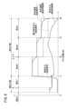
- FIG. 6 is a graph showing the change in molding conditions relative to the actual screw position and the change in actual molding results.
- FIG. 7 is a graph showing the change in molding conditions relative to the actual screw position and the change in actual molding results.
- FIG. 1 is a block diagram of a resin flow analysis result display system.
- FIG. 2 is a table showing an example of the time, screw position, injection speed, pressure and three-dimensional analysis data managed by the resin flow analysis device.
- FIG. 3 is a diagram showing an example of a three-dimensional display of the analysis
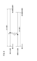
- FIG. 8 is an image diagram showing a state in which the stroke length of the screw in the actual molding differs from the stroke length of the screw in the analysis.
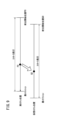
- FIG. 9 is an image diagram showing a state in which the injection start position in the actual molding differs from the injection start position in the analysis.
- FIG. 10 is a diagram showing an example of a graph display at a certain point in time during the virtual molding time.
- FIG. 11 is a diagram showing an example of a table display at a certain point in time during the virtual molding time.
- the resin flow analysis device analyzes the flow state of resin in an injection molding machine and calculates the molding conditions to be set in the injection molding machine.
- the resin flow analysis device cannot completely reproduce the flow state of resin in actual molding through analysis. Therefore, even if the molding conditions calculated by the resin flow analysis device are set in the injection molding machine, it is basically not possible to obtain a good molded product in the actual molding. Therefore, the user needs to adjust the molding conditions calculated by the resin flow analysis device.
- the molding conditions are adjusted based on the molded product obtained in the actual molding, the actual molding results, etc., and the analysis results obtained by the resin flow analysis device.
- the analysis results obtained by the resin flow analysis device are displayed on the display unit.
- the analysis results are associated with each time point or each screw position in the analysis.
- the user can display the analysis results corresponding to any time point or screw position on the display unit by operating a slide bar or the like to specify the time point or screw position in the analysis.
- the objective of this disclosure is to allow the user to easily perform operations to display analysis results corresponding to each molding condition on the display unit.
- First Embodiment is a block diagram of a resin flow analysis result display system 10.
- the resin flow analysis result display system 10 has an input unit 12, a display control unit 14, and a display unit 16.
- the resin flow analysis result display system 10 is connected to a resin flow analysis device 18 and an injection molding machine 20 via a network.
- the following information is managed in chronological order as the analysis results.
- the information is time, screw position, injection speed, pressure, and three-dimensional analysis data.
- Figure 2 is a table showing examples of time, screw position, injection speed, pressure, and three-dimensional analysis data managed by the resin flow analysis device 18.
- the resin flow analysis device 18 places multiple points in a virtual three-dimensional space. Each point has three-dimensional coordinate values.
- the resin flow analysis device 18 calculates the state of the resin at each point at predetermined time intervals during the analytical molding time.
- the state of the resin refers to the pressure, speed, temperature, and density of the resin.
- the state of the resin at each point, together with the three-dimensional coordinate values of each point, is managed as three-dimensional analysis data shown in Figure 2.
- the aforementioned molding time is the elapsed time based on the point in time when the screw starts to move in the injection process after the metering process is completed.
- the aforementioned analytical molding time is the molding time calculated by the resin flow analysis device 18.
- the analytical molding time may be referred to as the virtual molding time.
- the virtual molding time corresponds to the time shown in Figure 2.
- the display control unit 14 of the resin flow analysis result display system 10 acquires the analysis results from the resin flow analysis device 18.
- the display control unit 14 causes the display unit 16 to display a three-dimensional display 22 of the analysis results based on the three-dimensional analysis data at each point in time during the virtual molding time.
- Figure 3 is a diagram showing an example of the three-dimensional display 22 at a certain point in time during the virtual molding time.
- the display control unit 14 generates a three-dimensional display 22 by displaying, as polygons, each point on the boundary between the resin and substances other than resin at each point in the virtual molding time.
- Substances other than resin include the mold, air, etc.
- the flow path within the mold is drawn in a wireframe.
- the inflow range of the resin is displayed by polygons within the flow path.
- the temperature distribution of the resin is shown by shades of color on the polygons indicating the inflow range of the resin.
- the temperature distribution of the resin may be shown by a color scheme instead of shades of color.
- instead of displaying the temperature distribution, pressure distribution, density distribution, etc. may be displayed.
- the screw position changes depending on each point in the virtual molding time. Therefore, it can be said that the three-dimensional analysis data corresponds to the screw position.
- the screw position shown in Figure 2 is the analytical screw position.
- the analytical screw position is the screw position obtained as the analysis result in the resin flow analysis device 18.
- the analytical screw position may be referred to as the virtual screw position.
- the resin flow analysis device 18 calculates the molding conditions to be set in the injection molding machine 20.
- the injection molding machine 20 performs actual molding based on the molding conditions calculated by the resin flow analysis device 18.
- This actual molding produces a molded product and an actual molding result.
- the actual molding result is the detection value detected by various sensors provided in the injection molding machine 20 during actual molding.
- the actual molding result is the screw position, injection pressure, injection speed, etc. at each point in time during the molding time in actual molding.
- the molding time in actual molding is the actual elapsed time based on the point in time when the screw starts to move during the injection process of actual molding. Below, the molding time in actual molding may be referred to as the actual molding time.
- the screw position obtained as the actual molding result may be referred to as the actual screw position.
- the display control unit 14 controls the display unit 16 to display the molding conditions set in the injection molding machine 20 and a three-dimensional display 22 of the analysis results on the display unit 16.
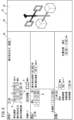
- Figures 4 and 5 are diagrams showing examples of the display on the display unit 16.
- the display unit 16 has a first display area 24 and a second display area 26.
- the molding conditions set in the injection molding machine 20 are displayed in the first display area 24.
- the three-dimensional display 22 is displayed in the second display area 26.
- the first display area 24 displays multiple molding conditions.
- the user can select one molding condition by operating the input unit 12.
- the second display area 26 displays a three-dimensional representation 22 of the analysis results corresponding to the selected molding condition.
- the item indicated by "A” in FIG. 4 indicates the injection switching position, which is the screw position at which the second stage injection speed and the third stage injection speed are switched.
- the injection switching position which is the screw position at which the second stage injection speed and the third stage injection speed are switched.
- the three-dimensional display 22 corresponding to the molding condition "10.00 mm" of the injection switching position is displayed in the second display area 26.
- the item indicated by "E” in FIG. 5 indicates the injection/hold pressure switching pressure, which is the injection pressure at which the injection process is switched to the holding pressure process.
- the injection/hold pressure switching pressure which is the injection pressure at which the injection process is switched to the holding pressure process.
- a three-dimensional display 22 corresponding to the molding condition of the injection/hold pressure switching pressure of "1.2 MPa" is displayed in the second display area 26.
- the user can select the above-mentioned injection switch position and injection hold pressure switch pressure, as well as the injection hold pressure switch position, maximum injection time, hold pressure, hold pressure time, maximum injection pressure, injection speed, etc.
- the injection/holding pressure switch position is the screw position at which the injection process switches to the holding pressure process.
- the maximum injection time is the maximum time for the injection process. When the elapsed time from the start of the injection process reaches the maximum injection time, the process moves to the holding pressure process.
- the holding pressure is the injection pressure held in the holding pressure process.
- the holding pressure time is the time for which the holding pressure is maintained in the holding pressure process.
- the maximum injection pressure is the maximum value of the injection pressure in the injection process. The screw is moved so as not to exceed this maximum injection pressure.
- the injection speed is the movement speed of the screw in the injection process.
- the display control unit 14 includes a calculation unit 28 and a storage unit 30 .
- the calculation unit 28 is a processor such as a CPU (Central Processing Unit) or a GPU (Graphics Processing Unit).
- the calculation unit 28 has a molding condition acquisition unit 32, a molding condition display control unit 34, a molding condition selection unit 36, an analysis result acquisition unit 38, an actual molding result acquisition unit 40, an analysis result selection unit 42, and an analysis result display control unit 44.
- the molding condition acquisition unit 32, the molding condition display control unit 34, the molding condition selection unit 36, the analysis result acquisition unit 38, the actual molding result acquisition unit 40, the analysis result selection unit 42, and the analysis result display control unit 44 are realized by the calculation unit 28 executing a program stored in the memory unit 30.
- At least a portion of the molding condition acquisition unit 32, molding condition display control unit 34, molding condition selection unit 36, analysis result acquisition unit 38, actual molding result acquisition unit 40, analysis result selection unit 42, and analysis result display control unit 44 may be realized by an integrated circuit such as an ASIC (Application Specific Integrated Circuit) or an FPGA (Field-Programmable Gate Array). At least a portion of the molding condition acquisition unit 32, molding condition display control unit 34, molding condition selection unit 36, analysis result acquisition unit 38, actual molding result acquisition unit 40, analysis result selection unit 42, and analysis result display control unit 44 may be realized by an electronic circuit including a discrete device.
- ASIC Application Specific Integrated Circuit
- FPGA Field-Programmable Gate Array
- the storage unit 30 is composed of a volatile memory (not shown) and a non-volatile memory (not shown).
- the volatile memory and the non-volatile memory are computer-readable storage media.
- the volatile memory is, for example, a random access memory (RAM).
- the non-volatile memory is, for example, a read only memory (ROM) or a flash memory. Data, etc. are stored, for example, in the volatile memory. Programs, tables, maps, etc. are stored, for example, in the non-volatile memory. At least a part of the storage unit 30 may be provided in the above-mentioned processor, integrated circuit, etc.
- the molding condition acquisition unit 32 acquires the molding conditions for each item set in the injection molding machine 20 from the injection molding machine 20.
- the molding condition display control unit 34 controls the display unit 16 to display the acquired molding conditions for each item in the first display area 24, as shown in FIG. 4 or FIG. 5.
- the molding condition selection unit 36 selects one of the multiple molding conditions set in the injection molding machine 20 based on the user's operation of the input unit 12.
- the input unit 12 is, for example, a touch panel provided on the screen of the display unit 16. In this case, the molding condition selection unit 36 selects the molding condition of the item displayed at the position on the screen of the display unit 16 where the user double-tapped.
- the analysis result acquisition unit 38 acquires the analysis results shown in FIG. 2 from the resin flow analysis device 18.
- the actual molding result acquisition unit 40 acquires the actual molding results from the injection molding machine 20.
- the actual molding results are the screw position (actual screw position), injection pressure, injection speed, etc. at each point in time during the actual molding time.
- the analysis result selection unit 42 selects one analysis result based on the molding conditions of the item selected by the user.
- the analysis result selection process performed by the analysis result selection unit 42 will be described in detail later.
- the analysis result display control unit 44 controls the display unit 16 to display a three-dimensional representation 22 of the selected analysis result in the second display area 26, as shown in FIG. 4 or FIG. 5.
- the analysis result display control unit 44 corresponds to the display control unit of the present invention.
- the resin flow analysis result display system 10 may be entirely mounted on the injection molding machine 20.
- the resin flow analysis result display system 10 may be configured with multiple devices each connected via a network.
- the input unit 12, the display control unit 14, and the display unit 16 may each be provided in separate devices.
- the memory unit 30 of the display control unit 14 may be installed in a device connected to the display control unit 14 via a network.
- molding condition acquisition unit 32, molding condition display control unit 34, molding condition selection unit 36, analysis result acquisition unit 38, actual molding result acquisition unit 40, and analysis result selection unit 42 may each be realized by a calculation unit provided in a separate device.
- the analysis result selection unit 42 determines the screw position in actual molding (actual screw position) from the molding conditions of the items selected by the user. In the subsequent second process, the analysis result selection unit 42 determines the analytical screw position (virtual screw position) that corresponds to the actual screw position. After completing the first and second processes, the analysis result selection unit 42 selects the analysis result that corresponds to the determined virtual screw position according to the table shown in FIG. 2.
- (Regarding the first process) 6 is a graph showing the change in molding conditions relative to the actual screw position and the change in actual molding results.
- the molding conditions shown in FIG. 6 show the molding conditions for each item shown in the first display area 24 in FIG.
- the injection speed is set at three stages during the injection process.
- the holding pressure is set at two stages during the holding pressure process.
- the switch from the injection process to the holding pressure process is determined by the screw position.
- the item indicated by "A” in Figure 4 indicates the injection switching position, which is the screw position at which the second stage injection speed and the third stage injection speed are switched.
- the actual screw position (10 mm) indicated by "A” in Figure 6 is obtained in the analysis result selection section 42.
- the item indicated by "B” in Figure 4 indicates the dwell time, which is the time for which the second stage holding pressure is maintained.
- the analysis result selection unit 42 determines the actual screw position indicated by "B” in Figure 6. This actual screw position is the position 0.2 seconds after the actual screw position reaches 5 mm and the dwell time has elapsed.
- the item indicated by "C” in Figure 4 indicates the maximum injection pressure when the screw is advanced at the third stage injection speed.
- the analysis result selection unit 42 determines the actual screw position (10 mm) indicated by "C" in Figure 6.
- the item indicated by "D” in Figure 4 indicates the injection speed for the third stage.
- the analysis result selection unit 42 determines the actual screw position (10 mm) indicated by "D" in Figure 6.
- FIG. 7 is a graph showing the change in molding conditions relative to the actual screw position and the change in the actual molding results.
- the molding conditions shown in FIG. 7 indicate the molding conditions for each item shown in the first display area 24 in FIG. 5.
- the injection speed is set at three stages during the injection process.
- the holding pressure is set at two stages during the holding pressure process.
- the switch from the injection process to the holding pressure process is determined by the injection pressure.
- the item indicated by "E” in Figure 5 indicates the injection/hold pressure switching pressure, which is the injection pressure at which the injection process switches to the holding pressure process.
- the analysis result selection unit 42 determines the actual screw position indicated by "E” in Figure 6. This actual screw position is the position at the point in time when the injection pressure reaches the injection/hold pressure switching pressure of 1.2 MPa.
- the above describes the processing of the analysis result selection unit 42 that determines the actual screw position from the molding conditions of the items selected by the user, but the processing of determining the actual molding time from the molding conditions of the items selected by the user is also performed in a similar manner.
- the analysis result selection unit 42 obtains a virtual screw position corresponding to the actual screw position.
- Two methods for obtaining a virtual screw position corresponding to the actual screw position will be described below.
- the first method is used when the stroke length of the screw in the actual molding is different from the stroke length of the screw in the analysis.
- the second method is used when the stroke lengths are the same but the injection start position in the actual molding is different from the injection start position in the analysis.
- the stroke length refers to the length from the injection start position of the screw to the minimum cushion.
- Figure 8 is an image diagram showing a state when the stroke length S1 of the screw in the actual molding differs from the stroke length T1 of the screw in the analysis.
- the virtual screw position Q1 corresponding to the actual screw position P1 can be calculated using the following formula.
- Figure 9 is an image showing a state where the stroke lengths are the same but the injection start position P0 in the actual molding is different from the injection start position Q0 in the analysis.
- the virtual screw position Q2 corresponding to the actual screw position P2 can be calculated using the following formula.
- the above describes the processing of the analysis result selection unit 42 that determines the virtual screw position from the actual screw position, but the processing of determining the virtual molding time from the actual molding time is also performed in a similar manner.
- the analysis result acquisition unit 38 acquires the analysis result associated with the virtual molding time or the virtual screw position.
- the molding condition selection unit 36 acquires the molding condition of one item selected by the user.
- the analysis result selection unit 42 selects the analysis result based on the molding condition of the selected item.
- the analysis result display control unit 44 causes the display unit 16 to display a three-dimensional display 22 of the selected analysis result. Thereby, the three-dimensional display 22 of the analysis result according to the molding condition of the selected item is displayed on the display unit 16 simply by the user performing an operation to select an item of the molding condition.
- the resin flow analysis result display system 10 can reduce the burden of the user's work of adjusting the molding conditions.
- the analysis result selection unit 42 determines the actual screw position according to the molding conditions of the selected item.
- the analysis result selection unit 42 calculates the virtual screw position corresponding to the determined actual screw position.
- the analysis result selection unit 42 selects the analysis result corresponding to the calculated virtual screw position. This allows the resin flow analysis result display system 10 to display on the display unit 16 a three-dimensional representation 22 of the analysis result according to the molding conditions of the selected item even if the actual screw position and the virtual screw position do not match.
- the user selects one item of molding conditions by operating the input unit 12.
- the user may be allowed to select two or more items of molding conditions.
- a three-dimensional representation 22 of a plurality of analysis results is displayed in the second display area 26 of the display unit 16.
- the display control unit 14 displays a three-dimensional display 22 of the analysis results in the second display area 26 of the display unit 16.
- the display form of the analysis results displayed in the second display area 26 of the display unit 16 may be another form.
- the display control unit 14 may display a graph display 50 of the analysis results on the display unit 16 based on the injection speed, screw position, and injection pressure at each point in time during the virtual molding time shown in FIG. 2.
- FIG. 10 is a diagram showing an example of the graph display 50 at a certain point in time during the virtual molding time.
- the graph display 50 shows the change in injection speed relative to the screw position, and the change in injection pressure relative to the screw position.
- the graph display 50 displays a position display 52 that shows the screw position corresponding to a certain point in the virtual molding time.
- the display control unit 14 may cause the display unit 16 to display a table display 54 of the analysis results based on the injection speed, screw position, injection pressure, and three-dimensional analysis data at each point in time during the virtual molding time shown in FIG. 2.
- FIG. 11 is a diagram showing an example of the display of the table display 54 at a certain point in time during the virtual molding time.
- the table display 54 displays the injection speed, screw position, injection pressure, and three-dimensional analysis data at each point in time in table format.
- the frame of the column corresponding to a certain point in time during the virtual molding time is indicated by a thick line.
- a resin flow analysis result display system (10) having a display unit (16) that displays analysis results (22, 50, 54) obtained in a resin flow analysis, the resin flow analysis result display system having an analysis result acquisition unit (38) that acquires the analysis results associated with each time point or each screw position in the resin flow analysis, a molding condition selection unit (36) that selects at least one molding condition from among a plurality of molding conditions set for an injection molding machine, an analysis result selection unit (42) that selects the analysis result in accordance with the molding condition of the selected item, and a display control unit (44) that causes the selected analysis result to be displayed on the display unit.
- the molding conditions may include at least one item of an injection switching position, which is a screw position at which the injection speed is switched in the injection process, and an injection/holding pressure switching position, which is a screw position at which the injection process is switched to a holding pressure process.
- the molding conditions may include at least one item of a maximum injection time, which is the maximum time of the injection process, and a dwell time for maintaining the holding pressure in the dwell process.
- the molding conditions may include at least one item of a maximum injection pressure, which is the maximum value of the injection pressure in the injection process, a holding pressure in the holding pressure process, and an injection/holding pressure switching pressure, which is the injection pressure at which the injection process is switched to the holding pressure process.
- the molding conditions may include at least an injection speed, which is a moving speed of a screw in an injection process.
- each of the analysis results is associated with each screw position in the resin flow analysis, and the analysis result selection unit may determine a screw position in actual molding according to the molding conditions of the selected item, calculate a screw position in the resin flow analysis that corresponds to the determined screw position in the actual molding, and select the analysis result that corresponds to the calculated screw position in the resin flow analysis.
- the display unit may display the molding conditions for each item, the display unit may have a touch panel, and the molding condition selection unit may select the molding conditions for the item displayed at the position on the screen of the display unit touched by the user.
- the display unit displays the molding conditions for each item, the display unit has a touch panel, and the molding condition selection unit may select the molding conditions for the item displayed at the position on the screen of the display unit where the user double-taps.
- the resin flow analysis result display system according to any one of Supplementary Notes 1 to 8 above may be configured by a plurality of devices each connected via a network.
- a resin flow analysis result display control method for displaying analysis results obtained in a resin flow analysis on a display unit the resin flow analysis result display control method acquiring the analysis results associated with each time point or each screw position in the resin flow analysis, selecting at least one molding condition from among a plurality of molding conditions set for an injection molding machine, selecting the analysis result according to the molding condition of the selected item, and displaying the selected analysis result on the display unit.
- each of the analysis results is associated with each screw position in the resin flow analysis, and the screw position in actual molding is obtained according to the molding conditions of the selected item, a screw position in the resin flow analysis corresponding to the obtained screw position in the actual molding is calculated, and the analysis result corresponding to the calculated screw position in the resin flow analysis is selected.
- Resin flow analysis result display system 16 Display unit 22: Three-dimensional display (analysis result) 36: Molding condition selection unit 38: Analysis result acquisition unit 42: Analysis result selection unit 44: Analysis result display control unit (display control unit) 50...Graph display (analysis results) 54...Table display (analysis results)
Landscapes
- Engineering & Computer Science (AREA)
- Manufacturing & Machinery (AREA)
- Mechanical Engineering (AREA)
- Injection Moulding Of Plastics Or The Like (AREA)
Abstract
Description
[樹脂流動解析結果表示システムの概要]
図1は、樹脂流動解析結果表示システム10のブロック図である。樹脂流動解析結果表示システム10は、入力部12、表示制御部14及び表示部16を有する。樹脂流動解析結果表示システム10は、樹脂流動解析装置18及び射出成形機20とネットワークにより接続される。
図1に示すように、表示制御部14は、演算部28及び記憶部30を有する。
解析結果選択部42において行われる解析結果の選択処理について説明する。解析結果の選択処理は、大きく2つの処理に分けられる。
図6は、実スクリュ位置に対する成形条件の変化、及び、実成形結果の変化を示すグラフである。図6に示す成形条件は、図4の第1表示領域24に示す各項目の成形条件を示す。
第2の処理では、解析結果選択部42は、実スクリュ位置に対応する仮想スクリュ位置を求める。実スクリュ位置に対応する仮想スクリュ位置を求める方法として、以下に2つの方法を説明する。1つ目の方法は、実成形におけるスクリュのストローク長と、解析におけるスクリュのストローク長とが異なる場合に用いられる。2つ目の方法は、ストローク長は等しいものの、実成形における射出開始位置と、解析における射出開始位置とが異なる場合に用いられる。なお、ストローク長とは、スクリュの射出開始位置から最小クッションまでの長さを示す。
本実施形態の樹脂流動解析結果表示システム10では、解析結果取得部38が、仮想成形時間又は仮想スクリュ位置に対応付けられた解析結果を取得する。成形条件選択部36が、ユーザにより選択された1つの項目の成形条件を取得する。解析結果選択部42は、選択された項目の成形条件に基づいて、解析結果を選択する。解析結果表示制御部44は、選択された解析結果の三次元表示22を表示部16に表示させる。これにより、ユーザが成形条件の項目を選択する操作を行うだけで、表示部16に選択された項目の成形条件に応じた解析結果の三次元表示22が表示される。その結果、樹脂流動解析結果表示システム10は、ユーザによる成形条件の調整作業の負担を軽減できる。
第1実施形態の樹脂流動解析結果表示システム10では、ユーザは、入力部12を操作することにより、1つの項目の成形条件を選択する。これに対して、ユーザが2以上の項目の成形条件を選択できるようにしてもよい。この場合、表示部16の第2表示領域26には、複数の解析結果の三次元表示22が表示される。
樹脂流動解析において取得された解析結果(22、50、54)を表示する表示部(16)を有する樹脂流動解析結果表示システム(10)であって、当該樹脂流動解析結果表示システムは、前記樹脂流動解析における各時点又は各スクリュ位置に対応付けられた前記解析結果を取得する解析結果取得部(38)と、射出成形機に対して設定された複数項目の成形条件のうち、少なくとも1つの項目の前記成形条件を選択する成形条件選択部(36)と、選択された項目の前記成形条件に応じて、前記解析結果を選択する解析結果選択部(42)と、選択された前記解析結果を前記表示部に表示させる表示制御部(44)と、を有する。
上記付記1に記載の樹脂流動解析結果表示システムにおいて、前記成形条件には、射出工程において射出速度を切り換えるスクリュ位置である射出切換位置、及び、射出工程から保圧工程に切り換えるスクリュ位置である射出保圧切換位置の少なくとも1つの項目が含まれてもよい。
上記付記1又は2に記載の樹脂流動解析結果表示システムにおいて、前記成形条件には、射出工程の最大時間である最大射出時間、及び、保圧工程における保持圧力を維持する保圧時間の少なくとも1つの項目が含まれてもよい。
上記付記1~3のいずれか1つに記載の樹脂流動解析結果表示システムにおいて、前記成形条件には、射出工程における射出圧力の最大値である最大射出圧力、保圧工程における保持圧力、及び、射出工程から保圧工程に切り換える射出圧力である射出保圧切換圧力の少なくとも1つの項目が含まれてもよい。
上記付記1~4のいずれか1つに記載の樹脂流動解析結果表示システムにおいて、前記成形条件には、射出工程におけるスクリュの移動速度である射出速度が少なくとも含まれてもよい。
上記付記1~5のいずれか1つに記載の樹脂流動解析結果表示システムにおいて、前記解析結果の各々は、前記樹脂流動解析における各スクリュ位置に対応付けられ、前記解析結果選択部は、選択された項目の前記成形条件に応じて、実成形におけるスクリュ位置を求め、求められた前記実成形におけるスクリュ位置に対応する、前記樹脂流動解析におけるスクリュ位置を算出し、算出された前記樹脂流動解析におけるスクリュ位置に対応する前記解析結果を選択してもよい。
上記付記1~6のいずれか1つに記載の樹脂流動解析結果表示システムにおいて、前記表示部は、各項目の前記成形条件を表示し、前記表示部は、タッチパネルを有し、前記成形条件選択部は、ユーザにより触れられた前記表示部の画面の位置に表示される項目の前記成形条件を選択してもよい。
上記付記1~6のいずれか1つに記載の樹脂流動解析結果表示システムにおいて、前記表示部は、各項目の前記成形条件を表示し、前記表示部は、タッチパネルを有し、前記成形条件選択部は、ユーザによりダブルタップ操作された前記表示部の画面の位置に表示される項目の前記成形条件を選択してもよい。
上記付記1~8のいずれか1つに記載の樹脂流動解析結果表示システムは、各々がネットワークにより接続された複数の機器により構成されてもよい。
樹脂流動解析において取得された解析結果を表示部に表示させる樹脂流動解析結果表示制御方法であって、当該樹脂流動解析結果表示制御方法は、前記樹脂流動解析における各時点又は各スクリュ位置に対応付けられた前記解析結果を取得し、射出成形機に対して設定された複数項目の成形条件のうち、少なくとも1つの項目の前記成形条件を選択し、選択された項目の前記成形条件に応じて、前記解析結果を選択し、選択された前記解析結果を前記表示部に表示させる。
上記付記10に記載の樹脂流動解析結果表示制御方法では、前記解析結果の各々は、前記樹脂流動解析における各スクリュ位置に対応付けられ、選択された項目の前記成形条件に応じて、実成形におけるスクリュ位置を求め、求められた前記実成形におけるスクリュ位置に対応する、前記樹脂流動解析におけるスクリュ位置を算出し、算出された前記樹脂流動解析におけるスクリュ位置に対応する前記解析結果を選択してもよい。
22…三次元表示(解析結果) 36…成形条件選択部
38…解析結果取得部
42…解析結果選択部
44…解析結果表示制御部(表示制御部)
50…グラフ表示(解析結果) 54…テーブル表示(解析結果)
Claims (11)
- 樹脂流動解析において取得された解析結果を表示する表示部を有する樹脂流動解析結果表示システムであって、
前記樹脂流動解析における各時点又は各スクリュ位置に対応付けられた前記解析結果を取得する解析結果取得部と、
射出成形機に対して設定された複数項目の成形条件のうち、少なくとも1つの項目の前記成形条件を選択する成形条件選択部と、
選択された項目の前記成形条件に応じて、前記解析結果を選択する解析結果選択部と、
選択された前記解析結果を前記表示部に表示させる表示制御部と、
を有する、樹脂流動解析結果表示システム。 - 請求項1に記載の樹脂流動解析結果表示システムにおいて、
前記成形条件には、射出工程において射出速度を切り換えるスクリュ位置である射出切換位置、及び、射出工程から保圧工程に切り換えるスクリュ位置である射出保圧切換位置の少なくとも1つの項目が含まれる、樹脂流動解析結果表示システム。 - 請求項1又は2に記載の樹脂流動解析結果表示システムにおいて、
前記成形条件には、射出工程の最大時間である最大射出時間、及び、保圧工程における保持圧力を維持する保圧時間の少なくとも1つの項目が含まれる、樹脂流動解析結果表示システム。 - 請求項1~3のいずれか1項に記載の樹脂流動解析結果表示システムにおいて、
前記成形条件には、射出工程における射出圧力の最大値である最大射出圧力、保圧工程における保持圧力、及び、射出工程から保圧工程に切り換える射出圧力である射出保圧切換圧力の少なくとも1つの項目が含まれる、樹脂流動解析結果表示システム。 - 請求項1~4のいずれか1項に記載の樹脂流動解析結果表示システムにおいて、
前記成形条件には、射出工程におけるスクリュの移動速度である射出速度が少なくとも含まれる、樹脂流動解析結果表示システム。 - 請求項1~5のいずれか1項に記載の樹脂流動解析結果表示システムにおいて、
前記解析結果の各々は、前記樹脂流動解析における各スクリュ位置に対応付けられ、
前記解析結果選択部は、
選択された項目の前記成形条件に応じて、実成形におけるスクリュ位置を求め、
求められた前記実成形におけるスクリュ位置に対応する、前記樹脂流動解析におけるスクリュ位置を算出し、
算出された前記樹脂流動解析におけるスクリュ位置に対応する前記解析結果を選択する、樹脂流動解析結果表示システム。 - 請求項1~6のいずれか1項に記載の樹脂流動解析結果表示システムにおいて、
前記表示部は、各項目の前記成形条件を表示し、
前記表示部は、タッチパネルを有し、
前記成形条件選択部は、ユーザにより触れられた前記表示部の画面の位置に表示される項目の前記成形条件を選択する、樹脂流動解析結果表示システム。 - 請求項1~6のいずれか1項に記載の樹脂流動解析結果表示システムにおいて、
前記表示部は、各項目の前記成形条件を表示し、
前記表示部は、タッチパネルを有し、
前記成形条件選択部は、ユーザによりダブルタップ操作された前記表示部の画面の位置に表示される項目の前記成形条件を選択する、樹脂流動解析結果表示システム。 - 請求項1~8のいずれか1項に記載の樹脂流動解析結果表示システムにおいて、
各々がネットワークにより接続された複数の機器により構成される、樹脂流動解析結果表示システム。 - 樹脂流動解析において取得された解析結果を表示部に表示させる樹脂流動解析結果表示制御方法であって、
前記樹脂流動解析における各時点又は各スクリュ位置に対応付けられた前記解析結果を取得し、
射出成形機に対して設定された複数項目の成形条件のうち、少なくとも1つの項目の前記成形条件を選択し、
選択された項目の前記成形条件に応じて、前記解析結果を選択し、
選択された前記解析結果を前記表示部に表示させる、樹脂流動解析結果表示制御方法。 - 請求項10に記載の樹脂流動解析結果表示制御方法において、
前記解析結果の各々は、前記樹脂流動解析における各スクリュ位置に対応付けられ、
選択された項目の前記成形条件に応じて、実成形におけるスクリュ位置を求め、
求められた前記実成形におけるスクリュ位置に対応する、前記樹脂流動解析におけるスクリュ位置を算出し、
算出された前記樹脂流動解析におけるスクリュ位置に対応する前記解析結果を選択する、樹脂流動解析結果表示制御方法。
Priority Applications (4)
| Application Number | Priority Date | Filing Date | Title |
|---|---|---|---|
| DE112022007672.0T DE112022007672T5 (de) | 2022-10-18 | 2022-10-18 | Anzeigesystem für Resinflussanalyseergebnisse und Steuerverfahren für die Resinflussanalyseergebnisanzeige |
| CN202280100859.2A CN120051364A (zh) | 2022-10-18 | 2022-10-18 | 树脂流动解析结果显示系统以及树脂流动解析结果显示控制方法 |
| PCT/JP2022/038754 WO2024084579A1 (ja) | 2022-10-18 | 2022-10-18 | 樹脂流動解析結果表示システム及び樹脂流動解析結果表示制御方法 |
| JP2024551092A JPWO2024084579A1 (ja) | 2022-10-18 | 2022-10-18 |
Applications Claiming Priority (1)
| Application Number | Priority Date | Filing Date | Title |
|---|---|---|---|
| PCT/JP2022/038754 WO2024084579A1 (ja) | 2022-10-18 | 2022-10-18 | 樹脂流動解析結果表示システム及び樹脂流動解析結果表示制御方法 |
Publications (1)
| Publication Number | Publication Date |
|---|---|
| WO2024084579A1 true WO2024084579A1 (ja) | 2024-04-25 |
Family
ID=90737153
Family Applications (1)
| Application Number | Title | Priority Date | Filing Date |
|---|---|---|---|
| PCT/JP2022/038754 Ceased WO2024084579A1 (ja) | 2022-10-18 | 2022-10-18 | 樹脂流動解析結果表示システム及び樹脂流動解析結果表示制御方法 |
Country Status (4)
| Country | Link |
|---|---|
| JP (1) | JPWO2024084579A1 (ja) |
| CN (1) | CN120051364A (ja) |
| DE (1) | DE112022007672T5 (ja) |
| WO (1) | WO2024084579A1 (ja) |
Citations (4)
| Publication number | Priority date | Publication date | Assignee | Title |
|---|---|---|---|---|
| JPH08174609A (ja) * | 1994-12-20 | 1996-07-09 | Ube Ind Ltd | 射出成形機の速度制御方法 |
| JP2001088187A (ja) * | 1999-09-21 | 2001-04-03 | Japan Steel Works Ltd:The | 射出成形機の適正成形条件導出システム及び方法 |
| JP2017113981A (ja) * | 2015-12-24 | 2017-06-29 | 東レエンジニアリング株式会社 | 成形品の設計支援方法、成形品の設計支援装置、コンピュータ・ソフトウェア、記憶媒体 |
| JP2020049703A (ja) * | 2018-09-25 | 2020-04-02 | 東芝機械株式会社 | 射出成形機、射出成形システムおよび射出制御方法 |
-
2022
- 2022-10-18 WO PCT/JP2022/038754 patent/WO2024084579A1/ja not_active Ceased
- 2022-10-18 JP JP2024551092A patent/JPWO2024084579A1/ja active Pending
- 2022-10-18 CN CN202280100859.2A patent/CN120051364A/zh active Pending
- 2022-10-18 DE DE112022007672.0T patent/DE112022007672T5/de active Pending
Patent Citations (4)
| Publication number | Priority date | Publication date | Assignee | Title |
|---|---|---|---|---|
| JPH08174609A (ja) * | 1994-12-20 | 1996-07-09 | Ube Ind Ltd | 射出成形機の速度制御方法 |
| JP2001088187A (ja) * | 1999-09-21 | 2001-04-03 | Japan Steel Works Ltd:The | 射出成形機の適正成形条件導出システム及び方法 |
| JP2017113981A (ja) * | 2015-12-24 | 2017-06-29 | 東レエンジニアリング株式会社 | 成形品の設計支援方法、成形品の設計支援装置、コンピュータ・ソフトウェア、記憶媒体 |
| JP2020049703A (ja) * | 2018-09-25 | 2020-04-02 | 東芝機械株式会社 | 射出成形機、射出成形システムおよび射出制御方法 |
Also Published As
| Publication number | Publication date |
|---|---|
| JPWO2024084579A1 (ja) | 2024-04-25 |
| CN120051364A (zh) | 2025-05-27 |
| DE112022007672T5 (de) | 2025-06-12 |
Similar Documents
| Publication | Publication Date | Title |
|---|---|---|
| JP4167282B2 (ja) | 射出成形機の支援装置 | |
| US10437229B2 (en) | Numerical controller | |
| EP1942403A2 (en) | Data scrolling apparatus and method for mobile terminal | |
| US20170146978A1 (en) | Control device for machine tool | |
| JP5421973B2 (ja) | 生産機械の表示装置 | |
| JP5733617B2 (ja) | 可読性評価方法、可読性評価装置及び可読性評価プログラム | |
| KR101674713B1 (ko) | 표시 장치, 제어 방법 및 기록 매체 | |
| JP3967655B2 (ja) | 射出成形機の表示装置及び射出成形機 | |
| WO2024084579A1 (ja) | 樹脂流動解析結果表示システム及び樹脂流動解析結果表示制御方法 | |
| KR937000279A (ko) | 금형 캐비티내의 수지위치를 모니터하는 방법 | |
| WO2024095323A1 (ja) | 成形条件入力システム及び成形条件入力システムの制御方法 | |
| JP2003181899A (ja) | 成形機 | |
| JP2015041216A5 (ja) | ||
| JP5485775B2 (ja) | タッチパネルにおける入力ウィンドウの表示方法及び装置 | |
| WO2024084593A1 (ja) | 樹脂流動解析結果表示装置、及び、樹脂流動解析結果表示装置の制御方法 | |
| JP4081242B2 (ja) | モニタリング表示装置および表示方法 | |
| WO2024127553A1 (ja) | 成形判定装置、射出成形機、及び、成形判定方法 | |
| JP2002307512A (ja) | 射出成形機における成形条件換算用プログラム及び射出成形機の制御装置 | |
| JP2007072915A5 (ja) | ||
| JP5632348B2 (ja) | 測定装置 | |
| JP6802229B2 (ja) | 射出成形機の表示装置及び表示システム | |
| JP7557078B2 (ja) | 産業機械、及び産業機械の制御方法 | |
| JP2006056261A (ja) | モニタリング表示装置および表示方法 | |
| JP2017024381A (ja) | 成形機 | |
| JP7801880B2 (ja) | グラフ生成装置及びグラフ生成方法 |
Legal Events
| Date | Code | Title | Description |
|---|---|---|---|
| 121 | Ep: the epo has been informed by wipo that ep was designated in this application |
Ref document number: 22962691 Country of ref document: EP Kind code of ref document: A1 |
|
| WWE | Wipo information: entry into national phase |
Ref document number: 2024551092 Country of ref document: JP |
|
| WWE | Wipo information: entry into national phase |
Ref document number: 202280100859.2 Country of ref document: CN |
|
| WWE | Wipo information: entry into national phase |
Ref document number: 112022007672 Country of ref document: DE |
|
| WWP | Wipo information: published in national office |
Ref document number: 202280100859.2 Country of ref document: CN |
|
| WWP | Wipo information: published in national office |
Ref document number: 112022007672 Country of ref document: DE |
|
| 122 | Ep: pct application non-entry in european phase |
Ref document number: 22962691 Country of ref document: EP Kind code of ref document: A1 |