WO2024084367A1 - 電池及び電池の作製方法 - Google Patents
電池及び電池の作製方法 Download PDFInfo
- Publication number
- WO2024084367A1 WO2024084367A1 PCT/IB2023/060396 IB2023060396W WO2024084367A1 WO 2024084367 A1 WO2024084367 A1 WO 2024084367A1 IB 2023060396 W IB2023060396 W IB 2023060396W WO 2024084367 A1 WO2024084367 A1 WO 2024084367A1
- Authority
- WO
- WIPO (PCT)
- Prior art keywords
- battery
- separator
- electrode
- secondary battery
- integrated
- Prior art date
- Legal status (The legal status is an assumption and is not a legal conclusion. Google has not performed a legal analysis and makes no representation as to the accuracy of the status listed.)
- Ceased
Links
Images


















Classifications
-
- H—ELECTRICITY
- H01—ELECTRIC ELEMENTS
- H01M—PROCESSES OR MEANS, e.g. BATTERIES, FOR THE DIRECT CONVERSION OF CHEMICAL ENERGY INTO ELECTRICAL ENERGY
- H01M10/00—Secondary cells; Manufacture thereof
- H01M10/05—Accumulators with non-aqueous electrolyte
- H01M10/058—Construction or manufacture
-
- H—ELECTRICITY
- H01—ELECTRIC ELEMENTS
- H01M—PROCESSES OR MEANS, e.g. BATTERIES, FOR THE DIRECT CONVERSION OF CHEMICAL ENERGY INTO ELECTRICAL ENERGY
- H01M10/00—Secondary cells; Manufacture thereof
- H01M10/05—Accumulators with non-aqueous electrolyte
- H01M10/052—Li-accumulators
- H01M10/0525—Rocking-chair batteries, i.e. batteries with lithium insertion or intercalation in both electrodes; Lithium-ion batteries
-
- H—ELECTRICITY
- H01—ELECTRIC ELEMENTS
- H01M—PROCESSES OR MEANS, e.g. BATTERIES, FOR THE DIRECT CONVERSION OF CHEMICAL ENERGY INTO ELECTRICAL ENERGY
- H01M4/00—Electrodes
- H01M4/02—Electrodes composed of, or comprising, active material
- H01M4/13—Electrodes for accumulators with non-aqueous electrolyte, e.g. for lithium-accumulators; Processes of manufacture thereof
- H01M4/133—Electrodes based on carbonaceous material, e.g. graphite-intercalation compounds or CFx
-
- H—ELECTRICITY
- H01—ELECTRIC ELEMENTS
- H01M—PROCESSES OR MEANS, e.g. BATTERIES, FOR THE DIRECT CONVERSION OF CHEMICAL ENERGY INTO ELECTRICAL ENERGY
- H01M4/00—Electrodes
- H01M4/02—Electrodes composed of, or comprising, active material
- H01M4/13—Electrodes for accumulators with non-aqueous electrolyte, e.g. for lithium-accumulators; Processes of manufacture thereof
- H01M4/134—Electrodes based on metals, Si or alloys
-
- H—ELECTRICITY
- H01—ELECTRIC ELEMENTS
- H01M—PROCESSES OR MEANS, e.g. BATTERIES, FOR THE DIRECT CONVERSION OF CHEMICAL ENERGY INTO ELECTRICAL ENERGY
- H01M4/00—Electrodes
- H01M4/02—Electrodes composed of, or comprising, active material
- H01M4/36—Selection of substances as active materials, active masses, active liquids
-
- H—ELECTRICITY
- H01—ELECTRIC ELEMENTS
- H01M—PROCESSES OR MEANS, e.g. BATTERIES, FOR THE DIRECT CONVERSION OF CHEMICAL ENERGY INTO ELECTRICAL ENERGY
- H01M4/00—Electrodes
- H01M4/02—Electrodes composed of, or comprising, active material
- H01M4/36—Selection of substances as active materials, active masses, active liquids
- H01M4/38—Selection of substances as active materials, active masses, active liquids of elements or alloys
-
- H—ELECTRICITY
- H01—ELECTRIC ELEMENTS
- H01M—PROCESSES OR MEANS, e.g. BATTERIES, FOR THE DIRECT CONVERSION OF CHEMICAL ENERGY INTO ELECTRICAL ENERGY
- H01M4/00—Electrodes
- H01M4/02—Electrodes composed of, or comprising, active material
- H01M4/36—Selection of substances as active materials, active masses, active liquids
- H01M4/58—Selection of substances as active materials, active masses, active liquids of inorganic compounds other than oxides or hydroxides, e.g. sulfides, selenides, tellurides, halogenides or LiCoFy; of polyanionic structures, e.g. phosphates, silicates or borates
- H01M4/583—Carbonaceous material, e.g. graphite-intercalation compounds or CFx
- H01M4/587—Carbonaceous material, e.g. graphite-intercalation compounds or CFx for inserting or intercalating light metals
-
- H—ELECTRICITY
- H01—ELECTRIC ELEMENTS
- H01M—PROCESSES OR MEANS, e.g. BATTERIES, FOR THE DIRECT CONVERSION OF CHEMICAL ENERGY INTO ELECTRICAL ENERGY
- H01M50/00—Constructional details or processes of manufacture of the non-active parts of electrochemical cells other than fuel cells, e.g. hybrid cells
- H01M50/40—Separators; Membranes; Diaphragms; Spacing elements inside cells
- H01M50/409—Separators, membranes or diaphragms characterised by the material
- H01M50/411—Organic material
- H01M50/414—Synthetic resins, e.g. thermoplastics or thermosetting resins
- H01M50/417—Polyolefins
-
- H—ELECTRICITY
- H01—ELECTRIC ELEMENTS
- H01M—PROCESSES OR MEANS, e.g. BATTERIES, FOR THE DIRECT CONVERSION OF CHEMICAL ENERGY INTO ELECTRICAL ENERGY
- H01M50/00—Constructional details or processes of manufacture of the non-active parts of electrochemical cells other than fuel cells, e.g. hybrid cells
- H01M50/40—Separators; Membranes; Diaphragms; Spacing elements inside cells
- H01M50/46—Separators, membranes or diaphragms characterised by their combination with electrodes
-
- Y—GENERAL TAGGING OF NEW TECHNOLOGICAL DEVELOPMENTS; GENERAL TAGGING OF CROSS-SECTIONAL TECHNOLOGIES SPANNING OVER SEVERAL SECTIONS OF THE IPC; TECHNICAL SUBJECTS COVERED BY FORMER USPC CROSS-REFERENCE ART COLLECTIONS [XRACs] AND DIGESTS
- Y02—TECHNOLOGIES OR APPLICATIONS FOR MITIGATION OR ADAPTATION AGAINST CLIMATE CHANGE
- Y02E—REDUCTION OF GREENHOUSE GAS [GHG] EMISSIONS, RELATED TO ENERGY GENERATION, TRANSMISSION OR DISTRIBUTION
- Y02E60/00—Enabling technologies; Technologies with a potential or indirect contribution to GHG emissions mitigation
- Y02E60/10—Energy storage using batteries
Definitions
- One aspect of the present invention relates to a power storage device (also called a battery or secondary battery).
- the present invention is not limited to the above fields, and relates to a semiconductor device, a display device, a light-emitting device, a lighting device, an electronic device, a vehicle, and a manufacturing method thereof.
- the above-mentioned semiconductor device, display device, light-emitting device, lighting device, electronic device, and vehicle can use the battery of the present invention as a necessary power source.
- the battery include secondary batteries such as lithium ion batteries and sodium ion batteries.
- the above-mentioned electronic devices include information terminal devices equipped with lithium ion batteries.
- the above-mentioned power storage devices include stationary power storage devices.
- lithium-ion batteries lithium-ion batteries
- lithium-ion capacitors air batteries
- all-solid-state batteries all-solid-state batteries.
- lithium-ion batteries are used in a variety of fields and applications.
- characteristics required of lithium-ion batteries are high energy density per unit weight, high energy density per unit volume, excellent cycle characteristics, and safety in a variety of operating environments, and development is being actively conducted from various perspectives.
- Patent Document 1 examines the electrode structure of lithium-ion batteries.
- Lithium-ion batteries are required to be lightweight and small. However, at the same time, they are required to have a high discharge capacity. For this reason, efforts are being made to reduce the weight and size of lithium-ion batteries by thinning the current collectors (metal foils with a thickness of about 10 ⁇ m are used), separators, and exterior bodies, which do not contribute to the discharge capacity among the components that make up the lithium-ion battery.
- Patent Document 1 discloses a battery structure that does not have a metal foil as a current collector, and a method for manufacturing the same. However, there is room for improvement in the battery structure and manufacturing method.
- an objective is to provide a battery structure that does not have copper foil as a current collector.
- an objective is to provide a method for manufacturing a battery that does not have copper foil as a current collector.
- an objective is to prevent the elution of copper ions into the electrolyte in an overdischarge state by providing a battery that does not have copper foil as a current collector.
- one aspect of the present invention has the objective of providing a novel electrode, battery, or a method for manufacturing the same.
- One aspect of the present invention is a battery having a separator-integrated electrode, the separator-integrated electrode having a separator, a carbon particle layer, and a silicon layer located between the separator and the carbon particle layer.
- One aspect of the present invention is a battery having a separator-integrated electrode and an exterior body, the separator-integrated electrode having a separator, a carbon particle layer, and a silicon layer located between the separator and the carbon particle layer, and the carbon particle layer and the exterior body having an area where they are in contact.
- the thickness of the silicon layer is 100 nm or more and 200 nm or less.
- the separator contains polypropylene.
- one aspect of the present invention is a method for producing a battery equipped with a separator-integrated electrode having a separator, a carbon particle layer, and a silicon layer located between the separator and the carbon particle layer, the method comprising a first step of producing a silicon layer on the separator using a sputtering method, and a second step of producing a carbon particle layer by applying a slurry containing carbon particles onto the silicon layer, the thickness of the silicon layer being 100 nm or more and 200 nm or less.
- the slurry contains N-methyl-pyrrolidone.
- the separator contains polypropylene.
- a lightweight battery can be provided.
- a method for manufacturing a lightweight battery can be provided.
- a lightweight electrode can be provided.
- a method for manufacturing a lightweight electrode can be provided.
- a small battery can be provided.
- a method for manufacturing a small battery can be provided.
- a small electrode can be provided.
- a method for manufacturing a small electrode can be provided.
- one aspect of the present invention can provide a battery structure that does not have metal foil as a current collector in at least one of the positive electrode or negative electrode.
- a method for manufacturing a battery that does not have metal foil as a current collector in at least one of the positive electrode or negative electrode can be provided.
- one embodiment of the present invention can provide a battery structure that does not have copper foil as a current collector.
- a method for manufacturing a battery that does not have copper foil as a current collector can be provided.
- by making a battery that does not have copper foil as a current collector it is possible to prevent the elution of copper ions into the electrolyte in an overdischarge state.
- one aspect of the present invention can provide a novel electrode, battery, or method for manufacturing the same.
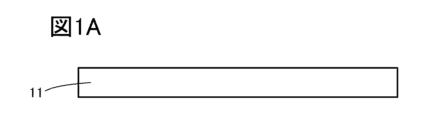
- FIGS. 1A to 1D are diagrams illustrating a method for producing a separator-integrated electrode and its structure.
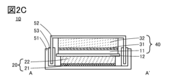
- 2A to 2C are diagrams illustrating the structure of a battery having separator-integrated electrodes.
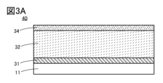
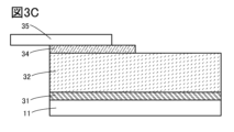
- 3A to 3C are diagrams illustrating modified examples of the separator-integrated electrode structure.
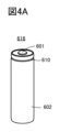
- Fig. 4A shows an example of a cylindrical secondary battery
- Fig. 4B shows an example of a cylindrical secondary battery
- Fig. 4C shows an example of a plurality of cylindrical secondary batteries
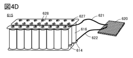
- Fig. 4D shows an example of a power storage system having a plurality of cylindrical secondary batteries.
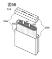
- 5A and 5B are diagrams for explaining an example of a secondary battery
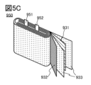
- FIG. 5C is a diagram showing the inside of the secondary battery.
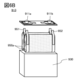
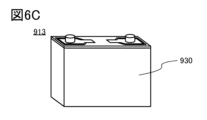
- FIGS. 6A to 6C are diagrams illustrating an example of a secondary battery.
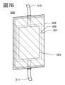
- 7A and 7B are diagrams showing the external appearance of a secondary battery.
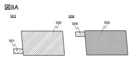
- 8A to 8C are diagrams illustrating a method for manufacturing a secondary battery.
- FIG. 9A shows an example of the configuration of a battery pack
- FIG. 9B shows an example of the configuration of a battery pack
- FIG. 9C shows an example of the configuration of a battery pack.
- FIG. 10A is a perspective view of a battery pack showing one embodiment of the present invention
- FIG. 10B is a block diagram of the battery pack
- FIG. 10C is a block diagram of a vehicle having the battery pack.
- 11A to 11D are diagrams illustrating an example of a transportation vehicle, and Fig.
- FIG. 11E is a diagram illustrating an example of an artificial satellite.
- 12A and 12B are diagrams illustrating a power storage device of one embodiment of the present invention.
- FIG. 13A is a diagram showing an electric bicycle
- FIG. 13B is a diagram showing a secondary battery of the electric bicycle
- FIG. 13C is a diagram explaining a scooter.
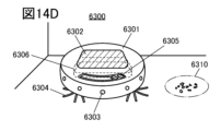
- 14A to 14D are diagrams illustrating an example of an electronic device.
- FIG. 15A shows an example of a wearable device
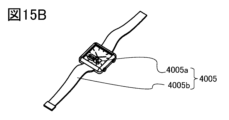
- FIG. 15B shows a perspective view of a wristwatch type device
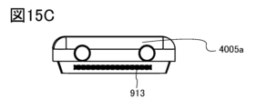
- FIG. 15C is a diagram illustrating a side view of the wristwatch type device.
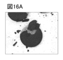
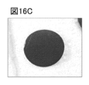
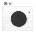
- 16A to 16D are SEM images described in Example 1.
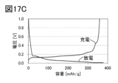
- 17A to 17C are graphs of the charge/discharge characteristics described in Example 1.
- particles does not necessarily refer to spherical shapes (cross-sectional shape being circular), but may refer to shapes such as ellipses, rectangles, trapezoids, triangles, squares with rounded corners, asymmetric shapes, and the like in cross-sectional shape of individual particles, and furthermore, individual particles may be irregular in shape.
- One embodiment of the present invention has a structure in which a separator and an electrode are integrated. Such a structure may be called an electrode integrated with a separator. Note that in this embodiment, a structure of an electrode integrated with a separator and a manufacturing method thereof will be described. In this specification, an electrode integrated with a separator is called a separator-integrated electrode.
- Another aspect of the present invention is characterized by an electrode configuration that does not have a metal foil as a current collector.
- one aspect of the present invention is characterized by an electrode configuration that does not have copper foil as a current collector.
- the electrodes described in this embodiment can be used as the positive or negative electrodes of a battery.
- the electrode in a battery in which the electrode is used as one of the positive and negative electrodes, if the electrode has a higher reaction potential than the other electrode, the electrode is called a positive electrode.
- the electrode in a battery in which the electrode is used as one of the positive and negative electrodes, if the electrode has a lower reaction potential than the other electrode, the electrode is called a negative electrode.
- FIGS. 1A to 1C are cross-sectional views illustrating a method for producing a separator-integrated electrode.
- FIG. 1D is an enlarged view of area A indicated by a dashed line in FIG. 1C.
- the separator 11 can be made of, for example, cellulose-containing fibers such as paper, nonwoven fabric, glass fiber, ceramics, or a porous film made of nylon (polyamide), polyimide, vinylon (polyvinyl alcohol fiber), polyester, acrylic, polyolefin, or polyurethane.
- cellulose-containing fibers such as paper, nonwoven fabric, glass fiber, ceramics
- a porous film made of nylon (polyamide), polyimide, vinylon (polyvinyl alcohol fiber), polyester, acrylic, polyolefin, or polyurethane.
- a porous polypropylene film can be used as a porous film made of polyolefin.
- the separator may have a multi-layer structure.
- an organic material film such as polypropylene or polyethylene may be coated with a ceramic material, a fluorine material, a polyamide material, a polyimide material, or a mixture of these.
- ceramic materials that can be used include aluminum oxide particles (alumina, boehmite, etc.) and silicon oxide particles.
- fluorine materials that can be used include PVDF and polytetrafluoroethylene.
- polyamide materials that can be used include nylon and aramid (meta-aramid, para-aramid).
- Coating with ceramic materials improves oxidation resistance, suppressing the deterioration of the separator during high-voltage charging and improving battery reliability. Coating with fluorine-based materials also improves adhesion between the separator and electrodes, improving output characteristics. Coating with polyamide-based materials, especially aramid, improves heat resistance, improving battery safety.
- the electrode integrated with the separator is a negative electrode.
- the safety of the battery can be maintained even if the overall thickness of the separator is thin, allowing the capacity per unit volume of the battery to be increased.
- a silicon layer 31 is formed on the separator 11.
- the silicon layer 31 can be formed by sputtering.
- the silicon film may be formed by CVD, vacuum deposition, PLD, or the like.
- the thickness of the silicon layer 31 is preferably 50 nm to 1000 nm, and more preferably 100 nm to 200 nm. If the thickness of the silicon layer 31 is thinner than 50 nm, the solvent of the slurry may penetrate through the gaps (pinholes, etc.) of the silicon layer 31 during the preparation of the carbon particle layer 32 provided on the silicon layer 31, and as a result, the separator 11 may be dissolved by the solvent, and the silicon layer 31 may peel off.
- the thickness is thicker than 1000 nm, the resistance of the silicon layer 31 may increase, and the battery performance may decrease.
- the thickness of the separator 11 should be 5 ⁇ m or more, preferably 10 ⁇ m or more, to avoid significant deformation due to membrane stress caused by the silicon layer 31.
- a carbon particle layer 32 is formed on the silicon layer 31.
- the carbon particle layer 32 can be formed, for example, by applying a slurry containing graphite particles onto the silicon layer 31 using a blade coater or the like, and then drying the solvent contained in the slurry containing graphite particles using a drying oven or the like. Therefore, the carbon particle layer 32 is sometimes called a graphite layer, a graphite particle layer, or an applied electrode layer.
- a slot die coater, a lip coater, a reverse coater, a gravure coater, or the like can also be used as a method for applying the slurry.
- the thickness of the carbon particle layer 32 is preferably 5 ⁇ m or more and 200 ⁇ m or less, and more preferably 10 ⁇ m or more and 100 ⁇ m or less.
- separator-integrated electrode 40 can be produced in which the separator and electrode are integrated.
- the configuration of the separator-integrated electrode 40 is described in FIG. 1D.
- the separator-integrated electrode 40 has a separator 11, a silicon layer 31, and a carbon particle layer 32.
- the separator 11 has the function of separating the positive electrode and the negative electrode, and the function of allowing the electrolyte to pass through. Therefore, the separator 11 has many pores, as shown in Figure 1D.
- silicon layer 31 is formed on the upper surface of separator 11. Note that, as shown in silicon layer 31a in the figure, a part of silicon layer 31 may be formed inside a pore in separator 11. Silicon layer 31 may also have silicon oxide on the surface layer.
- the carbon particle layer 32 is formed so as to be in contact with the upper surface of the silicon layer 31.
- the carbon particle layer 32 has carbon particles 33 and a binder 13.
- the carbon particle layer 32 may also have a conductive material 14.
- graphite naturally graphite, artificial graphite
- easily graphitizable carbon soft carbon
- non-graphitizable carbon hard carbon
- Graphite includes artificial graphite and natural graphite.
- artificial graphite include mesocarbon microbeads (MCMB), coke-based artificial graphite, and pitch-based artificial graphite.
- MCMB mesocarbon microbeads
- pitch-based artificial graphite spherical graphite having a spherical shape
- MCMB may have a spherical shape, which is preferable.
- it is relatively easy to reduce the surface area of MCMB which may be preferable.
- natural graphite include flake graphite and spheroidized natural graphite.
- Non-graphitizable carbon can be obtained, for example, by firing synthetic resins such as phenolic resins, or organic matter derived from plants.
- the non-graphitizable carbon contained in the negative electrode active material of a lithium-ion battery according to one embodiment of the present invention preferably has a (002) plane spacing measured by X-ray diffraction (XRD) of 0.34 nm or more and 0.50 nm or less, and more preferably 0.35 nm or more and 0.42 nm or less.
- XRD X-ray diffraction
- the binder 13 it is preferable to use a rubber material such as styrene-butadiene rubber (SBR), styrene-isoprene-styrene rubber, acrylonitrile-butadiene rubber, butadiene rubber, or ethylene-propylene-diene copolymer.
- SBR styrene-butadiene rubber
- styrene-isoprene-styrene rubber acrylonitrile-butadiene rubber
- butadiene rubber butadiene rubber
- Fluoro rubber can also be used as the binder.
- a water-soluble polymer as the binder.
- polysaccharides can be used as the water-soluble polymer.
- cellulose derivatives such as carboxymethyl cellulose (CMC), methyl cellulose, ethyl cellulose, hydroxypropyl cellulose, diacetyl cellulose, and regenerated cellulose, or starch can be used as the polysaccharide.
- CMC carboxymethyl cellulose
- methyl cellulose methyl cellulose
- ethyl cellulose methyl cellulose
- hydroxypropyl cellulose diacetyl cellulose
- regenerated cellulose or starch
- polystyrene polymethyl acrylate, polymethyl methacrylate (polymethyl methacrylate, PMMA), sodium polyacrylate, polyvinyl alcohol (PVA), polyethylene oxide (PEO), polypropylene oxide, polyimide, polyvinyl chloride, polytetrafluoroethylene, polyethylene, polypropylene, polyisobutylene, polyethylene terephthalate, nylon, polyvinylidene fluoride (PVDF), polyacrylonitrile (PAN), ethylene propylene diene polymer, polyvinyl acetate, and nitrocellulose as the binder.
- PVDF polyvinylidene fluoride
- PAN polyacrylonitrile
- a material with particularly excellent viscosity adjustment effects may be used in combination with other materials.
- rubber materials have excellent adhesive strength and elasticity, it may be difficult to adjust the viscosity when mixed with a solvent. In such cases, it is preferable to mix with a material with particularly excellent viscosity adjustment effects.
- a water-soluble polymer may be used as a material with particularly excellent viscosity adjustment effects.
- the above-mentioned polysaccharides for example, carboxymethylcellulose (CMC), methylcellulose, ethylcellulose, hydroxypropylcellulose, and diacetylcellulose, cellulose derivatives such as regenerated cellulose, or starch may be used.
- CMC carboxymethylcellulose
- methylcellulose methylcellulose
- ethylcellulose methylcellulose
- hydroxypropylcellulose hydroxypropylcellulose
- diacetylcellulose cellulose derivatives such as regenerated cellulose, or starch
- the solubility of cellulose derivatives such as carboxymethylcellulose can be increased by converting them into salts such as sodium or ammonium salts of carboxymethylcellulose, making them more effective as viscosity adjusters. Increasing the solubility can also increase the dispersibility with the active material or other components when preparing an electrode slurry.
- the cellulose and cellulose derivatives used as electrode binders include their salts.
- Water-soluble polymers stabilize the viscosity by dissolving in water, and can stably disperse active materials and other materials combined as binders, such as styrene-butadiene rubber, in an aqueous solution.
- binders such as styrene-butadiene rubber
- cellulose derivatives such as carboxymethyl cellulose
- functional groups such as hydroxyl or carboxyl groups
- the polymers are expected to interact with each other and widely cover the surface of the active material.
- a passive film is a film that has no electrical conductivity or has extremely low electrical conductivity.
- a passive film when a passive film is formed on the surface of an active material, it can suppress decomposition of the electrolyte at the battery reaction potential. Furthermore, it is even more desirable for the passive film to suppress electrical conductivity while still being able to conduct lithium ions.
- the conductive material 14 may be, for example, one or more of the following: carbon black such as acetylene black and furnace black; graphite such as artificial graphite and natural graphite; carbon fibers such as carbon nanofibers and carbon nanotubes; and graphene compounds.
- carbon fiber for example, mesophase pitch-based carbon fiber, isotropic pitch-based carbon fiber, etc. can be used.
- carbon nanofiber or carbon nanotube can be used as the carbon fiber. Carbon nanotube can be produced, for example, by vapor phase growth method.
- the content of the conductive material relative to the total amount of the active material layer is preferably 0.5 wt% or more and 10 wt% or less, and more preferably 1 wt% or more and 5 wt% or less.
- graphene compounds Unlike granular conductive materials such as carbon black, which make point contact with the active material, graphene compounds enable surface contact with low contact resistance, so a smaller amount than normal conductive materials can improve the electrical conductivity between the granular active material and the graphene compound. This makes it possible to increase the ratio of active material in the active material layer, thereby increasing the discharge capacity of the battery.
- Particulate carbon-containing compounds such as carbon black and graphite, or fibrous carbon-containing compounds such as carbon nanotubes
- a tiny space refers to, for example, the area between multiple active materials.
- the separator 11 and carbon particle layer 32 of the separator-integrated electrode 40 are integrated via the silicon layer 31.
- the separator-integrated electrode 40 does not have a metal foil.
- the separator-integrated electrode 40 can be produced without using a metal foil.
- a battery using the separator-integrated electrode 40 can be made lighter.
- a battery using the separator-integrated electrode 40 can be made smaller.
- the separator-integrated electrode 40 is used as the negative electrode, since it does not have a metal foil, particularly a copper foil, copper ions do not leach from the copper foil into the electrolyte in an over-discharge state, making it a safe battery.
- FIGS. 2A to 2C are diagrams illustrating a coin-type battery, and illustrate an example in which a separator-integrated electrode 40 is used as the negative electrode.
- FIG. 2A is a perspective view of a coin battery.
- FIG. 2B is a cross-sectional view taken along dashed line A-A' in FIG. 2A.
- FIG. 2C is a modified example of FIG. 2B.
- the coin battery 10 has a positive electrode can 51, a negative electrode can 52, and a gasket 53, and the positive electrode can 51 and the negative electrode can 52 overlap with the gasket 53 interposed therebetween.
- the positive electrode can 51, the negative electrode can 52, and the gasket 53 may be referred to as an exterior body.
- the positive electrode 20 and the separator-integrated electrode 40 are located inside the exterior body. Although not shown, an electrolyte is present inside the exterior body.
- the positive electrode 20 has a positive electrode current collector 21 and a positive electrode active material layer 22 provided on the positive electrode current collector.
- the separator-integrated electrode 40 is as described above.
- the positive electrode 20 and the separator-integrated electrode 40 are stacked so that the positive electrode active material layer 22 and the separator 11 of the separator-integrated electrode 40 are in contact with each other.
- the separator-integrated electrode 40 of one embodiment of the present invention does not have a current collector. Therefore, the carbon particle layer 32 of the separator-integrated electrode 40 may have an area in contact with the negative electrode can 52, which is the exterior body.
- a separator 12 may be provided between the positive electrode 20 and the separator-integrated electrode 40. Also, as shown in FIG. 2C, the area of the separator-integrated electrode 40 may be made larger than the area of the positive electrode 20.
- the separator-integrated electrode 40 of one embodiment of the present invention can be an electrode with a structure that does not have a current collector. Therefore, a battery having a separator-integrated electrode 40 can realize a battery structure that does not have a current collector in at least one of the positive electrode or negative electrode. Therefore, a battery having a separator-integrated electrode 40 can realize a lightweight battery structure. Alternatively, a battery having a separator-integrated electrode 40 can realize a small battery structure.
- the separator-integrated electrode 40 is not limited to the configuration shown in Figs. 1 and 2, but may have a metal layer 34 on a carbon particle layer 32 as shown in Fig. 3A.
- the metal layer 34 may be provided so as to cover the entire surface of the carbon particle layer 32, or may be provided so as to cover a portion of the carbon particle layer 32 as shown in Fig. 3B.
- the metal layer 34 and the lead 35 may be connected as shown in FIG. 3C.
- the metal layer 34 is preferably produced by a gas phase method such as sputtering, vapor deposition, or CVD.
- a gas phase method such as sputtering, vapor deposition, or CVD.
- the metal layer 34 may be made of, for example, any one or more of Ti, Pb, Zn, Sn, Mg, Zr, In, Cu, Ni, and Li.
- the thickness of the metal layer 34 may be 10 nm or more and 20 ⁇ m or less, preferably 10 nm or more and 10 ⁇ m or less, and more preferably 10 nm or more and 5 ⁇ m or less.
- the separator-integrated electrode 40 can be an electrode having a structure that does not have a metal foil as a current collector, even when it has a metal layer 34. Therefore, a battery having a separator-integrated electrode 40 can realize a battery structure that does not have a metal foil as a current collector in at least one of the positive electrode or negative electrode. Therefore, a battery having a separator-integrated electrode 40 can realize a lightweight battery structure. Or, a battery having a separator-integrated electrode 40 can realize a small battery structure.
- a cylindrical secondary battery 616 has a positive electrode cap (battery lid) 601 on the top surface, and a battery can (external can) 602 on the side and bottom surfaces.
- the positive electrode cap 601 and the battery can (external can) 602 are insulated by a gasket (insulating packing) 610.
- FIG. 4B is a schematic diagram showing a cross section of a cylindrical secondary battery.
- the cylindrical secondary battery shown in FIG. 4B has a positive electrode cap (battery lid) 601 on the top surface, and a battery can (external can) 602 on the side and bottom surfaces.
- the positive electrode cap and battery can (external can) 602 are insulated by a gasket (insulating packing) 610.
- a battery element Inside the hollow cylindrical battery can 602, a battery element is provided in which a strip-shaped positive electrode 604 and a negative electrode 606 are wound with a separator 605 sandwiched between them. In this way, in addition to the separator of the separator-integrated electrode (negative electrode 606), another separator may be further provided. Although not shown, the battery element is wound around the central axis. One end of the battery can 602 is closed and the other end is open.
- metals such as nickel, aluminum, titanium, etc., which are resistant to corrosion by the electrolyte, or alloys of these metals and other metals (e.g., stainless steel, etc.) can be used.
- the battery can 602 in order to prevent corrosion by the electrolyte, it is preferable to coat the battery can 602 with nickel, aluminum, etc. Inside the battery can 602, the battery element in which the positive electrode, negative electrode, and separator are wound is sandwiched between a pair of opposing insulating plates 608, 609. In addition, a non-aqueous electrolyte (not shown) is poured into the battery can 602 in which the battery element is provided. The non-aqueous electrolyte can be the same as that used in coin-type secondary batteries.
- a cylindrical secondary battery 616 can be obtained that has a high capacity, a high discharge capacity, and excellent cycle characteristics.
- a positive electrode terminal (positive electrode current collector lead) 603 is connected to the positive electrode 604, and a negative electrode terminal (negative electrode current collector lead) 607 is connected to the negative electrode 606.
- Both the positive electrode terminal 603 and the negative electrode terminal 607 can be made of a metal material such as aluminum.
- the positive electrode terminal 603 is resistance-welded to a safety valve mechanism 613, and the negative electrode terminal 607 is resistance-welded to the bottom of the battery can 602.
- the safety valve mechanism 613 is electrically connected to the positive electrode cap 601 via a PTC element (Positive Temperature Coefficient) 611.
- the safety valve mechanism 613 cuts off the electrical connection between the positive electrode cap 601 and the positive electrode 604 when the increase in the internal pressure of the battery exceeds a predetermined threshold value.
- the PTC element 611 is a thermosensitive resistor whose resistance increases when the temperature increases, and limits the amount of current due to the increase in resistance to prevent abnormal heat generation.
- a barium titanate (BaTiO 3 ) based semiconductor ceramic or the like can be used.
- FIG. 4C shows an example of a power storage system 615.
- the power storage system 615 has a plurality of secondary batteries 616.
- the positive electrode of each secondary battery is in contact with and electrically connected to a conductor 624 separated by an insulator 625.
- the conductor 624 is electrically connected to a control circuit 620 via wiring 623.
- the negative electrode of each secondary battery is electrically connected to the control circuit 620 via wiring 626.
- the control circuit 620 may be a charge/discharge control circuit that performs charging and discharging, or a protection circuit that prevents overcharging and/or overdischarging.
- FIG. 4D shows an example of a power storage system 615.
- the power storage system 615 has multiple secondary batteries 616, which are sandwiched between a conductive plate 628 and a conductive plate 614.
- the multiple secondary batteries 616 are electrically connected to the conductive plate 628 and the conductive plate 614 by wiring 627.
- the multiple secondary batteries 616 may be connected in parallel, in series, or in parallel and then further in series.
- Multiple secondary batteries 616 may be connected in parallel and then further connected in series.
- a temperature control device may be provided between the multiple secondary batteries 616.
- the secondary batteries 616 When the secondary batteries 616 are overheated, they can be cooled by the temperature control device, and when the secondary batteries 616 are too cold, they can be heated by the temperature control device. This makes the performance of the power storage system 615 less susceptible to the effects of the outside air temperature.
- the power storage system 615 is electrically connected to the control circuit 620 via wiring 621 and wiring 622.
- Wiring 621 is electrically connected to the positive electrodes of the multiple secondary batteries 616 via conductive plate 628
- wiring 622 is electrically connected to the negative electrodes of the multiple secondary batteries 616 via conductive plate 614.
- FIG. 5 Another structural example of a secondary battery having a separator-integrated electrode as a negative electrode will be described with reference to FIGS. 5 and 6.
- FIG. 5 Another structural example of a secondary battery having a separator-integrated electrode as a negative electrode will be described with reference to FIGS. 5 and 6.
- FIG. 5 Another structural example of a secondary battery having a separator-integrated electrode as a negative electrode will be described with reference to FIGS. 5 and 6.
- the secondary battery 913 shown in FIG. 5A has a wound body 950 with terminals 951 and 952 provided inside the housing 930.
- the wound body 950 is immersed in an electrolyte inside the housing 930.
- the terminal 952 contacts the housing 930, and the terminal 951 does not contact the housing 930 due to the use of an insulating material or the like.
- the housing 930 is shown separated for convenience, but in reality, the wound body 950 is covered by the housing 930, and the terminals 951 and 952 extend outside the housing 930.
- the housing 930 can be made of a metal material (such as aluminum) or a resin material.
- the housing 930 shown in FIG. 5A may be formed from a plurality of materials.
- the secondary battery 913 shown in FIG. 5B has housings 930a and 930b bonded together, and a wound body 950 is provided in the area surrounded by housings 930a and 930b.
- the housing 930a can be made of an insulating material such as organic resin.
- an insulating material such as organic resin.
- the antenna may be provided inside the housing 930a.
- the housing 930b can be made of, for example, a metal material.
- the wound body 950 has a negative electrode 931, a positive electrode 932, and a separator 933. In this way, the wound body 950 may have a separator different from the separator of the separator-integrated electrode (negative electrode 931).
- the wound body 950 is a wound body in which the negative electrode 931 and the positive electrode 932 are stacked on top of each other with the separator 933 in between, and the laminated sheet is wound. Note that the stack of the negative electrode 931, the positive electrode 932, and the separator 933 may be stacked multiple times.
- a secondary battery 913 having a wound body 950a as shown in FIG. 6 may be used.
- the wound body 950a shown in FIG. 6A has a negative electrode 931, a positive electrode 932, and a separator 933.
- the negative electrode 931 has a negative electrode active material layer 931a.
- the positive electrode 932 has a positive electrode active material layer 932a.
- a lightweight secondary battery 913 can be obtained.
- a flexible secondary battery can be obtained.
- the separator 933 has a width wider than the negative electrode active material layer 931a and the positive electrode active material layer 932a, and is wound so as to overlap the negative electrode active material layer 931a and the positive electrode active material layer 932a. From the standpoint of safety, it is preferable that the negative electrode active material layer 931a is wider than the positive electrode active material layer 932a. A wound body 950a having such a shape is also preferable because of its good safety and productivity.
- the negative electrode 931 is electrically connected to terminal 951 by ultrasonic bonding, welding, or crimping.
- Terminal 951 is electrically connected to terminal 911a.
- the positive electrode 932 is electrically connected to terminal 952 by ultrasonic bonding, welding, or crimping.
- Terminal 952 is electrically connected to terminal 911b.
- the wound body 950a and the electrolyte are covered by the housing 930 to form the secondary battery 913. It is preferable to provide the housing 930 with a safety valve, an overcurrent protection element, etc.
- the safety valve is a valve that opens when the inside of the housing 930 reaches a certain internal pressure to prevent the battery from exploding.
- the secondary battery 913 may have multiple wound bodies 950a. By using multiple wound bodies 950a, the secondary battery 913 can have a larger discharge capacity.
- the description of the secondary battery 913 shown in FIGS. 5A to 5C can be referred to.
- Figures 7A and 7B an example of an external view of a laminated secondary battery having a separator-integrated electrode as a negative electrode is shown in Figures 7A and 7B.
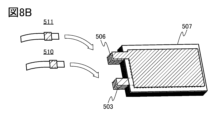
- Figures 7A and 7B have a positive electrode 503, a negative electrode 506, a separator 507, an exterior body 509, a positive electrode lead electrode 510, and a negative electrode lead electrode 511.
- a separator other than the separator of the separator-integrated electrode (negative electrode 506) may be included.
- FIG. 8A shows the external view of the positive electrode 503 and the negative electrode 506.
- the positive electrode 503 has a positive electrode current collector 501, and the positive electrode active material layer 502 is formed on the surface of the positive electrode current collector 501.
- the positive electrode 503 also has a region where the positive electrode current collector 501 is partially exposed (hereinafter referred to as the tab region).
- the negative electrode 506 has a negative electrode current collector 504, and the negative electrode active material layer 505 is formed on the surface of the negative electrode current collector 504.
- the negative electrode 506 also has a region where the negative electrode current collector 504 is partially exposed, i.e., the tab region. Note that the area or shape of the tab regions of the positive electrode and the negative electrode are not limited to the example shown in FIG. 8A.
- FIG. 8B shows the laminated negative electrode 506, separator 507, and positive electrode 503.
- an example is shown in which five pairs of negative electrodes and four pairs of positive electrodes are used. This can also be called a laminate consisting of a negative electrode, a separator, and a positive electrode.
- the tab regions of the positive electrodes 503 are bonded to each other, and the positive electrode lead electrode 510 is bonded to the tab region of the outermost positive electrode.
- ultrasonic welding or the like may be used for bonding.
- the tab regions of the negative electrodes 506 are bonded to each other, and the negative electrode lead electrode 511 is bonded to the tab region of the outermost negative electrode.
- the negative electrode 506, the separator 507, and the positive electrode 503 are placed on the exterior body 509.
- the exterior body 509 is folded at the portion indicated by the dashed line. After that, the outer periphery of the exterior body 509 is joined.
- the joining for example, thermocompression bonding or the like may be used.
- an area (hereinafter referred to as an inlet) that is not joined is provided on a part (or one side) of the exterior body 509 so that the electrolyte can be introduced later.
- the electrolyte is introduced into the inside of the exterior body 509 through an inlet provided in the exterior body 509.
- the electrolyte is preferably introduced in a reduced pressure atmosphere or an inert atmosphere.
- the inlet is joined. In this manner, the laminated secondary battery 500 can be produced.
- a lightweight secondary battery 500 can be obtained.
- Example of a battery pack An example of a secondary battery pack according to one embodiment of the present invention which can be wirelessly charged using an antenna will be described with reference to FIG.
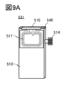
- FIG. 9A is a diagram showing the external appearance of secondary battery pack 531, which has a thin rectangular parallelepiped shape (also called a thick flat plate shape).
- FIG. 9B is a diagram explaining the configuration of secondary battery pack 531.
- Secondary battery pack 531 has circuit board 540 and secondary battery 513. Label 529 is affixed to secondary battery 513. Circuit board 540 is fixed with sticker 515. Secondary battery pack 531 also has antenna 517.
- the inside of the secondary battery 513 may have a structure with a wound body or a structure with a laminated body.
- a control circuit 590 is provided on a circuit board 540.
- the circuit board 540 is also electrically connected to the terminal 514.
- the circuit board 540 is also electrically connected to the antenna 517, one of the positive and negative leads 551, and the other of the positive and negative leads 552 of the secondary battery 513.
- the device may have a circuit system 590a provided on the circuit board 540 and a circuit system 590b electrically connected to the circuit board 540 via the terminal 514.
- the antenna 517 is not limited to a coil shape, and may be, for example, linear or plate-shaped. Also, antennas such as planar antennas, aperture antennas, traveling wave antennas, EH antennas, magnetic field antennas, and dielectric antennas may be used. Alternatively, the antenna 517 may be a flat conductor. This flat conductor can function as one of the conductors for electric field coupling. In other words, the antenna 517 may function as one of the two conductors of a capacitor. This allows power to be exchanged not only by electromagnetic fields and magnetic fields, but also by electric fields.
- the secondary battery pack 531 has a layer 519 between the antenna 517 and the secondary battery 513.
- the layer 519 has a function of, for example, blocking the electromagnetic field caused by the secondary battery 513.
- a magnetic material can be used as the layer 519.
- the secondary battery can be applied to automobiles, typically as a vehicle.
- automobiles include next-generation clean energy automobiles such as hybrid vehicles (HVs), electric vehicles (EVs), and plug-in hybrid vehicles (also called PHEVs or PHVs), and the secondary battery can be applied as one of the power sources mounted on the automobiles.
- the vehicle is not limited to automobiles.
- examples of vehicles include trains, monorails, ships, submersibles (deep-sea exploration vessels, unmanned submersibles), aircraft (helicopters, unmanned aerial vehicles (drones), airplanes, rockets, and artificial satellites), electric bicycles, and electric motorcycles, and the secondary battery of one embodiment of the present invention can be applied to these vehicles.
- the electric vehicle is equipped with first batteries 1301a and 1301b as main driving secondary batteries, and a second battery 1311 that supplies power to an inverter 1312 that starts a motor 1304.
- the second battery 1311 is also called a cranking battery (also called a starter battery).
- the second battery 1311 only needs to have high output, and does not need to have a large capacity, and the capacity of the second battery 1311 is smaller than that of the first batteries 1301a and 1301b.
- the internal structure of the first battery 1301a may be a wound type as shown in FIG. 5C or FIG. 6A, or a stacked type as shown in FIG. 7A or FIG. 7B.
- the first battery 1301a may use the all-solid-state battery of embodiment 6. By using the all-solid-state battery of embodiment 6 for the first battery 1301a, it is possible to achieve a high capacity, improve safety, and reduce the size and weight.
- first batteries 1301a, 1301b are connected in parallel, but three or more batteries may be connected in parallel. Also, if the first battery 1301a can store sufficient power, the first battery 1301b may not be necessary.
- a battery pack having multiple secondary batteries it is possible to extract large amounts of power.
- the multiple secondary batteries may be connected in parallel, in series, or in parallel and then further in series. Multiple secondary batteries are also called a battery pack.
- a service plug or circuit breaker that can cut off high voltage without using tools is provided in the first battery 1301a.
- the power of the first batteries 1301a and 1301b is mainly used to rotate the motor 1304, but also supplies power to 42V in-vehicle components (such as the electric power steering 1307, heater 1308, and defogger 1309) via the DCDC circuit 1306. If the vehicle has a rear motor 1317 on the rear wheels, the first battery 1301a is also used to rotate the rear motor 1317.
- the second battery 1311 also supplies power to 14V in-vehicle components (audio 1313, power windows 1314, lamps 1315, etc.) via the DCDC circuit 1310.
- FIG. 10A shows an example in which nine rectangular secondary batteries 1300 are used as one battery pack 1415.
- Nine rectangular secondary batteries 1300 are connected in series, one electrode is fixed by a fixing part 1413 made of an insulator, and the other electrode is fixed by a fixing part 1414 made of an insulator.
- the batteries are fixed by the fixing parts 1413 and 1414, but they may be stored in a battery storage box (also called a housing). Since it is assumed that the vehicle will be subjected to vibration or shaking from the outside (such as the road surface), it is preferable to fix multiple secondary batteries by the fixing parts 1413 and 1414 or a battery storage box.
- One electrode is electrically connected to the control circuit part 1320 by a wiring 1421.
- the other electrode is electrically connected to the control circuit part 1320 by a wiring 1422.
- the control circuit unit 1320 may also use a memory circuit including transistors using oxide semiconductors.
- a charge control circuit or a battery control system having a memory circuit including transistors using oxide semiconductors may be referred to as a BTOS (Battery operating system, or Battery oxide semiconductor).
- a metal oxide that functions as an oxide semiconductor it is preferable to use a metal oxide that functions as an oxide semiconductor.
- a metal oxide such as In-M-Zn oxide (wherein element M is one or more selected from aluminum, gallium, yttrium, copper, vanadium, beryllium, boron, titanium, iron, nickel, germanium, zirconium, molybdenum, lanthanum, cerium, neodymium, hafnium, tantalum, tungsten, magnesium, etc.) may be used as the metal oxide.
- the In-M-Zn oxide that can be used as the metal oxide is preferably CAAC-OS (C-Axis Aligned Crystal Oxide Semiconductor) or CAC-OS (Cloud-Aligned Composite Oxide Semiconductor). In-Ga oxide and In-Zn oxide may also be used as the metal oxide.
- CAAC-OS is an oxide semiconductor having multiple crystalline regions, each of which has a c-axis oriented in a specific direction. Note that the specific direction is the thickness direction of the CAAC-OS film, the normal direction to the surface on which the CAAC-OS film is formed, or the normal direction to the surface of the CAAC-OS film.
- the crystalline regions are regions in which the atomic arrangement has periodicity. Note that when the atomic arrangement is considered as a lattice arrangement, the crystalline regions are also regions in which the lattice arrangement is aligned.
- CAC-OS has a mosaic structure in which the material is separated into a first region and a second region, and the first region is distributed throughout the film (hereinafter, also referred to as a cloud structure).
- CAC-OS is a composite metal oxide having a structure in which the first region and the second region are mixed.
- it is difficult to observe a clear boundary between the first region and the second region there are cases in which it is difficult to observe a clear boundary between the first region and the second region.
- the structure has a mixture of a region mainly composed of In (first region) and a region mainly composed of Ga (second region) that are unevenly distributed.
- EDX energy dispersive X-ray spectroscopy
- the CAC-OS When the CAC-OS is used in a transistor, the conductivity due to the first region and the insulating property due to the second region act complementarily, so that the CAC-OS can be given a switching function (on/off function).
- the CAC-OS has a conductive function in a part of the material and an insulating function in a part of the material, and the whole material has a function as a semiconductor. By separating the conductive function and the insulating function, both functions can be maximized. Therefore, by using the CAC-OS in a transistor, a high on-current (I on ), a high field-effect mobility ( ⁇ ), and a good switching operation can be realized.
- Oxide semiconductors have a variety of structures, each with different characteristics.
- An oxide semiconductor according to one embodiment of the present invention may have two or more of an amorphous oxide semiconductor, a polycrystalline oxide semiconductor, an a-like OS, a CAC-OS, an nc-OS, and a CAAC-OS.
- the control circuit unit 1320 uses a transistor using an oxide semiconductor.
- the control circuit unit 1320 may be formed using a unipolar transistor.
- a transistor using an oxide semiconductor in the semiconductor layer has a wider operating ambient temperature range than a single-crystal Si transistor, from -40°C to 150°C, and the characteristic change is smaller than that of a single-crystal Si transistor even if the secondary battery overheats.
- the off-current of a transistor using an oxide semiconductor is below the lower measurement limit regardless of temperature, even at 150°C, but the off-current characteristic of a single-crystal Si transistor is highly temperature-dependent. For example, at 150°C, the off-current of a single-crystal Si transistor increases, and the current on/off ratio does not become sufficiently large.
- the control circuit unit 1320 can improve safety.
- the control circuit section 1320 which uses a memory circuit including transistors using oxide semiconductors, can also function as an automatic control device for the secondary battery to deal with causes of instability such as micro-shorts.
- Functions for eliminating causes of instability in the secondary battery include overcharging prevention, overcurrent prevention, overheating control during charging, cell balancing in the battery pack, over-discharging prevention, a remaining capacity gauge, automatic control of charging voltage and current amount according to temperature, control of charging current amount according to the degree of deterioration, detection of abnormal behavior of micro-shorts, and prediction of abnormalities related to micro-shorts, and at least one of these functions is provided by the control circuit section 1320.
- Micro-short refers to a tiny short circuit inside a secondary battery, not a short circuit between the positive and negative electrodes of the secondary battery that makes it impossible to charge or discharge, but a phenomenon in which a small amount of short-circuit current flows at the tiny short circuit. Even if it is only in a small location and for a relatively short period of time, a large voltage change occurs, and the abnormal voltage value may affect subsequent estimates.
- One of the causes of micro-short circuits is said to be that multiple charge and discharge cycles cause uneven distribution of the positive electrode active material, resulting in localized current concentration in parts of the positive electrode and negative electrode, causing parts of the separator to stop functioning, or the generation of by-products due to side reactions, resulting in micro-short circuits.
- control circuit section 1320 can also be said to detect the terminal voltage of the secondary battery and manage the charge/discharge state of the secondary battery. For example, to prevent overcharging, it can turn off both the output transistor and the cutoff switch of the charging circuit almost simultaneously.
- FIG. 10B An example of a block diagram of the battery pack 1415 shown in FIG. 10A is shown in FIG. 10B.
- the control circuit unit 1320 has at least a switch unit 1324 including a switch for preventing overcharging and a switch for preventing overdischarging, a control circuit 1322 for controlling the switch unit 1324, and a voltage measurement unit for the first battery 1301a.
- the control circuit unit 1320 is set with an upper limit voltage and a lower limit voltage for the secondary battery to be used, and limits the upper limit of the current from the outside or the upper limit of the output current to the outside.
- the range between the lower limit voltage and the upper limit voltage of the secondary battery is within the voltage range recommended for use, and when it is outside that range, the switch unit 1324 operates and functions as a protection circuit.
- control circuit unit 1320 can also be called a protection circuit because it controls the switch unit 1324 to prevent overcharging and/or overdischarging. For example, when the control circuit 1322 detects a voltage that is likely to cause overcharging, the switch unit 1324 is turned off to cut off the current. Furthermore, a PTC element may be provided in the charge/discharge path to provide a function for cutting off the current in response to a rise in temperature. In addition, the control circuit section 1320 has an external terminal 1325 (+IN) and an external terminal 1326 (-IN).
- the switch section 1324 can be configured by combining n-channel transistors or p-channel transistors.
- the switch section 1324 is not limited to a switch having a Si transistor using single crystal silicon, and may be formed of a power transistor having, for example, Ge (germanium), SiGe (silicon germanium), GaAs (gallium arsenide), GaAlAs (gallium aluminum arsenide), InP (indium phosphide), SiC (silicon carbide), ZnSe (zinc selenide), GaN (gallium nitride), GaOx (gallium oxide; x is a real number greater than 0), or the like.
- a memory element using an OS transistor can be freely arranged by stacking it on a circuit using a Si transistor, integration can be easily performed. Furthermore, since an OS transistor can be manufactured using the same manufacturing equipment as a Si transistor, it can be manufactured at low cost. That is, a control circuit section 1320 using an OS transistor can be stacked on the switch section 1324 and integrated into one chip. Since the volume occupied by the control circuit section 1320 can be reduced, miniaturization is possible.
- the first batteries 1301a and 1301b mainly supply power to 42V (high voltage HV) in-vehicle equipment, and the second battery 1311 supplies power to 14V (low voltage LV) in-vehicle equipment.
- Lead-acid batteries are often used as the second battery 1311 because of their cost advantage. Lead-acid batteries have a large self-discharge compared to lithium-ion batteries, and are prone to deterioration due to a phenomenon called sulfation.
- the advantage of using a lithium-ion battery as the second battery 1311 is that it is maintenance-free, but if it is used for a long period of time, for example, for more than three years, there is a risk of abnormalities occurring that are difficult to identify at the time of manufacture.
- the second battery 1311 that starts the inverter becomes inoperable, even if the first batteries 1301a and 1301b have remaining capacity, in order to prevent the motor from being unable to start, if the second battery 1311 is a lead-acid battery, power is supplied from the first battery to the second battery, and the battery is charged to always maintain a fully charged state.
- the second battery 1311 may be a lead-acid battery, an all-solid-state battery, or an electric double layer capacitor.
- the all-solid-state battery of embodiment 6 may be used.
- regenerative energy produced by the rotation of the tire 1316 is sent to the motor 1304 via the gear 1305, and is charged into the second battery 1311 via the motor controller 1303 or the battery controller 1302 via the control circuit unit 1321.
- the first battery 1301a is charged from the battery controller 1302 via the control circuit unit 1320.
- the first battery 1301b is charged from the battery controller 1302 via the control circuit unit 1320. In order to efficiently charge the regenerative energy, it is desirable that the first batteries 1301a and 1301b are capable of being charged quickly.
- the battery controller 1302 can set the charging voltage and charging current of the first batteries 1301a and 1301b.
- the battery controller 1302 can set charging conditions according to the charging characteristics of the secondary battery being used, and can perform rapid charging.
- the charger outlet or the charger connection cable is electrically connected to the battery controller 1302.
- the power supplied from the external charger is charged to the first batteries 1301a and 1301b via the battery controller 1302.
- Some chargers are provided with a control circuit and may not use the function of the battery controller 1302, but it is preferable to charge the first batteries 1301a and 1301b via the control circuit section 1320 to prevent overcharging.
- the charger outlet or the charger connection cable may be provided with a control circuit.
- the control circuit section 1320 may also be called an ECU (Electronic Control Unit).
- the ECU is connected to a CAN (Controller Area Network) provided in the electric vehicle.
- the CAN is one of the serial communication standards used as an in-vehicle LAN.
- the ECU also includes a microcomputer.
- the ECU also uses a CPU or GPU.
- External chargers installed at charging stations, etc. include 100V to 200V outlets, or three-phase 200V and 50kW. It is also possible to charge by receiving power from external charging equipment using a contactless power supply method, etc.
- the secondary battery of this embodiment described above can be provided as a lightweight secondary battery for vehicles by using the separator-integrated electrode described in embodiment 1 as the negative electrode.
- a next-generation clean energy vehicle such as a hybrid vehicle (HV), an electric vehicle (EV), or a plug-in hybrid vehicle (PHV) can be realized.
- the secondary battery can also be mounted on agricultural machinery, mopeds including electrically assisted bicycles, motorcycles, electric wheelchairs, electric carts, ships, submarines, aircraft, rockets, artificial satellites, space probes, planetary probes, or spacecraft.
- the secondary battery of one embodiment of the present invention can be a high-capacity secondary battery. Therefore, the secondary battery of one embodiment of the present invention is suitable for miniaturization and weight reduction, and can be suitably used in transportation vehicles.
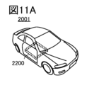
- the automobile 2001 shown in FIG. 11A is an electric automobile that uses an electric motor as a power source for running. Or, it is a hybrid automobile that can appropriately select and use an electric motor and an engine as a power source for running.
- a secondary battery is mounted on the vehicle, an example of the secondary battery shown in embodiment 4 is installed in one or more locations.
- the automobile 2001 shown in FIG. 11A has a battery pack 2200, which has a secondary battery module to which multiple secondary batteries are connected. It is further preferable to have a charging control device that is electrically connected to the secondary battery module.
- automobile 2001 can charge the secondary battery of automobile 2001 by receiving power supply from an external charging facility by a plug-in method or a contactless power supply method, etc.
- the charging method or connector standard may be a predetermined method such as CHAdeMO (registered trademark) or Combo, as appropriate.
- the charging facility may be a charging station provided in a commercial facility, or may be a home power source.
- the power storage device mounted on automobile 2001 can be charged by an external power supply. Charging can be performed by converting AC power to DC power via a conversion device such as an AC-DC converter.
- a power receiving device can be mounted on the vehicle and power can be supplied contactlessly from a power transmitting device on the ground for charging.
- this contactless power supply method by incorporating a power transmitting device into the road or an exterior wall, charging can be performed not only when the vehicle is stopped but also while it is moving.
- This contactless power supply method can also be used to transmit and receive power between two vehicles.
- solar cells can be installed on the exterior of the vehicle, and the secondary battery can be charged when the vehicle is stopped or moving.
- an electromagnetic induction method or a magnetic field resonance method can be used.
- FIG. 11B shows a large transport vehicle 2002 with an electrically controlled motor as an example of a transport vehicle.
- the secondary battery module of the transport vehicle 2002 is, for example, a four-cell unit of secondary batteries with a nominal voltage of 3.0V to 5.0V, with 48 cells connected in series to achieve a maximum voltage of 170V.
- the number of secondary batteries that make up the secondary battery module of the battery pack 2201 it has the same functions as FIG. 11A, so a description will be omitted.
- FIG. 11C shows, as an example, a large transport vehicle 2003 having an electrically controlled motor.
- the secondary battery module of the transport vehicle 2003 has a maximum voltage of 600V, for example, with more than 100 secondary batteries connected in series, each having a nominal voltage of 3.0V to 5.0V. Therefore, a secondary battery with small variation in characteristics is required.
- a secondary battery that uses the separator-integrated electrode described in embodiment 1 as the negative electrode a lightweight secondary battery can be provided as a secondary battery for vehicles.
- FIG. 11D shows, as an example, an aircraft 2004 with an engine that burns fuel.
- the aircraft 2004 shown in FIG. 11D has wheels for takeoff and landing, and can therefore be considered a type of transport vehicle. It has a battery pack 2203 that includes a secondary battery module formed by connecting multiple secondary batteries and a charging control device.
- the secondary battery module of the aircraft 2004 has a maximum voltage of 32V, for example, when eight 4V secondary batteries are connected in series. Other than the number of secondary batteries that make up the secondary battery module of the battery pack 2203, it has the same functions as those in FIG. 11A, so a description thereof will be omitted.
- FIG. 11E shows an example of a satellite 2005 equipped with a secondary battery 2204. Since the satellite 2005 is used in the extremely low temperatures of outer space, it is preferable that the satellite 2005 be equipped with a secondary battery 2204, which is an embodiment of the present invention and has excellent low temperature resistance. It is even more preferable that the secondary battery 2204 is mounted inside the satellite 2005 while being covered with a heat-retaining material.
- This embodiment can be used in combination with other embodiments.
- the house shown in FIG. 12A has a power storage device 2612 having a secondary battery which is one embodiment of the present invention, and a solar panel 2610.
- the power storage device 2612 is electrically connected to the solar panel 2610 via wiring 2611 or the like.
- the power storage device 2612 may also be electrically connected to a ground-mounted charging device 2604.
- the power obtained by the solar panel 2610 can be charged to the power storage device 2612.
- the power stored in the power storage device 2612 can also be charged to a secondary battery of the vehicle 2603 via the charging device 2604.
- the power storage device 2612 is preferably installed in the underfloor space. By installing the power storage device 2612 in the underfloor space, the space above the floor can be effectively utilized. Alternatively, the power storage device 2612 may be installed on the floor.
- the power stored in the power storage device 2612 can also be supplied to other electronic devices in the house. Therefore, even when power cannot be supplied from a commercial power source due to a power outage or the like, the power storage device 2612 according to one embodiment of the present invention can be used as an uninterruptible power source to enable the use of electronic devices.
- FIG. 12B shows an example of a power storage device according to one embodiment of the present invention.
- a power storage device 791 according to one embodiment of the present invention is installed in an underfloor space 796 of a building 799.
- the power storage device 791 is equipped with a control device 790, which is electrically connected by wiring to a distribution board 703, a power storage controller 705 (also called a control device), a display 706, and a router 709.
- a control device 790 which is electrically connected by wiring to a distribution board 703, a power storage controller 705 (also called a control device), a display 706, and a router 709.
- Power is sent from the commercial power source 701 to the distribution board 703 via the service line attachment part 710. Power is also sent to the distribution board 703 from the power storage device 791 and the commercial power source 701, and the distribution board 703 supplies the sent power to the general load 707 and the power storage load 708 via an outlet (not shown).
- the general load 707 is, for example, an electrical device such as a television or a personal computer
- the power storage load 708 is, for example, an electrical device such as a microwave oven, a refrigerator, or an air conditioner.
- the power storage controller 705 has a measurement unit 711, a prediction unit 712, and a planning unit 713.
- the measurement unit 711 has a function of measuring the amount of power consumed by the general load 707 and the power storage load 708 during a day (for example, from 0:00 to 24:00).
- the measurement unit 711 may also have a function of measuring the amount of power of the power storage device 791 and the amount of power supplied from the commercial power source 701.
- the prediction unit 712 has a function of predicting the amount of power demand to be consumed by the general load 707 and the power storage load 708 during the next day based on the amount of power consumed by the general load 707 and the power storage load 708 during a day.
- the planning unit 713 has a function of making a plan for charging and discharging the power storage device 791 based on the amount of power demand predicted by the prediction unit 712.
- the amount of power consumed by the general load 707 and the power storage load 708 measured by the measuring unit 711 can be confirmed on the display 706. It can also be confirmed on an electrical device such as a television or a personal computer via the router 709. It can also be confirmed on a portable electronic device such as a smartphone or a tablet via the router 709. The amount of power demand for each time period (or each hour) predicted by the prediction unit 712 can also be confirmed on the display 706, the electrical device, and the portable electronic device.
- This embodiment can be used in combination with other embodiments.
- FIG. 13A is an example of an electric bicycle using a power storage device of one embodiment of the present invention.
- the power storage device of one embodiment of the present invention can be applied to the electric bicycle 8700 shown in FIG. 13A.
- the power storage device of one embodiment of the present invention includes, for example, a plurality of storage batteries and a protection circuit.
- the electric bicycle 8700 includes a power storage device 8702.
- the power storage device 8702 can supply electricity to a motor that assists a rider.
- the power storage device 8702 is portable, and FIG. 13B shows the power storage device 8702 removed from the bicycle.
- the power storage device 8702 includes a plurality of built-in storage batteries 8701, which are included in the power storage device of one embodiment of the present invention, and the remaining battery charge and the like can be displayed on a display unit 8703.
- the power storage device 8702 also includes a control circuit 8704 that can control charging or detect an abnormality of the secondary battery, an example of which is shown in embodiment 7.
- the control circuit 8704 is electrically connected to the positive and negative electrodes of the storage battery 8701.
- FIG. 13C is an example of a two-wheeled vehicle using a power storage device of one embodiment of the present invention.
- a scooter 8600 shown in FIG. 13C includes a power storage device 8602, a side mirror 8601, and a turn signal light 8603.
- the power storage device 8602 can supply electricity to the turn signal light 8603.
- a lightweight secondary battery using the separator-integrated electrode described in embodiment 1 as a negative electrode can be provided as a secondary battery for a vehicle.
- the scooter 8600 shown in FIG. 13C can store the power storage device 8602 in the under-seat storage 8604.
- the power storage device 8602 can be stored in the under-seat storage 8604 even if the under-seat storage 8604 is small.
- This embodiment can be used in combination with other embodiments.
- FIG. 6 An example of mounting a secondary battery according to one embodiment of the present invention in an electronic device will be described.
- Examples of electronic devices mounting a secondary battery include television devices (also called televisions or television receivers), monitors for computers, digital cameras, digital video cameras, digital photo frames, mobile phones (also called mobile phones or mobile phone devices), portable game machines, portable information terminals, audio playback devices, and large game machines such as pachinko machines.
- Examples of portable information terminals include notebook personal computers, tablet terminals, e-book terminals, and mobile phones.
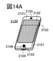
- FIG. 14A shows an example of a mobile phone.
- the mobile phone 2100 includes a display unit 2102 built into a housing 2101, as well as operation buttons 2103, an external connection port 2104, a speaker 2105, a microphone 2106, and the like.
- the mobile phone 2100 also includes a secondary battery 2107.
- a secondary battery 2107 that uses the separator-integrated electrode described in embodiment 1 as the negative electrode, a lightweight secondary battery can be provided as the secondary battery for a small electronic device.
- the mobile phone 2100 can execute a variety of applications, such as mobile phone calls, e-mail, text browsing and creation, music playback, Internet communication, and computer games.
- the operation button 2103 can have various functions, such as time setting, power on/off operation, wireless communication on/off operation, silent mode and power saving mode.
- the functions of the operation button 2103 can be freely set by an operating system built into the mobile phone 2100.
- the mobile phone 2100 is also capable of performing standardized short-range wireless communication. For example, it can communicate with a wireless headset to enable hands-free calling.
- the mobile phone 2100 also includes an external connection port 2104, and can directly exchange data with other information terminals via a connector. Charging can also be performed via the external connection port 2104. Note that charging may also be performed by wireless power supply without using the external connection port 2104.
- the mobile phone 2100 also preferably has a sensor.
- a sensor it is preferable to have a human body sensor such as a fingerprint sensor, a pulse sensor, a body temperature sensor, a touch sensor, a pressure sensor, an acceleration sensor, or the like.
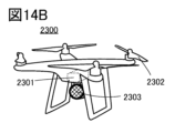
- FIG. 14B shows an unmanned aerial vehicle 2300 having multiple rotors 2302.
- the unmanned aerial vehicle 2300 is sometimes called a drone.
- the unmanned aerial vehicle 2300 has a secondary battery 2301, which is one embodiment of the present invention, a camera 2303, and an antenna (not shown).
- the unmanned aerial vehicle 2300 can be remotely controlled via the antenna.
- a secondary battery using the separator-integrated electrode described in embodiment 1 as a negative electrode has a high energy density and can be used for a long period of time, making it suitable as a secondary battery to be mounted on the unmanned aerial vehicle 2300.
- FIG. 14C shows an example of a robot.
- the robot 6400 shown in FIG. 14C includes a secondary battery 6409, an illuminance sensor 6401, a microphone 6402, an upper camera 6403, a speaker 6404, a display unit 6405, a lower camera 6406, an obstacle sensor 6407, a movement mechanism 6408, a computing device, etc.
- the microphone 6402 has a function of detecting the user's voice and environmental sounds.
- the speaker 6404 has a function of emitting sound.
- the robot 6400 can communicate with the user using the microphone 6402 and the speaker 6404.
- the display unit 6405 has a function of displaying various information.
- the robot 6400 can display information desired by the user on the display unit 6405.
- the display unit 6405 may be equipped with a touch panel.
- the display unit 6405 may also be a removable information terminal, and by installing it in a fixed position on the robot 6400, charging and data transfer are possible.
- the upper camera 6403 and the lower camera 6406 have the function of capturing images of the surroundings of the robot 6400.
- the obstacle sensor 6407 can detect the presence or absence of obstacles in the direction of travel when the robot 6400 moves forward using the moving mechanism 6408.
- the robot 6400 can recognize the surrounding environment and move safely using the upper camera 6403, the lower camera 6406, and the obstacle sensor 6407.
- the robot 6400 has a secondary battery 6409 according to one embodiment of the present invention and a semiconductor device or electronic component in its internal area.
- a secondary battery using the separator-integrated electrode described in the first and second embodiments as the negative electrode has a high energy density and can be used for a long period of time, making it suitable as the secondary battery 6409 to be mounted on the robot 6400.
- Figure 14D shows an example of a cleaning robot.
- the cleaning robot 6300 has a display unit 6302 arranged on the top surface of a housing 6301, multiple cameras 6303 arranged on the side, brushes 6304, operation buttons 6305, a secondary battery 6306, various sensors, and the like.
- the cleaning robot 6300 is equipped with tires, a suction port, and the like.
- the cleaning robot 6300 can move by itself, detect dirt 6310, and suck up the dirt from a suction port arranged on the bottom surface.
- the cleaning robot 6300 can analyze the image captured by the camera 6303 and determine whether or not there is an obstacle such as a wall, furniture, or a step. Furthermore, if an object that is likely to become entangled in the brush 6304, such as a wire, is detected by image analysis, the rotation of the brush 6304 can be stopped.
- the cleaning robot 6300 includes a secondary battery 6306 according to one embodiment of the present invention and a semiconductor device or electronic component in its internal area.
- a secondary battery using the separator-integrated electrode described in embodiments 1 and 2 as the negative electrode has a high energy density and can be used for a long period of time, and is suitable as the secondary battery 6306 to be mounted on the cleaning robot 6300.
- FIG 15A shows an example of a wearable device.
- Wearable devices use secondary batteries as a power source. Furthermore, when used by a user at home or outdoors, there is a demand for wearable devices that can be charged wirelessly as well as via wired charging with an exposed connector in order to improve splash-proof, water-resistant, or dust-proof performance.
- a secondary battery according to one embodiment of the present invention can be mounted on a glasses-type device 4000 as shown in FIG. 15A.
- the glasses-type device 4000 has a frame 4000a and a display unit 4000b.
- the glasses-type device 4000 can be made lightweight, well-balanced in weight, and capable of long continuous use.
- a secondary battery using the separator-integrated electrode described in embodiments 1 and 2 as the negative electrode has a high energy density, and can realize a configuration that can accommodate space saving associated with a smaller housing.
- the headset type device 4001 can be equipped with a secondary battery according to one embodiment of the present invention.
- the headset type device 4001 has at least a microphone section 4001a, a flexible pipe 4001b, and an earphone section 4001c.
- a secondary battery can be provided in the flexible pipe 4001b or in the earphone section 4001c.
- a secondary battery using the separator-integrated electrode described in embodiments 1 and 2 as the negative electrode has a high energy density, and can realize a configuration that can accommodate space saving associated with a smaller housing.
- a secondary battery according to one embodiment of the present invention can be mounted on a device 4002 that can be directly attached to the body.
- a secondary battery 4002b can be provided inside a thin housing 4002a of the device 4002.
- a secondary battery using the separator-integrated electrode described in embodiments 1 and 2 as the negative electrode has a high energy density, and can realize a configuration that can accommodate space saving associated with a smaller housing.
- a secondary battery according to one embodiment of the present invention can be mounted on a device 4003 that can be attached to clothing.
- a secondary battery 4003b can be provided inside a thin housing 4003a of the device 4003.
- a secondary battery using the separator-integrated electrode described in embodiments 1 and 2 as a negative electrode has a high energy density, and can realize a configuration that can accommodate space saving associated with a smaller housing.
- the belt-type device 4006 can be equipped with a secondary battery according to one embodiment of the present invention.
- the belt-type device 4006 has a belt portion 4006a and a wireless power receiving portion 4006b, and a secondary battery can be equipped in the internal area of the belt portion 4006a.
- a secondary battery using the separator-integrated electrode described in embodiments 1 and 2 as the negative electrode has a high energy density, and can realize a configuration that can accommodate space saving associated with the miniaturization of the housing.
- the secondary battery according to one embodiment of the present invention can be mounted on the wristwatch device 4005.
- the wristwatch device 4005 has a display portion 4005a and a belt portion 4005b, and a secondary battery can be provided on the display portion 4005a or the belt portion 4005b.
- a secondary battery using the separator-integrated electrode described in embodiments 1 and 2 as a negative electrode has a high energy density, and can realize a configuration that can accommodate space saving associated with miniaturization of the housing.
- the display unit 4005a can display not only the time, but also various other information such as incoming emails or phone calls.
- the wristwatch type device 4005 is a wearable device that is worn directly on the arm, it may be equipped with sensors that measure the user's pulse, blood pressure, etc. It can accumulate data on the user's amount of exercise and health, and manage the user's health.
- FIG. 15B shows an oblique view of the wristwatch device 4005 removed from the wrist.
- FIG. 15C shows a state in which a secondary battery 913 is built into the internal area.
- the secondary battery 913 is the secondary battery described in embodiment 4.
- the secondary battery 913 is provided in a position overlapping with the display portion 4005a, and can be made high density and high capacity, and is small and lightweight.
- the separator-integrated electrode described in the first and second embodiments can be used as the negative electrode to provide a high energy density and lightweight secondary battery 913.
- This embodiment can be used in combination with other embodiments.
- a separator-integrated electrode according to one embodiment of the present invention was created, and the strength and charge/discharge characteristics of the electrode were evaluated.
- Electrode 1 Electrode 2, and Electrode 3, which are separator-integrated electrodes according to one embodiment of the present invention, were fabricated with reference to the fabrication method described in Embodiment 1. Comparative electrodes 1 and 2 were also fabricated by the same fabrication method.
- the separator was fixed to a substrate and introduced into a sputtering deposition apparatus to deposit a silicon film.
- the silicon film was deposited using a 5N silicon (boron-doped) target with a diameter of 101.6 mm under the conditions of argon 40 sccm, pressure 0.4 Pa, and power 500 W (DC).
- the silicon film on the separator was deposited to a thickness of about 50 nm, which was designated as sample 1.
- Sample 2 Sample 3, Comparative Sample 1, and Comparative Sample 2 were prepared, which have silicon film thicknesses different from Sample 1.
- Sample 2 was prepared by depositing the silicon film on the separator until it was approximately 100 nm thick.
- Sample 3 was prepared by depositing the silicon film on the separator until it was approximately 200 nm thick.
- Comparative Sample 1 was prepared by depositing the silicon film on the separator until it was approximately 10 nm thick.
- Comparative Sample 2 was prepared by depositing the silicon film on the separator until it was approximately 20 nm thick.
- a carbon particle layer (graphite layer) was formed on the silicon layer in each of Sample 1, Sample 2, Sample 3, Comparative Sample 1, and Comparative Sample 2.
- the carbon particle layer was formed by a blade coating method.
- a carbon particle layer was provided on each of Sample 1, Sample 2, Sample 3, Comparative Sample 1, and Comparative Sample 2 using the method described above.
- Sample 1 after the carbon particle layer was provided is called electrode 1
- Sample 2 after the carbon particle layer was provided is called electrode 2
- Sample 3 after the carbon particle layer was provided is called electrode 3
- Comparative Sample 1 after the carbon particle layer was provided is called comparative electrode 1
- Comparative Sample 2 after the carbon particle layer was provided is called comparative electrode 2.
- Figures 16A, 16B, 16C, and 16D Photographs of the electrodes after punching into a circular shape are shown in Figures 16A, 16B, 16C, and 16D.
- Figure 16A shows a photograph of comparative electrode 2 (silicon layer 20 nm) after punching
- Figure 16B shows a photograph of electrode 1 (silicon layer 50 nm) after punching
- Figure 16C shows a photograph of electrode 2 (silicon layer 100 nm) after punching
- Figure 16D shows a photograph of electrode 3 (silicon layer 200 nm) after punching.
- the separator-integrated electrode punched out from electrode 1 is called electrode 1A.
- the separator-integrated electrode punched out from electrode 2 is called electrode 2A.
- the separator-integrated electrode punched out from electrode 3 is called electrode 3A.
- the separator-integrated electrode punched out from comparison electrode 2 is called comparison electrode 2A.
- Electrode 1A, Electrode 2A, Electrode 3A and Comparative Electrode 2A were used as positive electrodes to fabricate coin-type batteries of CR2032 type (diameter 20 mm, height 3.2 mm).
- Lithium metal foil was used as the counter electrode (negative electrode of the coin-type battery).
- a glass fiber sheet (thickness 260 ⁇ m, pore size 1.2 ⁇ m) was placed between the counter electrode and the above electrodes (electrode 1A, electrode 2A, electrode 3A, and comparison electrode 2A).
- EC ethylene carbonate
- DEC diethyl carbonate
- the positive and negative electrode cans were made of stainless steel (SUS).
- the coin-type battery made using electrode 1A is called cell 1.
- the coin-type battery made using electrode 2A is called cell 2.
- the coin-type battery made using electrode 3A is called cell 3.
- the coin-type battery made using comparative electrode 2A is called comparative cell 2.
- FIG. 17A is a graph showing the charging and discharging results of cell 1 (silicon layer 50 nm), where charging and discharging were possible.
- FIG. 17B is a graph showing the charging and discharging results of cell 2 (silicon layer 100 nm), where charging and discharging were possible.
- FIG. 17C is a graph showing the charging and discharging results of cell 3 (silicon layer 200 nm), where charging and discharging were possible.
- the discharge curve of cell 1 was on the lower voltage side than cells 2 and 3. Also, the charge curve of cell 1 was on the higher voltage side than cells 2 and 3. In other words, the internal resistance (also called reaction resistance) of cell 1 is considered to be higher than the internal resistance of cells 2 and 3.
- cell 2 in which the silicon layer is 100 nm thick
- cell 3 in which the silicon layer is 200 nm thick
- the silicon layer it is desirable for the silicon layer to have a thickness of 100 nm or more and 200 nm or less.
Landscapes
- Chemical & Material Sciences (AREA)
- Chemical Kinetics & Catalysis (AREA)
- Electrochemistry (AREA)
- General Chemical & Material Sciences (AREA)
- Engineering & Computer Science (AREA)
- Materials Engineering (AREA)
- Manufacturing & Machinery (AREA)
- Inorganic Chemistry (AREA)
- Battery Electrode And Active Subsutance (AREA)
- Secondary Cells (AREA)
Abstract
Description
図2A乃至図2Cは、セパレータ一体型電極を有する電池の構造を説明する図である。
図3A乃至図3Cは、セパレータ一体型電極の構造の変形例を説明する図である。
図4Aは、円筒型の二次電池の例を示す。図4Bは、円筒型の二次電池の例を示す。図4Cは、複数の円筒型の二次電池の例を示す。図4Dは、複数の円筒型の二次電池を有する蓄電システムの例を示す。
図5A及び図5Bは、二次電池の例を説明する図であり、図5Cは、二次電池の内部の様子を示す図である。
図6A乃至図6Cは、二次電池の例を説明する図である。
図7A、及び図7Bは、二次電池の外観を示す図である。
図8A乃至図8Cは、二次電池の作製方法を説明する図である。
図9Aは、電池パックの構成例を示し、図9Bは、電池パックの構成例を示し、図9Cは、電池パックの構成例を示す。
図10Aは、本発明の一態様を示す電池パックの斜視図であり、図10Bは、電池パックのブロック図であり、図10Cは、電池パックを有する車両のブロック図である。
図11A乃至図11Dは、輸送用車両の一例を説明する図である。図11Eは、人工衛星の一例を説明する図である。
図12A、及び図12Bは、本発明の一態様に係る蓄電装置を説明する図である。
図13Aは、電動自転車を示す図であり、図13Bは、電動自転車の二次電池を示す図であり、図13Cは、スクータを説明する図である。
図14A乃至図14Dは、電子機器の一例を説明する図である。
図15Aは、ウェアラブルデバイスの例を示しており、図15Bは、腕時計型デバイスの斜視図を示しており、図15Cは、腕時計型デバイスの側面を説明する図である。
図16A乃至図16Dは、実施例1で説明するSEM像である。
図17A乃至図17Cは、実施例1で説明する充放電特性のグラフである。
本発明の一態様は、セパレータと、電極と、が一体となった構造を有する。当該構造をセパレータと一体化した電極と呼称してもよい。なお、本実施の形態では、セパレータと一体化した電極の構成、及びその作製方法について説明する。本明細書において、セパレータと一体化した電極を、セパレータ一体型電極と呼ぶ。
本実施の形態では、先の実施の形態で説明した作製方法によって作製されたセパレータ一体型電極を負極として有する二次電池に関し、形状の例を説明する。
円筒型の二次電池の例について図4Aを参照して説明する。円筒型の二次電池616は、図4Aに示すように、上面に正極キャップ(電池蓋)601を有し、側面及び底面に電池缶(外装缶)602を有している。これら正極キャップ601と電池缶(外装缶)602とは、ガスケット(絶縁パッキン)610によって絶縁されている。
セパレータ一体型電極を負極として有する二次電池の別の構造例について図5及び図6を用いて説明する。
次に、セパレータ一体型電極を負極として有するラミネート型の二次電池の例について、外観図の一例を図7A及び図7Bに示す。図7A及び図7Bは、正極503、負極506、セパレータ507、外装体509、正極リード電極510、及び負極リード電極511を有する。このように、セパレータ一体型電極(負極506)が有するセパレータとは別のセパレータを有していてもよい。
図7Aに外観図を示すラミネート型二次電池の作製方法の一例について、図8B及び図8Cを用いて説明する。
アンテナを用いて無線充電が可能な本発明の一態様の二次電池パックの例について、図9を用いて説明する。
本実施の形態では、本発明の一態様の二次電池を有する車両の例を示す。
本実施の形態では、本発明の一態様である二次電池を建築物に実装する例について図12A及び図12Bを用いて説明する。
本実施の形態では、二次電池を車両に搭載する一例として、二輪車、自転車に本発明の一態様であるリチウムイオン電池を搭載する例を示す。
本実施の形態では、本発明の一態様である二次電池を電子機器に実装する例について説明する。二次電池を実装する電子機器として、例えば、テレビジョン装置(テレビ、又はテレビジョン受信機ともいう)、コンピュータ用などのモニタ、デジタルカメラ、デジタルビデオカメラ、デジタルフォトフレーム、携帯電話機(携帯電話、携帯電話装置ともいう)、携帯型ゲーム機、携帯情報端末、音響再生装置、パチンコ機などの大型ゲーム機などが挙げられる。携帯情報端末としてはノート型パーソナルコンピュータ、タブレット型端末、電子書籍端末、携帯電話機などがある。
本発明の一態様のセパレータ一体型電極である電極1、電極2、及び電極3、を、実施の形態1に示した作製方法を参照し、作製した。また、同様の作製方法にて、比較電極1、及び比較電極2を作製した。
電極1、電極2、電極3、比較電極1、及び比較電極2の作製として、まずセパレータを用意した。セパレータは、厚み25μmのPP(ポリプロピレン)セパレータを用いた。
次に、上記のセパレータを基板に固定し、スパッタリング成膜装置に導入し、シリコン膜の成膜を行った。シリコン膜の成膜は、直径101.6mmの5Nシリコン(ボロンドープ)ターゲットを用いて、アルゴン40sccm、圧力0.4Pa、電力500W(DC)の条件でおこなった。上記セパレータ上のシリコン膜が約50nmの厚さになるまで成膜したものを、サンプル1とした。
次に、サンプル1、サンプル2、サンプル3、比較サンプル1、及び比較サンプル2のそれぞれにおいて、シリコン層上に炭素粒子層(黒鉛層)を作製した。炭素粒子層は、ブレード塗工法によって作製した。
次に、電極1、電極2、電極3、比較電極1、及び比較電極2の打ち抜き強度を調査した。電極1、電極2、電極3、比較電極1、及び比較電極2のそれぞれを、直径12mmの円形に打抜いた結果を、表1に示す。なお、比較電極1は、打ち抜き前に炭素粒子層が全て剥がれたため、打ち抜きを行わなかった。

次に、電極1A、電極2A、電極3A、および比較電極2Aを正極として用いて、CR2032タイプ(直径20mm高さ3.2mm)のコイン型の電池を作製した。
上記で作製したセル1、セル2、セル3、及び比較セル2の充放電特性を調査した。充放電特性の測定は、放電から開始した。放電をCCCV(定電流定電圧)、0.2C、0.01V、カットオフ電流0.02Cで行った。次に充電をCC(定電流)、0.2C、カットオフ電圧1.0Vで行った。なお、ここでの1Cは、黒鉛重量あたりの電流値として0.035mA/gとした。測定温度は25℃とした。
Claims (7)
- セパレータ一体型電極を有し、
前記セパレータ一体型電極は、セパレータと、炭素粒子層と、前記セパレータ及び前記炭素粒子層の間に位置するシリコン層と、を有する、電池。 - セパレータ一体型電極と、外装体と、を有し、
前記セパレータ一体型電極は、セパレータと、炭素粒子層と、前記セパレータ及び前記炭素粒子層の間に位置するシリコン層と、を有し、
前記炭素粒子層と前記外装体は、接する領域を有する、電池。 - 請求項1又は請求項2において、
前記シリコン層の厚さは、100nm以上200nm以下である、電池。 - 請求項1または請求項2において、
前記セパレータは、ポリプロピレンを有する、電池。 - セパレータと、炭素粒子層と、前記セパレータ及び前記炭素粒子層の間に位置するシリコン層と、を有するセパレータ一体型電極を備えた電池の作製方法であって、
前記セパレータの上に、スパッタリング法を用いて前記シリコン層を作製する第1の工程と、
前記シリコン層の上に、炭素粒子を有するスラリーを塗布することで前記炭素粒子層を作製する第2の工程と、を有し、
前記シリコン層の厚さは、100nm以上200nm以下である、電池の作製方法。 - 請求項5において、
前記スラリーは、N−メチル−ピロリドンを有する、電池の作製方法。 - 請求項5または請求項6において、
前記セパレータは、ポリプロピレンを有する、電池の作製方法。
Priority Applications (3)
| Application Number | Priority Date | Filing Date | Title |
|---|---|---|---|
| KR1020257008165A KR20250093295A (ko) | 2022-10-21 | 2023-10-16 | 전지 및 전지의 제작 방법 |
| JP2024550929A JPWO2024084367A1 (ja) | 2022-10-21 | 2023-10-16 | |
| CN202380068203.1A CN119923727A (zh) | 2022-10-21 | 2023-10-16 | 电池及电池的制造方法 |
Applications Claiming Priority (2)
| Application Number | Priority Date | Filing Date | Title |
|---|---|---|---|
| JP2022168996 | 2022-10-21 | ||
| JP2022-168996 | 2022-10-21 |
Publications (1)
| Publication Number | Publication Date |
|---|---|
| WO2024084367A1 true WO2024084367A1 (ja) | 2024-04-25 |
Family
ID=90737056
Family Applications (1)
| Application Number | Title | Priority Date | Filing Date |
|---|---|---|---|
| PCT/IB2023/060396 Ceased WO2024084367A1 (ja) | 2022-10-21 | 2023-10-16 | 電池及び電池の作製方法 |
Country Status (4)
| Country | Link |
|---|---|
| JP (1) | JPWO2024084367A1 (ja) |
| KR (1) | KR20250093295A (ja) |
| CN (1) | CN119923727A (ja) |
| WO (1) | WO2024084367A1 (ja) |
Citations (3)
| Publication number | Priority date | Publication date | Assignee | Title |
|---|---|---|---|---|
| KR20060020904A (ko) * | 2004-09-01 | 2006-03-07 | 브이케이 주식회사 | 적층형 리튬 이차 전지 및 그 제조방법 |
| JP2007172960A (ja) * | 2005-12-21 | 2007-07-05 | Samsung Sdi Co Ltd | リチウム二次電池及びリチウム二次電池の製造方法、セパレータ |
| CN114335900A (zh) * | 2021-12-30 | 2022-04-12 | 珠海冠宇电池股份有限公司 | 一种隔膜及含有该隔膜的电池 |
Family Cites Families (1)
| Publication number | Priority date | Publication date | Assignee | Title |
|---|---|---|---|---|
| US20150111107A1 (en) | 2013-10-22 | 2015-04-23 | Semiconductor Energy Laboratory Co., Ltd. | Electrode and secondary battery, and manufacturing method thereof |
-
2023
- 2023-10-16 KR KR1020257008165A patent/KR20250093295A/ko active Pending
- 2023-10-16 JP JP2024550929A patent/JPWO2024084367A1/ja active Pending
- 2023-10-16 CN CN202380068203.1A patent/CN119923727A/zh active Pending
- 2023-10-16 WO PCT/IB2023/060396 patent/WO2024084367A1/ja not_active Ceased
Patent Citations (3)
| Publication number | Priority date | Publication date | Assignee | Title |
|---|---|---|---|---|
| KR20060020904A (ko) * | 2004-09-01 | 2006-03-07 | 브이케이 주식회사 | 적층형 리튬 이차 전지 및 그 제조방법 |
| JP2007172960A (ja) * | 2005-12-21 | 2007-07-05 | Samsung Sdi Co Ltd | リチウム二次電池及びリチウム二次電池の製造方法、セパレータ |
| CN114335900A (zh) * | 2021-12-30 | 2022-04-12 | 珠海冠宇电池股份有限公司 | 一种隔膜及含有该隔膜的电池 |
Also Published As
| Publication number | Publication date |
|---|---|
| JPWO2024084367A1 (ja) | 2024-04-25 |
| KR20250093295A (ko) | 2025-06-24 |
| CN119923727A (zh) | 2025-05-02 |
Similar Documents
| Publication | Publication Date | Title |
|---|---|---|
| JP7851735B2 (ja) | 正極活物質の作製方法 | |
| JP2025168372A (ja) | 蓄電システム | |
| WO2021181191A1 (ja) | 二次電池、二次電池の作製方法、電子機器および車両 | |
| TW202218223A (zh) | 二次電池的製造方法及二次電池 | |
| JP2026063222A (ja) | 二次電池および電子機器 | |
| JP2026001108A (ja) | 二次電池の作製方法 | |
| JP2026035793A (ja) | 二次電池 | |
| US20230299280A1 (en) | Secondary battery, electronic device, and vehicle | |
| US20230343952A1 (en) | Secondary battery, manufacturing method of secondary battery, electronic device, and vehicle | |
| US20250309396A1 (en) | Power storage module | |
| KR20250093295A (ko) | 전지 및 전지의 제작 방법 | |
| WO2023047234A1 (ja) | 複合酸化物の作製方法、及びリチウムイオン電池の作製方法 | |
| CN116547882A (zh) | 蓄电系统、车辆以及电子设备 | |
| WO2022130099A1 (ja) | 二次電池、電子機器、蓄電システムおよび車両 | |
| US20250385535A1 (en) | Method for charging battery | |
| JP2022035302A (ja) | 二次電池およびその作製方法、および車両 | |
| JP7837868B2 (ja) | 二次電池および二次電池の作製方法 | |
| WO2025104567A1 (ja) | 二次電池、電子機器、車両、船舶、二次電池の作製方法、正極活物質の作製方法および賦活化球状多孔質炭素の作製方法 | |
| WO2025229468A1 (ja) | 負極活物質の作製方法 | |
| WO2026069096A1 (ja) | 正極、正極の作製方法 | |
| WO2023199158A1 (ja) | 蓄電モジュール | |
| WO2024150081A1 (ja) | 正極活物質の作製方法 | |
| JP2022107169A (ja) | 正極活物質の作製方法 | |
| JP2025085629A (ja) | 二次電池 | |
| WO2024003654A1 (ja) | 二次電池の充電管理システム |
Legal Events
| Date | Code | Title | Description |
|---|---|---|---|
| 121 | Ep: the epo has been informed by wipo that ep was designated in this application |
Ref document number: 23879297 Country of ref document: EP Kind code of ref document: A1 |
|
| WWE | Wipo information: entry into national phase |
Ref document number: 202380068203.1 Country of ref document: CN |
|
| WWE | Wipo information: entry into national phase |
Ref document number: 2024550929 Country of ref document: JP |
|
| WWP | Wipo information: published in national office |
Ref document number: 202380068203.1 Country of ref document: CN |
|
| NENP | Non-entry into the national phase |
Ref country code: DE |
|
| WWP | Wipo information: published in national office |
Ref document number: 1020257008165 Country of ref document: KR |
|
| 122 | Ep: pct application non-entry in european phase |
Ref document number: 23879297 Country of ref document: EP Kind code of ref document: A1 |