WO2024075750A1 - 炭化水素生成システム及び二酸化炭素循環システム - Google Patents
炭化水素生成システム及び二酸化炭素循環システム Download PDFInfo
- Publication number
- WO2024075750A1 WO2024075750A1 PCT/JP2023/036113 JP2023036113W WO2024075750A1 WO 2024075750 A1 WO2024075750 A1 WO 2024075750A1 JP 2023036113 W JP2023036113 W JP 2023036113W WO 2024075750 A1 WO2024075750 A1 WO 2024075750A1
- Authority
- WO
- WIPO (PCT)
- Prior art keywords
- hydrocarbon production
- heat
- hydrocarbon
- heat exchanger
- steam
- Prior art date
- Legal status (The legal status is an assumption and is not a legal conclusion. Google has not performed a legal analysis and makes no representation as to the accuracy of the status listed.)
- Ceased
Links
Images



Classifications
-
- C—CHEMISTRY; METALLURGY
- C25—ELECTROLYTIC OR ELECTROPHORETIC PROCESSES; APPARATUS THEREFOR
- C25B—ELECTROLYTIC OR ELECTROPHORETIC PROCESSES FOR THE PRODUCTION OF COMPOUNDS OR NON-METALS; APPARATUS THEREFOR
- C25B15/00—Operating or servicing cells
- C25B15/08—Supplying or removing reactants or electrolytes; Regeneration of electrolytes
- C25B15/081—Supplying products to non-electrochemical reactors that are combined with the electrochemical cell, e.g. Sabatier reactor
-
- C—CHEMISTRY; METALLURGY
- C01—INORGANIC CHEMISTRY
- C01B—NON-METALLIC ELEMENTS; COMPOUNDS THEREOF; METALLOIDS OR COMPOUNDS THEREOF NOT COVERED BY SUBCLASS C01C
- C01B32/00—Carbon; Compounds thereof
- C01B32/50—Carbon dioxide
-
- C—CHEMISTRY; METALLURGY
- C07—ORGANIC CHEMISTRY
- C07C—ACYCLIC OR CARBOCYCLIC COMPOUNDS
- C07C1/00—Preparation of hydrocarbons from one or more compounds, none of them being a hydrocarbon
- C07C1/02—Preparation of hydrocarbons from one or more compounds, none of them being a hydrocarbon from oxides of a carbon
- C07C1/12—Preparation of hydrocarbons from one or more compounds, none of them being a hydrocarbon from oxides of a carbon from carbon dioxide with hydrogen
-
- C—CHEMISTRY; METALLURGY
- C10—PETROLEUM, GAS OR COKE INDUSTRIES; TECHNICAL GASES CONTAINING CARBON MONOXIDE; FUELS; LUBRICANTS; PEAT
- C10L—FUELS NOT OTHERWISE PROVIDED FOR; NATURAL GAS; SYNTHETIC NATURAL GAS OBTAINED BY PROCESSES NOT COVERED BY SUBCLASSES C10G OR C10K; LIQUIFIED PETROLEUM GAS; USE OF ADDITIVES TO FUELS OR FIRES; FIRE-LIGHTERS
- C10L3/00—Gaseous fuels; Natural gas; Synthetic natural gas obtained by processes not covered by subclass C10G, C10K; Liquefied petroleum gas
- C10L3/06—Natural gas; Synthetic natural gas obtained by processes not covered by C10G, C10K3/02 or C10K3/04
- C10L3/08—Production of synthetic natural gas
-
- C—CHEMISTRY; METALLURGY
- C25—ELECTROLYTIC OR ELECTROPHORETIC PROCESSES; APPARATUS THEREFOR
- C25B—ELECTROLYTIC OR ELECTROPHORETIC PROCESSES FOR THE PRODUCTION OF COMPOUNDS OR NON-METALS; APPARATUS THEREFOR
- C25B1/00—Electrolytic production of inorganic compounds or non-metals
- C25B1/01—Products
- C25B1/02—Hydrogen or oxygen
- C25B1/04—Hydrogen or oxygen by electrolysis of water
- C25B1/042—Hydrogen or oxygen by electrolysis of water by electrolysis of steam
-
- C—CHEMISTRY; METALLURGY
- C25—ELECTROLYTIC OR ELECTROPHORETIC PROCESSES; APPARATUS THEREFOR
- C25B—ELECTROLYTIC OR ELECTROPHORETIC PROCESSES FOR THE PRODUCTION OF COMPOUNDS OR NON-METALS; APPARATUS THEREFOR
- C25B15/00—Operating or servicing cells
- C25B15/02—Process control or regulation
- C25B15/021—Process control or regulation of heating or cooling
-
- C—CHEMISTRY; METALLURGY
- C25—ELECTROLYTIC OR ELECTROPHORETIC PROCESSES; APPARATUS THEREFOR
- C25B—ELECTROLYTIC OR ELECTROPHORETIC PROCESSES FOR THE PRODUCTION OF COMPOUNDS OR NON-METALS; APPARATUS THEREFOR
- C25B15/00—Operating or servicing cells
- C25B15/08—Supplying or removing reactants or electrolytes; Regeneration of electrolytes
-
- C—CHEMISTRY; METALLURGY
- C10—PETROLEUM, GAS OR COKE INDUSTRIES; TECHNICAL GASES CONTAINING CARBON MONOXIDE; FUELS; LUBRICANTS; PEAT
- C10L—FUELS NOT OTHERWISE PROVIDED FOR; NATURAL GAS; SYNTHETIC NATURAL GAS OBTAINED BY PROCESSES NOT COVERED BY SUBCLASSES C10G OR C10K; LIQUIFIED PETROLEUM GAS; USE OF ADDITIVES TO FUELS OR FIRES; FIRE-LIGHTERS
- C10L2290/00—Fuel preparation or upgrading, processes or apparatus therefore, comprising specific process steps or apparatus units
- C10L2290/06—Heat exchange, direct or indirect
-
- C—CHEMISTRY; METALLURGY
- C10—PETROLEUM, GAS OR COKE INDUSTRIES; TECHNICAL GASES CONTAINING CARBON MONOXIDE; FUELS; LUBRICANTS; PEAT
- C10L—FUELS NOT OTHERWISE PROVIDED FOR; NATURAL GAS; SYNTHETIC NATURAL GAS OBTAINED BY PROCESSES NOT COVERED BY SUBCLASSES C10G OR C10K; LIQUIFIED PETROLEUM GAS; USE OF ADDITIVES TO FUELS OR FIRES; FIRE-LIGHTERS
- C10L2290/00—Fuel preparation or upgrading, processes or apparatus therefore, comprising specific process steps or apparatus units
- C10L2290/42—Fischer-Tropsch steps
Definitions
- the present disclosure relates to a hydrocarbon production system having a hydrocarbon production device and an electrolysis device, and a carbon dioxide circulation system equipped with the same.
- Methanation which uses the Sabatier reaction to produce methane from carbon dioxide and hydrogen, is known as a method for producing hydrocarbons.
- a technology for producing hydrogen through the electrolysis of water vapor is known as a method for producing hydrogen.
- Patent Document 1 proposes a technology that uses hydrogen obtained by electrolysis for methanation. According to Patent Document 1, since methanation is an exothermic reaction, it is possible to improve thermal energy efficiency by using the reaction heat to generate hydrogen.
- the amount of heat required to heat 4 mol of water at 25°C to 100°C and boil it to obtain steam at 100°C i.e., the amount of heat required for the reaction of formula (1)
- the amount of heat required for the reaction of formula (1) is 185 kJ, which is greater than the amount of heat generated in the Sabatier reaction (i.e., the amount of reaction heat generated in formula (3)), 165 kJ.
- the heat of reaction cannot cover the heat required to obtain steam from water.
- the amount of heat generated in a hydrocarbon production reaction such as methanation varies depending on the amount of hydrocarbon produced. Therefore, the amount of heat supplied from the outside must be adjusted to match the amount of heat generated in the hydrocarbon production reaction, making it difficult to control the amount of heat supplied.
- the present disclosure aims to provide a hydrocarbon production system capable of producing hydrocarbons while stably performing heat exchange, and a carbon dioxide circulation system that utilizes the hydrocarbon production system.
- One aspect of the present disclosure is a hydrocarbon production device for producing hydrocarbons by an exothermic reaction of carbon oxide gas and hydrogen; an electrolysis device that generates hydrogen from raw steam to be supplied to the hydrocarbon generation device; a steam supply line that evaporates the raw material liquid water to generate the raw material steam and supplies the raw material steam to the electrolysis device; a heat exchanger that utilizes reaction heat generated in the hydrocarbon production apparatus for evaporating the raw material liquid water in the steam supply line via a heat transfer oil;
- the hydrocarbon production system includes:
- a hydrocarbon production system as described above, comprising: a combustion furnace that uses hydrocarbons as fuel and emits carbon dioxide; a carbon dioxide supply line for supplying the carbon dioxide discharged from the combustion furnace as the carbon oxide gas to the hydrocarbon production device of the hydrocarbon production system; a hydrocarbon supply line that supplies the hydrocarbons produced from the hydrocarbon production device to the combustion furnace;
- the carbon dioxide circulation system is configured so that the amount of hydrocarbons produced in the hydrocarbon production device is adjusted according to the operating state of the combustion furnace.
- the hydrocarbon production system includes a hydrocarbon production device, an electrolysis device, a steam supply line, and a heat exchanger.
- the heat exchanger uses the reaction heat generated in the hydrocarbon production device to evaporate the raw liquid water in the steam supply line.
- the reaction heat is used to evaporate the raw liquid water via heat transfer oil.
- thermal oil Since thermal oil has a large heat capacity, it is possible to increase the amount of heat retained after heat recovery by heat exchange. Therefore, when the amount of heat generated in the hydrocarbon production reaction is large, the thermal oil can recover sufficient reaction heat, and this reaction heat can be used to evaporate the raw liquid water in the steam supply line. On the other hand, since the thermal oil can store sufficient reaction heat, even if the amount of reaction heat generated in the hydrocarbon production reaction fluctuates and the amount of heat generated becomes low or becomes zero, for example, the heat retained by the thermal oil can be supplied to the raw liquid water in the steam supply line and used to evaporate the raw liquid water. In the above-mentioned hydrocarbon production system, heat exchange is performed stably even if the amount of reaction heat fluctuates.
- the carbon dioxide circulation system includes a hydrocarbon production system, a combustion furnace, a carbon dioxide supply line, and a hydrocarbon supply line.
- hydrocarbons are produced by an exothermic reaction between carbon oxide gases such as carbon dioxide and hydrogen.
- the hydrocarbons are supplied to the combustion furnace by the hydrocarbon supply line.
- carbon dioxide is emitted by burning the hydrocarbons.
- the carbon dioxide is supplied to the hydrocarbon production device of the hydrocarbon production system by the carbon dioxide supply line.
- carbon dioxide circulation system carbon dioxide circulates between the hydrocarbon production system and the combustion furnace. This makes it possible to build a so-called carbon-neutral system in which greenhouse gas emissions are suppressed.
- the carbon dioxide circulation system is configured to adjust the amount of hydrocarbons produced in the hydrocarbon production device according to the operating state of the combustion furnace. As a result, even if the required amount of hydrocarbons fluctuates according to the operating state of the combustion furnace, the hydrocarbon production system can produce hydrocarbons according to the fluctuation and supply them to the combustion furnace.
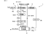
- FIG. 1 is a block diagram showing a main configuration of a hydrocarbon production system according to a first embodiment
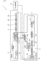
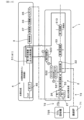
- FIG. 2 is a block diagram showing a hydrocarbon production system for producing hydrocarbons using carbon dioxide and hydrogen in embodiment 1
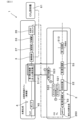
- FIG. 3 is a block diagram showing a hydrocarbon production system for producing hydrocarbons using carbon monoxide and hydrogen in embodiment 1
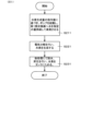
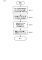
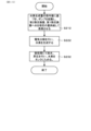
- FIG. 4 is an operational flow diagram showing a start-up process of the hydrocarbon production system in the first embodiment
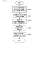
- FIG. 5 is an operation flow diagram of hydrogen production control of the hydrocarbon production system in embodiment 1
- FIG. 6 is an operation flow diagram of the hydrocarbon production system in the first embodiment
- FIG. 1 is a block diagram showing a main configuration of a hydrocarbon production system according to a first embodiment
- FIG. 2 is a block diagram showing a hydrocarbon production system for producing hydrocarbons using carbon dioxide and hydrogen in embodiment 1
- FIG. 3 is a block diagram showing a hydrocarbon production system for producing hydrocarbons using carbon monoxide and hydrogen in embodiment 1
- FIG. 4 is
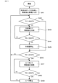
- FIG. 7 is an operation flow diagram of temperature control of the hydrocarbon production system in embodiment 1;
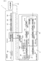
- FIG. 8 is a block diagram showing a hydrocarbon production system according to a second embodiment;
- FIG. 9 is a block diagram showing a hydrocarbon production system according to a third embodiment;
- FIG. 10 is an explanatory diagram showing a heat balance in a hydrocarbon production system according to a third embodiment;
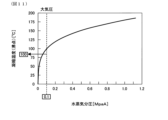
- FIG. 11 is a graph showing a relationship between water vapor partial pressure and water condensation temperature in the third embodiment;
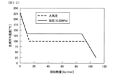
- FIG. 12 is a graph showing the relationship between the amount of recovered heat and the temperature of the generated gas in the third embodiment;
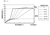
- FIG. 13 is a graph showing a relationship between a heat exchange area and a condensation heat recovery amount for each water vapor pressure difference in the third embodiment;
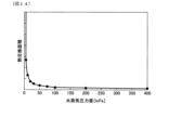
- FIG. 14 is a graph showing the relationship between the water vapor pressure difference and the heat exchange area required to recover all the heat of condensation;
- FIG. 15 is an operation flow diagram showing hydrogen production control of the hydrocarbon production system in the third embodiment;
- FIG. 16 is an operation flow diagram of hydrocarbon production in the hydrocarbon production system in embodiment 3;
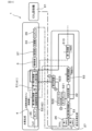
- FIG. 17 is a block diagram showing a hydrocarbon production system in embodiment 4;
- FIG. 18 is a block diagram showing a hydrocarbon production system in the fifth embodiment.
- this embodiment of the hydrocarbon production system 1 includes a hydrocarbon production device 2, an electrolysis device 3, a water vapor supply line 4, and a heat exchanger 51.
- the hydrocarbon generator 2 generates hydrocarbons and water vapor through an exothermic reaction between carbon dioxide gas and hydrogen.
- the hydrocarbon generation reaction in the hydrocarbon generator 2 is usually carried out at 200 to 500°C, and a product gas at 200 to 500°C is generated.
- the carbon oxide gas is, for example, carbon monoxide or carbon dioxide. From the viewpoint of being easily available from combustion furnaces in factories, the atmosphere, etc., the carbon oxide gas is preferably carbon dioxide, and from the viewpoint of high reactivity in producing hydrocarbons, the carbon oxide gas is preferably carbon monoxide. As the carbon oxide gas, carbon dioxide and carbon monoxide may be used in combination. As the hydrocarbon, for example, a saturated hydrocarbon such as methane or ethane is used. When the hydrocarbon is methane, the hydrocarbon production reaction is called methanation. The carbon number of the hydrocarbon can be controlled by changing the catalyst. From the viewpoint of being usable as town gas and being able to be directly synthesized from carbon dioxide and hydrogen by the Sabatier reaction shown in formula (I) described later, the hydrocarbon is preferably methane.
- the hydrocarbon production reaction is an exothermic reaction.
- the chemical reaction formula is represented by the following formula (I).
- ⁇ H represents the enthalpy change before and after the reaction.
- the hydrocarbon production device 2 specifically includes a production reactor 22 (hereinafter, appropriately referred to as the reactor 22) in which a hydrocarbon production reaction takes place, and mass flow controllers 26, 27 for controlling the amount of gas supplied to the reactor 22.
- the first mass flow controller 26 controls the amount of carbon oxide gas such as CO2 supplied.
- the second mass flow controller 27 controls the amount of hydrogen supplied.
- the hydrocarbon production system 1 may further include a CO2 capture device 61.
- the CO2 capture device 61 captures and stores carbon dioxide used as carbon oxide gas from the atmosphere, a combustion furnace, or the like. Carbon dioxide can also be supplied to the electrolysis device 3 and used to generate carbon monoxide.
- the electrolysis device 3 generates hydrogen to be supplied to the hydrocarbon production device 2 from the raw steam.
- the electrolysis device 3 is, for example, composed of an electrolysis reactor and a cell stack housed in the electrolysis reactor, although the configuration is not shown in the figures.
- the cell stack is composed of a plurality of solid oxide electrolysis cells (i.e., SOECs). Although the specific configuration of the electrolysis device 3 is not shown in the figures, a configuration used in the electrolysis of steam using SOECs or the co-electrolysis of steam and carbon dioxide described below can be adopted.
- a water electrolysis reaction occurs in the cell stack as shown in the following formula (II), and hydrogen is generated.
- the electrolysis device 3 it is also possible to generate carbon monoxide together with hydrogen by co-electrolysis of water vapor and carbon dioxide as shown in the following formula (III).
- CO 2 recovered by the CO 2 recovery device 61 is supplied to the electrolysis device 3, and CO 2 is electrolyzed in the electrolysis device 3 together with water vapor supplied from the water vapor supply line 4 to generate carbon monoxide together with hydrogen.
- carbon monoxide is supplied to the production reactor 22 of the hydrocarbon production device 2 together with hydrogen, and methane can be generated by reacting carbon monoxide and hydrogen in the production reactor 22 as shown in the following formula (IV).
- the water vapor supply line 4 evaporates the raw water liquid to generate raw water vapor as shown in formula (VI) and supplies the raw water vapor to the electrolysis device 3.
- the raw water liquid is sent to the electrolysis device side by, for example, a pump 45.
- An evaporator 41 is provided inside the water vapor supply line 4, and supplies thermal energy to the raw water liquid to evaporate the raw water liquid to generate raw water vapor.
- the pump 45 transports the raw water vapor to the electrolysis device 3.
- the evaporator 41 is configured to exchange heat with a first heat exchanger 51.
- the heat exchanger 51 (specifically, the first heat exchanger 51) utilizes the reaction heat generated in the hydrocarbon production device 2 to evaporate the raw liquid water in the steam supply line 4 through heat exchange.
- the first heat exchanger 51 can recover the reaction heat via heat transfer oil and transfer it to the raw liquid water.
- the first heat exchanger 51 is connected to, for example, an oil heater 522 and an oil pump 521.
- the oil pump 521 is also called a thermal oil pump 521.
- a cooler 523 (specifically, a second cooler 523) can be connected to the first heat exchanger 51 to compensate for insufficient cooling.
- the refrigerant is, for example, water.
- the flow of the thermal oil is represented by a solid line, and the flow direction is counterclockwise. The same applies to the flow of the thermal oil illustrated in the subsequent figures.
- the raw liquid water supplied to the first heat exchanger 51 is entirely vaporized by heat received from the thermal oil. Therefore, regardless of the amount of heat generated in the hydrocarbon production device 2, raw water vapor can be generated from the raw liquid water by heat received in the first heat exchanger 51.
- An example of the water evaporation means is an evaporator of the same configuration as the first evaporator 41 that exchanges heat with the first heat exchanger 51. Since there is no need to add such an evaporator, the configuration of the hydrocarbon production system 1 is simplified and control is also made easier.
- the hydrocarbon production system 1 preferably has a compressor 33 that compresses the hydrogen produced in the electrolysis device 3.
- the compressed hydrogen can be supplied to the hydrocarbon production device 2, improving the reaction efficiency of the hydrocarbon production reaction in the hydrocarbon production device 2.
- the hydrocarbon production system 1 further has a buffer tank 35 (specifically, an H2 tank 35) for storing hydrogen, which is arranged between the hydrocarbon production device 2 and the electrolysis device 3.
- the buffer tank 35 can absorb the difference in the amount of hydrogen transfer caused by the difference in response speed, and the stability of the system is improved. From the viewpoint of further improving this effect, it is preferable to adjust the flow rate of the heat transfer oil to 50 to 150 times the flow rate of the raw liquid water or raw steam.
- T1, T2, and T3 represent the temperature sensors shown in Figure 2.
- the temperature sensors may be, for example, thermometers.
- the flow diagram is an example of controlling the thermal oil temperature in the range of 240 to 260°C, and the temperature is changeable.
- the operation flow is controlled, for example, by a control unit (not shown).
- ⁇ Start-up process> 4 when the hydrocarbon production system 1 starts to operate, the thermal oil pump 521 starts to circulate the thermal oil (S11).
- the oil heater 522 starts to heat the thermal oil (S12), and when the temperature of T2 exceeds 250° C., the oil heater 522 stops heating (S13, S14).
- ⁇ Control of hydrogen generation> As shown in Fig. 5, when hydrogen generation is started, the pump 45 of the water vapor supply line 4 is started (S211). The pump 45 sends out a designated amount of water (specifically, raw liquid water) to the first heat exchanger 51 based on a command value of the amount of hydrogen generation (S221). In the first heat exchanger 51, water is evaporated to generate raw water vapor, which is sent to the electrolysis device 3. In the electrolysis device 3, water is electrolyzed to generate hydrogen (S231). The hydrogen is dehydrated in the post-treatment device 37, compressed and pressurized by the compressor 33, and stored in the H2 tank 35 (see Fig. 2).
- the temperature control of the thermal oil is performed by controlling the cooling steps S41 to S45 and the heating steps S46 to S49 while circulating the thermal oil by the thermal oil pump 521.
- the cooling steps S41 to S45 the T1 temperature determination S42 and the T2 temperature determination S44 (when cooling) are performed.
- the T1 temperature determination S42 the temperature of T1 is determined, and if the temperature of T1 exceeds, for example, 260° C., the second cooler 523 is operated and the thermal oil is cooled by the refrigerant (S43).
- the temperature of T2 is determined, and if the temperature of T2 is less than, for example, 250° C., the second cooler 523 is stopped (S45).
- the temperature of T1 is, for example, 260° C. or less in the T1 temperature determination S42
- the heating step is performed, and if the temperature of T2 is, for example, 250° C. or more in the T2 temperature determination S44, the thermal oil is cooled by the refrigerant of the second cooler 523.
- the heating steps S46 to S49 the T2 temperature determination S46 (when heating) and the T3 temperature determination S48 are performed.
- the temperature of T2 is determined, and if the temperature of T2 is, for example, less than 240°C, the oil heater 522 is operated to heat the thermal oil (S47).
- the T3 temperature determination S48 if the temperature of T3 exceeds, for example, 250°C, the heater 522 is stopped (S49). After the oil heater 522 is stopped, the T1 temperature determination S42 in the cooling step is performed.
- FIG. 10 shows a flow in which the cooling step is performed first, the order of the cooling step and the heating step can be reversed.
- the case where the amount of methane produced in the hydrocarbon production device 2 is 1/4 mole per mole of hydrogen produced in the electrolysis device 3 corresponds to the above case (b), but the above case (c) may also occur, for example, when water evaporation is stopped for some reason. Therefore, it is preferable to install a cooler 523 for cooling the heat transfer oil.
- the heat generation amount is less than the recovery amount, the temperature of the thermal oil gradually decreases, but by heating with the oil heater 522, the temperature of the thermal oil can be kept constant throughout the entire circulation path, and the temperature of the production reactor 22 can be maintained at a predetermined temperature, such as 250°C.
- the hydrocarbon production system 1 of this embodiment has the hydrocarbon production device 2, electrolysis device 3, steam supply line 4, and heat exchanger 51 (specifically, first heat exchanger 51) as described above.
- the first heat exchanger 51 uses the reaction heat generated in the hydrocarbon production device 2 to evaporate the raw liquid water in the steam supply line 4.
- the reaction heat is used to evaporate the raw liquid water via heat transfer oil.
- Thermal oil has a larger heat capacity than gases such as steam. Therefore, the thermal oil has a large heat capacity after heat recovery. For example, when the amount of heat generated in the hydrocarbon generation device 2 is large, the thermal oil can recover sufficient reaction heat, and this reaction heat can be used to evaporate the raw liquid water in the steam supply line 4.
- the thermal oil can store sufficient reaction heat, even if the amount of reaction heat generated in the hydrocarbon production device 2 fluctuates and the amount of heat generated decreases or becomes zero, for example, the heat contained in the thermal oil can be supplied to the raw liquid water in the steam supply line 4 and used to evaporate the raw liquid water. In other words, the hydrocarbon production device 2 is highly robust against fluctuations in the amount of heat generated.
- the hydrocarbon production system 1 has a temperature sensor T2 that senses the temperature of the thermal oil flowing into the oil heater 522.
- the oil heater 522 is preferably installed on the thermal oil circulation path and downstream of the first heat exchanger 51, and is configured to control the amount of heating based on the sensing value of the temperature sensor T2. In this case, the temperature control of the thermal oil becomes easy.
- the oil heater 522 is preferably also used to raise the temperature (i.e., warm air) of the hydrocarbon production device 2 when the hydrocarbon production system is started up. Therefore, when the oil heater 522 is provided, there is no need to provide a separate heating device for startup.
- the hydrocarbon production system 1 is preferably configured to include a cooler 23 (specifically, the second cooler 23) downstream of the first heat exchanger in the flow direction of the thermal oil, and a temperature sensor T1 that senses the temperature of the thermal oil flowing into the cooler 23, and to perform cooling based on the sensing value of the temperature sensor T1.
- a cooler 23 specifically, the second cooler 23
- T1 that senses the temperature of the thermal oil flowing into the cooler 23, and to perform cooling based on the sensing value of the temperature sensor T1.
- the thermal oil is cooled by the cooler 23 based on the sensing value (i.e., temperature) of T1, making it easier to control the temperature of the thermal oil to a desired temperature range.
- the hydrocarbon production system 1 of this embodiment includes two hydrocarbon production devices 21 and 22, which are connected in series. Specifically, the gas flow paths of the hydrocarbon production devices 2 are connected in series.
- the two hydrocarbon production devices 2 each include a hydrocarbon production reactor 22.
- a first production reactor 221 is provided upstream of the gas flow path, and a second production reactor 222 is provided downstream of the first production reactor 221.
- the two hydrocarbon production devices 21 and 22 have the same configuration as each other, and each has the same configuration as in embodiment 1.
- the third cooler 543 cools the production gas discharged from the second production reactor 222 and heat exchanged in the third heat exchanger, and liquefies the water vapor.
- the other configurations are the same as in embodiment 1, and the same effects as in embodiment 1 are achieved.
- the water vapor supply line 4 has, for example, evaporators 41, 42 (specifically, a first evaporator 41 and a second evaporator 42) and a pump 45.
- the evaporators 41, 42 supply thermal energy to the raw liquid water and/or raw water vapor.
- heat exchange is performed by the thermal oil in the first heat exchanger 51
- heat exchange is performed by the generated gas in the second heat exchanger 52.
- the second heat exchanger 52 exchanges heat energy of the product gas containing water vapor discharged from the hydrocarbon production apparatus 2 with the raw liquid water or raw steam in the water vapor supply line 4.
- the heat of the product gas refers to the thermal energy held by the product gas discharged from the production reactor 22 of the hydrocarbon production apparatus 2, and is a different concept from the reaction heat generated in the hydrocarbon production reaction in the production reactor 22.
- a first cooler 513 can be provided downstream of the first heat exchanger 51 in the product gas discharge flow path to further cool the product gas whose heat has been released in the first heat exchanger 51.
- the refrigerant is, for example, water.
- the second heat exchanger 52 recovers the thermal energy of the generated gas (specifically, hydrocarbons such as methane, steam) discharged from the hydrocarbon generation device 2, and transfers the heat to the raw liquid water or raw steam.
- the second heat exchanger 52 preferably uses at least the steam in the generated gas as a heat medium and exchanges the heat of this heat medium steam with the raw liquid water or raw steam.
- the second heat exchanger 52 can use the condensation heat of the steam to evaporate the water in the steam supply line 4.
- the second heat exchanger 52 exchanges the heat of the hydrocarbon, the heat balance in the hydrocarbon generation system 1 is further improved, and the thermal efficiency is further improved.
- reaction heat and latent heat of vaporization are obtained, and the latent heat of vaporization is distributed to the steam of the generated gas, and the reaction heat is distributed to the heat medium oil and/or the generated gas. Therefore, the heat of the generated gas means the latent heat of vaporization and a part of the reaction heat, and the heat of the generated gas can also be said to be the heat held by the generated gas after it is recovered to the heat medium oil of the first heat exchanger 51.
- the steam supply line 4 can be equipped with a first evaporator 41 that utilizes the heat of the produced gas and receives heat from a first heat exchanger 51, and a second evaporator 42 that utilizes the reaction heat of the hydrocarbon production and receives heat from a second heat exchanger 52. Also, instead of the first evaporator 41 and the second evaporator 42, it is also possible to use one evaporator that receives heat from both the first heat exchanger 51 and the second heat exchanger 52.
- the first heat exchanger 51 is disposed downstream of the second heat exchanger 52 in the gas flow path. In this case, stable heat exchange is possible even if the amount of thermal energy recovered in the first heat exchanger 51 fluctuates. This is because the first heat exchanger 51, disposed downstream of the second heat exchanger 52, uses a thermal oil with a large heat capacity, and efficient heat exchange is performed in this first heat exchanger 51.
- the generation of raw steam in the steam supply line 4 usually requires sensible heat to heat the raw liquid water up to 100°C, and latent heat associated with phase transition above 100°C.
- the reaction heat from the hydrocarbon production reaction usually provides about 50-70% of the heat required for water evaporation.
- the condensation temperature of water depends on the partial pressure. As shown in Figure 11, the condensation temperature is 100°C at atmospheric pressure (about 0.1 MPa), but by carrying out the hydrocarbon production reaction at high pressure, the partial pressure of water also increases, making it possible to raise the condensation temperature. This increases the amount of heat that can be recovered from the produced gas, and this recovered heat and the reaction heat from the hydrocarbon production reaction can provide almost all of the thermal energy required to generate raw steam (see Figure 10).
- the water vapor partial pressure P1 of the produced gas in the second heat exchanger 52 is preferably higher than the pressure P2 of the raw steam supplied to the electrolysis device 3.
- the water vapor partial pressure P1 of the produced gas can be increased, for example, by compressing hydrogen and/or carbon dioxide flowing into the hydrocarbon production device 2.
- hydrogen is compressed, for example, by a compressor 33 that compresses hydrogen produced in the electrolysis device 3.
- the water vapor partial pressure P1 can also be increased by providing a CO 2 compressor that compresses carbon dioxide and pressurizing the carbon dioxide supplied to the hydrocarbon production device by this CO 2 compressor.
- the produced gas is pressurized by compressing hydrogen and/or carbon dioxide, and the water vapor partial pressure P1 can be increased. It is preferable to compress and pressurize hydrogen by the compressor 33 arranged downstream of the electrolysis device 3 in the gas flow path. In this case, the water vapor partial pressure P1 of the produced gas can be increased more efficiently than the raw steam P2. This is because the hydrogen produced in the electrolysis device 3 is in a low pressure state.
- the condensation heat which accounts for 70 to 80% of the generated gas's heat content, may not be usable as latent heat of vaporization because the condensation temperature of the water vapor is 100°C, but it can be used as sensible heat.
- the generated gas is pressurized (specifically, when the generated gas pressure is higher than atmospheric pressure)
- the water vapor partial pressure P1 of the generated gas is higher than the pressure P2 of the raw water vapor
- the condensation heat can also be used as latent heat of vaporization. This increases the amount of heat recovered and further improves the heat balance in the hydrocarbon generation system 1.
- the pressure in the hydrocarbon generation device 2 for example in the generation reactor 22, is usually higher, and the reaction rate of hydrocarbon generation also increases.
- the second heat exchanger 52 is configured to evaporate a part or all of the raw liquid water that receives heat in the second heat exchanger 52, and is configured to utilize the condensation heat of the water vapor in the produced gas as the latent heat of evaporation of the raw liquid water.
- a specific configuration for utilizing the condensation heat of water vapor for the raw liquid water includes a compressor for compressing hydrogen and/or carbon dioxide, as described above.
- Equations (VII) through (IX) illustrate the main chemical reactions in hydrocarbon production system 1.
- H2O liquid, 25°C
- H2O gas, 100°C
- ⁇ H 46.3 kJ/mol
- H2O ⁇ H2 +1/ 2O2 VIII
- the condensation heat of the water vapor can also be utilized.
- the condensation heat of the water vapor generated in the methanation reaction depends on the pressure, but is approximately 80 kW in the synthesis of 1 mol/sec of methane.
- the condensation temperature of the water vapor generated by methanation and the evaporation temperature of the water supplied to the electrolysis device 3 are in competition with each other, so no temperature difference occurs.
- A represents the heat exchange area
- U represents the overall heat transfer coefficient
- ⁇ T represents the logarithmic mean temperature difference.
- Q A ⁇ U ⁇ ⁇ T ... (X)
- the condensation heat of the water vapor generated by methanation can be used to preheat the water supplied to the electrolysis device 3 up to its boiling point, but it cannot be used as evaporation heat.
- the amount of heat that can be recovered is about 20% of the total condensation heat.
- the condensation temperature of the water vapor contained in the product gas from methanation becomes higher than the evaporation temperature of the water supplied to the electrolysis device 3. Therefore, the condensation heat of the water vapor contained in the product gas from methanation can be recovered as the evaporation heat of the water supplied to the electrolysis device 3.
- Figure 13 shows the relationship between the heat exchange area of the second heat exchanger and the amount of condensation heat recovered.
- the vertical axis of Figure 13 shows the amount of heat that can be recovered from water vapor when methane is synthesized at 1 mol/sec. Note that the plots for 80 kW or more in Figure 13 represent the amount of heat recovered from liquid water after condensation.
- Figure 14 shows the relationship between the pressure difference of the water vapor and the heat exchange area required to recover all the condensation heat.
- the pressure difference is 50 kPa or more
- the reduction in the required heat exchange area is small even if the pressure is increased.
- a specific configuration for using a part of the heat of the generated gas to heat the carbon oxides and hydrogen is a heat exchanger (specifically, a third heat exchanger 53) as shown in FIG. 9.
- the third heat exchanger 53 recovers a part of the heat of the generated gas and causes the carbon oxides and hydrogen to receive the recovered heat. Note that in the drawings, for convenience of illustration, two third heat exchangers are shown, but in reality, they represent one heat exchanger. The other configurations are the same as in embodiment 1, and the same effects as in embodiment 1 are achieved.
- the operation of the hydrocarbon production system 1 of this embodiment will be explained using the operation flow diagrams shown in Figures 4, 7, 15, and 16.
- the flow diagrams are examples of controlling the thermal oil temperature in the range of 240 to 260°C, and the temperature is changeable.
- the operation flow is controlled, for example, by a control unit (not shown).
- the start-up process is, for example, similar to that of the first embodiment (see FIG. 4).
- the temperature control of the thermal oil is, for example, similar to that in the first embodiment (see FIG. 7).
- the first heat exchanger 51 transfers heat from the heat transfer oil to the raw liquid water in the steam supply line 4. Furthermore, the second heat exchanger 52 exchanges heat from the produced gas with the raw liquid water or raw steam in the steam supply line 4, so that the raw steam can receive heat, for example. This improves the thermal efficiency of the hydrocarbon production system 1.
- the hydrocarbon production system 1 of this embodiment includes two hydrocarbon production apparatuses 2, which are connected in series in the same manner as in embodiment 2.
- the other configurations are the same as in embodiment 3.
- the second heat exchanger 52 can exchange heat of the generated gas discharged from each hydrocarbon generation device 2 with the raw liquid water or raw steam in the steam supply line 4.
- the second heat exchanger 52 exchanges heat of the generated gas discharged from the most upstream hydrocarbon generation device 2 (specifically, the first generation reactor 221) with the raw liquid water or raw steam in the steam supply line 4.
- the thermal efficiency of the hydrocarbon generation system 1 is further improved. This is because the first generation reactor 221 has the highest reaction rate and contains the most water vapor in the generated gas.
- the other configurations are the same as those of embodiment 3, and the same effects as those of embodiment 3 are achieved.
- the carbon dioxide circulation system 7 includes a hydrocarbon production system 1, a combustion furnace 71, a carbon dioxide supply line 72, and a hydrocarbon supply line 73.
- the hydrocarbon production system 1 can have a configuration similar to that of the first embodiment, for example, but can also have a configuration similar to that of the second to fourth embodiments.
- the combustion furnace 71 is a facility that uses, for example, hydrocarbons as fuel and generates carbon dioxide through combustion.
- Examples of the combustion furnace 71 include incinerators found in factories and various melting furnaces such as aluminum melting furnaces. Carbon dioxide is emitted from the combustion furnace 71.
- the carbon dioxide supply line 72 supplies the carbon dioxide discharged from the combustion furnace 71 to the hydrocarbon production device 2 of the hydrocarbon production system 1.
- the carbon dioxide is used as carbon oxide gas, and hydrocarbons are produced by a hydrocarbon production reaction.
- the hydrocarbon supply line 73 supplies the hydrocarbons produced by the hydrocarbon production device 2 to the combustion furnace 71. Then, in the combustion furnace 71, as described above, combustion is carried out using the hydrocarbons as fuel. In this way, in the carbon dioxide circulation system 7, carbon dioxide circulates between the hydrocarbon production system 1 and the combustion furnace 71. This makes it possible to build a so-called carbon-neutral system in which greenhouse gas emissions are suppressed.
- the carbon dioxide circulation system 7 is configured to adjust the amount of hydrocarbons produced in the hydrocarbon production device 2 according to the operating state of the combustion furnace 71.
- the adjustment of the amount of hydrocarbons produced is performed, for example, by a control unit (not shown).
- the hydrocarbon production system 1 can produce the required amount of hydrocarbons according to the variation and supply it to the combustion furnace.
- the supply amount is adjusted, for example, by adjusting the amount of hydrogen produced and the amount of hydrocarbons in the hydrocarbon production system 1.
- the hydrogen supplied to the hydrocarbon production device 2 is supplied from the electrolysis device 3.
- the amount of heat used to evaporate water in the water vapor supply line 4 is greater on average than the heat of reaction generated in the hydrocarbon production, so a thermal energy supply is necessary, but since this embodiment has the first heat exchanger 51, additional thermal energy can be supplied from the thermal oil.
- a hydrocarbon production device (2, 21, 22) for producing hydrocarbons by an exothermic reaction between carbon dioxide gas and hydrogen; an electrolysis device (3) for generating hydrogen from raw steam to be supplied to the hydrocarbon generation device; a steam supply line (4) for evaporating the raw material liquid water to generate the raw material steam and supplying the raw material steam to the electrolysis device; a heat exchanger (51) that utilizes reaction heat generated in the hydrocarbon production apparatus for evaporating the raw material liquid water in the steam supply line via a heat transfer oil;
- a hydrocarbon production system (1) comprising: [2] The hydrocarbon production system according to [1], wherein no water evaporation means is provided between the heat exchanger and the electrolysis device in the water vapor supply line.
- the apparatus includes a heater for heating the thermal oil and a temperature sensor for sensing the temperature of the thermal oil flowing into the heater;
- the heater is installed on the circulation path of the thermal oil and downstream of the heat exchanger, and is configured to control the amount of heating based on the sensing value of the temperature sensor.
- the heat exchanger is a first heat exchanger
- a water vapor partial pressure P1 of the produced gas in the second heat exchanger is higher than a pressure P2 of the raw water vapor supplied to the electrolysis device.
- the hydrocarbon production system according to any one of [1] to [6] further comprising a buffer tank (35) for storing hydrogen, disposed between the hydrocarbon production device and the electrolysis device.
- a hydrocarbon production system (1) according to any one of [1] to [7], A combustion furnace (71) that uses a hydrocarbon as fuel and emits carbon dioxide; a carbon dioxide supply line (72) for supplying the carbon dioxide discharged from the combustion furnace as the carbon oxide gas to the hydrocarbon production device of the hydrocarbon production system; a hydrocarbon supply line (73) for supplying the hydrocarbons produced from the hydrocarbon production device to the combustion furnace; A carbon dioxide circulation system (7) configured to adjust the amount of hydrocarbon production in the hydrocarbon production device according to the operating state of the combustion furnace.
Landscapes
- Chemical & Material Sciences (AREA)
- Organic Chemistry (AREA)
- Chemical Kinetics & Catalysis (AREA)
- Engineering & Computer Science (AREA)
- Electrochemistry (AREA)
- Metallurgy (AREA)
- Materials Engineering (AREA)
- Inorganic Chemistry (AREA)
- Oil, Petroleum & Natural Gas (AREA)
- General Chemical & Material Sciences (AREA)
- Automation & Control Theory (AREA)
- Organic Low-Molecular-Weight Compounds And Preparation Thereof (AREA)
- Electrolytic Production Of Non-Metals, Compounds, Apparatuses Therefor (AREA)
Priority Applications (2)
| Application Number | Priority Date | Filing Date | Title |
|---|---|---|---|
| EP23874877.6A EP4600236A4 (en) | 2022-10-05 | 2023-10-03 | HYDROCARBON GENERATION SYSTEM AND CARBON DIOXIDE CIRCULATION SYSTEM |
| US19/171,552 US20250230108A1 (en) | 2022-10-05 | 2025-04-07 | Hydrocarbon generation system and carbon dioxide circulation system |
Applications Claiming Priority (2)
| Application Number | Priority Date | Filing Date | Title |
|---|---|---|---|
| JP2022-161211 | 2022-10-05 | ||
| JP2022161211A JP7750200B2 (ja) | 2022-10-05 | 2022-10-05 | 炭化水素生成システム及び二酸化炭素循環システム |
Related Child Applications (1)
| Application Number | Title | Priority Date | Filing Date |
|---|---|---|---|
| US19/171,552 Continuation US20250230108A1 (en) | 2022-10-05 | 2025-04-07 | Hydrocarbon generation system and carbon dioxide circulation system |
Publications (1)
| Publication Number | Publication Date |
|---|---|
| WO2024075750A1 true WO2024075750A1 (ja) | 2024-04-11 |
Family
ID=90608152
Family Applications (1)
| Application Number | Title | Priority Date | Filing Date |
|---|---|---|---|
| PCT/JP2023/036113 Ceased WO2024075750A1 (ja) | 2022-10-05 | 2023-10-03 | 炭化水素生成システム及び二酸化炭素循環システム |
Country Status (4)
| Country | Link |
|---|---|
| US (1) | US20250230108A1 (cg-RX-API-DMAC7.html) |
| EP (1) | EP4600236A4 (cg-RX-API-DMAC7.html) |
| JP (1) | JP7750200B2 (cg-RX-API-DMAC7.html) |
| WO (1) | WO2024075750A1 (cg-RX-API-DMAC7.html) |
Cited By (1)
| Publication number | Priority date | Publication date | Assignee | Title |
|---|---|---|---|---|
| WO2026150012A1 (fr) * | 2025-01-09 | 2026-07-16 | Genvia | Installation de production d'hydrocarbures |
Families Citing this family (3)
| Publication number | Priority date | Publication date | Assignee | Title |
|---|---|---|---|---|
| JP7895545B1 (ja) * | 2025-03-14 | 2026-07-27 | 三菱電機株式会社 | 電解システム |
| JP2026089667A (ja) * | 2025-10-27 | 2026-06-01 | 東京瓦斯株式会社 | 合成化合物製造システム |
| JP7881031B1 (ja) * | 2025-12-16 | 2026-06-26 | 東京瓦斯株式会社 | 合成化合物製造システム |
Citations (4)
| Publication number | Priority date | Publication date | Assignee | Title |
|---|---|---|---|---|
| US20150080483A1 (en) * | 2012-04-10 | 2015-03-19 | Siemens Aktiengesellschaft | Power station-based methanation system |
| JP2015513531A (ja) * | 2012-02-20 | 2015-05-14 | サーモガス ダイナミクス リミテッドThermogas Dynamics Limited | エネルギー変換および生成のための方法およびシステム |
| JP2020093216A (ja) * | 2018-12-12 | 2020-06-18 | 株式会社Ihi | 触媒反応装置 |
| JP2022161211A (ja) | 2021-04-08 | 2022-10-21 | 株式会社吉野工業所 | 減圧吸収ボトル |
Family Cites Families (1)
| Publication number | Priority date | Publication date | Assignee | Title |
|---|---|---|---|---|
| CN112832963A (zh) * | 2019-11-22 | 2021-05-25 | 张建城 | 太阳能风能与燃气互补联合制氢制甲烷循环热发电装置 |
-
2022
- 2022-10-05 JP JP2022161211A patent/JP7750200B2/ja active Active
-
2023
- 2023-10-03 WO PCT/JP2023/036113 patent/WO2024075750A1/ja not_active Ceased
- 2023-10-03 EP EP23874877.6A patent/EP4600236A4/en active Pending
-
2025
- 2025-04-07 US US19/171,552 patent/US20250230108A1/en active Pending
Patent Citations (4)
| Publication number | Priority date | Publication date | Assignee | Title |
|---|---|---|---|---|
| JP2015513531A (ja) * | 2012-02-20 | 2015-05-14 | サーモガス ダイナミクス リミテッドThermogas Dynamics Limited | エネルギー変換および生成のための方法およびシステム |
| US20150080483A1 (en) * | 2012-04-10 | 2015-03-19 | Siemens Aktiengesellschaft | Power station-based methanation system |
| JP2020093216A (ja) * | 2018-12-12 | 2020-06-18 | 株式会社Ihi | 触媒反応装置 |
| JP2022161211A (ja) | 2021-04-08 | 2022-10-21 | 株式会社吉野工業所 | 減圧吸収ボトル |
Non-Patent Citations (1)
| Title |
|---|
| See also references of EP4600236A4 |
Cited By (1)
| Publication number | Priority date | Publication date | Assignee | Title |
|---|---|---|---|---|
| WO2026150012A1 (fr) * | 2025-01-09 | 2026-07-16 | Genvia | Installation de production d'hydrocarbures |
Also Published As
| Publication number | Publication date |
|---|---|
| JP2024054767A (ja) | 2024-04-17 |
| EP4600236A4 (en) | 2026-01-28 |
| JP7750200B2 (ja) | 2025-10-07 |
| US20250230108A1 (en) | 2025-07-17 |
| EP4600236A1 (en) | 2025-08-13 |
Similar Documents
| Publication | Publication Date | Title |
|---|---|---|
| JP7750200B2 (ja) | 炭化水素生成システム及び二酸化炭素循環システム | |
| US12497919B2 (en) | Raw material fluid treatment plant and raw material fluid treatment method | |
| US6869707B2 (en) | Integrated fuel cell system | |
| US7087652B2 (en) | Process for the production of hydrocarbons | |
| JP5085847B2 (ja) | 出力発生用の膨張機を備える高効率燃料電池発電システム | |
| JP7816062B2 (ja) | 炭化水素生成システム | |
| US20190135624A1 (en) | Installation and method for carbon recovery and storage, without the use of gas compression | |
| JPS6351352B2 (cg-RX-API-DMAC7.html) | ||
| CN116368264A (zh) | 集成式气体发生器和电力储存系统 | |
| JP6813505B2 (ja) | 二水素を製造するためのシステム及び関連する方法 | |
| JP7713864B2 (ja) | ガスタービンシステム | |
| JP2024054767A5 (cg-RX-API-DMAC7.html) | ||
| JPS60235718A (ja) | アンモニア製造方法及びプラント | |
| JP2004018343A (ja) | 炭化水素燃料からの電力と水素の併産方法とそのプラント及びその排熱回収型改質器 | |
| JP6964920B1 (ja) | 発電設備併設気化利用炭化水素製造システム | |
| KR102334163B1 (ko) | 메탄 생성 장치 및 이의 제어 방법 | |
| JP2006046132A (ja) | ガスタービンシステムと改質燃料焚きガスタービンシステム及びガスタービンシステムの改質燃料供給方法 | |
| JP4496327B2 (ja) | 化学エネルギーを用いる熱回収と熱利用および発電の方法 | |
| WO2025056232A1 (en) | Production of a hydrogen-containing synthesis gas by conversion of a hydrocarbon feedstock | |
| JPH0377121B2 (cg-RX-API-DMAC7.html) | ||
| JP2026067257A (ja) | 燃料製造システム及び燃料製造方法 | |
| US20230382725A1 (en) | Benzene battery cycle | |
| US20250041757A1 (en) | Process for producing methanol with utilization of the waste heat from an electrolyser | |
| WO2026033985A1 (ja) | 水素製造システム | |
| CN121772970A (zh) | 生成装置 |
Legal Events
| Date | Code | Title | Description |
|---|---|---|---|
| 121 | Ep: the epo has been informed by wipo that ep was designated in this application |
Ref document number: 23874877 Country of ref document: EP Kind code of ref document: A1 |
|
| NENP | Non-entry into the national phase |
Ref country code: DE |
|
| WWE | Wipo information: entry into national phase |
Ref document number: 2023874877 Country of ref document: EP |
|
| ENP | Entry into the national phase |
Ref document number: 2023874877 Country of ref document: EP Effective date: 20250506 |
|
| WWP | Wipo information: published in national office |
Ref document number: 2023874877 Country of ref document: EP |