WO2024075628A1 - 電力伝送システム - Google Patents
電力伝送システム Download PDFInfo
- Publication number
- WO2024075628A1 WO2024075628A1 PCT/JP2023/035396 JP2023035396W WO2024075628A1 WO 2024075628 A1 WO2024075628 A1 WO 2024075628A1 JP 2023035396 W JP2023035396 W JP 2023035396W WO 2024075628 A1 WO2024075628 A1 WO 2024075628A1
- Authority
- WO
- WIPO (PCT)
- Prior art keywords
- power
- unit
- power transmission
- detection
- secondary battery
- Prior art date
- Legal status (The legal status is an assumption and is not a legal conclusion. Google has not performed a legal analysis and makes no representation as to the accuracy of the status listed.)
- Ceased
Links
Images


Classifications
-
- H—ELECTRICITY
- H02—GENERATION; CONVERSION OR DISTRIBUTION OF ELECTRIC POWER
- H02J—ELECTRIC POWER NETWORKS; CIRCUIT ARRANGEMENTS OR SYSTEMS FOR SUPPLYING OR DISTRIBUTING ELECTRIC POWER; SYSTEMS FOR STORING ELECTRIC ENERGY
- H02J50/00—Circuit arrangements or systems for wireless supply or distribution of electric power
- H02J50/20—Circuit arrangements or systems for wireless supply or distribution of electric power using microwaves or radio frequency waves
-
- H—ELECTRICITY
- H02—GENERATION; CONVERSION OR DISTRIBUTION OF ELECTRIC POWER
- H02J—ELECTRIC POWER NETWORKS; CIRCUIT ARRANGEMENTS OR SYSTEMS FOR SUPPLYING OR DISTRIBUTING ELECTRIC POWER; SYSTEMS FOR STORING ELECTRIC ENERGY
- H02J50/00—Circuit arrangements or systems for wireless supply or distribution of electric power
- H02J50/80—Circuit arrangements or systems for wireless supply or distribution of electric power involving the exchange of data, concerning supply or distribution of electric power, between transmitting devices and receiving devices
-
- H—ELECTRICITY
- H02—GENERATION; CONVERSION OR DISTRIBUTION OF ELECTRIC POWER
- H02J—ELECTRIC POWER NETWORKS; CIRCUIT ARRANGEMENTS OR SYSTEMS FOR SUPPLYING OR DISTRIBUTING ELECTRIC POWER; SYSTEMS FOR STORING ELECTRIC ENERGY
- H02J7/00—Circuit arrangements for charging or discharging batteries or for supplying loads from batteries
-
- H—ELECTRICITY
- H02—GENERATION; CONVERSION OR DISTRIBUTION OF ELECTRIC POWER
- H02J—ELECTRIC POWER NETWORKS; CIRCUIT ARRANGEMENTS OR SYSTEMS FOR SUPPLYING OR DISTRIBUTING ELECTRIC POWER; SYSTEMS FOR STORING ELECTRIC ENERGY
- H02J7/00—Circuit arrangements for charging or discharging batteries or for supplying loads from batteries
- H02J7/34—Parallel operation in networks using both storage and other DC sources, e.g. providing buffering
-
- H—ELECTRICITY
- H04—ELECTRIC COMMUNICATION TECHNIQUE
- H04B—TRANSMISSION
- H04B5/00—Near-field transmission systems, e.g. inductive or capacitive transmission systems
- H04B5/40—Near-field transmission systems, e.g. inductive or capacitive transmission systems characterised by components specially adapted for near-field transmission
- H04B5/48—Transceivers
Definitions
- the present invention relates to a power transmission system.
- a contactless charging system is known as a power transmission system (see Patent Document 1).
- the contactless power supply system disclosed in Patent Document 1 includes a power transmitting device having a power transmitting unit and a communication means, and a power receiving device having a power receiving unit, a communication means, and a switching means.
- the power transmitting unit transmits minute power to the power receiving unit before charging of a battery (secondary battery) connected to the power receiving device begins. This makes it possible to restore the contactless charging system without requiring mechanical contact between the power transmitting unit and the power receiving unit.
- a communication path with a power source is secured between the power transmitting device and the power receiving device, which is a separate system from the power transmission path of the non-contact power supply.
- the non-contact charging system then acquires information indicating the battery status from the power receiving device and transmits it to the power transmitting device. This allows the power transmitting device to determine whether or not power transmission is required.
- the communication path is a separate system from the power transmission path and has its own power source, which results in excessive costs and power consumption for the communication device.
- the object of the present invention is to solve the above problems and to provide a power transmission system that can reduce the cost of unnecessary communication devices and unnecessary power consumption, and is highly energy-efficient.
- the power transmission system includes a microwave contactless power supply device that supplies power to a secondary battery by propagating microwaves in a contactless manner, the microwave contactless power supply device having a power transmitter that transmits microwaves and a power receiver that receives the microwaves transmitted from the power transmitter, the power receiver including a detection unit that detects the charge state of the secondary battery and a notification unit that notifies the transmitter of the detection result of the detection unit using wireless communication, the detection unit and the notification unit being provided midway along the power transmission path to the secondary battery, and the power transmitter including a judgment unit that judges whether or not to transmit power based on the detection result of the detection unit notified by the notification unit.
- the present invention reduces the cost of unnecessary communication devices and unnecessary power consumption, making the power transmission system highly energy-efficient.
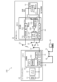
- FIG. 1 is a block diagram showing a power transmission system according to an embodiment of the present invention.
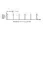
- FIG. 2 is a graph showing waveforms during intermittent readout according to the embodiment of the present invention.
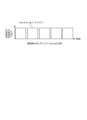
- FIG. 3 is a graph showing waveforms during continuous readout according to the embodiment of the present invention.
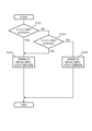
- FIG. 4 is a flowchart showing the transmission power transmission control according to the embodiment of the present invention.
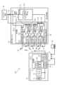
- FIG. 5 is a block diagram showing a power transmission system according to a first modified example of the embodiment of the present invention.
- FIG. 6 is a flowchart showing transmission power transmission control according to the first modification of the embodiment of the present invention.
- FIG. 7 is a flowchart showing control for notifying a user of the timing for replacing a backup power supply according to the first modification of the embodiment of the present invention.
- Fig. 1 is a block diagram showing a power transmission system 100 according to an embodiment of the present invention. As shown in Fig. 1, the power transmission system 100 is a system that performs power transmission by microwave power transmission.
- the power transmission system 100 is applied to a hotel lock system.
- systems to which the power transmission system 100 can be applied are not limited to hotel lock systems.
- Other examples of systems to which the power transmission system 100 can be applied include door lock systems for homes, including apartment complexes, stores, offices, factories, etc.
- the power transmission system 100 includes a card switch system 10 and an electronic lock system 20.
- the card switch system 10 includes a power source 11 and a card switch 12.
- the card switch system 10 supplies power to the card switch 12 and switches the card switch 12 on or off.
- the power source 11 supplies power to the card switch 12 via the power grid.
- the card switch 12 supplies power from the power source 11 to the compartment when a contactless IC card used to unlock or lock the door is inserted into the partition wall adjacent to the door that forms the entrance to the compartment. When the contactless IC card is removed, the card switch 12 cuts off the supply of power from the power source 11 to the compartment.
- the card switch 12 is connected to the power source 11 by a power line.
- the electronic lock system 20 includes an electronic lock 21 installed on the door.
- the electronic lock system 20 is a system that unlocks or locks the door using power supplied to the electronic lock 21 installed on the door.
- the compartment having an entrance that is unlocked or locked by a door is a hotel guest room
- the interior of the compartment is the interior of the guest room
- the exterior of the compartment is the hotel corridor space
- the structure having multiple compartments is a hotel building
- the electronic lock 21 is a hotel lock.
- the electronic lock 21 is called a keyless lock, and as the name suggests, it is a lock that does not require a key.
- the electronic lock 21 is a lock that incorporates a mechanism that uses electrical power to lock and unlock the door.
- the electronic lock 21 is different from an electric lock that is powered using electrical wiring.
- the electronic lock 21 does not require electrical wiring that runs through a power grid from a power source.
- the electronic lock 21 is not a typical lock that uses a battery, but rather a lock that locks and unlocks the door using power supplied by microwave power transmission.
- the electronic lock 21 has a secondary battery 211 connected to the GND terminal.
- the electronic lock 21 locks and unlocks the door using the power of the charged secondary battery 211.
- the secondary battery 211 is charged with power from a power source transmitted by microwave power transmission.
- the microwave contactless power supply device 1 is arranged separately between a door where an electronic lock 21 is provided and a partition where the door is also provided.
- the microwave contactless power supply device 1 transmits microwaves in a contactless state from the partition side to the door side to supply power to a secondary battery 211 of the electronic lock 21.
- the microwave contactless power supply device 1 has a power transmitter 13 and a power receiver 22.
- the power transmitter 13 is a microwave power transmission transmitter.
- the power transmitter 13 has an MCU (Micro Controller Unit) 14, a reader/writer unit 16, a first wireless communication antenna 17, a WLAN (Wireless LAN) 18, and a second wireless communication antenna 19.
- the MCU 14 includes a CPU, a communication port, and a control unit 142, and controls the power transmission of the power transmitter 13.
- the WLAN 18 enables the power transmitter 13 to wirelessly communicate with an external system 30 mounted on a notebook PC or the like.
- the power transmitter 13 transmits microwaves supplied from the power source 11 to the power receiver 22.
- the power transmitter 13 is mounted on the card switch system 10.
- the power transmitter 13 is installed in a partition wall adjacent to the door that forms an entrance/exit within the compartment.
- the power transmitter 13 is disposed in a power transmission network from the power source 11 to the card switch 12.
- the power transmitter 13 is electrically connected to the power source 11 using a power transmission line without passing through the card switch 12 so that the card switch 12 does not switch on or off the electricity in the power transmission network from the power source 11 to the card switch 12.
- the power transmitter 13 transmits microwave power from the reader/writer unit 16 to the first wireless communication antenna 17 via a power transmission and communication line.
- the power transmitter 13 transmits microwave wireless power to the power receiver 22 using the first wireless communication antenna 17 without using a wire such as a power transmission line.
- the power transmitter 13 connects the reader/writer unit 16 and the first wireless communication antenna 17 via a power transmission and communication line.
- the power transmitter 13 can communicate with the external system 30 using the WLAN 18.
- the power transmitter 13 connects the WLAN 18 to a second wireless communication antenna 19 via a communication line.
- the second wireless communication antenna 19 is connected to an external wireless antenna 31 of the external system 30 via a wireless line, allowing wireless communication between the power transmitter 13 and the external system 30.
- the power receiver 22 is a microwave power transmission receiver that receives microwaves from the power transmitter in a non-contact state.
- the power receiver 22 supplies the power received from the power transmitter 13 in a non-contact state to a secondary battery 211 of the electronic lock 21.
- the power receiver 22 uses power supply by microwave power transmission instead of a battery.
- the electronic lock 21 is equipped with an NFC card reader, a deadbolt, a motor for driving a latch bolt, etc. For this reason, in the case of a battery-powered electronic lock, it is a product that can only operate on a battery for about one year, and the battery needs to be replaced once a year. In contrast, the electronic lock 21 is equipped with a secondary battery 211, and does not require battery replacement or maintenance.
- the receiver 22 is incorporated in an electronic lock 21 that locks and unlocks the door, and is built into the electronic lock 21 that is attached to the door handle that the user uses to open and close the door.
- the receiver 22 is mounted in the electronic lock system 20 together with the electronic lock 21.
- the receiver 22 has a receiving antenna 23, a rectifier circuit 221, a capacitor (capacity) 222 connected to the ground terminal GND, an RFID tag section A26, and a third wireless communication antenna 27.
- the receiver 22 receives the microwaves transmitted from the first wireless communication antenna 17 of the transmitter 13 via the receiving antenna 23.
- the receiver 22 charges the capacitor 222 connected to the ground terminal GND through the receiving antenna 23 and rectifier circuit 221 connected via a power transmission line with the power transmitted from the transmitter 13, and uses the power as the power source for the electronic lock 21.
- the receiver 22 can wirelessly communicate with the reader/writer unit 16 of the transmitter 13 using the RFID tag unit A26.
- the receiver 22 connects the RFID tag unit A26 to the third wireless communication antenna 27 via a communication line.
- the electronic lock 21 can exchange information with the external system 30 and can be controlled from the external system 30 via wireless communication between the RFID tag unit A26 and the reader/writer unit 16 using the first wireless communication antenna 17 and the third wireless communication antenna 27.
- the UHF band is used as the wireless communication method between the RFID tag unit A26 and the reader/writer unit 16.
- backscatter communication is used as the wireless communication method between the RFID tag unit A26 and the reader/writer unit 16.
- Backscatter communication is a communication method used by the passive tag of the RFID tag unit A26 of the RFID.
- the passive tag of the RFID tag unit A26 operates by converting the transmission power of the reader/writer unit 16 to DC and using it as power supply.
- a response to the reader/writer unit 16 is generated by modulating the transmission wave (UHF RFID Tag read command) of the reader/writer unit 16 by changing the internal impedance.
- UHF RFID Tag read command UHF RFID Tag read command
- the microwave contactless power supply device 1 transmits power by microwave power transmission.
- Microwave power transmission enables a relatively long transmission distance. Although increasing the transmission distance inevitably increases propagation loss, which limits the improvement of power efficiency, it also has the advantage of increasing the degree of freedom in the distance between the power transmitting and receiving devices.
- the distance between the transmitter 13 and receiver 22 capable of transmitting 2.0 mW of operating power consumption of the electronic lock 21 is approximately 37 cm, as calculated by the above formula (1).
- the card switch 12 installed on the partition (wall) is installed at a relatively short distance from the electronic lock 21.
- the power supply within the partition is cut off and the interior lights are turned off.
- the card switch 12 is necessarily installed near the doorknob.
- the power supply 11 for this card switch 12 is equipped with a power transmitter 13 that is powered by the power supply 11 regardless of whether the card switch 12 is locked or unlocked. This makes it possible to constantly supply power via microwave power transmission.
- the microwave contactless power supply device 1 is made up of a power transmitter 13 incorporated in the card switch system 10 and a power receiver 22 incorporated in the electronic lock system 20.
- the power transmitter 13 is provided inside a partition in a compartment having an entrance that is opened and closed by a door, and the power receiver 22 is built into an electronic lock 21 provided in the door handle of the door. Even if the compartment and the electronic lock 21 are separated by a certain distance, the electronic lock 21 is supplied with power by microwave power transmission. This makes it possible to realize a stable power supply to the electronic lock 21 by taking advantage of the freedom of positioning the power transmitter 13 and the power receiver 22 that constitute the microwave contactless power supply device 1 at a desired distance.
- the receiver 22 also has an RFID tag section A (UHF band RFID tag) 26, which is connected to the electronic lock 21 and provides an interface, allowing communication between the card switch system 10 and the electronic lock system 20.
- RFID tag section A UHF band RFID tag
- the power receiver 22 includes a detection unit and a notification unit.
- the detection unit and the notification unit are provided in the power receiver 22 at a portion of the power transmission path of the power transmission line before the power transmission path reaches the secondary battery 211, and branch off from the portion.
- the detection unit detects the charge state of the secondary battery 211.
- the detection unit includes voltage dividing resistors 223 and 224, a comparator 226, and a switching element 227.
- the voltage dividing resistors 223 and 224 form a voltage dividing circuit that divides the output voltage of the secondary battery 211.
- the voltage dividing resistors 223 and 224 are arranged between the secondary battery 211 and the ground terminal GND.
- the voltage dividing resistors 223 and 224 divide the output voltage of the secondary battery 211 based on the resistance ratio (voltage dividing ratio) between the resistance value including the voltage dividing resistor 223 on the secondary battery 211 side and the resistance value including the voltage dividing resistor 224 on the ground terminal GND side.
- the voltage as a physical quantity representing the charge state of the secondary battery 211 is adjusted to a level comparable to the reference value REFB225.
- the divided voltage is input to the comparator 226.
- the comparator 226 compares the divided voltage input to the inverting input terminal with a reference voltage (reference value REFB225) input to the non-inverting input terminal.
- the switching element 227 is connected to the output of the comparator 226 and also to the RFID tag part B228.
- the switching element 227 is ON when the divided voltage is greater than the reference value REFB225, and is OFF when the divided voltage is equal to or less than the reference value REFB225.
- the divided voltage is greater than the reference value REFB225, it means that the secondary battery 211 has sufficient stored power.
- the divided voltage is equal to or less than the reference value REFB225, it means that the secondary battery 211 does not have sufficient stored power.
- the notification unit notifies the power transmitter 13 of the detection result of the detection unit by wireless communication.
- the notification unit is the RFID tag unit B228, and notifies the power transmitter 13 of the detection result of the detection unit by wireless communication from the RFID tag unit B228 to the reader/writer unit 16.
- Various methods can be used as the wireless communication method between the RFID tag unit B228 and the reader/writer unit 16, but here, backscatter communication using the UHF band is used, as with the wireless communication method between the RFID tag unit A26 and the reader/writer unit 16.
- the passive tag of the RFID tag unit B228 operates by converting the transmission power of the reader/writer unit 16 to DC and using it as power supply power.
- the response to the reader/writer unit 16 is modulated by changing the internal impedance against the transmission wave (UHF RFID Tag read command) of the reader/writer unit 16, and a response signal is created.
- the RFID tag unit B228 has a memory (not shown) that records whether the switching element 227 is ON or OFF, that is, the state between the terminals of the switching element 227 (hereinafter simply referred to as the "state between the terminals").
- a response signal that can identify whether the state between the terminals is ON or OFF is created in response to the transmission wave (UHF RFID Tag read command) of the reader/writer unit 16.
- the reader/writer unit 16 reads the state between the terminals from the response signal, and the detection result of the detection unit is notified to the power transmitter 13.
- the power transmitter 13 includes a determination unit.
- the determination unit determines whether or not power transmission is possible based on the detection result of the detection unit notified by the notification unit.
- the determination unit stops power transmission based on the detection result that the charge state of the secondary battery 211 at the detection unit exceeds the reference value REFB225.
- the determination unit starts power transmission based on the detection result that the charge state of the secondary battery 211 at the detection unit falls below the reference value REFB225.
- the determination unit is configured in the MCU 14.
- FIG. 2 is a graph showing a waveform during intermittent readout according to an embodiment of the present invention.
- the waveform during intermittent readout which intermittently reads out the state between the terminals of the RFID tag portion B228, is an intermittent waveform in which the period during which the output of the transmission signal and the transmitted power is high is short, and the period between periods during which the output of the transmission signal and the transmitted power is high is long (in other words, the duty ratio is low), and the output is repeated intermittently.
- FIG. 3 is a graph diagram showing a waveform during continuous readout according to an embodiment of the present invention.
- the waveform during continuous readout which continuously reads out the state between the terminals of the RFID tag portion B228, has a long period during which the output of the transmission signal and the transmitted power is high, and the period between periods during which the output of the transmission signal and the transmitted power is high is short (in other words, the duty ratio is high), and is a continuous waveform in which the output is repeated continuously.
- the control unit 142 of the power transmitter 13 controls the output of the power transmission so that when the judgment unit stops power transmission, the output waveform of the power transmission exhibits the intermittent waveform shown in FIG. 2.
- the control unit 142 of the power transmitter 13 also controls the output of the power transmission so that when the judgment unit starts power transmission, the output waveform of the power transmission exhibits the continuous waveform shown in FIG. 3.
- the amplification of the power transmission output is appropriately performed by the control unit 142 while maintaining the timing. In other words, the control unit 142 performs power transmission control to make the output waveform of the power transmission of the power transmitter 13 different between when the judgment unit stops power transmission and when the judgment unit starts power transmission.
- the transmission of UHF RFID Tag read commands from the reader/writer unit 16 to the RFID tag unit A26 and the RFID tag unit B228 also serves to transmit power from the power transmitter 13 to the power receiver 22. Therefore, when the determination unit stops power transmission, the output waveform of the UHF RFID Tag read command becomes intermittent as shown in Figure 2, and the output waveform of the transmitted power also becomes intermittent as shown in Figure 2. Similarly, when the determination unit starts power transmission, the output waveform of the UHF RFID Tag read command becomes continuous as shown in Figure 3, and the output waveform of the transmitted power also becomes intermittent as shown in Figure 3.
- ⁇ Description of the process flow of transmission power transmission control> 4 is a flowchart showing the transmission power transmission control according to the embodiment of the present invention.
- control unit 142 determines whether the switching element 227 is ON. If the switching element 227 is ON (S101-YES), the process proceeds to S102. If the switching element 227 is not ON (S101-NO), the process proceeds to S103.
- control unit 142 transmits the transmission power intermittently. After processing in S102, the processing ends for the time being.
- control unit 142 transmits the power continuously. After the processing of S103, the processing ends for the time being.
- Fig. 5 is a block diagram showing a power transmission system 100 according to the first modification of the embodiment of the present invention.
- the power transmission system 100 includes two detection units and notification units provided in the power receiver 22.
- the two detection units include voltage dividing resistors 223, 224, and 229, comparators 226 and 231, and switching elements 227 and 232.
- Reference values for comparing the charge states of the secondary battery 211 in the two detection units include a stop reference value REFB225 at which the determination unit stops power transmission, and a start reference value REFC230 that is lower than the stop reference value REFB225 and at which the determination unit starts power transmission.
- voltage-dividing resistor 224 is placed between voltage-dividing resistors 223 and 229 and is not directly connected to the ground terminal GND. Rectifying resistor 229 is connected to the ground terminal GND.
- the comparator 226 receives the output voltage between the rectifier resistors 223 and 224.
- the output voltage between the voltage-dividing resistors 223 and 224 is obtained by dividing the voltage as a physical quantity representing the charge state of the secondary battery 211 based on a resistance ratio (first voltage division ratio) between the resistance value including the voltage-dividing resistor 223 on the secondary battery 211 side and the resistance value including the voltage-dividing resistors 224 and 229 on the ground terminal GND side.
- the comparator 226 compares the voltage divided based on the first voltage division ratio with a reference voltage (stop reference value REFB225).
- the comparator 231 receives the output voltage between the voltage-dividing resistors 224 and 229.
- the output voltage between the voltage dividing resistors 224 and 229 is obtained by dividing the voltage as a physical quantity representing the charge state of the secondary battery 211 based on the resistance ratio (second voltage dividing ratio) between the resistance value including the voltage dividing resistors 223 and 224 on the secondary battery 211 side and the resistance value including the voltage dividing resistor 229 on the ground terminal GND side.
- the comparator 231 compares the voltage divided based on the second voltage dividing ratio with a reference voltage (start reference value REFC230).
- the switching element 227 is connected to the output of the comparator 226 and to the RFID tag section B228.
- the switching element 227 is ON when the voltage divided based on the first voltage division ratio is greater than the reference value REFB225, and is OFF when the voltage divided based on the first voltage division ratio is equal to or less than the reference value REFC225.
- the switching element 232 is connected to the output of the comparator 231 and to the RFID tag section C233.
- the switching element 232 is ON when the voltage divided based on the second voltage division ratio is greater than the reference value REFC230, and is OFF when the voltage divided based on the second voltage division ratio is equal to or less than the reference value REFC230.
- the storage state of the secondary battery 211 is at a high level (for example, a fully charged state).
- the storage state of the secondary battery 211 is at a low level.
- the storage state of the secondary battery is at a medium level. For example, when the storage state is at a high level or a medium level, it may be determined that the storage is sufficient, and when the storage state is at a low level, it may be determined that the storage is not sufficient.
- the plurality of detection units may have different reference values for comparing the charge state of the secondary battery.
- ⁇ Description of the process flow of transmission power transmission control> 6 is a flowchart showing a transmission power transmission control according to the first modified example of the embodiment of the present invention.
- control unit 142 determines whether the switching element 227 is ON or not. If the switching element 227 is ON (S101-YES), the process proceeds to S102. The process of S102 is the same as in the embodiment of the present invention. If the switching element 227 is not ON (S101-NO), the process proceeds to S104.
- control unit 142 determines whether the switching element 232 is ON. If the switching element 232 is ON (S104-YES), the process proceeds to S102. If the switching element 232 is not ON (S104-NO), the process proceeds to S103. The process of S103 is the same as in the embodiment of the present invention.
- the power transmission system 100 includes a backup power supply (primary battery) 40.
- the backup power supply 40 is connected to a first power supply line 61 that connects the power receiver 22 and the secondary battery 211 of the electronic lock 21 via a second power supply line 62.
- the backup power supply 40 switches power supply from the power receiver 22 to supply power stored inside to the secondary battery 211 of the electronic lock 21.
- the backup power supply 40 must meet the conditions of low self-discharge and long-term operation. For this reason, for example, a lithium thionyl chloride battery is used for the backup power supply 40.
- a lithium thionyl chloride battery is a battery that meets the above conditions and is used in smart meters, etc.
- the output voltage of a lithium thionyl chloride battery is 3.6 V, which is higher than other primary batteries.
- the power transmission system 100 includes a diode 41.
- the diode 41 is disposed midway along the second power supply line 62, and blocks power supply from the power receiver 22 to the backup power supply 40 while allowing power supply from the backup power supply 40 to the secondary battery 211 of the electronic lock 21.
- the power transmission system 100 includes a remaining amount detection unit and a remaining amount notification unit.
- the remaining amount detection unit and the remaining amount notification unit are configured in the power receiver 22.
- the remaining charge detection unit detects the remaining battery charge of the backup power supply 40.
- the remaining charge detection unit includes voltage dividing resistors 234, 235, a comparator 237, and a switching element 238.
- the voltage dividing resistors 234, 235 form a voltage dividing circuit that divides the output voltage of the backup power supply 40.
- the voltage dividing resistor 235 is connected to the ground terminal GND.
- the comparator 237 receives the output voltage between the voltage dividing resistors 234, 235.
- the output voltage between the voltage dividing resistors 234, 235 is obtained by dividing the voltage as a physical quantity representing the remaining battery charge of the backup power supply 40 based on the resistance ratio (third voltage dividing ratio) between the resistance value including the voltage dividing resistor 234 on the backup power supply 40 side and the voltage dividing resistor 235 on the ground terminal GND side.
- the comparator 237 compares the voltage divided based on the third voltage dividing ratio with a reference voltage (reference value REFD236).
- the switching element 238 is connected to the output of the comparator 237 and is also connected to the RFID tag section D239.
- the switching element 238 is ON when the voltage divided based on the third voltage division ratio is greater than the reference value REFD236, and is OFF when the voltage divided based on the third voltage division ratio is equal to or less than the reference value REFD236.
- the voltage divided based on the third voltage division ratio is greater than the reference value REFD236, it means that the remaining battery charge of the backup power supply 40 is sufficient.
- the voltage divided based on the third voltage division ratio is equal to or less than the reference value REFD236, it means that the remaining battery charge of the backup power supply 40 is not sufficient.
- the remaining amount notification unit notifies the power transmitter 13 of the detection result of the remaining amount detection unit using wireless communication.
- the remaining amount notification unit is an RFID tag unit D239, and notifies the power transmitter 13 of the detection result of the detection unit by wireless communication from the RFID tag unit D239 to the reader/writer unit 16.
- the power transmitter 13 includes a replacement determination unit.
- the replacement determination unit determines whether or not the backup power source 40 should be replaced based on the detection result of the remaining amount detection unit notified by the remaining amount notification unit.
- the replacement determination unit is configured in the MCU 14.
- ⁇ Description of Processing Flow for Controlling Notification of Replacement Time of Backup Power Supply 40> 7 is a flowchart showing replacement time notification control for the backup power supply 40 according to a modified embodiment of the present invention.
- control unit 142 determines whether the switching element 238 is ON. If the switching element 238 is ON (S201-YES), the process ends. If the switching element 238 is not ON (S201-NO), the process proceeds to S202.
- control unit 142 notifies the external system 30 via the WLAN 18 that it is time to replace the backup power supply 40.
- the power transmission system 100 includes a microwave contactless power supply device 1 that supplies power to a secondary battery 211 by propagating microwaves in a contactless state.
- the microwave contactless power supply device 1 includes a power transmitter 13 that transmits microwaves, and a power receiver 22 that receives the microwaves transmitted from the power transmitter 13.
- the power receiver 22 includes a detection unit that detects the charge state of the secondary battery 211, and a notification unit that notifies the power transmitter 13 of the detection result of the detection unit using wireless communication.
- the detection unit and the notification unit are provided midway along the power transmission path to the secondary battery 211.
- the power transmitter 13 includes a determination unit that determines whether or not power transmission is possible based on the detection result of the detection unit notified by the notification unit.
- the determination unit stops power transmission based on the detection result that the charge state of the secondary battery 211 in the detection unit exceeds the reference value REFB225.
- This configuration reduces unnecessary power consumption, making the power transmission system 100 highly energy-efficient.
- the determination unit starts transmitting power based on the detection result that the charge state of the secondary battery 211 in the detection unit falls below the reference value REFB225.
- the power transmitter 13 starts transmitting power when necessary, and the charge state of the secondary battery 211 becomes stable.
- the power transmitter 13 has a reader/writer unit 16.
- the power receiver 22 has an RFID tag unit B228 that can wirelessly communicate with the reader/writer unit 16.
- the power transmitter 13 and the power receiver 22 can wirelessly communicate in different frequency bands during power transmission from the power transmitter 13 to the power receiver 22 via microwave contactless power supply.
- the wireless communication between the reader/writer unit 16 and the RFID tag unit B228 is backscatter communication.
- the power transmitter 13 and the power receiver 22 can wirelessly communicate using backscatter communication in different frequency bands.
- the detection unit includes a comparator 226 that compares the voltage of the secondary battery 211 with a reference value REFB225, and a switching element 227 that is connected to the output of the comparator 226 and is also connected to the RFID tag unit B228.
- the notification unit notifies the power transmitter 13 of the detection result of the detection unit by wireless communication from the RFID tag unit B228 to the reader/writer unit 16.
- the detection results of the detector can be communicated to the power transmitter 13 using wireless communication without the need for a communication means with a separate power source.
- the multiple detection units each have a different reference value REF for comparing the charge state of the secondary battery 211.
- the start and end of power transmission can be set at different physical quantity levels using different reference values REF.
- the reference values for comparing the charge state of the secondary battery 211 in the two detection units include a stop reference value REFB225 at which the determination unit stops power transmission, and a start reference value REFC230 that is lower than the stop reference value REFB225 and at which the determination unit starts power transmission.
- the stop and start of power transmission can be set at different physical quantity levels using a stop reference value REFB225 and a start reference value REFC230 that are different from each other.
- the power transmission system 100 includes a backup power source 40 that switches the power supply from the power receiver 22 to supply power to a secondary battery 211.
- the power transmission system 100 includes a remaining charge detection unit that detects the remaining battery charge of the backup power source 40.
- the power transmission system 100 includes a remaining charge notification unit that notifies the power transmitter 13 of the detection result of the remaining charge detection unit using wireless communication.
- the power transmitter 13 includes an exchange determination unit that determines whether or not the backup power source 40 can be replaced based on the detection result of the remaining charge detection unit notified by the remaining charge notification unit.
- the backup power supply 40 can be monitored without the need for a separate communication means for the power supply, making it possible to detect depletion of the backup power supply 40 and quickly notify the user when it is time to replace the backup power supply 40.
- the power transmitter 13 has a control unit 142 that performs control to make the output waveform of the power transmission different between when the determination unit stops power transmission and when the determination unit starts power transmission.
- microwave power transmission is used to transmit microwaves from the power transmitter 13 to the power receiver 22 in a non-contact state, and the power is supplied to the secondary battery 211 of the electronic lock 21.
- the power received by the power receiver 22 may be supplied to the secondary battery 211 of a different operating device.
- the power transmitter 13 may be installed not only inside the partition but also outside the partition (such as in a hallway space in a hotel). When the power transmitter 13 is installed outside the partition, for example, the power transmitter 13 may be built into an existing intercom that is connected to a power grid from a power source.
Landscapes
- Engineering & Computer Science (AREA)
- Power Engineering (AREA)
- Computer Networks & Wireless Communication (AREA)
- Signal Processing (AREA)
- Charge And Discharge Circuits For Batteries Or The Like (AREA)
- Near-Field Transmission Systems (AREA)
Abstract
不要な通信装置のコストや不要な消費電力が削減でき、電力伝送システムが省電力性に優れる電力伝送システムを提供する。電力伝送システムは、マイクロ波を非接触の状態で伝播させて2次電池に給電するマイクロ波非接触給電装置を備え、マイクロ波非接触給電装置は、マイクロ波を送電する送電機と、送電機から送電されたマイクロ波を受電する受電機と、を有し、受電機は、2次電池の蓄電状態を検出する検出部と、無線通信を用いて検出部の検出結果を送信機に通知する通知部と、を含み、検出部及び通知部は、2次電池までの送電経路の途中に設けられ、送電機は、通知部によって通知された検出部の検出結果に基づいて送電の可否を判断する判断部を含む。
Description
本発明は、電力伝送システムに関する。
従来、電力伝送システムとしての非接触充電システムが知られている(特許文献1参照)。特許文献1に開示された非接触給電システムは、送電部及び通信手段を有する送電側装置と、受電部、通信手段及び切換手段を有する受電側装置と、を備える。送電部は、受電側装置に接続されたバッテリ(2次電池)の充電が開始される前に、微小電力を受電部へ送電する。これにより、送電部と受電部との機械的な接触を必要とせずに、非接触充電システムの復帰が実行可能である。
この特許文献1の非接触充電システムでは、送電側装置と受電側装置との間に非接触給電の送電経路とは別系統であって電源を有する通信経路が確保されている。そして、非接触充電システムは、受電側装置にてバッテリの状態を示す情報を取得し、送電側装置に送信する。これにより、送電側装置の送電の要否を判断する。
しかし、特許文献1の技術では、通信経路が送電経路とは別系統であって電源を有するため、通信装置のコストや消費電力が過大になる。
本発明の目的は、上記課題を解決するためになされたものであり、不要な通信装置のコストや不要な消費電力が削減でき、電力伝送システムが省電力性に優れる電力伝送システムを提供することにある。
本発明に係る電力伝送システムは、マイクロ波を非接触の状態で伝播させて2次電池に給電するマイクロ波非接触給電装置を備え、前記マイクロ波非接触給電装置は、マイクロ波を送電する送電機と、前記送電機から送電されたマイクロ波を受電する受電機と、を有し、前記受電機は、前記2次電池の蓄電状態を検出する検出部と、無線通信を用いて前記検出部の検出結果を前記送信機に通知する通知部と、を含み、前記検出部及び前記通知部は、前記2次電池までの送電経路の途中に設けられ、前記送電機は、前記通知部によって通知された前記検出部の検出結果に基づいて送電の可否を判断する判断部を含む。
本発明では、不要な通信装置のコストや不要な消費電力が削減でき、電力伝送システムが省電力性に優れる。
以下、本発明の実施形態について図面を参照して詳細に説明する。
<電力伝送システム100>
図1は、本発明の実施形態に係る電力伝送システム100を示すブロック図である。図1に示されるように、電力伝送システム100は、マイクロ波電力伝送による送電を実施するシステムである。
図1は、本発明の実施形態に係る電力伝送システム100を示すブロック図である。図1に示されるように、電力伝送システム100は、マイクロ波電力伝送による送電を実施するシステムである。
以下説明する本発明の実施形態では、電力伝送システム100がホテル錠システムに適用される場合を例に挙げる。ただし、電力伝送システム100が適用可能なシステムは、ホテル錠システムに限定されない。電力伝送システム100が適用可能なシステムは、他の例としてはマンション等を含む住宅、店舗、事業所、工場等の扉錠システムに適用できる。
電力伝送システム100は、カードスイッチシステム10と、電子錠システム20と、を備える。
カードスイッチシステム10は、電源11と、カードスイッチ12と、を備える。カードスイッチシステム10は、カードスイッチ12に電力を供給し、カードスイッチ12をオン又はオフに切り替える。
電源11は、送電網を介してカードスイッチ12に電力を供給する。
カードスイッチ12は、扉に隣接して区画部の出入口を構成した隔壁部に、扉の解錠又は施錠に使用する非接触式ICカードを差すと電源11からの電力を区画部内に給電する。カードスイッチ12は、非接触式ICカードを抜くと電源11から区画部内への電力の給電を遮断する。カードスイッチ12は、電源11と送電線によって繋がっている。
電子錠システム20は、扉に設置された電子錠21を備える。電子錠システム20は、扉に設置された電子錠21に給電された電力により、扉の解錠又は施錠を実施するシステムである。
なお、ホテル錠システムに適用された電力伝送システム100において、扉によって解錠又は施錠される出入口を有する区画部はホテルの客室であり、区画部内として客室内があり、区画部外としてホテルの廊下スペースがあり、区画部を複数備える構造体はホテル建屋であり、電子錠21はホテル錠である。
電子錠21は、キーレスと呼ばれ、文字通り鍵(キー)の必要ない(レス)錠前である。電子錠21は、電気の力を使って扉を施解錠する機構を組み込んだ錠前である。ここで、電子錠21は、電気配線を使用して給電する電気錠とは異なる。電子錠21は、給電用のある電源からの送電網に通じた電気配線を配設することがない。また、電子錠21は、一般的な電池を使った錠前ではなく、マイクロ波電力伝送による給電によって扉を施解錠する錠前である。
電子錠21は、GND端子に接続された2次電池211を有する。電子錠21は、充電された2次電池211の電力を用いて扉を施解錠する。2次電池211には、マイクロ波電力伝送によって送電された電源電力が充電される。
<マイクロ波非接触給電装置1>
マイクロ波非接触給電装置1は、電子錠21が設けられた扉と、扉が設けられた区画部と、に分離して配置されている。マイクロ波非接触給電装置1は、区画部側から扉側へマイクロ波を非接触の状態で伝播させて電子錠21の2次電池211に給電する。マイクロ波非接触給電装置1は、送電機13と、受電機22と、を有する。
マイクロ波非接触給電装置1は、電子錠21が設けられた扉と、扉が設けられた区画部と、に分離して配置されている。マイクロ波非接触給電装置1は、区画部側から扉側へマイクロ波を非接触の状態で伝播させて電子錠21の2次電池211に給電する。マイクロ波非接触給電装置1は、送電機13と、受電機22と、を有する。
<送電機13>
送電機13は、マイクロ波電力伝送送電機である。送電機13は、MCU(Micro Controller Unit)14と、リーダライタ部16と、第1無線通信アンテナ17と、WLAN(Wireless LAN)18と、第2無線通信アンテナ19と、を有する。MCU14は、CPUと通信ポートと制御部142とを含み、送電機13の送電を制御する。WLAN18は、送電機13をノートPC等に搭載された外部システム30と無線通信可能にする。
送電機13は、マイクロ波電力伝送送電機である。送電機13は、MCU(Micro Controller Unit)14と、リーダライタ部16と、第1無線通信アンテナ17と、WLAN(Wireless LAN)18と、第2無線通信アンテナ19と、を有する。MCU14は、CPUと通信ポートと制御部142とを含み、送電機13の送電を制御する。WLAN18は、送電機13をノートPC等に搭載された外部システム30と無線通信可能にする。
送電機13は、電源11から給電されるマイクロ波を受電機22に送電する。送電機13は、カードスイッチシステム10に搭載されている。送電機13は、扉に隣接して区画部内の出入口を構成した隔壁部に設置されている。
送電機13は、カードスイッチ12に対する電源11からの送電網に配置されている。詳しくは、送電機13は、カードスイッチ12に対する電源11からの送電網のうちカードスイッチ12によって電気の通電又は遮断の切り替えが実施されないようカードスイッチ12を経由しないで電源11に送電線を用いて電気的に接続されている。
送電機13は、リーダライタ部16から第1無線通信アンテナ17に送電兼通信線を介してマイクロ波となる電力を送電する。送電機13は、第1無線通信アンテナ17を用いて受電機22に向けて送電線といった有線を用いないでマイクロ波の無線電力を送電する。
送電機13は、送電兼通信線を介してリーダライタ部16と第1無線通信アンテナ17とを繋げている。
送電機13は、WLAN18を用いて外部システム30と通信可能である。送電機13は、通信線を介してWLAN18と第2無線通信アンテナ19とを繋げている。第2無線通信アンテナ19は、外部システム30の外部無線アンテナ31と無線回線を介して接続され、送電機13と外部システム30とを無線通信させる。
<受電機22>
受電機22は、マイクロ波を送電側から非接触の状態で受電するマイクロ波電力伝送受電機である。受電機22は、送電機13からマイクロ波を非接触の状態で受電する電力を電子錠21の2次電池211に給電する。受電機22は、電池の代わりにマイクロ波電力伝送による給電を利用している。ここで、電子錠21は、NFCカードリーダー、デットボルト、ラッチボルト駆動用モーター等を搭載している。このため、電池駆動式電子錠である場合には、1年程度の間だけ電池によって動作可能な製品であり、1年毎の電池交換が必要である。これに対し、電子錠21は、2次電池211を搭載し、電池交換も必要なく、メンテナンス不要である。
受電機22は、マイクロ波を送電側から非接触の状態で受電するマイクロ波電力伝送受電機である。受電機22は、送電機13からマイクロ波を非接触の状態で受電する電力を電子錠21の2次電池211に給電する。受電機22は、電池の代わりにマイクロ波電力伝送による給電を利用している。ここで、電子錠21は、NFCカードリーダー、デットボルト、ラッチボルト駆動用モーター等を搭載している。このため、電池駆動式電子錠である場合には、1年程度の間だけ電池によって動作可能な製品であり、1年毎の電池交換が必要である。これに対し、電子錠21は、2次電池211を搭載し、電池交換も必要なく、メンテナンス不要である。
受電機22は、扉を開錠又は施錠する電子錠21に組み込まれ、使用者が扉の開閉に用いる扉ハンドルに設けられた電子錠21に内蔵されている。受電機22は、電子錠21と共に電子錠システム20に搭載されている。受電機22は、受電アンテナ23と、整流回路221と、グランド端子GNDに接続されたコンデンサ(容量)222と、RFIDタグ部A26と、第3無線通信アンテナ27と、を有する。
受電機22は、送電機13の第1無線通信アンテナ17から送電されたマイクロ波を受電アンテナ23によって受電する。
受電機22は、送電線を介して接続された受電アンテナ23と整流回路221とを通ってグランド端子GNDに接続されたコンデンサ222に送電機13から送電した電力を充電して電子錠21の電源電力として利用する。
受電機22は、RFIDタグ部A26を用いて送電機13のリーダライタ部16と無線通信可能である。受電機22は、通信線を介してRFIDタグ部A26と第3無線通信アンテナ27とを繋げている。電子錠21は、第1無線通信アンテナ17及び第3無線通信アンテナ27を用いたRFIDタグ部A26とリーダライタ部16との無線通信を介して、外部システム30と情報をやり取り可能且つ外部システム30から制御可能である。
ここで、RFIDタグ部A26とリーダライタ部16との無線通信方式は、UHF帯を用いる。RFIDタグ部A26とリーダライタ部16との無線通信方式は、例えば、バックスキャッタ通信を用いる。バックスキャッタ通信とは、RFIDのRFIDタグ部A26のパッシブタグで用いられる通信方式である。RFIDタグ部A26のパッシブタグは、リーダライタ部16の送信電力をDCに変換し、電源電力として利用することで動作する。リーダライタ部16への返答は、リーダライタ部16の送信波(UHF RFID Tagリードコマンド)に対して内部インピーダンスを変えることで変調し、応答信号を作成する。しかし、これに限られない。その他の無線通信方式が用いられてもよい。
<マイクロ波非接触給電装置1の作用及び効果>
マイクロ波非接触給電装置1は、マイクロ波電力伝送による送電を実施する。マイクロ波電力伝送では、伝送距離が比較的長距離にすることが可能になる。伝送距離の長距離化には、必然的に生じる伝搬損失の増大により電力効率向上の面で制限があるものの、送受電デバイスの配置間距離の自由度が増すという利点もある。
マイクロ波非接触給電装置1は、マイクロ波電力伝送による送電を実施する。マイクロ波電力伝送では、伝送距離が比較的長距離にすることが可能になる。伝送距離の長距離化には、必然的に生じる伝搬損失の増大により電力効率向上の面で制限があるものの、送受電デバイスの配置間距離の自由度が増すという利点もある。

例えば、周波数920MHz、光速300Mm/s、送信電力250mW、第1無線通信アンテナゲイン3dBi、受電アンテナゲイン6dBi、レクテナ電力変換効率20%とした場合には、電子錠21の動作消費電力2.0mWを伝送可能な送電機13と受電機22との間の距離は、上記式(1)にて計算されるように37cm程度となる。
隔壁部(壁)に設置されたカードスイッチ12は、電子錠21から比較的近い距離に設置されている。つまり、区画部の解錠に使用する非接触式ICカードを抜くと区画部内電源が遮断されて屋内照明が消える。このため、必然的にドアノブ近くにカードスイッチ12が設置されている。このようなカードスイッチ12の電源11には、カードスイッチ12の施解錠に関わらずに電源11から給電される送電機13を設置している。これにより、マイクロ波電力伝送による給電が常時可能になる。
カードスイッチシステム10に組み込んだ送電機13と、電子錠システム20に組み込んだ受電機22と、がマイクロ波非接触給電装置1を構成している。また、送電機13が扉によって開閉される出入口を有する区画部内の隔壁部の内部に設けられ、受電機22が扉の扉ハンドルに設けられた電子錠21に内蔵されている。そして、区画部と電子錠21とがある程度離れていてもマイクロ波電力伝送による送電によって電子錠21が給電される。これにより、マイクロ波非接触給電装置1を構成している送電機13及び受電機22の配置間距離の自由度を活かして、電子錠21への安定的な給電が実現できる。
受電機22には、RFIDタグ部A(UHF帯RFID Tag)26も実装し、電子錠21に接続して、インターフェースをとることにより、カードスイッチシステム10と電子錠システム20との間の通信も可能とする。
<電力伝送システム100の特徴>
受電機22は、検出部と、通知部と、を含む。検出部及び通知部は、受電機22内にて2次電池211まで至る前の送電線による送電経路の途中から分岐して設けられている。
受電機22は、検出部と、通知部と、を含む。検出部及び通知部は、受電機22内にて2次電池211まで至る前の送電線による送電経路の途中から分岐して設けられている。
検出部は、2次電池211の蓄電状態を検出する。検出部は、分圧抵抗223、224と、コンパレータ226と、スイッチング素子227と、を含む。分圧抵抗223、224は、2次電池211の出力電圧を分圧する分圧回路を構成する。分圧抵抗223、224は、2次電池211とグランド端子GNDとの間に配置されている。分圧抵抗223、224は、2次電池211側の分圧抵抗223を含む抵抗値と、グランド端子GND側の分圧抵抗224を含む抵抗値と、の間の抵抗比(分圧比)に基づいて、2次電池211の出力電圧を分圧する。これにより、2次電池211の蓄電状態を表す物理量としての電圧が、基準値REFB225と比較可能なレベルへと調整される。分圧された電圧は、コンパレータ226に入力される。コンパレータ226は、反転入力端子に入力される分圧された電圧を、非反転入力端子に入力される基準電圧(基準値REFB225)と比較する。スイッチング素子227は、コンパレータ226の出力を接続されると共にRFIDタグ部B228に接続されている。スイッチング素子227は、分圧された電圧が基準値REFB225よりも大きい場合、ONとなり、分圧された電圧が基準値REFB225以下である場合、OFFとなる。分圧された電圧が基準値REFB225よりも大きい場合とは、2次電池211の蓄電が十分な状態であることを意味する。一方、分圧された電圧が基準値REFB225以下である場合とは、2次電池211の蓄電が十分な状態でないことを意味する。
通知部は、無線通信を用いて検出部の検出結果を送電機13に通知する。通知部は、RFIDタグ部B228であり、RFIDタグ部B228からリーダライタ部16への無線通信によって、検出部の検出結果を送電機13に通知する。RFIDタグ部B228とリーダライタ部16との無線通信方式としては、種々の方式を採用可能であるが、ここでは、RFIDタグ部A26とリーダライタ部16との無線通信方式と同様、UHF帯を用いたバックスキャッタ通信を採用する。RFIDタグ部B228のパッシブタグは、リーダライタ部16の送信電力をDCに変換し、電源電力として利用することで動作する。リーダライタ部16への返答は、リーダライタ部16の送信波(UHF RFID Tagリードコマンド)に対して内部インピーダンスを変えることで変調し、応答信号を作成する。
RFIDタグ部B228は、スイッチング素子227のON又はOFF、つまりスイッチング素子227の端子間の状態(以下、単に「端子間の状態」という)を記録するメモリ(図示せず)を有する。RFIDタグ部B228とリーダライタ部16との無線通信方式では、リーダライタ部16の送信波(UHF RFID Tagリードコマンド)に対して、端子間の状態がONであるかOFFであるかを識別可能な応答信号が作成される。リーダライタ部16により応答信号から端子間の状態が読み出されることにより、検出部の検出結果が送電機13に通知される。
送電機13は、判断部を含む。判断部は、通知部によって通知された検出部の検出結果に基づいて送電の可否を判断する。判断部は、検出部での2次電池211の蓄電状態が基準値REFB225を超えた検出結果に基づいて送電を停止する。判断部は、検出部での2次電池211の蓄電状態が基準値REFB225を下回った検出結果に基づいて送電を開始する。判断部は、MCU14に構成されている。
図2は、本発明の実施形態に係る間欠読み出し時の波形を示すグラフ図である。図2に示されるように、RFIDタグ部B228の端子間の状態を間欠的に読み出す間欠読み出し時の波形は、送信信号及び送電電力の出力が高まる期間が短く、且つ、送信信号及び送電電力の出力が高まる期間の間の期間が長く(換言すれば、デューティ比が低い)、出力が間欠的に繰り返される間欠用波形である。
図3は、本発明の実施形態に係る連続読み出し時の波形を示すグラフ図である。図3に示されるように、RFIDタグ部B228の端子間の状態を連続的に読み出す連続読み出し時の波形は、送信信号及び送電電力の出力が高まる期間が長く、且つ、送信信号及び送電電力の出力が高まる期間の間の期間が短く(換言すれば、デューティ比が高い)、出力が連続的に繰り返される連続用波形である。
送電機13の制御部142は、判断部が送電を停止した場合には送電電力の出力波形が図2に示される間欠用波形を呈するように送電の出力を制御する。また、送電機13の制御部142は、判断部が送電を開始した場合には送電電力の出力波形が図3に示される連続用波形を呈するように送電の出力を制御する。送電出力の増幅は、制御部142によってタイミングを維持しながら適宜実施される。つまり、制御部142は、判断部が送電を停止した場合と判断部が送電を開始した場合とで送電機13の送電の出力波形を異ならせる送電制御を実施する。ちなみに、本発明の実施形態では、リーダライタ部16からRFIDタグ部A26及びRFIDタグ部B228へのUHF RFID Tagリードコマンドの送信が送電機13から受電機22への送電を兼ねている。したがって、判断部が送電を停止した場合には、UHF RFID Tagリードコマンドの出力波形が図2に示されるように間欠的となり、これに伴って送電電力の出力波形も図2に示されるように間欠的となる。同様に、判断部が送電を開始した場合には、UHF RFID Tagリードコマンドの出力波形が図3に示されるように連続的となり、これに伴って送電電力の出力波形も図3に示されるように間欠的となる。
<送信送電制御の処理の流れの説明>
図4は、本発明の実施形態に係る送信送電制御を示すフローチャートである。図4に示される送信送電制御ルーチンは、所定時間おきに繰り返し実行される。
図4は、本発明の実施形態に係る送信送電制御を示すフローチャートである。図4に示される送信送電制御ルーチンは、所定時間おきに繰り返し実行される。
制御部142は、S101にて、スイッチング素子227がONか否かを判定する。スイッチング素子227がONである(S101-YES)場合には、処理がS102に移行する。スイッチング素子227がONではない(S101-NO)場合には、処理がS103に移行する。
制御部142は、S102にて、送電電力を間欠送電する。S102の処理の後、処理が一旦終了する。
制御部142は、S103にて、送電電力を連続送電する。S103の処理の後、処理が一旦終了する。
<変形例1>
変形例1では、本発明の実施形態と相違する部分だけを述べる。図5は、本発明の実施形態の変形例1に係る電力伝送システム100を示すブロック図である。
変形例1では、本発明の実施形態と相違する部分だけを述べる。図5は、本発明の実施形態の変形例1に係る電力伝送システム100を示すブロック図である。
<電力伝送システム100の第1の特徴>
電力伝送システム100は、受電機22に設けられる検出部及び通知部を2つ設けている。2つの検出部は、分圧抵抗223、224、229と、コンパレータ226、231と、スイッチング素子227、232と、を含む。2つの検出部における2次電池211の蓄電状態を比較する基準値は、判断部が送電を停止する停止基準値REFB225と、停止基準値REFB225よりも低く判断部が送電を開始する開始基準値REFC230と、を含む。
電力伝送システム100は、受電機22に設けられる検出部及び通知部を2つ設けている。2つの検出部は、分圧抵抗223、224、229と、コンパレータ226、231と、スイッチング素子227、232と、を含む。2つの検出部における2次電池211の蓄電状態を比較する基準値は、判断部が送電を停止する停止基準値REFB225と、停止基準値REFB225よりも低く判断部が送電を開始する開始基準値REFC230と、を含む。
2つの検出部が設けられたことにより、分圧回路を構成する分圧抵抗223、224、229も3つに増設している。分圧抵抗224は、本発明の実施形態と異なり、分圧抵抗223、229の間に配置され、グランド端子GNDに直接接続されていない。整流抵抗229は、グランド端子GNDに接続されている。
コンパレータ226は、整流抵抗223、224の間の出力電圧を入力される。分圧抵抗223、224の間の出力電圧は、2次電池211側の分圧抵抗223を含む抵抗値と、グランド端子GND側の分圧抵抗224、229を含む抵抗値と、の抵抗比(第1分圧比)に基づいて、2次電池211の蓄電状態を表す物理量としての電圧を分圧したものである。コンパレータ226は、第1分圧比に基づいて分圧された電圧を基準電圧(停止基準値REFB225)と比較する。コンパレータ231は、分圧抵抗224、229の間の出力電圧を入力される。分圧抵抗224、229の間の出力電圧は、2次電池211側の分圧抵抗223、224を含む抵抗値と、グランド端子GND側の分圧抵抗229を含む抵抗値と、の抵抗比(第2分圧比)に基づいて、2次電池211の蓄電状態を表す物理量としての電圧を分圧したものである。コンパレータ231は、第2分圧比に基づいて分圧された電圧を基準電圧(開始基準値REFC230)と比較する。
スイッチング素子227は、コンパレータ226の出力を接続されると共にRFIDタグ部B228に接続されている。スイッチング素子227は、第1分圧比に基づいて分圧された電圧が基準値REFB225よりも大きい場合、ONとなり、第1分圧比に基づいて分圧された電圧が基準値REFB225以下である場合、OFFとなる。スイッチング素子232は、コンパレータ231の出力を接続されると共にRFIDタグ部C233に接続されている。スイッチング素子232は、第2分圧比に基づいて分圧された電圧が基準値REFC230よりも大きい場合、ONとなり、第2分圧比に基づいて分圧された電圧が基準値REFC230以下である場合、OFFとなる。第1分圧比に基づいて分圧された電圧及び第2分圧比に基づいて分圧された電圧がそれぞれ対応する基準値よりも大きい場合、2次電池211の蓄電状態は高レベルにある(例えば満充電状態)。第1分圧比に基づいて分圧された電圧及び第2分圧比に基づいて分圧された電圧がそれぞれ対応する基準値以下である場合、2次電池211の蓄電状態は低レベルにある。第1分圧比に基づいて分圧された電圧が対応する基準値以下であり且つ第2分圧比に基づいて分圧された電圧が対応する基準値より大きい場合、2次電池の蓄電状態は中レベルにある。例えば、蓄電状態が高レベル又は中レベルにある場合、蓄電は十分であると判断してよく、蓄電状態が低レベルにある場合、蓄電は十分でないと判断してよい。
なお、検出部及び通知部は、複数設けられてもよい。複数の検出部では、2次電池の蓄電状態を比較する基準値が互いに異なっているとよい。
<送信送電制御の処理の流れの説明>
図6は、本発明の実施形態の変形例1に係る送信送電制御を示すフローチャートである。図6に示される送信送電制御ルーチンは、所定時間おきに繰り返し実行される。
図6は、本発明の実施形態の変形例1に係る送信送電制御を示すフローチャートである。図6に示される送信送電制御ルーチンは、所定時間おきに繰り返し実行される。
制御部142は、S101にて、スイッチング素子227がONか否かを判定する。スイッチング素子227がONである(S101-YES)場合には、処理がS102に移行する。S102の処理は、本発明の実施形態と同様である。スイッチング素子227がONではない(S101-NO)場合には、処理がS104に移行する。
制御部142は、S104にて、スイッチング素子232がONか否かを判定する。スイッチング素子232がONである(S104-YES)場合には、処理がS102に移行する。スイッチング素子232がONではない(S104-NO)場合には、処理がS103に移行する。S103の処理は、本発明の実施形態と同様である。
<バックアップ電源40>
電力伝送システム100は、バックアップ電源(1次電池)40を備える。バックアップ電源40は、受電機22と電子錠21の2次電池211とを接続した第1の給電線61に第2の給電線62を介して接続されている。バックアップ電源40は、受電機22が遮蔽物等によって給電ができない場合に受電機22からの給電を切り替えられて、内部に蓄電された電力を電子錠21の2次電池211に給電する。
電力伝送システム100は、バックアップ電源(1次電池)40を備える。バックアップ電源40は、受電機22と電子錠21の2次電池211とを接続した第1の給電線61に第2の給電線62を介して接続されている。バックアップ電源40は、受電機22が遮蔽物等によって給電ができない場合に受電機22からの給電を切り替えられて、内部に蓄電された電力を電子錠21の2次電池211に給電する。
バックアップ電源40は、自己放電が少なく長期間動作可能である条件を満たすことが必要になる。このため、バックアップ電源40には、例えば塩化チオニルリチウム電池が用いられる。塩化チオニルリチウム電池は、スマートメータ等で使用される上記条件を満たす電池である。塩化チオニルリチウム電池の出力電圧は、3.6Vであり、他の1次電池と比べても高い。
電力伝送システム100は、ダイオード41を備える。ダイオード41は、第2の給電線62の途中に配置され、受電機22からバックアップ電源40への給電を阻害すると共にバックアップ電源40から電子錠21の2次電池211への給電を許容する。
<電力伝送システム100の第2の特徴>
電力伝送システム100は、残量検出部と、残量通知部と、を含む。残量検出部及び残量通知部は、受電機22内に構成されている。
電力伝送システム100は、残量検出部と、残量通知部と、を含む。残量検出部及び残量通知部は、受電機22内に構成されている。
残量検出部は、バックアップ電源40の電池残量を検出する。残量検出部は、分圧抵抗234、235と、コンパレータ237と、スイッチング素子238と、を含む。分圧抵抗234、235は、バックアップ電源40の出力電圧を分圧する分圧回路を構成する。分圧抵抗235は、グランド端子GNDに接続されている。コンパレータ237は、分圧抵抗234、235の間の出力電圧を入力される。分圧抵抗234、235の間の出力電圧は、バックアップ電源40側の分圧抵抗234を含む抵抗値と、グランド端子GND側の分圧抵抗235と、の抵抗比(第3分圧比)に基づいて、バックアップ電源40の電池残量を表す物理量としての電圧を分圧したものである。コンパレータ237は、第3分圧比に基づいて分圧された電圧を基準電圧(基準値REFD236)と比較する。スイッチング素子238は、コンパレータ237の出力を接続されると共にRFIDタグ部D239に接続されている。スイッチング素子238は、第3分圧比に基づいて分圧された電圧が基準値REFD236よりも大きい場合、ONとなり、第3分圧比に基づいて分圧された電圧が基準値REFD236以下である場合、OFFとなる。第3分圧比に基づいて分圧された電圧が基準値REFD236よりも大きい場合とは、バックアップ電源40の電池残量が十分な状態であることを意味する。一方、第3分圧比に基づいて分圧された電圧が基準値REFD236以下である場合とは、バックアップ電源40の電池残量が十分な状態でないことを意味する。
残量通知部は、無線通信を用いて残量検出部の検出結果を送電機13に通知する。残量通知部は、RFIDタグ部D239であり、RFIDタグ部D239からリーダライタ部16への無線通信によって、検出部の検出結果を送電機13に通知する。
送電機13は、交換判断部を含む。交換判断部は、残量通知部によって通知された残量検出部の検出結果に基づいてバックアップ電源40の交換可否を判断する。交換判断部は、MCU14に構成されている。
<バックアップ電源40の交換時期通知制御の処理の流れの説明>
図7は、本発明の実施形態の変形例に係るバックアップ電源40の交換時期通知制御を示すフローチャートである。図7に示される交換時期通知制御ルーチンは、所定時間おきに繰り返し実行される。
図7は、本発明の実施形態の変形例に係るバックアップ電源40の交換時期通知制御を示すフローチャートである。図7に示される交換時期通知制御ルーチンは、所定時間おきに繰り返し実行される。
制御部142は、S201にて、スイッチング素子238がONか否かを判定する。スイッチング素子238がONである(S201-YES)場合には、処理が一旦終了する。スイッチング素子238がONではない(S201-NO)場合には、処理がS202に移行する。
制御部142は、S202にて、WLAN18を介して外部システム30にバックアップ電源40の交換時期を通知する。
<付記>
電力伝送システム100は、マイクロ波を非接触の状態で伝播させて2次電池211に給電するマイクロ波非接触給電装置1を備える。マイクロ波非接触給電装置1は、マイクロ波を送電する送電機13と、送電機13から送電されたマイクロ波を受電する受電機22と、を有する。受電機22は、2次電池211の蓄電状態を検出する検出部と、無線通信を用いて検出部の検出結果を送電機13に通知する通知部と、を含む。検出部及び通知部は、2次電池211までの送電経路の途中に設けられている。送電機13は、通知部によって通知された検出部の検出結果に基づいて送電の可否を判断する判断部を含む。
電力伝送システム100は、マイクロ波を非接触の状態で伝播させて2次電池211に給電するマイクロ波非接触給電装置1を備える。マイクロ波非接触給電装置1は、マイクロ波を送電する送電機13と、送電機13から送電されたマイクロ波を受電する受電機22と、を有する。受電機22は、2次電池211の蓄電状態を検出する検出部と、無線通信を用いて検出部の検出結果を送電機13に通知する通知部と、を含む。検出部及び通知部は、2次電池211までの送電経路の途中に設けられている。送電機13は、通知部によって通知された検出部の検出結果に基づいて送電の可否を判断する判断部を含む。
この構成によれば、電源を別途有する通信手段を設けることなく2次電池211の蓄電状態が基準値REFB225を超えた検出結果に基づいて送電を停止でき、不要な消費電力が削減でき、電力伝送システム100が省電力性に優れる。
判断部は、検出部での2次電池211の蓄電状態が基準値REFB225を超えた検出結果に基づいて送電を停止する。
この構成によれば、不要な消費電力が削減でき、電力伝送システム100が省電力性に優れる。
判断部は、検出部での2次電池211の蓄電状態が基準値REFB225を下回った検出結果に基づいて送電を開始する。
この構成によれば、必要になれば送電機13の送電が開始され、2次電池211の蓄電状態が安定する。
送電機13は、リーダライタ部16を有する。受電機22は、リーダライタ部16と無線通信可能なRFIDタグ部B228を有する。
この構成によれば、送電機13から受電機22へのマイクロ波非接触給電の電力伝送中に、送電機13と受電機22とが異なる周波数帯で無線通信できる。
リーダライタ部16とRFIDタグ部B228との無線通信は、バックスキャッタ通信である。
この構成によれば、送電機13から受電機22へのマイクロ波非接触給電の電力伝送中に、送電機13と受電機22とが異なる周波数帯でバックスキャッタ通信を用いて無線通信できる。
検出部は、2次電池211の電圧を基準値REFB225と比較するコンパレータ226と、コンパレータ226の出力を接続されると共にRFIDタグ部B228に接続されたスイッチング素子227と、を含む。通知部は、RFIDタグ部B228からリーダライタ部16への無線通信によって、検出部の検出結果を送電機13に通知する。
この構成によれば、電源を別途有する通信手段を設けることなく無線通信を用いて検出部の検出結果が送電機13に通知できる。
検出部及び通知部は、複数設けられている。複数の検出部では、2次電池211の蓄電状態を比較する基準値REFが互いに異なる。
この構成によれば、互いに異なる基準値REFを用いて送電の開始と送電の停止とが異なる物理量レベルで設定できる。
検出部及び通知部は、2つ設けられている。2つの検出部における2次電池211の蓄電状態を比較する基準値は、判断部が送電を停止する停止基準値REFB225と、停止基準値REFB225よりも低く判断部が送電を開始する開始基準値REFC230と、を含む。
この構成によれば、互いに異なる停止基準値REFB225と開始基準値REFC230とを用いて送電の停止と送電の開始とが異なる物理量レベルで設定できる。
電力伝送システム100は、受電機22からの給電を切り替えて2次電池211に給電させるバックアップ電源40を備える。電力伝送システム100は、バックアップ電源40の電池残量を検出する残量検出部を含む。電力伝送システム100は、無線通信を用いて残量検出部の検出結果を送電機13に通知する残量通知部を含む。送電機13は、残量通知部によって通知された残量検出部の検出結果に基づいてバックアップ電源40の交換可否を判断する交換判断部を含む。
この構成によれば、電源を別途有する通信手段を設けることなくバックアップ電源40を監視することで、バックアップ電源40の消耗を検知でき、バックアップ電源40の交換時期が速やかに通知できる。
送電機13は、判断部が送電を停止した場合と判断部が送電を開始した場合とで送電の出力波形を異ならせる制御を実施する制御部142を有する。
この構成によれば、例えば判断部が送電を停止した際に通信間隔が間欠的に実行でき、余計な通信が削減され、不要な消費電力が削減でき、電力伝送システム100が省電力性に優れる。
<その他>
上記実施形態では、マイクロ波電力伝送を用いて送電機13からマイクロ波を非接触の状態で受電機22に受電させて電力を電子錠21の2次電池211に給電していた。しかし、これに限られない。受電機22に受電させた電力は、異なる動作デバイスの2次電池211に給電されてもよい。
上記実施形態では、マイクロ波電力伝送を用いて送電機13からマイクロ波を非接触の状態で受電機22に受電させて電力を電子錠21の2次電池211に給電していた。しかし、これに限られない。受電機22に受電させた電力は、異なる動作デバイスの2次電池211に給電されてもよい。
また、送電機13は、区画部内だけでなく区画部外(ホテルの場合には廊下スペース等)に設けられてもよい。送電機13が区画部外に設けられる場合としては、例えば電源から送電網が配設された既存のインターホンに送電機13が内蔵されてもよい。
その他、上記実施の形態は、何れも本発明を実施するにあたっての具体化の一例を示したものに過ぎず、これらによって本発明の技術的範囲が限定的に解釈されてはならないものである。すなわち、本発明は、主要な特徴から逸脱することなく、様々な形で実施することが可能である。
2022年10月6日出願の特願2022-161693の日本出願に含まれる明細書、図面および要約書の開示内容は、すべて本願に援用される。
1 マイクロ波非接触給電装置
10 カードスイッチシステム
11 電源
12 カードスイッチ
13 送電機
14 MCU
16 リーダライタ部
17 第1無線通信アンテナ
18 WLAN
19 第2無線通信アンテナ
20 電子錠システム
21 電子錠
22 受電機
23 受電アンテナ
26 RFIDタグ部A
27 第3無線通信アンテナ
30 外部システム
31 外部無線アンテナ
40 バックアップ電源
41 ダイオード
61 第1の給電線
62 第2の給電線
100 電力伝送システム
211 2次電池
221 整流回路
222 コンデンサ
223 分圧抵抗
224 分圧抵抗
225 基準値(停止基準値)REFB
226 コンパレータ
227 スイッチング素子
228 RFIDタグ部B
229 分圧抵抗
230 開始基準値REFC
231 コンパレータ
232 スイッチング素子
233 RFIDタグ部C
234 分圧抵抗
235 分圧抵抗
236 基準値REFD
237 コンパレータ
238 スイッチング素子
239 RFIDタグ部D
10 カードスイッチシステム
11 電源
12 カードスイッチ
13 送電機
14 MCU
16 リーダライタ部
17 第1無線通信アンテナ
18 WLAN
19 第2無線通信アンテナ
20 電子錠システム
21 電子錠
22 受電機
23 受電アンテナ
26 RFIDタグ部A
27 第3無線通信アンテナ
30 外部システム
31 外部無線アンテナ
40 バックアップ電源
41 ダイオード
61 第1の給電線
62 第2の給電線
100 電力伝送システム
211 2次電池
221 整流回路
222 コンデンサ
223 分圧抵抗
224 分圧抵抗
225 基準値(停止基準値)REFB
226 コンパレータ
227 スイッチング素子
228 RFIDタグ部B
229 分圧抵抗
230 開始基準値REFC
231 コンパレータ
232 スイッチング素子
233 RFIDタグ部C
234 分圧抵抗
235 分圧抵抗
236 基準値REFD
237 コンパレータ
238 スイッチング素子
239 RFIDタグ部D
Claims (10)
- マイクロ波を非接触の状態で伝播させて2次電池に給電するマイクロ波非接触給電装置を備え、
前記マイクロ波非接触給電装置は、マイクロ波を送電する送電機と、前記送電機から送電されたマイクロ波を受電する受電機と、を有し、
前記受電機は、前記2次電池の蓄電状態を検出する検出部と、無線通信を用いて前記検出部の検出結果を前記送電機に通知する通知部と、を含み、
前記検出部及び前記通知部は、前記2次電池までの送電経路の途中に設けられ、
前記送電機は、前記通知部によって通知された前記検出部の検出結果に基づいて送電の可否を判断する判断部を含む、
電力伝送システム。 - 前記判断部は、前記検出部での前記2次電池の蓄電状態が基準値を超えた検出結果に基づいて送電を停止する、
請求項1に記載の電力伝送システム。 - 前記判断部は、前記検出部での前記2次電池の蓄電状態が基準値を下回った検出結果に基づいて送電を開始する、
請求項1に記載の電力伝送システム。 - 前記送電機は、リーダライタ部を有し、
前記受電機は、前記リーダライタ部と無線通信可能なRFIDタグ部を有する、
請求項1に記載の電力伝送システム。 - 前記リーダライタ部と前記RFIDタグ部との無線通信は、バックスキャッタ通信である、
請求項4に記載の電力伝送システム。 - 前記検出部は、前記2次電池の物理量を基準値と比較するコンパレータと、前記コンパレータの出力を接続されると共に前記RFIDタグ部に接続されたスイッチング素子と、を含み、
前記通知部は、前記RFIDタグ部から前記リーダライタ部への無線通信によって、前記検出部の検出結果を前記送電機に通知する、
請求項4に記載の電力伝送システム。 - 前記検出部及び前記通知部は、複数設けられ、
複数の前記検出部では、前記2次電池の蓄電状態を比較する基準値が互いに異なる、
請求項1に記載の電力伝送システム。 - 前記検出部及び前記通知部は、2つ設けられ、
2つの前記検出部における前記2次電池の蓄電状態を比較する基準値は、前記判断部が送電を停止する停止基準値と、前記停止基準値よりも低く前記判断部が送電を開始する開始基準値と、を含む、
請求項1に記載の電力伝送システム。 - 前記受電機からの給電を切り替えて前記2次電池に給電させるバックアップ電源と、
前記バックアップ電源の電池残量を検出する残量検出部と、
無線通信を用いて前記残量検出部の検出結果を前記送電機に通知する残量通知部と、を備え、
前記送電機は、前記残量通知部によって通知された前記残量検出部の検出結果に基づいて前記バックアップ電源の交換可否を判断する交換判断部を含む、
請求項1に記載の電力伝送システム。 - 前記送電機は、前記判断部が送電を停止した場合と前記判断部が送電を開始した場合とで送電の出力波形を異ならせる制御を実施する制御部を有する、
請求項6に記載の電力伝送システム。
Applications Claiming Priority (2)
| Application Number | Priority Date | Filing Date | Title |
|---|---|---|---|
| JP2022161693A JP2024055079A (ja) | 2022-10-06 | 2022-10-06 | 電力伝送システム |
| JP2022-161693 | 2022-10-06 |
Publications (1)
| Publication Number | Publication Date |
|---|---|
| WO2024075628A1 true WO2024075628A1 (ja) | 2024-04-11 |
Family
ID=90607730
Family Applications (1)
| Application Number | Title | Priority Date | Filing Date |
|---|---|---|---|
| PCT/JP2023/035396 Ceased WO2024075628A1 (ja) | 2022-10-06 | 2023-09-28 | 電力伝送システム |
Country Status (2)
| Country | Link |
|---|---|
| JP (1) | JP2024055079A (ja) |
| WO (1) | WO2024075628A1 (ja) |
Citations (5)
| Publication number | Priority date | Publication date | Assignee | Title |
|---|---|---|---|---|
| JPH1014124A (ja) * | 1996-06-19 | 1998-01-16 | Tdk Corp | 非接触電力伝送装置 |
| JP2003284264A (ja) * | 2002-03-26 | 2003-10-03 | Matsushita Electric Works Ltd | 非接触給電システム |
| JP2008077554A (ja) * | 2006-09-25 | 2008-04-03 | Toppan Printing Co Ltd | Rfdiタグ用icチップ及びrfidタグ |
| JP2017201854A (ja) * | 2016-05-06 | 2017-11-09 | ミネベアミツミ株式会社 | ワイヤレス給電装置、ワイヤレス受電装置およびワイヤレス電力伝送システム |
| JP2018137922A (ja) * | 2017-02-22 | 2018-08-30 | エイブリック株式会社 | 給電システム、受電装置、及び給電方法 |
-
2022
- 2022-10-06 JP JP2022161693A patent/JP2024055079A/ja active Pending
-
2023
- 2023-09-28 WO PCT/JP2023/035396 patent/WO2024075628A1/ja not_active Ceased
Patent Citations (5)
| Publication number | Priority date | Publication date | Assignee | Title |
|---|---|---|---|---|
| JPH1014124A (ja) * | 1996-06-19 | 1998-01-16 | Tdk Corp | 非接触電力伝送装置 |
| JP2003284264A (ja) * | 2002-03-26 | 2003-10-03 | Matsushita Electric Works Ltd | 非接触給電システム |
| JP2008077554A (ja) * | 2006-09-25 | 2008-04-03 | Toppan Printing Co Ltd | Rfdiタグ用icチップ及びrfidタグ |
| JP2017201854A (ja) * | 2016-05-06 | 2017-11-09 | ミネベアミツミ株式会社 | ワイヤレス給電装置、ワイヤレス受電装置およびワイヤレス電力伝送システム |
| JP2018137922A (ja) * | 2017-02-22 | 2018-08-30 | エイブリック株式会社 | 給電システム、受電装置、及び給電方法 |
Also Published As
| Publication number | Publication date |
|---|---|
| JP2024055079A (ja) | 2024-04-18 |
Similar Documents
| Publication | Publication Date | Title |
|---|---|---|
| JP4824277B2 (ja) | ワイヤレスセンサシステム | |
| AU2019326915B2 (en) | Device and method for access control | |
| KR101614260B1 (ko) | 무선 충전을 위한 적응 전력 제어 | |
| US10036182B2 (en) | Electronic locking system | |
| US9191075B2 (en) | Wireless power control method, system, and apparatus utilizing a wakeup signal to prevent standby power consumption | |
| US8222990B2 (en) | Hybrid access control system and method for controlling the same | |
| KR101353223B1 (ko) | 무선 전력 동작형 기기 | |
| WO2010040015A2 (en) | Power system | |
| JP2008533340A (ja) | 省消費電力電子ロックシステム | |
| US20190063128A1 (en) | System and Method for Inductive Power Transfer to Door | |
| CN101924398A (zh) | 电子锁的非接触式充电装置 | |
| CN211342174U (zh) | 智能锁及无线充电系统 | |
| WO2024075628A1 (ja) | 電力伝送システム | |
| CN101949242A (zh) | 门锁控制系统及其控制方法 | |
| JP5027707B2 (ja) | 電気錠システム | |
| JP2005251103A (ja) | 非接触情報媒体、入域管理システム | |
| US8461802B2 (en) | Wireless driver system | |
| CN108334920B (zh) | 一种用于车辆收费的复合智能卡及其供电管理方法 | |
| CN210898627U (zh) | 一种智能门的供电系统及智能门 | |
| JP2024047209A (ja) | 電力伝送システム | |
| WO2024071098A1 (ja) | 受電機及び電力伝送システム | |
| Fischer et al. | A smart parking sensor with multi-purpose antenna for car detection and sensor charging | |
| CN111564895A (zh) | 一种智能门的供电系统及智能门 | |
| CN218603239U (zh) | 智能门锁组件和智能门锁系统 | |
| EP4636982A1 (en) | Charging system and charging method |
Legal Events
| Date | Code | Title | Description |
|---|---|---|---|
| 121 | Ep: the epo has been informed by wipo that ep was designated in this application |
Ref document number: 23874755 Country of ref document: EP Kind code of ref document: A1 |
|
| NENP | Non-entry into the national phase |
Ref country code: DE |
|
| 122 | Ep: pct application non-entry in european phase |
Ref document number: 23874755 Country of ref document: EP Kind code of ref document: A1 |