WO2024075466A1 - 車両用灯具 - Google Patents
車両用灯具 Download PDFInfo
- Publication number
- WO2024075466A1 WO2024075466A1 PCT/JP2023/032674 JP2023032674W WO2024075466A1 WO 2024075466 A1 WO2024075466 A1 WO 2024075466A1 JP 2023032674 W JP2023032674 W JP 2023032674W WO 2024075466 A1 WO2024075466 A1 WO 2024075466A1
- Authority
- WO
- WIPO (PCT)
- Prior art keywords
- vehicle
- distribution pattern
- light distribution
- lamp
- control unit
- Prior art date
- Legal status (The legal status is an assumption and is not a legal conclusion. Google has not performed a legal analysis and makes no representation as to the accuracy of the status listed.)
- Ceased
Links
Images






Classifications
-
- B—PERFORMING OPERATIONS; TRANSPORTING
- B60—VEHICLES IN GENERAL
- B60Q—ARRANGEMENT OF SIGNALLING OR LIGHTING DEVICES, THE MOUNTING OR SUPPORTING THEREOF OR CIRCUITS THEREFOR, FOR VEHICLES IN GENERAL
- B60Q1/00—Arrangement of optical signalling or lighting devices, the mounting or supporting thereof or circuits therefor
- B60Q1/02—Arrangement of optical signalling or lighting devices, the mounting or supporting thereof or circuits therefor the devices being primarily intended to illuminate the way ahead or to illuminate other areas of way or environments
- B60Q1/04—Arrangement of optical signalling or lighting devices, the mounting or supporting thereof or circuits therefor the devices being primarily intended to illuminate the way ahead or to illuminate other areas of way or environments the devices being headlights
- B60Q1/06—Arrangement of optical signalling or lighting devices, the mounting or supporting thereof or circuits therefor the devices being primarily intended to illuminate the way ahead or to illuminate other areas of way or environments the devices being headlights adjustable, e.g. remotely-controlled from inside vehicle
- B60Q1/08—Arrangement of optical signalling or lighting devices, the mounting or supporting thereof or circuits therefor the devices being primarily intended to illuminate the way ahead or to illuminate other areas of way or environments the devices being headlights adjustable, e.g. remotely-controlled from inside vehicle automatically
- B60Q1/085—Arrangement of optical signalling or lighting devices, the mounting or supporting thereof or circuits therefor the devices being primarily intended to illuminate the way ahead or to illuminate other areas of way or environments the devices being headlights adjustable, e.g. remotely-controlled from inside vehicle automatically due to special conditions, e.g. adverse weather, type of road, badly illuminated road signs or potential dangers
-
- B—PERFORMING OPERATIONS; TRANSPORTING
- B60—VEHICLES IN GENERAL
- B60Q—ARRANGEMENT OF SIGNALLING OR LIGHTING DEVICES, THE MOUNTING OR SUPPORTING THEREOF OR CIRCUITS THEREFOR, FOR VEHICLES IN GENERAL
- B60Q1/00—Arrangement of optical signalling or lighting devices, the mounting or supporting thereof or circuits therefor
- B60Q1/02—Arrangement of optical signalling or lighting devices, the mounting or supporting thereof or circuits therefor the devices being primarily intended to illuminate the way ahead or to illuminate other areas of way or environments
- B60Q1/04—Arrangement of optical signalling or lighting devices, the mounting or supporting thereof or circuits therefor the devices being primarily intended to illuminate the way ahead or to illuminate other areas of way or environments the devices being headlights
- B60Q1/06—Arrangement of optical signalling or lighting devices, the mounting or supporting thereof or circuits therefor the devices being primarily intended to illuminate the way ahead or to illuminate other areas of way or environments the devices being headlights adjustable, e.g. remotely-controlled from inside vehicle
- B60Q1/068—Arrangement of optical signalling or lighting devices, the mounting or supporting thereof or circuits therefor the devices being primarily intended to illuminate the way ahead or to illuminate other areas of way or environments the devices being headlights adjustable, e.g. remotely-controlled from inside vehicle by mechanical means
-
- B—PERFORMING OPERATIONS; TRANSPORTING
- B60—VEHICLES IN GENERAL
- B60Q—ARRANGEMENT OF SIGNALLING OR LIGHTING DEVICES, THE MOUNTING OR SUPPORTING THEREOF OR CIRCUITS THEREFOR, FOR VEHICLES IN GENERAL
- B60Q1/00—Arrangement of optical signalling or lighting devices, the mounting or supporting thereof or circuits therefor
- B60Q1/02—Arrangement of optical signalling or lighting devices, the mounting or supporting thereof or circuits therefor the devices being primarily intended to illuminate the way ahead or to illuminate other areas of way or environments
- B60Q1/04—Arrangement of optical signalling or lighting devices, the mounting or supporting thereof or circuits therefor the devices being primarily intended to illuminate the way ahead or to illuminate other areas of way or environments the devices being headlights
- B60Q1/06—Arrangement of optical signalling or lighting devices, the mounting or supporting thereof or circuits therefor the devices being primarily intended to illuminate the way ahead or to illuminate other areas of way or environments the devices being headlights adjustable, e.g. remotely-controlled from inside vehicle
- B60Q1/076—Arrangement of optical signalling or lighting devices, the mounting or supporting thereof or circuits therefor the devices being primarily intended to illuminate the way ahead or to illuminate other areas of way or environments the devices being headlights adjustable, e.g. remotely-controlled from inside vehicle by electrical means including means to transmit the movements, e.g. shafts or joints
-
- B—PERFORMING OPERATIONS; TRANSPORTING
- B60—VEHICLES IN GENERAL
- B60Q—ARRANGEMENT OF SIGNALLING OR LIGHTING DEVICES, THE MOUNTING OR SUPPORTING THEREOF OR CIRCUITS THEREFOR, FOR VEHICLES IN GENERAL
- B60Q1/00—Arrangement of optical signalling or lighting devices, the mounting or supporting thereof or circuits therefor
- B60Q1/02—Arrangement of optical signalling or lighting devices, the mounting or supporting thereof or circuits therefor the devices being primarily intended to illuminate the way ahead or to illuminate other areas of way or environments
- B60Q1/04—Arrangement of optical signalling or lighting devices, the mounting or supporting thereof or circuits therefor the devices being primarily intended to illuminate the way ahead or to illuminate other areas of way or environments the devices being headlights
- B60Q1/06—Arrangement of optical signalling or lighting devices, the mounting or supporting thereof or circuits therefor the devices being primarily intended to illuminate the way ahead or to illuminate other areas of way or environments the devices being headlights adjustable, e.g. remotely-controlled from inside vehicle
- B60Q1/08—Arrangement of optical signalling or lighting devices, the mounting or supporting thereof or circuits therefor the devices being primarily intended to illuminate the way ahead or to illuminate other areas of way or environments the devices being headlights adjustable, e.g. remotely-controlled from inside vehicle automatically
-
- B—PERFORMING OPERATIONS; TRANSPORTING
- B60—VEHICLES IN GENERAL
- B60Q—ARRANGEMENT OF SIGNALLING OR LIGHTING DEVICES, THE MOUNTING OR SUPPORTING THEREOF OR CIRCUITS THEREFOR, FOR VEHICLES IN GENERAL
- B60Q1/00—Arrangement of optical signalling or lighting devices, the mounting or supporting thereof or circuits therefor
- B60Q1/02—Arrangement of optical signalling or lighting devices, the mounting or supporting thereof or circuits therefor the devices being primarily intended to illuminate the way ahead or to illuminate other areas of way or environments
- B60Q1/04—Arrangement of optical signalling or lighting devices, the mounting or supporting thereof or circuits therefor the devices being primarily intended to illuminate the way ahead or to illuminate other areas of way or environments the devices being headlights
- B60Q1/14—Arrangement of optical signalling or lighting devices, the mounting or supporting thereof or circuits therefor the devices being primarily intended to illuminate the way ahead or to illuminate other areas of way or environments the devices being headlights having dimming means
-
- B—PERFORMING OPERATIONS; TRANSPORTING
- B60—VEHICLES IN GENERAL
- B60Q—ARRANGEMENT OF SIGNALLING OR LIGHTING DEVICES, THE MOUNTING OR SUPPORTING THEREOF OR CIRCUITS THEREFOR, FOR VEHICLES IN GENERAL
- B60Q1/00—Arrangement of optical signalling or lighting devices, the mounting or supporting thereof or circuits therefor
- B60Q1/02—Arrangement of optical signalling or lighting devices, the mounting or supporting thereof or circuits therefor the devices being primarily intended to illuminate the way ahead or to illuminate other areas of way or environments
- B60Q1/04—Arrangement of optical signalling or lighting devices, the mounting or supporting thereof or circuits therefor the devices being primarily intended to illuminate the way ahead or to illuminate other areas of way or environments the devices being headlights
- B60Q1/14—Arrangement of optical signalling or lighting devices, the mounting or supporting thereof or circuits therefor the devices being primarily intended to illuminate the way ahead or to illuminate other areas of way or environments the devices being headlights having dimming means
- B60Q1/1415—Dimming circuits
- B60Q1/1423—Automatic dimming circuits, i.e. switching between high beam and low beam due to change of ambient light or light level in road traffic
- B60Q1/143—Automatic dimming circuits, i.e. switching between high beam and low beam due to change of ambient light or light level in road traffic combined with another condition, e.g. using vehicle recognition from camera images or activation of wipers
-
- F—MECHANICAL ENGINEERING; LIGHTING; HEATING; WEAPONS; BLASTING
- F21—LIGHTING
- F21S—NON-PORTABLE LIGHTING DEVICES; SYSTEMS THEREOF; VEHICLE LIGHTING DEVICES SPECIALLY ADAPTED FOR VEHICLE EXTERIORS
- F21S41/00—Illuminating devices specially adapted for vehicle exteriors, e.g. headlamps
- F21S41/60—Illuminating devices specially adapted for vehicle exteriors, e.g. headlamps characterised by a variable light distribution
- F21S41/63—Illuminating devices specially adapted for vehicle exteriors, e.g. headlamps characterised by a variable light distribution by acting on refractors, filters or transparent cover plates
-
- F—MECHANICAL ENGINEERING; LIGHTING; HEATING; WEAPONS; BLASTING
- F21—LIGHTING
- F21S—NON-PORTABLE LIGHTING DEVICES; SYSTEMS THEREOF; VEHICLE LIGHTING DEVICES SPECIALLY ADAPTED FOR VEHICLE EXTERIORS
- F21S41/00—Illuminating devices specially adapted for vehicle exteriors, e.g. headlamps
- F21S41/60—Illuminating devices specially adapted for vehicle exteriors, e.g. headlamps characterised by a variable light distribution
- F21S41/65—Illuminating devices specially adapted for vehicle exteriors, e.g. headlamps characterised by a variable light distribution by acting on light sources
- F21S41/657—Illuminating devices specially adapted for vehicle exteriors, e.g. headlamps characterised by a variable light distribution by acting on light sources by moving light sources
-
- H—ELECTRICITY
- H05—ELECTRIC TECHNIQUES NOT OTHERWISE PROVIDED FOR
- H05B—ELECTRIC HEATING; ELECTRIC LIGHT SOURCES NOT OTHERWISE PROVIDED FOR; CIRCUIT ARRANGEMENTS FOR ELECTRIC LIGHT SOURCES, IN GENERAL
- H05B47/00—Circuit arrangements for operating light sources in general, i.e. where the type of light source is not relevant
- H05B47/10—Controlling the light source
- H05B47/105—Controlling the light source in response to determined parameters
-
- B—PERFORMING OPERATIONS; TRANSPORTING
- B60—VEHICLES IN GENERAL
- B60Q—ARRANGEMENT OF SIGNALLING OR LIGHTING DEVICES, THE MOUNTING OR SUPPORTING THEREOF OR CIRCUITS THEREFOR, FOR VEHICLES IN GENERAL
- B60Q2300/00—Indexing codes for automatically adjustable headlamps or automatically dimmable headlamps
- B60Q2300/05—Special features for controlling or switching of the light beam
- B60Q2300/056—Special anti-blinding beams, e.g. a standard beam is chopped or moved in order not to blind
-
- B—PERFORMING OPERATIONS; TRANSPORTING
- B60—VEHICLES IN GENERAL
- B60Q—ARRANGEMENT OF SIGNALLING OR LIGHTING DEVICES, THE MOUNTING OR SUPPORTING THEREOF OR CIRCUITS THEREFOR, FOR VEHICLES IN GENERAL
- B60Q2300/00—Indexing codes for automatically adjustable headlamps or automatically dimmable headlamps
- B60Q2300/40—Indexing codes relating to other road users or special conditions
- B60Q2300/41—Indexing codes relating to other road users or special conditions preceding vehicle
-
- B—PERFORMING OPERATIONS; TRANSPORTING
- B60—VEHICLES IN GENERAL
- B60Q—ARRANGEMENT OF SIGNALLING OR LIGHTING DEVICES, THE MOUNTING OR SUPPORTING THEREOF OR CIRCUITS THEREFOR, FOR VEHICLES IN GENERAL
- B60Q2300/00—Indexing codes for automatically adjustable headlamps or automatically dimmable headlamps
- B60Q2300/40—Indexing codes relating to other road users or special conditions
- B60Q2300/42—Indexing codes relating to other road users or special conditions oncoming vehicle
-
- F—MECHANICAL ENGINEERING; LIGHTING; HEATING; WEAPONS; BLASTING
- F21—LIGHTING
- F21W—INDEXING SCHEME ASSOCIATED WITH SUBCLASSES F21K, F21L, F21S and F21V, RELATING TO USES OR APPLICATIONS OF LIGHTING DEVICES OR SYSTEMS
- F21W2102/00—Exterior vehicle lighting devices for illuminating purposes
- F21W2102/10—Arrangement or contour of the emitted light
- F21W2102/13—Arrangement or contour of the emitted light for high-beam region or low-beam region
-
- F—MECHANICAL ENGINEERING; LIGHTING; HEATING; WEAPONS; BLASTING
- F21—LIGHTING
- F21W—INDEXING SCHEME ASSOCIATED WITH SUBCLASSES F21K, F21L, F21S and F21V, RELATING TO USES OR APPLICATIONS OF LIGHTING DEVICES OR SYSTEMS
- F21W2102/00—Exterior vehicle lighting devices for illuminating purposes
- F21W2102/10—Arrangement or contour of the emitted light
- F21W2102/13—Arrangement or contour of the emitted light for high-beam region or low-beam region
- F21W2102/135—Arrangement or contour of the emitted light for high-beam region or low-beam region the light having cut-off lines, i.e. clear borderlines between emitted regions and dark regions
- F21W2102/155—Arrangement or contour of the emitted light for high-beam region or low-beam region the light having cut-off lines, i.e. clear borderlines between emitted regions and dark regions having inclined and horizontal cutoff lines
-
- F—MECHANICAL ENGINEERING; LIGHTING; HEATING; WEAPONS; BLASTING
- F21—LIGHTING
- F21Y—INDEXING SCHEME ASSOCIATED WITH SUBCLASSES F21K, F21L, F21S and F21V, RELATING TO THE FORM OR THE KIND OF THE LIGHT SOURCES OR OF THE COLOUR OF THE LIGHT EMITTED
- F21Y2115/00—Light-generating elements of semiconductor light sources
- F21Y2115/10—Light-emitting diodes [LED]
-
- F—MECHANICAL ENGINEERING; LIGHTING; HEATING; WEAPONS; BLASTING
- F21—LIGHTING
- F21Y—INDEXING SCHEME ASSOCIATED WITH SUBCLASSES F21K, F21L, F21S and F21V, RELATING TO THE FORM OR THE KIND OF THE LIGHT SOURCES OR OF THE COLOUR OF THE LIGHT EMITTED
- F21Y2115/00—Light-generating elements of semiconductor light sources
- F21Y2115/30—Semiconductor lasers
Definitions
- This disclosure relates to vehicle lighting.
- Patent Document 1 discloses a vehicle lamp control device that can independently control the orientation of each headlamp using a lamp ECU provided in each of the left and right headlamps, depending on the pitch angle or roll angle calculated based on the vehicle height.
- Patent Document 2 also discloses a vehicle headlamp device that, in order to project light over a wide area without causing glare to the driver of a preceding vehicle, prohibits the projection of light in a high beam light distribution pattern when the turning radius of the vehicle while traveling is smaller than a predetermined value.
- Patent Document 3 also discloses a lamp control device that, in order to reduce glare on the vehicle ahead even when the relative position of the vehicle ahead changes significantly in the left-right direction, controls the high beam light distribution pattern so that the vehicle ahead is positioned within a non-illuminated area and the range of the non-illuminated area is expanded according to the displacement direction and displacement speed of the vehicle ahead.
- the oncoming vehicle may enter the illumination area of the vehicle lamp.
- the purpose of this disclosure is to provide a vehicle lamp that can maintain visibility at a distance from the vehicle while suppressing glare.
- the ADB light distribution pattern is a high beam light distribution pattern that does not illuminate areas where there are vehicles ahead or oncoming vehicles, and changes the non-illuminated areas depending on the presence and position of vehicles ahead and oncoming vehicles.
- the ADB light distribution pattern is said to be effective in preventing glare from being caused to occupants of vehicles ahead or oncoming vehicles.
- a vehicle turns there is a possibility that glare may be caused to occupants of oncoming vehicles, and there is room for improvement.
- the present disclosure also aims to provide a vehicle lamp that further reduces glare for occupants of oncoming vehicles when the vehicle is turning.
- a vehicle lamp includes: A vehicle lamp mounted on a vehicle, the vehicle lamp comprising: a right optical unit that irradiates at least a low beam light distribution pattern and is disposed on the right side of the vehicle; a left optical unit that irradiates at least a low beam light distribution pattern and is disposed on the left side of the vehicle; and a lamp control unit that individually displaces a first irradiation direction of a low beam distribution pattern illuminated by the right optical unit and a second irradiation direction of a low beam distribution pattern illuminated by the left optical unit in the upward and downward directions depending on the position of an object located in front of the vehicle.
- the lamp control unit displaces the first irradiation direction of the low beam light distribution pattern irradiated by the right optical unit and the second irradiation direction of the low beam light distribution pattern irradiated by the left optical unit in the vertical direction individually according to the position of the object.
- the first irradiation direction and the second irradiation direction can be displaced in the vertical direction individually, it is possible to suppress glare while not unnecessarily impairing the distant visibility of the vehicle.
- the vehicle lamp having the above configuration can maintain the distant visibility of the vehicle while suppressing glare at the same time.
- a vehicle lamp includes: A vehicle lamp mounted on a vehicle, the vehicle lamp comprising: An optical unit that irradiates at least a low beam light distribution pattern; and a lamp control unit that displaces the irradiation direction of the low beam light distribution pattern in an upward or downward direction in accordance with a type of an object located in front of the vehicle.
- the lamp control unit displaces the irradiation direction of the low beam light distribution pattern emitted by the optical unit in the vertical direction depending on the type of object. For example, when the object is an oncoming vehicle, the possibility of causing glare to the object is higher than when the object is a preceding vehicle. For this reason, it is preferable to make the amount of downward movement of the irradiation direction of the low beam light distribution pattern when the object is an oncoming vehicle larger than the amount of downward movement of the irradiation direction of the low beam light distribution pattern when the object is a preceding vehicle.
- the irradiation direction of the low beam light distribution pattern is appropriately displaced in the vertical direction depending on the type of object, so that it is possible to maintain visibility at a distance from the vehicle while suppressing glare.
- a vehicle lamp includes: A vehicle lamp to be mounted on a vehicle, the vehicle lamp comprising: an optical unit that irradiates at least an ADB (Adaptive Driving Beam) light distribution pattern; a lamp control unit that controls the optical unit, When the vehicle is turning and there is an oncoming vehicle in front of the vehicle, the lamp control unit controls the optical unit to turn off the ADB light distribution pattern.
- ADB Adaptive Driving Beam
- the ADB light distribution pattern is turned off. This makes it possible to further reduce glare for the occupants of the oncoming vehicle.
- This disclosure makes it possible to provide a vehicle lamp that can maintain visibility at a distance from the vehicle while suppressing glare.
- this disclosure makes it possible to provide a vehicle lamp that further reduces glare for occupants of oncoming vehicles when the vehicle is turning.
- FIG. 1 is a perspective view of a vehicle equipped with a vehicle lamp according to an embodiment of the present disclosure (hereinafter simply referred to as the present embodiment).
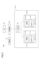
- FIG. 2 is a block diagram of a system configuration including the vehicle lamp according to this embodiment.
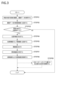
- FIG. 3 is a flow chart illustrating the processing performed in the first to third examples of the first embodiment.
- FIG. 4 is a diagram illustrating a low-beam light distribution pattern emitted by the right lamp unit and the left lamp unit in a first example of the first embodiment.
- FIG. 5 is a diagram illustrating a low-beam light distribution pattern emitted by the right lamp unit and the left lamp unit in a second example of the first embodiment.
- FIG. 1 is a perspective view of a vehicle equipped with a vehicle lamp according to an embodiment of the present disclosure (hereinafter simply referred to as the present embodiment).
- FIG. 2 is a block diagram of a system configuration including the vehicle lamp according to this embodiment.
- FIG. 3 is a flow chart illustrating the processing
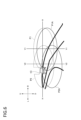
- FIG. 6 is a diagram illustrating light distribution patterns emitted by the right lamp unit and the left lamp unit in a third example of the first embodiment.
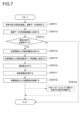
- FIG. 7 is a flow chart illustrating the processing performed in the fourth to sixth examples of the first embodiment.
- FIG. 8 is a diagram illustrating a low-beam light distribution pattern emitted by each lamp unit in a fourth example of the first embodiment.
- FIG. 9 is a diagram illustrating an example of a low-beam light distribution pattern emitted by each lamp unit in a fourth example of the first embodiment.
- FIG. 10 is a diagram illustrating an example of a low-beam light distribution pattern emitted by each lamp unit in a fourth example of the first embodiment.
- FIG. 10 is a diagram illustrating an example of a low-beam light distribution pattern emitted by each lamp unit in a fourth example of the first embodiment.
- FIG. 11 is a diagram illustrating an example of a low-beam light distribution pattern emitted by each lamp unit in a fifth example of the first embodiment.
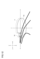
- FIG. 12 is a diagram illustrating a light distribution pattern emitted by each lamp unit in a sixth example of the first embodiment.
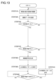
- FIG. 13 is a flow chart illustrating the processing performed in the first example of the second embodiment.
- FIG. 14 is a diagram illustrating an ADB light distribution pattern and a low beam light distribution pattern emitted by the right lamp unit in a first example of the second embodiment.
- FIG. 15 is a diagram illustrating an ADB light distribution pattern and a low beam light distribution pattern emitted by the right lamp unit when the vehicle is traveling in the right lane in the first example of the second embodiment.
- FIG. 16 is a flow chart illustrating the processing performed in the second example of the second embodiment.
- FIG. 17 is a diagram illustrating an ADB light distribution pattern and a low beam light distribution pattern illuminated by the right lamp unit, and an ADB light distribution pattern and a low beam light distribution pattern illuminated by the left lamp unit in a second example of the second embodiment.
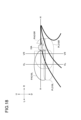
- FIG. 18 is a diagram illustrating an ADB light distribution pattern and a low beam light distribution pattern emitted by the right lamp unit and an ADB light distribution pattern and a low beam light distribution pattern emitted by the left lamp unit when the vehicle is traveling in the right lane in a second example of the second embodiment.
- the "left-right direction,” “up-down direction,” and “front-rear direction” may be mentioned as appropriate. These directions are relative directions set for the vehicle 1 illustrated in FIG. 1.
- the "left-right direction” includes the “left direction” and the “right direction,” and is also the vehicle width direction of the vehicle 1.
- the "up-down direction” includes the “upward direction” and the “downward direction.”
- the "front-rear direction” includes the "forward direction” and the "rearward direction.”
- the front-rear direction is a direction perpendicular to the left-right direction and the up-down direction. Note that in each figure, the symbol U shown in the figure indicates the upward direction.
- the symbol D indicates the downward direction.
- the symbol F indicates the forward direction.
- the symbol B indicates the rearward direction.
- the symbol L indicates the leftward direction.
- the symbol R indicates the rightward direction.
- FIG. 1 is a perspective view of a vehicle 1 equipped with the vehicle lamp 10.
- Figure 2 is a block diagram of a system configuration including the vehicle lamp 10.
- the vehicle 1 is, for example, a vehicle (automobile) capable of running in a manual driving mode and/or an automatic driving mode.
- the vehicle 1 includes a vehicle lamp 10, a camera 20, a steering device 30, and a vehicle control unit 40.
- the vehicle lamp 10 includes a lamp control unit 50, a right lamp unit 60 arranged on the right side of the vehicle 1, and a left lamp unit 70 arranged on the left side of the vehicle 1.
- the right lamp unit 60 is arranged in the lamp chamber of the right headlamp 200R.
- the left lamp unit 70 is arranged in the lamp chamber of the left headlamp 200L.
- the right lamp unit 60 may be provided separately from the right headlamp 200R.
- the left lamp unit 70 may be provided separately from the left headlamp 200L.
- the camera 20 is arranged, for example, near the front window.
- the camera 20 is arranged between the right lamp unit 60 and the left lamp unit 70 in the vehicle width direction (left-right direction in Figure 1) of the vehicle 1.
- the steering device 30 is provided, for example, inside the vehicle 1.
- the right lamp unit 60 comprises a lamp body (not shown), an outer cover (not shown), a right optical unit 61 arranged within a lamp chamber formed by the lamp body and the outer cover, and a right drive unit 62 arranged within the lamp chamber.
- the left lamp unit 70 comprises a lamp body (not shown), an outer cover (not shown), a left optical unit 71 arranged within a lamp chamber formed by the lamp body and the outer cover, and a left drive unit 72 arranged within the lamp chamber.
- the camera 20 is a camera that includes an imaging element such as a CCD (Charge-Coupled Device) or a CMOS (Complementary Metal Oxide Semiconductor).
- the camera 20 captures the surroundings of the vehicle 1 (for example, the area in front of the vehicle 1) to obtain imaging data.
- the camera 20 outputs the imaging data to the vehicle control unit 40.
- the steering device 30 includes, for example, a steering wheel, a shaft, and a rack and pinion mechanism.
- the steering wheel When the steering wheel is rotated clockwise or counterclockwise, the steering device 30 transmits the rotation of the steering wheel via the rack and pinion mechanism through the shaft, and changes the direction of the wheels to the left or right depending on the direction of rotation of the steering wheel.
- the steering device 30 When the steering device 30 is operated to the right while the vehicle 1 is traveling, the vehicle 1 moves to the right.
- the steering device 30 is operated to the left while the vehicle 1 is traveling, the vehicle 1 moves to the left.
- the vehicle control unit 40 is configured to control the running of the vehicle 1.
- the vehicle control unit 40 can be configured to determine the surrounding environment of the vehicle 1 based on surrounding environment information and transmit the determination result to the lamp control unit 50.
- the vehicle control unit 40 is configured, for example, by at least one electronic control unit (ECU: Electronic Control Unit).
- the electronic control unit includes, for example, a computer system including one or more processors and one or more memories, and an electronic circuit composed of active elements such as transistors and passive elements.
- the vehicle control unit 40 is configured to perform image analysis of the imaging data output from the camera 20.
- the vehicle control unit 40 detects surrounding environment information indicating the surrounding environment of the vehicle 1 from the imaging data, and transmits the surrounding environment information to the lamp control unit 50.
- the surrounding environment information is, for example, position information of an object (oncoming vehicle, preceding vehicle, sign, etc.) located in front of the vehicle 1, type information of the object, etc.
- the position information is, for example, an angle coordinate that indicates the orientation of the object as seen from the vehicle 1.
- the vehicle control unit 40 can identify the type of the object and generate type information, for example, by analyzing light emitted from the object or light reflected by the object.
- the vehicle control unit 40 may identify the type of the object and generate type information, for example, based on a change in the distance between the vehicle 1 and the object.
- the vehicle control unit 40 may identify the type of the object and generate type information, based on the analysis result of the light emitted from the object or the light reflected by the object and the change in the distance between the vehicle 1 and the object.
- the lamp control unit 50 may have the same hardware configuration as the vehicle control unit 40.
- the lamp control unit 50 is configured to control the right lamp unit 60 and the left lamp unit 70 based on the surrounding environment information received from the vehicle control unit 40.
- the lamp control unit 50 stores first irradiation area information related to the irradiation area of the right optical unit 61 provided in the right lamp unit 60.
- the first irradiation area information is information indicating an area to which light is irradiated from the right optical unit 61 when the vehicle 1 is traveling straight and there is no object in front of the vehicle 1.
- the first irradiation direction of the right optical unit 61 when there is no object in front of the vehicle 1 is referred to as a first reference direction.
- the lamp control unit 50 also stores second irradiation area information related to the irradiation area of the left optical unit 71 provided in the left lamp unit 70.
- the second irradiation area information is information indicating an area to which light is irradiated from the left optical unit 71 when the vehicle 1 is traveling straight and there is no object in front of the vehicle 1.
- the second irradiation direction of the left optical unit 71 when there is no object in front of the vehicle 1 is referred to as a second reference direction.
- the lamp control unit 50 is configured to displace the first irradiation direction of the right optical unit 61 by a first movement amount by driving the right drive unit 62. Furthermore, the lamp control unit 50 is configured to calculate a first movement amount in the vertical direction of the first irradiation direction based on the position information of the object located in front of the vehicle 1 and the first irradiation area information. Furthermore, the lamp control unit 50 is configured to calculate a first movement amount in the vertical direction of the first irradiation direction based on the type information of the object located in front of the vehicle 1 and the first irradiation area information. The lamp control unit 50 can displace the second irradiation direction of the left optical unit 71 by a second movement amount by driving the left drive unit 72.
- the lamp control unit 50 is configured to calculate a second movement amount in the vertical direction of the second irradiation direction based on the position information of the object located in front of the vehicle 1 and the second irradiation area information. Furthermore, the lamp control unit 50 is configured to calculate a second movement amount in the vertical direction of the second irradiation direction based on the type information of the object located in front of the vehicle 1 and the second irradiation area information. In this embodiment, the lamp control unit 50 calculates the angle by which the first irradiation direction is displaced from the first reference direction as the first movement amount, and calculates the angle by which the second irradiation direction is displaced from the second reference direction as the second movement amount.
- the first reference direction and the second reference direction are set to 0 degrees.
- This 0 degree may be set to coincide with the horizontal direction, or may be set to a predetermined reference angle different from the horizontal direction.
- the first movement amount and the second movement amount when the first irradiation direction and the second irradiation direction are moved upward from the first reference direction and the second reference direction are positive values (angles).
- the first movement amount and the second movement amount when the first irradiation direction and the second irradiation direction are moved downward from the first reference direction and the second reference direction are negative values (angles).
- the absolute value of the first movement amount and the absolute value of the second movement amount are 0 degrees or more and 3 degrees or less.
- the right optical unit 61 is configured to irradiate at least a low beam light distribution pattern.
- the right optical unit 61 is equipped with, for example, a low beam lamp.
- the right optical unit 61 may be configured to irradiate not only a low beam light distribution pattern but also an ADB (Adaptive Driving Beam) light distribution pattern.
- the right optical unit 61 is equipped with a low beam lamp and an ADB high beam lamp.
- the ADB high beam lamp irradiates an ADB light distribution pattern in an area including a position above the low beam light distribution pattern.
- the ADB light distribution pattern is a light distribution pattern that does not irradiate light in an area where an object such as a preceding vehicle or an oncoming vehicle exists in the high beam light distribution pattern, and is a light distribution pattern that changes the non-irradiated area depending on the presence or absence and position of the object.
- the right optical unit 61 is equipped with, for example, at least one light source and a projection lens for projecting the light emitted from the light source to the area in front of the vehicle 1.
- the light source may be, for example, an LED (Light Emitting Diode) element or an LD (Laser Diode) element. If the right optical unit 61 is equipped with an ADB high beam lamp, the light source may be, for example, a micro LED light emitting element.
- the projection lens is, for example, an aspheric lens whose front surface is a convex surface and whose rear surface is a flat surface.
- the projection lens is, for example, formed of a translucent material such as a
- the right optical unit 61 may be composed of, for example, at least one light source, a movable mirror, and an optical system such as lenses and mirrors.
- the movable mirror may be composed of, for example, a DMD (Digital Mirror Device) such as a MEMS (Micro Electro Mechanical Systems) mirror or a rotating blade mirror.
- DMD Digital Mirror Device
- MEMS Micro Electro Mechanical Systems
- the right drive unit 62 is, for example, a leveling actuator.
- the right drive unit 62 includes, for example, a motor as a drive source, and a screw that rotates when the motor is driven.
- the screw included in the right drive unit 62 is, for example, screwed into the right optical unit 61.
- the right drive unit 62 drives, the right optical unit 61 tilts in the vertical direction. In this way, the right drive unit 62 can displace the orientation of the right optical unit 61 in the vertical direction.
- the left optical unit 71 may have the same configuration as the right optical unit 61. However, the left optical unit 71 may be composed of, for example, at least one light source, a drive mirror, and an optical system such as lenses and mirrors. The left optical unit 71 is configured to irradiate at least a low beam light distribution pattern. The left optical unit 71 is equipped with, for example, a low beam lamp. The left optical unit 71 may be configured to irradiate not only the low beam light distribution pattern but also the ADB light distribution pattern. In this case, the left optical unit 71 is equipped with a low beam lamp and an ADB high beam lamp.
- the left drive unit 72 is, for example, a leveling actuator.
- the left drive unit 72 may have a configuration similar to that of the right drive unit 62.
- the left drive unit 72 can tilt the left optical unit 71 in the up-down direction using the same principle as the right drive unit 62. In this way, the left drive unit 72 can displace the orientation of the left optical unit 71 in the up-down direction.
- Fig. 3 is a flow chart illustrating the process performed in this embodiment.
- Fig. 4 is a diagram illustrating the low beam light distribution patterns PL1A, PL2A irradiated by the right lamp unit 60 and the left lamp unit 70 in the first embodiment of the first embodiment.
- the V1-V1 line indicating the vertical direction (up and down direction in Fig.
- the vehicle 1 is traveling in the left lane.
- the vehicle 1 is traveling on a road with no gradient, and the first irradiation direction and the second irradiation direction in the initial state are the first reference direction and the second reference direction, respectively.
- the heights of the first reference direction and the second reference direction match the H-H line.
- the vehicle 1 is approaching a road that curves to the left, and an oncoming vehicle (an example of an object) 1A is present in front of the vehicle 1.
- the oncoming vehicle 1A is traveling in the right lane, which is the oncoming lane, but is on the side of the vehicle's own lane (left side in FIG.
- the low-beam light distribution patterns PL1, PL1A, PL2, and PL2A illustrated in FIG. 4 are shown projected onto a virtual vertical screen at a predetermined position in front of the vehicle 1 (for example, a position 15 m to 20 m in front of the vehicle 1).
- the camera 20 captures an image of the area ahead of the vehicle 1 and obtains image data relating to the area ahead (STEP 01).
- the camera 20 transmits the image data to the vehicle control unit 40 (STEP 02).
- the vehicle control unit 40 performs image analysis of the captured image data and determines whether or not there is an object ahead of the vehicle 1 (STEP 03). If the vehicle control unit 40 determines that there is no object ahead of the vehicle 1 (NO in STEP 03), the vehicle control unit 40 ends the process. If the vehicle control unit 40 determines that there is an object ahead of the vehicle 1 (YES in STEP 03), the vehicle control unit 40 generates position information of the object from the captured image data (STEP 04). In this embodiment, since an oncoming vehicle 1A is ahead of the vehicle 1, the vehicle control unit 40 generates position information of the oncoming vehicle 1A from the captured image data.
- the position information of the oncoming vehicle 1A is, for example, an angle coordinate that represents the orientation of the oncoming vehicle 1A as seen from the vehicle 1 in angle.
- the vehicle control unit 40 transmits the position information of the oncoming vehicle 1A to the lamp control unit 50 (STEP 05).
- the installation positions of the lamp units (right lamp unit 60 and left lamp unit 70) in the vehicle 1 are different from the installation position of the camera 20. Therefore, there is a misalignment (parallax) between the irradiation direction of each lamp unit (first irradiation direction and second irradiation direction) and the imaging direction of the camera 20. For this reason, as illustrated in FIG. 3, when the lamp control unit 50 receives position information of the oncoming vehicle 1A from the vehicle control unit 40, it performs parallax correction on the position information (STEP 06).
- the lamp control unit 50 By performing parallax correction, the lamp control unit 50 generates first position information of the oncoming vehicle 1A with parallax correction in the first irradiation direction and second position information of the oncoming vehicle 1A with parallax correction in the second irradiation direction.
- the lamp control unit 50 calculates the irradiation range of the right lamp unit 60 based on the first position information and the first irradiation area information, and calculates the irradiation range of the left lamp unit 70 based on the second position information and the second irradiation area information (STEP 07). After calculating the irradiation range of the right lamp unit 60 and the irradiation range of the left lamp unit 70, the lamp control unit 50 generates irradiation area information. At this time, the lamp control unit 50 calculates a first movement amount in the up-down direction of the first irradiation direction based on the first position information and the first irradiation area information. The lamp control unit 50 calculates a second movement amount in the up-down direction of the second irradiation direction based on the second position information and the second irradiation area information.
- a low beam light distribution pattern PL1 formed when light is irradiated from the right lamp unit 60 in the first reference direction and a low beam light distribution pattern PL2 formed when light is irradiated from the left lamp unit 70 in the second reference direction will be described.
- the low beam light distribution pattern PL1 and the low beam light distribution pattern PL2 are depicted by dashed lines in FIG. 4.
- the low beam light distribution patterns PL1 and PL2 are irradiated to an area including the headlamp of the oncoming vehicle 1A.
- the vehicle lamp 10 displaces the irradiation range of the low beam light distribution pattern according to the position of the object.
- the range in which the low beam light distribution pattern PL1 overlaps with the oncoming vehicle 1A in the vertical direction is smaller than the range in which the low beam light distribution pattern PL2 overlaps with the oncoming vehicle 1A. Therefore, the distance from the upper end of the low beam light distribution pattern PL1 to the lower end of the headlamp of the oncoming vehicle 1A in the range where the low beam light distribution pattern PL1 overlaps with the oncoming vehicle 1A is shorter than the distance from the upper end of the low beam light distribution pattern PL2 to the lower end of the headlamp of the oncoming vehicle 1A in the range where the low beam light distribution pattern PL2 overlaps with the oncoming vehicle 1A.
- the lamp control unit 50 determines that the first irradiation direction of the right lamp unit 60 should be moved downward by 0.2 degrees, and calculates the first movement amount to be -0.2 degrees. Also, the lamp control unit 50 determines that the second irradiation direction of the left lamp unit 70 should be moved downward by 1 degree, and calculates the second movement amount to be -1 degree.
- the lamp control unit 50 when the lamp control unit 50 calculates the first and second movement amounts, it controls the right drive unit 62 to displace the first irradiation direction by the first movement amount, and controls the left drive unit 72 to displace the second irradiation direction by the second movement amount (STEP 08).
- the first movement amount is -0.2 degrees and the second movement amount is -1 degree, so the lamp control unit 50 moves the orientation of the right optical unit 61 downward by 0.2 degrees and the orientation of the left optical unit 71 downward by 1 degree.
- the first irradiation direction is inclined 0.2 degrees downward from the first reference direction
- the second irradiation direction is inclined 1 degree downward from the second reference direction.
- the lamp control unit 50 controls the right drive unit 62 and the left drive unit 72 individually according to the position of the oncoming vehicle 1A, and as a result, the first irradiation direction and the second irradiation direction are individually displaced downward.
- the processing from STEP 01 to STEP 08 is repeatedly executed while the vehicle 1 is traveling. In other words, while the vehicle 1 is traveling, the illumination range of the low beam light distribution pattern emitted from the vehicle lamp 10 is controlled to change appropriately depending on the presence or absence of an object and the position of the object.
- the low beam distribution patterns PL1A and PL2A that are emitted when the orientation of the right optical unit 61 moves 0.2 degrees downward from the first reference direction and the orientation of the left optical unit 71 moves 1 degree downward from the second reference direction.
- the low beam distribution patterns PL1A and PL2A are drawn with solid lines in FIG. 4. As illustrated in FIG. 4, the low beam distribution pattern PL1A is emitted downward from the low beam distribution pattern PL1, and the low beam distribution pattern PL2A is emitted downward from the low beam distribution pattern PL2.
- the downward movement amount from the low beam distribution pattern PL1 to the low beam distribution pattern PL1A is smaller than the downward movement amount from the low beam distribution pattern PL2 to the low beam distribution pattern PL2A.
- the ranges where the low beam distribution patterns PL1A and PL2A overlap with the oncoming vehicle 1A are both below the headlights of the oncoming vehicle 1A, so glare is suppressed.
- the lamp control unit 50 displaces the first irradiation direction of the low beam light distribution pattern irradiated by the right optical unit 61 and the second irradiation direction of the low beam light distribution pattern irradiated by the left optical unit 71 in the vertical direction individually according to the position of the oncoming vehicle 1A.
- the first irradiation direction and the second irradiation direction can be displaced in the vertical direction individually, so that glare can be suppressed while preventing the long-distance visibility of the vehicle 1 from being unnecessarily impaired. In this way, with the vehicle lamp 10, it is possible to maintain the long-distance visibility of the vehicle while suppressing glare.
- the first movement amount is calculated based on the position of the oncoming vehicle 1A and the first illumination area information
- the second movement amount is calculated based on the position of the oncoming vehicle 1A and the second illumination area information.
- the lamp control unit 50 displaces the first illumination direction by the first movement amount, and displaces the second illumination direction by the second movement amount.
- the movement amount of each illumination direction is calculated based on the position of the oncoming vehicle 1A and the illumination area information of each optical unit (right optical unit 61 and left optical unit 71), it is possible to displace each of the first illumination direction and the second illumination direction by an appropriate movement amount.
- the first movement amount is -0.2 degrees
- the second movement amount is -1 degree.
- the absolute value of the first movement amount is between 0 degrees and 3 degrees with respect to the first reference direction
- the absolute value of the second movement amount is between 0 degrees and 3 degrees with respect to the second reference direction. Therefore, with the vehicle lamp 10, glare can be suppressed without unnecessarily impairing visibility at a distance from the vehicle.
- the lamp control unit 50 individually controls the right drive unit 62, which displaces the orientation of the right optical unit 61 in the vertical direction, and the left drive unit 72, which displaces the orientation of the left optical unit 71 in the vertical direction, depending on the position of the oncoming vehicle 1A.
- the lamp control unit 50 individually controls the orientation of the right optical unit 61 and the orientation of the left optical unit 71 in the vertical direction via the right drive unit 62 and the left drive unit 72.
- the orientation of the right optical unit 61 and the orientation of the left optical unit 71 can be individually displaced in the vertical direction using the right drive unit 62 and the left drive unit 72. Therefore, according to the vehicle lamp 10, the position adjustment in the vertical direction of the irradiation direction of the right optical unit 61 and the left optical unit 71 can be performed with high precision.
- the lamp control unit 50 displaces the first irradiation direction and the second irradiation direction individually in the vertical direction according to the position of the oncoming vehicle 1A. Since the cut-off line of the low beam light distribution pattern is located higher in the left-right direction on the own lane side than on the oncoming lane side, when the oncoming vehicle 1A is on the own lane side, there is a risk that the low beam light distribution pattern will be irradiated by the headlamp of the oncoming vehicle 1A.
- the lamp control unit 50 displaces each irradiation direction individually in the vertical direction according to the position of the oncoming vehicle 1A. Therefore, according to the vehicle lamp 10, it is possible to suppress glare while maintaining visibility at a distance from the vehicle.
- FIG. 5 (Second Example of First Embodiment) Next, the low beam light distribution patterns PL11A and PL12A irradiated in this embodiment will be described with reference to FIG. 3 and FIG. 5.
- This embodiment differs from the first embodiment of the first embodiment in that the vehicle 1 is traveling in the right lane and the low beam light distribution patterns PL11, PL12, PL11A, and PL12A have a right cutoff line higher than a left cutoff line, but the rest is basically the same as the first embodiment of the first embodiment. In this embodiment, the same parts as the first embodiment of the first embodiment will not be described as appropriate.
- FIG. 5 the same parts as the first embodiment of the first embodiment will not be described as appropriate.
- V1-V1 line and the V2-V2 line, and the H-H line are the same as the first embodiment of the first embodiment.
- the vehicle 1 is approaching a road that curves to the right, and an oncoming vehicle 1B is present in front of the vehicle 1.
- the oncoming vehicle 1B is traveling in the left lane, which is the oncoming lane, but is on the side of the vehicle's own lane (on the right side in FIG. 5) rather than the center in the left-right direction in front of the vehicle 1.
- STEP 07 will be described. Note that in STEP 07 of this embodiment, the same processing as in STEP 07 of the first embodiment of the first embodiment is executed.
- the low beam distribution pattern PL11 formed when light is irradiated from the right lamp unit 60 in the first reference direction and the low beam distribution pattern PL12 formed when light is irradiated from the left lamp unit 70 in the second reference direction will be described. Note that the low beam distribution pattern PL11 and the low beam distribution pattern PL12 are drawn with dashed lines in FIG. 5. As illustrated in FIG.
- the range in which the low beam distribution pattern PL11 overlaps with the oncoming vehicle 1B in the vertical direction is larger than the range in which the low beam distribution pattern PL12 overlaps with the oncoming vehicle 1B. Therefore, the distance from the upper end of the low beam distribution pattern PL11 to the lower end of the headlamp of the oncoming vehicle 1B in the range where the low beam distribution pattern PL11 overlaps with the oncoming vehicle 1B is longer than the distance from the upper end of the low beam distribution pattern PL12 to the lower end of the headlamp of the oncoming vehicle 1B in the range where the low beam distribution pattern PL12 overlaps with the oncoming vehicle 1B.
- the lamp control unit 50 determines that the first irradiation direction of the right lamp unit 60 should be moved downward by 1 degree, and calculates the first movement amount to be -1 degree. Also, the lamp control unit 50 determines that the second irradiation direction of the left lamp unit 70 should be moved downward by 0.2 degrees, and calculates the second movement amount to be -0.2 degrees.
- the first movement amount is -1 degree and the second movement amount is -0.2 degrees, so the lamp control unit 50 moves the orientation of the right optical unit 61 downward by 1 degree and the orientation of the left optical unit 71 downward by 0.2 degrees.
- the first irradiation direction is tilted downward by 1 degree from the first reference direction
- the second irradiation direction is tilted downward by 0.2 degrees from the second reference direction. Note that in this embodiment as well, the processes from STEP 01 to STEP 08 are repeatedly executed while the vehicle 1 is traveling.
- the low beam distribution patterns PL11A and PL12A that are irradiated when the orientation of the right optical unit 61 moves downward by 1 degree from the first reference direction and the orientation of the left optical unit 71 moves downward by 0.2 degrees from the second reference direction will be described.
- the low beam distribution patterns PL11A and PL12A are drawn with solid lines in FIG. 5. As illustrated in FIG. 5, the low beam distribution pattern PL11A is irradiated downward from the low beam distribution pattern PL11, and the low beam distribution pattern PL12A is irradiated downward from the low beam distribution pattern PL12.
- the downward movement amount from the low beam distribution pattern PL11 to the low beam distribution pattern PL11A is greater than the downward movement amount from the low beam distribution pattern PL12 to the low beam distribution pattern PL12A.
- the vehicle lamp 10 moves the first and second irradiation directions by the amount necessary to suppress glare, so long-distance visibility is not unnecessarily impaired.
- the vehicle lamp 10 also provides the same effects as the first embodiment of the first embodiment.
- FIG. 6 shows the light distribution patterns P1A and P2A irradiated in this embodiment.
- This embodiment differs from the first embodiment in that the right optical unit 61 and the left optical unit 71 irradiate not only the low beam light distribution pattern but also the ADB light distribution pattern, and in that the processes from STEP01 to STEP09 are executed.
- the other aspects are basically the same as the first embodiment.
- the same parts as the first embodiment of the first embodiment will not be described as appropriate.
- FIG. 6 also illustrates the V1-V1 line and the V2-V2 line, and the H-H line, which are the same as the first embodiment of the first embodiment.
- the vehicle 1 is approaching a road that curves to the left, and an oncoming vehicle 1C is present in front of the vehicle 1.
- the oncoming vehicle 1C is traveling in the right lane, which is the oncoming lane, but is on the side of the vehicle's own lane (the left side in FIG. 6) rather than the center in the left-right direction in front of the vehicle 1.
- the light distribution patterns P1, P1A, P2, and P2A include a low-beam light distribution pattern and an ADB light distribution pattern.
- the low-beam light distribution patterns included in the light distribution patterns P1, P1A, P2, and P2A are similar to the low-beam light distribution patterns PL1, PL1A, PL2, and PL2A of the first embodiment of the first embodiment.
- STEP 01 to STEP 09 shown in FIG. 3 are executed.
- STEP 01 to STEP 06 are the same as those in the first embodiment of the first embodiment.
- the irradiation range information generated by the lamp control unit 50 in STEP 07 includes information for distinguishing between a range in which the ADB light distribution pattern should be irradiated and a range in which the ADB light distribution pattern should not be irradiated.
- a light distribution pattern P1 formed when light is irradiated from the right lamp unit 60 in the first reference direction and a light distribution pattern P2 formed when light is irradiated from the left lamp unit 70 in the second reference direction will be described.
- the light distribution pattern P1 and the light distribution pattern P2 are depicted by dashed lines in FIG. 6.
- the low beam light distribution patterns included in the light distribution patterns P1 and P2 are similar to the low beam light distribution patterns PL1 and PL2 of the first embodiment of the first embodiment.
- the range in which the low beam light distribution pattern included in the light distribution pattern P1 overlaps with the oncoming vehicle 1C is smaller than the range in which the low beam light distribution pattern included in the light distribution pattern P2 overlaps with the oncoming vehicle 1C, so that the absolute value of the first movement amount is smaller than the absolute value of the second movement amount.
- the first movement amount and the second movement amount calculated by the lamp control unit 50 in this embodiment are similar to the first movement amount and the second movement amount in the first embodiment of the first embodiment.
- the ADB light distribution pattern is controlled and formed so that it is not irradiated onto areas where oncoming vehicles are present, so as shown in FIG. 6, the ADB light distribution patterns included in light distribution patterns P1 and P2 are not irradiated onto oncoming vehicle 1C.
- STEP 08 in this example is the same as STEP 08 in the first example of the first embodiment.
- STEP 09 will be described.
- the lamp control unit 50 controls the turning on and off of each light source of the ADB high beam lamp based on the irradiation range information generated in STEP 07 (STEP 09).
- the ADB light distribution pattern is not irradiated to the area where the oncoming vehicle 1C is present.
- the processes from STEP 01 to STEP 09 are repeatedly executed while the vehicle 1 is traveling. In other words, while the vehicle 1 is traveling, the irradiation range of the light distribution pattern irradiated from the vehicle lamp 10 is controlled to change appropriately depending on the presence or absence of an object and the position of the object.
- the light distribution patterns P1A and P2A include a low beam light distribution pattern and an ADB light distribution pattern.
- the low beam light distribution pattern is emitted below the headlamp of the oncoming vehicle 1C in the vertical direction according to the principle explained in the first embodiment of the first embodiment.
- the ADB light distribution pattern is not emitted in the area where the oncoming vehicle 1C is present. Therefore, even in this embodiment, glare is suppressed by the vehicle lamp 10.
- the vehicle lamp 10 moves the first irradiation direction and the second irradiation direction by an amount necessary to suppress glare, so that long-distance visibility is not unnecessarily impaired.
- the vehicle lamp 10 also provides the same effects as the first embodiment of the first embodiment.
- the right optical unit 61 and the left optical unit 71 can emit not only a low beam light distribution pattern but also an ADB light distribution pattern.
- ADB high beam lamps which emit light to an area including a position above the low beam light distribution pattern, are more likely to produce glare than low beam lamps.
- glare can be suppressed while maintaining visibility at a distance from the vehicle by controlling the above embodiment.
- FIG. 7 is a flow chart illustrating the process performed in this embodiment.
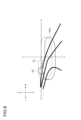
- FIG. 8 is a diagram illustrating the low beam light distribution patterns PL, PLA that each lamp unit can irradiate in this embodiment.
- the right optical unit 61 irradiates the low beam light distribution pattern PLA.
- FIG. 8 illustrates a V-V line indicating the vertical direction (up and down direction in FIG. 8) of the center of the irradiation range of the right lamp unit 60, and an H-H line perpendicular to the V-V line and extending in the horizontal direction (left and right direction in FIG. 8).
- the V-V line is an example of the center in the left and right direction in front of the vehicle 1.
- the vehicle 1 is traveling in the left lane.
- the vehicle 1 is traveling on a road with no gradient, and the first irradiation direction in the initial state is the first reference direction.
- the height of the first reference direction coincides with the H-H line.
- the vehicle 1 is approaching a road that curves to the left, and an oncoming vehicle (an example of an object) 1A is present in front of the vehicle 1.
- the oncoming vehicle 1D is traveling in the right lane, which is the oncoming lane, but is on the side of the vehicle's own lane (left side in FIG. 8) of the V-V line (the center in the left-right direction in front of the vehicle 1).
- the low beam light distribution patterns PL, PLA illustrated in FIG. 8 are shown projected onto a virtual vertical screen at a predetermined position in front of the vehicle 1 (for example, a position 25 m in front of the vehicle 1).
- the vehicle 1 is traveling at 65 km/h
- the oncoming vehicle 1D is traveling at 60 km/h.
- descriptions of parts that are similar to those in the first example of the first embodiment will be omitted where appropriate.
- STEP 11 and STEP 12 are similar to STEP 01 and STEP 02 in the first example of the first embodiment.
- the vehicle control unit 40 performs image analysis of the captured image data and determines whether or not there is an object ahead of the vehicle 1 (STEP 13). If the vehicle control unit 40 determines that there is no object ahead of the vehicle 1 (NO in STEP 13), the vehicle control unit 40 ends the process. If the vehicle control unit 40 determines that there is an object ahead of the vehicle 1 (YES in STEP 13), the vehicle control unit 40 generates position information and type information of the object from the captured image data (STEP 14). In this embodiment, since there is an oncoming vehicle 1D ahead of the vehicle 1, the vehicle control unit 40 generates position information and type information of the oncoming vehicle 1D from the captured image data.
- the position information of the oncoming vehicle 1D is, for example, an angle coordinate that represents the orientation of the oncoming vehicle 1D as seen from the vehicle 1 in terms of an angle.
- the type information of the oncoming vehicle 1D is information that indicates that the oncoming vehicle 1D is an oncoming vehicle to the vehicle 1.
- the vehicle control unit 40 identifies the type of the oncoming vehicle 1D based on the analysis result of the light emitted from the oncoming vehicle 1D and the change in the distance between the vehicle 1 and the oncoming vehicle 1D, and generates type information. For example, when the light emitted from the object is white, the vehicle control unit 40 determines that the object is an oncoming vehicle. For example, when the light emitted from the object is red, the vehicle control unit 40 determines that the object is a leading vehicle. For example, when the light emitted from the vehicle lamp 10 is reflected by the object by retroreflection, the vehicle control unit 40 determines that the object is a sign.
- the vehicle control unit 40 determines that the object is an oncoming vehicle. For example, when the vehicle 1 is approaching or moving away from the object slower or slightly faster than the speed of the vehicle 1, the vehicle control unit 40 determines that the object is a leading vehicle. If vehicle 1 is approaching the object at the same speed as vehicle 1, vehicle control unit 40 determines that the object is a sign. In this embodiment, vehicle control unit 40 determines that the object is an oncoming vehicle based on the fact that the light emitted from the object is white and that vehicle 1 is approaching the object at a speed significantly faster than vehicle 1 (125 km/h in this case). Vehicle control unit 40 transmits position information and type information of oncoming vehicle 1D to lamp control unit 50 (STEP 15).
- the installation positions of the lamp units (right lamp unit 60 and left lamp unit 70) in the vehicle 1 are different from the installation position of the camera 20, so there is a misalignment (parallax) between the irradiation direction of each lamp unit and the imaging direction of the camera 20.
- the lamp control unit 50 receives position information of the oncoming vehicle 1D from the vehicle control unit 40, it performs parallax correction on the position information (STEP 16). For example, by performing parallax correction, the lamp control unit 50 generates first position information of the oncoming vehicle 1D that has been parallax-corrected in the first irradiation direction.
- the lamp control unit 50 calculates the illumination range of the right lamp unit 60 based on the type information and the first illumination area information (STEP 17). After calculating the illumination range of the right lamp unit 60, the lamp control unit 50 generates illumination range information. At this time, the lamp control unit 50 calculates a first movement amount in the up-down direction of the first illumination direction based on the type information and the first illumination area information. Since the object in this embodiment is the oncoming vehicle 1D, the lamp control unit 50 determines that the first illumination direction of the right lamp unit 60 needs to be moved downward by 1 degree, and calculates the first movement amount to be -1 degree. The lamp control unit 50 also calculates the second movement amount to be -1 degree.
- the lamp control unit 50 When the lamp control unit 50 calculates the first movement amount, it controls the right drive unit 62 to displace the first irradiation direction by the first movement amount (STEP 18). In STEP 18, the lamp control unit 50 also controls the left drive unit 72 in the same way as it controls the right drive unit 62. In this embodiment, since the object is an oncoming vehicle 1D, the lamp control unit 50 controls the right drive unit 62 to displace the first irradiation direction downward by one degree. As a result, the first irradiation direction is tilted downward by one degree from the first reference direction. In this way, the lamp control unit 50 controls the right drive unit 62 according to the type of oncoming vehicle 1D, and as a result, the first irradiation direction is displaced downward. In STEP 18, the lamp control unit 50 also controls the left drive unit 72 in the same way as it controls the right drive unit 62, so that the second irradiation direction is tilted downward by one degree from the second reference direction.
- the low beam light distribution pattern PL formed when light is irradiated from the right lamp unit 60 in the first reference direction and the low beam light distribution pattern PLA irradiated when the orientation of the right optical unit 61 moves downward from the first reference direction by one degree will be described.
- the low beam light distribution pattern PL is drawn with a dashed line
- the low beam light distribution pattern PLA is drawn with a solid line.
- the low beam light distribution pattern PL is irradiated to an area including the headlights of the oncoming vehicle 1D.
- the vehicle lamp 10 displaces the irradiation range of the low beam light distribution pattern according to the type of object.
- the low beam light distribution pattern PL when the low beam light distribution pattern PL is irradiated, the low beam light distribution pattern PL is irradiated to an area above the headlights of the oncoming vehicle 1D in the vertical direction. Therefore, when the low beam light distribution pattern PL is irradiated, it gives glare to the oncoming vehicle 1D.
- the low beam light distribution pattern PLA when the low beam light distribution pattern PLA is irradiated, the low beam light distribution pattern PLA is irradiated to an area below the headlamp of the oncoming vehicle 1D, so glare is suppressed. Also, the maximum illuminance of light that is permissible when irradiating an oncoming vehicle is smaller than the maximum illuminance of light that is permissible when irradiating a leading vehicle. Furthermore, if the irradiation direction of the low beam light distribution pattern is shifted downward by one degree, it becomes easier to suppress the glare given to oncoming vehicles, so in this embodiment, the amount of downward movement of the irradiation direction of the low beam light distribution pattern when the target object is an oncoming vehicle is set to one degree.
- the processing from STEP 11 to STEP 18 is repeatedly executed while the vehicle 1 is traveling.
- the illumination range of the low beam light distribution pattern emitted from the vehicle lamp 10 is controlled to change appropriately depending on the presence or absence of an object and the type of object.
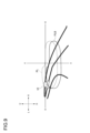
- the low beam light distribution pattern PLB that is illuminated when the target object is a preceding vehicle 1E.
- the preceding vehicle 1E is traveling in the same lane as vehicle 1, and is therefore on the vehicle lane side of line V-V (on the left side in Figure 9). Furthermore, vehicle 1 is traveling at 65 km/h, and the preceding vehicle 1E is traveling at 60 km/h.
- steps 11 to 13 are performed in the same manner as described above.
- the vehicle control unit 40 In STEP 14, the vehicle control unit 40 generates position information and type information of the vehicle 1E in front. The vehicle control unit 40 determines that the object is a vehicle in front based on the fact that the light emitted from the object is red and that the vehicle 1 is approaching the object slower than the speed of the vehicle 1 (in this case, 5 km/h).
- STEP 15 and STEP 16 are the same as described above.
- the lamp control unit 50 determines that the first illumination direction of the right lamp unit 60 should be moved downward by 0.3 degrees, and calculates the first movement amount to be -0.3 degrees. The lamp control unit 50 also calculates the second movement amount to be -0.3 degrees.
- the lamp control unit 50 controls the right drive unit 62 so as to displace the first irradiation direction by 0.3 degrees (STEP 18). As a result, the first irradiation direction is tilted 0.3 degrees downward from the first reference direction. Note that in STEP 18, the lamp control unit 50 also controls the left drive unit 72 in the same way as it controls the right drive unit 62, so that the second irradiation direction is tilted 0.3 degrees downward from the second reference direction.
- the low beam distribution pattern PL formed when light is irradiated from the right lamp unit 60 in the first reference direction, and the low beam distribution pattern PLB irradiated when the orientation of the right optical unit 61 moves 0.3 degrees downward from the first reference direction.
- the low beam distribution pattern PL is drawn with a dashed line
- the low beam distribution pattern PLB is drawn with a solid line.
- the low beam distribution pattern PL when the low beam distribution pattern PL is irradiated, the low beam distribution pattern PL is irradiated up to an area above the tail lamp of the vehicle in front 1E in the vertical direction. For this reason, when the low beam distribution pattern PL is irradiated, it causes glare to the vehicle in front 1E.
- the low beam light distribution pattern PLB when the low beam light distribution pattern PLB is irradiated, the low beam light distribution pattern PLB is irradiated to an area below the tail lamp of the preceding vehicle 1E, so glare is suppressed.
- the absolute value of the first movement amount when the object is a preceding vehicle is set smaller than the absolute value of the first movement amount when the object is an oncoming vehicle.
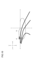
- sign 1F is installed on the roadside of the right lane, so it is on the side of the vehicle's own lane (left side in Figure 10) than the V-V line. Furthermore, vehicle 1 is traveling at 65 km/h.
- steps 11 to 13 are performed in the same manner as described above.
- the vehicle control unit 40 In STEP 14, the vehicle control unit 40 generates position information and type information of the sign 1F. In this embodiment, the vehicle control unit 40 determines that the object is a sign based on the fact that the light emitted from the vehicle lamp 10 is reflected by the object due to retroreflection, and that the vehicle 1 is approaching the object at the same speed as the vehicle 1 (65 km/h in this case).
- STEP 15 and STEP 16 are the same as described above.
- the lamp control unit 50 determines that the first irradiation direction will not be moved in the right lamp unit 60, and calculates the first movement amount to 0 degrees.
- the lamp control unit 50 also calculates the second movement amount to 0 degrees.
- the lamp control unit 50 controls the right drive unit 62 so as to keep the first irradiation direction the first reference direction (STEP 18). As a result, the first irradiation direction does not deviate from the first reference direction. Note that in STEP 18, the lamp control unit 50 also controls the left drive unit 72 in the same way as it controls the right drive unit 62, so that the second irradiation direction does not deviate from the second reference direction.
- the low beam light distribution pattern PL in which light is irradiated from the right lamp unit 60 in the first reference direction.
- the low beam light distribution pattern PL is irradiated, the low beam light distribution pattern PL is irradiated over most of the area of the sign 1F in the vertical direction.
- the object is a sign, no glare occurs, so there is no need to move the first irradiation direction downward from the first reference direction so that, for example, the low beam light distribution pattern PL is irradiated to the lower side of the sign 1F.
- the lamp control unit 50 displaces the irradiation direction of the low beam light distribution pattern irradiated by each optical unit (right optical unit 61 and left optical unit 71) in the vertical direction according to the type of object. Since the cutoff line of the low beam light distribution pattern is located higher on the own lane side than on the oncoming lane side in the left-right direction, for example, when an oncoming vehicle 1D is on the own lane side, there is a risk that the low beam light distribution pattern will be irradiated to the oncoming vehicle 1D.
- the maximum illuminance of light that is permissible when irradiating an oncoming vehicle is smaller than the maximum illuminance of light that is permissible when irradiating a leading vehicle, for example, when the object is an oncoming vehicle, the need to suppress glare is relatively high compared to when the object is a leading vehicle. Therefore, it is preferable that the downward movement amount of the irradiation direction of the low beam light distribution pattern when the object is an oncoming vehicle is larger than the downward movement amount of the irradiation direction of the low beam light distribution pattern when the object is a leading vehicle.
- the irradiation direction of the low beam light distribution pattern is moved downward, the more the distant visibility in front of the vehicle 1 decreases, so it is not preferable to move the irradiation direction of the low beam light distribution pattern downward more than necessary.
- the irradiation direction of the low beam light distribution pattern is appropriately displaced in the vertical direction depending on the type of object, so it is possible to maintain the distant visibility of the vehicle and suppress glare at the same time.
- the type of object is determined based on the light emitted from or reflected by the object and the change in the distance between the vehicle 1 and the object, making it easy to determine the type of object.
- the lamp control unit 50 calculates a first amount of movement in the up-down direction of the first reference direction, which is the first illumination direction when there is no object in front of the vehicle 1. Since the first amount of movement is -1 degree, i.e., the absolute value of the first amount of movement is between 0 degrees and 3 degrees with respect to the first reference direction, it is possible to suppress glare while not unnecessarily impairing visibility at a distance from the vehicle. In this way, with the vehicle lamp 10, it is possible to maintain visibility at a distance from the vehicle while suppressing glare.
- the type of object is either an oncoming vehicle, a vehicle ahead, or a sign.
- the object is an oncoming vehicle or a vehicle ahead, it is necessary to suppress glare while not unnecessarily reducing visibility at a distance from the vehicle, but when the object is a sign, no glare occurs.
- the need to suppress glare differs depending on the type of object.
- the irradiation direction of the low beam light distribution pattern is appropriately displaced in the vertical direction depending on the type of object, so it is possible to maintain visibility at a distance from the vehicle and suppress glare at the same time.
- the lamp control unit 50 when the object is an oncoming vehicle or a preceding vehicle, the lamp control unit 50 displaces downward the reference direction (first reference direction and second reference direction), which is the illumination direction (first illumination direction and second illumination direction) when there is no object in front of the vehicle 1.
- the lamp control unit 50 when the object is a sign, the lamp control unit 50 does not displace the first illumination direction and the second illumination direction in the vertical direction from the first reference direction and the second reference direction.
- the lamp control unit 50 suppresses glare by displacing the first illumination direction and the second illumination direction in the vertical direction from the first reference direction and the second reference direction.
- the lamp control unit 50 does not displace the first illumination direction and the second illumination direction in the vertical direction from the first reference direction and the second reference direction, so that the visibility of the vehicle 1 at a distance is not reduced.
- the first and second illumination directions are displaced vertically from the first and second reference directions appropriately depending on the type of object, making it possible to maintain visibility at a distance from the vehicle while suppressing glare.
- FIG. 11 also illustrates the V-V line and the H-H line similar to those in the fourth embodiment.
- the oncoming vehicle 1G is traveling in the left lane, which is the oncoming lane, but is on the side of the vehicle's own lane (the right side in FIG. 11) of the V-V line.
- steps 11 to 18 are the same as in the fourth embodiment.
- the low beam light distribution pattern PLC formed when light is irradiated from the right lamp unit 60 in the first reference direction, and the low beam light distribution pattern PLD irradiated when the orientation of the right optical unit 61 moves one degree downward from the first reference direction.
- the low beam light distribution pattern PLC is drawn with a dashed line
- the low beam light distribution pattern PLD is drawn with a solid line.
- the low beam light distribution pattern PLC when the low beam light distribution pattern PLC is irradiated, the low beam light distribution pattern PLC is irradiated up to an area above the headlamp of the oncoming vehicle 1G in the vertical direction. For this reason, when the low beam light distribution pattern PLC is irradiated, it causes glare to the oncoming vehicle 1G.
- the low beam light distribution pattern PLD when the low beam light distribution pattern PLD is irradiated, the low beam light distribution pattern PLD is irradiated to an area below the headlamp of the oncoming vehicle 1G, so glare is suppressed.
- the amount of downward movement of the irradiation direction of the low beam light distribution pattern when the object is an oncoming vehicle is set to 1 degree. Therefore, according to the vehicle lamp 10, the first irradiation direction and the second irradiation direction can be displaced by an appropriate amount according to the type of object, so that long-distance visibility is not unnecessarily impaired.
- the processes from STEP 11 to STEP 18 are executed repeatedly while the vehicle 1 is traveling.
- the process of lowering the illumination direction when the object is a vehicle ahead and the process of not lowering the illumination direction when the object is a sign are also the same as in the fourth embodiment.
- the vehicle lamp 10 achieves the same effects as in the fourth embodiment.
- FIG. 12 shows the same V-V line and H-H line as the fourth embodiment. As illustrated in FIG.
- the oncoming vehicle 1H is traveling in the right lane, which is the oncoming lane, but is on the own lane side (left side in FIG. 12) of the V-V line.
- the light distribution patterns P, PA include the low beam light distribution pattern and the ADB light distribution pattern, and the low beam light distribution pattern is the same as the low beam light distribution patterns PL, PLA of the fourth embodiment.
- the irradiation range information generated by the lamp control unit 50 in STEP 17 includes information for distinguishing between a range in which the ADB light distribution pattern should be irradiated and a range in which the ADB light distribution pattern should not be irradiated, depending on the position and type of the target object.
- STEP 18 in this embodiment is the same as STEP 18 in the fourth embodiment.
- STEP 19 will be described.
- the lamp control unit 50 controls the turning on and off of each light source of the ADB high beam lamp based on the irradiation range information generated in STEP 17 (STEP 19).
- the ADB light distribution pattern is not irradiated onto the area where the oncoming vehicle 1H is present.
- the light distribution pattern P formed when light is emitted from the right lamp unit 60 in the first reference direction, and the light distribution pattern PA emitted when the orientation of the right optical unit 61 moves one degree downward from the first reference direction.
- the light distribution pattern P is drawn with dashed lines, and the light distribution pattern PA is drawn with solid lines.
- the low beam light distribution pattern included in the light distribution pattern P is similar to the low beam light distribution pattern PL of the fourth embodiment.
- the ADB light distribution pattern is formed in such a way that, in principle, it is not irradiated onto areas where oncoming vehicles are present, so that, as shown in the example of FIG. 12, when light distribution pattern P is irradiated, the ADB light distribution pattern included in light distribution pattern P is not irradiated onto oncoming vehicle 1H.
- the low beam light distribution pattern included in light distribution pattern P is irradiated up to an area above the headlights of oncoming vehicle 1H in the vertical direction. For this reason, when light distribution pattern P is irradiated, it causes glare to oncoming vehicle 1H.
- the amount of downward movement of the irradiation direction of the low beam light distribution pattern when the object is an oncoming vehicle is set to 1 degree. Therefore, according to the vehicle lamp 10, the first irradiation direction and the second irradiation direction can be displaced by an appropriate amount according to the type of object, so that long-distance visibility is not unnecessarily impaired.
- the processes from STEP 11 to STEP 19 are executed repeatedly while the vehicle 1 is traveling.
- the process of lowering the illumination direction when the object is a vehicle ahead and the process of not lowering the illumination direction when the object is a sign are also the same as in the fourth embodiment.
- the vehicle lamp 10 achieves the same effects as in the fourth embodiment.
- a vehicle lamp 110 according to this embodiment will be described below with reference to Figures 1 and 2.
- the same components as those of the vehicle lamp 10 according to the first embodiment are denoted by the same reference numerals, and their description will be omitted.
- the vehicle 100 according to this embodiment is different from the vehicle 1 according to the first embodiment in that it includes the vehicle lamp 110 instead of the vehicle lamp 10.
- the vehicle lamp 110 according to this embodiment is different from the vehicle lamp 10 according to the first embodiment in that it includes a right lamp unit 160 and a left lamp unit 170 instead of the right lamp unit 60 and the left lamp unit 70.
- the right lamp unit 160 comprises a lamp body (not shown), an outer cover (not shown), a right optical unit 161 arranged within the lamp chamber formed by the lamp body and the outer cover, and a right drive unit 162 arranged within the lamp chamber.
- the left lamp unit 170 comprises a lamp body (not shown), an outer cover (not shown), a left optical unit 171 arranged within the lamp chamber formed by the lamp body and the outer cover, and a left drive unit 172 arranged within the lamp chamber.
- the right optical unit 161 is configured to irradiate at least an ADB (Adaptive Driving Beam) light distribution pattern.
- the right optical unit 161 is provided with, for example, an ADB high beam lamp.
- the right optical unit 161 may be configured to irradiate not only the ADB light distribution pattern but also a low beam light distribution pattern.
- the right optical unit 161 is provided with an ADB high beam lamp and a low beam lamp.
- the low beam lamp irradiates a low beam light distribution pattern in an area including a position below the ADB light distribution pattern.
- the right optical unit 161 is provided with, for example, a light source and a projection lens similar to the light source and projection lens provided in the right optical unit 61 according to the first embodiment.
- the light source of the right optical unit 161 may be composed of, for example, a micro LED light emitting element as the light source of the ADB high beam lamp.
- the right optical unit 161 may be composed of, for example, at least one light source, a driving mirror, and an optical system such as a lens or mirror.
- the right drive unit 162 is, for example, a leveling actuator.
- the right drive unit 162 is equipped with, for example, a motor and a screw similar to the motor and screw equipped in the right drive unit 62 according to the first embodiment.
- the right drive unit 162 can displace the orientation of the right optical unit 161 in the vertical direction based on the same principle as the right drive unit 62 according to the first embodiment displaces the orientation of the right optical unit 61 in the vertical direction.
- the configuration of the left lamp unit 170 is similar to that of the right lamp unit 160, so a description will be omitted.
- Fig. 13 is a flow chart illustrating the processing performed in the first embodiment of the second embodiment.
- Fig. 14 is a diagram illustrating the ADB light distribution pattern PA3 and the low beam light distribution pattern PL3 irradiated by the right lamp unit 160 in the first embodiment of the second embodiment.
- the right optical unit 161 irradiates the ADB light distribution pattern PA3.
- the right optical unit 161 also irradiates the low beam light distribution pattern PL3.
- the ADB light distribution pattern and the low beam light distribution pattern irradiated by the left lamp unit 170 are the same as the ADB light distribution pattern PA3 and the low beam light distribution pattern PL3 irradiated by the right lamp unit 160, the following describes the case where the right lamp unit 160 irradiates the ADB light distribution pattern PA3 and the low beam light distribution pattern PL3, and the description of the left lamp unit 170 is omitted.
- 14 also shows a line V-V indicating the vertical direction (the up-down direction in FIG. 14) of the center of the illumination range of the right lamp unit 160, and a line H-H perpendicular to the line V-V and extending in the horizontal direction (the left-right direction in FIG. 14).
- the line V-V is an example of the center in the left-right direction in front of the vehicle 100.
- FIG. 14 illustrates, with dashed lines, an ADB light distribution pattern PA3 formed when light is irradiated from the right lamp unit 160 in the initial state.
- FIG. 144 illustrates, with solid lines, a low beam light distribution pattern PL3 formed when light is irradiated from the right lamp unit 160 in this embodiment.
- the ADB light distribution pattern PA3 and low beam light distribution pattern PL3 illustrated in FIG. 14 are shown projected onto a virtual vertical screen at a predetermined position in front of the vehicle 100 (for example, a position 25 m in front of the vehicle 100).
- the camera 20 captures an image of the area ahead of the vehicle 100 and obtains image data relating to the area ahead (STEP 310).
- the camera 20 may capture an image of the area ahead of the vehicle 100 at predetermined time intervals.
- the camera 20 transmits the image data to the vehicle control unit 40 (STEP 320).
- the vehicle control unit 40 performs image analysis on the captured image data and determines whether or not an oncoming vehicle 10A is present (STEP 330). If the vehicle control unit 40 determines that there is no oncoming vehicle 10A (NO in STEP 330), the vehicle control unit 40 returns the process to STEP 310. If the vehicle control unit 40 determines that there is an oncoming vehicle 10A (YES in STEP 330), a signal indicating this is sent to the lamp control unit 50 and the process proceeds.
- the vehicle control unit 40 also determines whether the vehicle 100 will turn (STEP 370). For example, the vehicle control unit 40 may receive a signal from the steering device 30 indicating that the steering device 30 has been operated, and when the vehicle control unit 40 receives the signal, it may determine that the vehicle 100 will turn. For example, the vehicle control unit 40 may perform image analysis of the imaging data received from the camera 20 and determine whether the lane in which the vehicle 100 is traveling is curving ahead of the vehicle 100. For example, the vehicle control unit 40 may determine whether the lane in which the vehicle 100 is traveling is curving ahead of the vehicle 100 based on the position information and map information of the vehicle 100 from a GPS (not shown) or a memory unit (not shown).
- a GPS not shown
- a memory unit not shown
- the vehicle control unit 40 determines that the vehicle 100 will turn when it determines that the vehicle 100 will travel with a predetermined curvature radius or less. If the vehicle control unit 40 determines that the vehicle 100 will turn (YES in STEP 370), the vehicle control unit 40 sends a signal indicating this to the lamp control unit 50 and proceeds with the process. If the vehicle control unit 40 determines that the vehicle 100 will not turn (NO in STEP 370), the vehicle control unit 40 returns the process to STEP 310.
- the lamp control unit 50 calculates the illumination range of the right lamp unit 160 based on the first illumination area information, and calculates the illumination range of the left lamp unit 170 based on the second illumination area information. After calculating the illumination ranges of the right lamp unit 160 and the left lamp unit 170, the lamp control unit 50 generates illumination range information.
- the illumination range information is information for distinguishing between an area where the low beam light distribution pattern should be illuminated and an area where the low beam light distribution pattern should not be illuminated within the range that the vehicle lamp 110 can illuminate.
- the lamp control unit 50 when the lamp control unit 50 receives a signal indicating that there is an oncoming vehicle 10A and a signal indicating that the vehicle 100 is turning from the vehicle control unit 40, it generates a control signal to turn off the ADB light distribution pattern PA3 of the right lamp unit 160 (STEP 380). After that, the lamp control unit 50 transmits the generated control signal to the right optical unit 161.
- the right optical unit 161 which has received the control signal, turns off the ADB light distribution pattern PA3 of the right lamp unit 160 and continues to irradiate the low beam light distribution pattern PL3 (STEP 390). For example, the right optical unit 161 turns off the ADB light distribution pattern PA3 irradiated from the right optical unit 161 by turning off all of the micro LED light emitting elements that are the light sources of the ADB high beam lamp. Furthermore, the right optical unit 161 maintains the irradiation of the low beam light distribution pattern PL3 irradiated from the right optical unit 161.
- the off-time T1 during which the ADB light distribution pattern PA3 switches from a turned-on state to a turned-off state is relatively short.
- the off-time T1 is, for example, less than 1 second.
- the off-time T1 is shorter than the on-time T2 during which the ADB light distribution pattern PA3 switches from a turned-off state to a turned-on state, which will be described later.
- the vehicle control unit 40 judges whether the vehicle 100 has finished turning (STEP 400). If the vehicle control unit 40 judges that the vehicle 100 has not finished turning (NO in STEP 400), the vehicle control unit 40 returns the process to before STEP 400. If the vehicle control unit 40 judges that the vehicle 100 has finished turning (YES in STEP 400), it sends a signal indicating that to the lamp control unit 50.
- the lamp control unit 50 that receives the signal controls the right optical unit 161 to irradiate the ADB light distribution pattern PA3 from the right lamp unit 160 (STEP 410). For example, the right optical unit 161 irradiates the ADB light distribution pattern PA3 irradiated from the right optical unit 161 by turning on the micro LED. At this time, the lighting time T2 during which the ADB light distribution pattern PA3 is switched from the off state to the on state is relatively long. The lighting time T2 is, for example, 3 seconds or more.
- the lamp control unit 50 may control the lighting of the right optical unit 161 so that the ADB light distribution pattern PA3 gradually becomes brighter.
- the right optical unit 161 may be turned on based on a control signal from the lamp control unit 50 so that the illuminance of the light of the ADB light distribution pattern PA3 increases as time passes from the start of lighting.
- the ADB light distribution pattern PA3 is turned off (zero illuminance) immediately after the start of lighting, but then gradually becomes brighter, and returns to the brightness of the normal illumination state three seconds after the start of lighting.
- the lamp control unit 50 then returns the process to STEP 310.
- the ADB light distribution pattern is generally a light distribution pattern that does not illuminate the area of the high beam light distribution pattern where the oncoming vehicle 10A is present, and changes the non-illuminated area depending on the presence and position of the oncoming vehicle 10A.
- the ADB light distribution pattern is said to be effective in not giving glare to the occupants of the oncoming vehicle 10A.
- the relative direction and distance between the vehicle 100 and the oncoming vehicle 10A change from moment to moment, and the irradiation direction of the ADB light distribution pattern PA3 of the right lamp unit 160 may also change. For this reason, compared to when the vehicle 100 travels straight, there is a possibility that glare may be given to the occupants of the oncoming vehicle 10A when the vehicle 100 turns.
- the vehicle lamp 110 when the vehicle 100 is turning and there is an oncoming vehicle 10A ahead of the vehicle 100, the ADB light distribution pattern PA3 of the right lamp unit 160 is turned off. This makes it possible to further reduce the glare given to the occupants of the oncoming vehicle 10A.
- the turn-off time T1 during which the ADB light distribution pattern PA3 switches from a turned-on state to a turned-off state is shorter than the turn-on time T2 during which the ADB light distribution pattern PA3 switches from a turned-off state to a turned-on state. Therefore, the ADB light distribution pattern PA3 can be immediately turned off so as not to cause glare to the occupants of the oncoming vehicle 10A, while the ADB light distribution pattern PA3 can be turned on so as not to cause discomfort to the occupants of the vehicle 100.
- the lamp control unit 50 controls the right optical unit 161 to turn on the ADB light distribution pattern PA3 so that the ADB light distribution pattern PA3 gradually becomes brighter.
- the change in illuminance of the ADB light distribution pattern PA3 is relatively small while the ADB light distribution pattern PA3 changes from an off state to an on state, the occupants of the vehicle 100 are unlikely to feel uncomfortable with the ADB light distribution pattern PA3.
- the lamp control unit 50 may control the right optical unit 161 to turn on the ADB light distribution pattern PA3 so that the ADB light distribution pattern PA3 becomes brighter in stages.
- the ADB light distribution pattern PA3 may be turned on so that the brightness of the ADB light distribution pattern changes in two stages from a first state to a second state that is brighter than the first state, and then from the second state to a third state that is brighter than the second state.
- the change in illuminance of the ADB light distribution pattern is relatively small compared to when the ADB light distribution pattern is turned on immediately, so that the occupants of the vehicle 100 are less likely to feel uncomfortable with the ADB light distribution pattern PA3.
- the lamp control unit 50 may further start lighting the ADB light distribution pattern PA3 from the right optical unit 161 a predetermined time after receiving a signal indicating that the vehicle 100 has finished turning. For example, the lamp control unit 50 may control the right optical unit 161 to start lighting the ADB light distribution pattern PA3 two seconds after receiving a signal that the vehicle 100 has finished turning. Even in this case, compared to when the ADB light distribution pattern starts to light immediately, the illuminance of the ADB light distribution pattern starts to change after a predetermined time, so that the occupants of the vehicle 100 are less likely to feel uncomfortable with the ADB light distribution pattern PA3.
- FIG. 15 is a diagram illustrating an example of the ADB light distribution pattern PA310 and the low beam light distribution pattern PL310 emitted by the right lamp unit 160 when the vehicle 100 travels in the right lane.
- the ADB light distribution pattern PA310 is emitted from the right lamp unit 160, glare may be given to the occupants of the oncoming vehicle 10A.
- the vehicle lamp 110 according to the first embodiment of the second embodiment even when the vehicle 100 travels in the right lane, the ADB light distribution pattern PA310 of the right lamp unit 160 is turned off, so that the glare given to the occupants of the oncoming vehicle 10A can be further reduced.
- the vehicle control unit 40 when the vehicle control unit 40 determines that there is an oncoming vehicle 10A (YES in STEP 330), it transmits a signal indicating that to the lamp control unit 50 and proceeds with the process. At this time, the vehicle control unit 40 may generate position information of the oncoming vehicle 10A.
- the position information of the oncoming vehicle 10A is, for example, an angle coordinate that represents the orientation of the oncoming vehicle 10A as seen from the vehicle 100.
- the vehicle control unit 40 transmits the position information of the oncoming vehicle 10A to the lamp control unit 50.
- the lamp control unit 50 receives the position information of the oncoming vehicle 10A, it may determine whether or not the position information of the oncoming vehicle 10A is included within the irradiation range of the ADB light distribution pattern PA3.
- the lamp control unit 50 may control the right optical unit 161 to turn off the ADB light distribution pattern PA3.
- the lamp control unit 50 is provided in the vehicle lamp 110, but the lamp control unit 50 may be provided in the vehicle 100 instead of the vehicle lamp 110.
- the lamp control unit 50 may be integrated into the vehicle control unit 40.
- the lamp control unit 50 generates a control signal so that the off-time T1 during which the ADB light distribution pattern PA3 is switched from the on state to the off state is shorter than the on-time T2 during which the ADB light distribution pattern PA3 is switched from the off state to the on state, but the vehicle control unit 40 may generate this control signal.
- Fig. 16 is a flow chart illustrating processing performed in a second example of the second embodiment.
- the same processing as the processing illustrated in Fig. 13 is given the same reference numerals, and the description thereof will be omitted.
- STEP 310 to STEP 330 illustrated in Fig. 16 are the same processing as STEP 310 to STEP 330 illustrated in Fig. 13, and therefore the description thereof will be omitted.
- the configuration illustrated in Fig. 17 the same configuration as the configuration illustrated in Fig. 14 is given the same reference numerals, and the description thereof will be omitted.
- the ADB light distribution pattern illuminated by the left lamp unit 170 was the same as the ADB light distribution pattern illuminated by the right lamp unit 160, but in this example, they are different.
- the low beam light distribution pattern illuminated by the left lamp unit 170 was the same as the low beam light distribution pattern illuminated by the right lamp unit 160, but in this example, they are different.
- Figure 17 is a diagram illustrating the ADB light distribution pattern PA3R and low beam light distribution pattern PL3R illuminated by the right lamp unit 160, and the ADB light distribution pattern PA3L and low beam light distribution pattern PL3L illuminated by the left lamp unit 170 in this example.
- FIG. 17 shows the VR-VR line indicating the vertical direction (up and down direction in FIG. 17) of the center of the illumination range of the right lamp unit 160, the VL-VL line indicating the vertical direction (up and down direction in FIG. 17) of the center of the illumination range of the left lamp unit 170, and the H-H line which is perpendicular to both the VR-VR line and the VL-VL line and extends horizontally (left and right direction in FIG. 17).
- FIG. 17 illustrates the ADB light distribution pattern PA3R formed when light is irradiated from the right lamp unit 160 in the initial state with a solid line, and illustrates the low beam light distribution pattern PL3R with a solid line. Furthermore, FIG. 17 illustrates the ADB light distribution pattern PA3L formed when light is irradiated from the left lamp unit 170 in the initial state with a dashed line, and illustrates the low beam light distribution pattern PL3L with a solid line.
- the ADB light distribution pattern PA3R, low beam light distribution pattern PL3R, ADB light distribution pattern PA3L, and low beam light distribution pattern PL3L illustrated in FIG. 17 are shown projected onto a virtual vertical screen at a predetermined position in front of the vehicle 100 (for example, a position 15 m to 20 m in front of the vehicle 100).
- the vehicle control unit 40 determines that there is an oncoming vehicle 10A (YES in STEP 330)
- the vehicle control unit 40 generates position information of the oncoming vehicle 10A from the image data (STEP 340).
- the position information of the oncoming vehicle 10A is, for example, an angle coordinate that represents the orientation of the oncoming vehicle 10A as seen from the vehicle 100.
- the vehicle control unit 40 transmits the position information of the oncoming vehicle 10A to the lamp control unit 50 (STEP 350).
- the lamp control unit 50 When the lamp control unit 50 receives the position information of the oncoming vehicle 10A, it performs parallax correction on the position information (STEP 360). As illustrated in FIG. 1, the installation position of the right lamp unit 160 in the vehicle 100 is different from the installation position of the camera 20, so there is a misalignment (parallax) between the irradiation direction of the right lamp unit 160 (i.e., the first irradiation direction) and the imaging direction of the camera 20.
- the irradiation direction of the right lamp unit 160 i.e., the first irradiation direction
- the installation position of the left lamp unit 170 in the vehicle 100 is different from the installation position of the camera 20, so there is a misalignment (parallax) between the irradiation direction of the left lamp unit 170 (i.e., the second irradiation direction) and the imaging direction of the camera 20. Therefore, the position of the oncoming vehicle 10A generated from the imaging data of the camera 20 is a position shown in the imaging direction of the camera 20, which is different from the position in the irradiation direction of the right lamp unit 160 and the irradiation direction of the left lamp unit 170.
- the lamp control unit 50 performs parallax correction on the position information of the oncoming vehicle 10A received from the vehicle control unit 40 to generate first position information that has been parallax-corrected in the first illumination direction and the second illumination direction.
- the vehicle control unit 40 determines whether the vehicle 100 will turn (STEP 370). If the vehicle control unit 40 determines that the vehicle 100 will turn (YES in STEP 370), the vehicle control unit 40 sends a signal indicating this to the lamp control unit 50 and proceeds with the process. If the vehicle control unit 40 determines that the vehicle 100 will not turn (NO in STEP 370), the vehicle control unit 40 returns the process to STEP 310.
- the lamp control unit 50 When the lamp control unit 50 receives from the vehicle control unit 40 a signal indicating the position information of the oncoming vehicle 10A and a signal indicating that the vehicle 100 is turning, it generates a control signal to irradiate the ADB light distribution pattern PA3R of the right lamp unit 160 and generate a control signal to turn off the ADB light distribution pattern PA3L of the left lamp unit 170 (STEP 382).
- This control signal also includes continuing to irradiate the low beam light distribution pattern PL3R of the right lamp unit 160 and continuing to irradiate the low beam light distribution pattern PL3L of the left lamp unit 170.
- the control signal can change the lighting or extinguishing of these light distribution patterns depending on whether or not there is an oncoming vehicle 10A, whether or not the vehicle 100 is turning, and further, in which direction the vehicle 100 is turning (turning into the own lane or into the oncoming lane).
- FIG. 17 illustrates a case where an oncoming vehicle 10A is present (YES in STEP 330), the vehicle 100 turns (YES in STEP 370), and the vehicle 100 further turns to the left (toward the vehicle's own lane).
- the lamp control unit 50 generates a control signal to irradiate the ADB light distribution pattern PA3R of the right lamp unit 160 and to turn off the ADB light distribution pattern PA3L of the left lamp unit 170.
- the lamp control unit 50 generates a control signal to continue irradiating the low beam light distribution pattern PL3R of the right lamp unit 160 and to continue irradiating the low beam light distribution pattern PL3L of the left lamp unit 170. After that, the lamp control unit 50 transmits the generated control signal to the right optical unit 161 and the left optical unit 171.
- the right optical unit 161 which has received the control signal, continues to irradiate the ADB light distribution pattern PA3R of the right lamp unit 160 and continues to irradiate the low beam light distribution pattern PL3R.
- the left optical unit 171 which has received the control signal, turns off the ADB light distribution pattern PA3L of the left lamp unit 170 and continues to irradiate the low beam light distribution pattern PL3L (STEP 392).
- the left optical unit 171 turns off the ADB light distribution pattern PA3L irradiated from the left optical unit 171 by turning off all of the micro LED light emitting elements that are the light sources of the ADB high beam lamp.
- the vehicle control unit 40 judges whether the vehicle 100 has finished turning (STEP 400). If the vehicle control unit 40 judges that the vehicle 100 has not finished turning (NO in STEP 400), the vehicle control unit 40 returns the process to before STEP 400. If the vehicle control unit 40 judges that the vehicle 100 has finished turning (YES in STEP 400), it sends a signal indicating this to the lamp control unit 50.
- the lamp control unit 50 that receives the signal controls the left optical unit 171 to irradiate the ADB light distribution pattern PA3L of the left lamp unit 170, which was turned off (STEP 412). For example, the left optical unit 171 turns on the micro LED of the ADB high beam lamp, thereby irradiating the ADB light distribution pattern PA3L from the left optical unit 171.
- the lamp control unit 50 then returns the process to STEP 310.
- the ADB light distribution pattern from one of the two optical units on the left and right is turned off depending on whether or not there is an oncoming vehicle 10A and whether or not the vehicle 100 is turning.
- FIG. 18 is a diagram illustrating the ADB light distribution pattern PA310R and low beam light distribution pattern PL310R emitted by the right lamp unit 160 and the ADB light distribution pattern PA310L and low beam light distribution pattern PL310L emitted by the left lamp unit 170 when the vehicle 100 is traveling in the right lane. As illustrated in FIG.
- the ADB light distribution pattern PA310R emitted from the right lamp unit 160 may cause glare to the occupants of the oncoming vehicle 10A.
- the vehicle lamp 110 even when the vehicle 100 is traveling in the right lane, if there is an oncoming vehicle 10A and the vehicle 100 turns to the right, the ADB light distribution pattern PA310R of the right lamp unit 160 is turned off and the ADB light distribution pattern PA310L of the left lamp unit 170 is irradiated, so that it is possible to ensure long-distance visibility in front of the vehicle while further reducing glare to the occupants of the oncoming vehicle 10A.
- the ADB light distribution pattern PA310R of the right lamp unit 160 may be irradiated and the ADB light distribution pattern PA310L of the left lamp unit 170 may be turned off. Even in this case, it is possible to ensure long-distance visibility in front of the vehicle while further reducing glare to the occupants of the oncoming vehicle 10A.
- the first and second movement amounts shown in the first to third examples of the first embodiment are examples and are not limited to -0.2 degrees or -1 degree.
- the oncoming vehicles 1A, 1B, and 1C are on the vehicle lane side of the center in the left-right direction in front of the vehicle 1, it is preferable that at least one of the absolute values of the first and second movement amounts is 0 degrees or more and 3 degrees or less. Note that, for example, even when the first movement amount is -1 degree and the second movement amount is 0 degrees (i.e., the second irradiation direction does not deviate from the second reference direction), the above-mentioned object may be achieved.
- both the first and second movement amounts may be calculated to be 0 degrees (i.e., there may be cases where it is not necessary to move both the first and second irradiation directions).
- the absolute values of the first and second movement amounts may exceed 3 degrees.
- the first and second movement amounts shown in the fourth to sixth examples of the first embodiment above are examples and are not limited to 0 degrees, 0.3 degrees, and -1 degree.
- the absolute value of the first and second movement amounts is greater than or equal to 0 degrees and less than or equal to 3 degrees.
- the first and second movement amounts are calculated to be 0 degrees (i.e., there is no need to move the first and second irradiation directions).
- the absolute value of the first and second movement amounts may exceed 3 degrees.
- the right lamp unit 60 includes a right optical unit 61 and a right drive unit 62
- the left lamp unit 70 includes a left optical unit 71 and a left drive unit 72
- the present disclosure is not limited to this.
- the right optical unit 61 and the left optical unit 71 are configured with an optical system including at least one light source and a drive mirror
- the irradiation direction can be artificially lowered by displacing the irradiation position of the entire light distribution pattern downward by controlling the drive mirror without changing the orientation of the entire optical unit.
- the right lamp unit 60 does not need to include the right drive unit 62
- the left lamp unit 70 does not need to include the left drive unit 72.
- the lamp control unit 50 individually displaces the first irradiation direction and the second irradiation direction in the vertical direction depending on the position of the oncoming vehicles 1A, 1B, 1C when the oncoming vehicles 1A, 1B, 1C are closer to the vehicle's lane than the center in the horizontal direction in front of the vehicle 1, but the present disclosure is not limited to this.
- the lamp control unit 50 may individually displace the first irradiation direction and the second irradiation direction in the vertical direction depending on the position of the oncoming vehicles 1A, 1B, 1C when a part of the oncoming vehicles 1A, 1B, 1C is closer to the vehicle's lane than the center in the horizontal direction in front of the vehicle 1.
- the lamp control unit 50 displaces the first irradiation direction and the second irradiation direction in the vertical direction depending on the type of object when the object is on the own lane side of the V-V line, but the present disclosure is not limited to this.
- the lamp control unit 50 may displace the first irradiation direction and the second irradiation direction in the vertical direction depending on the type of object when a part of the object is on the own lane side of the V-V line.
- the lamp control unit 50 may displace the first irradiation direction and the second irradiation direction in the vertical direction depending on the type of object.
- the lamp control unit 50 is provided in the vehicle lamp 10, but the lamp control unit 50 may be provided in the vehicle 1 instead of the vehicle lamp 10. In other words, the lamp control unit 50 may be integrated into the vehicle control unit 40.
- both the right optical unit 61 and the left optical unit 71 irradiate a low beam light distribution pattern and an ADB light distribution pattern, but the present disclosure is not limited to this.
- the right optical unit 61 may irradiate a low beam light distribution pattern and an ADB light distribution pattern
- the left optical unit 71 may irradiate only a low beam light distribution pattern.
- the right optical unit 61 may irradiate only a low beam light distribution pattern
- the left optical unit 71 may irradiate a low beam light distribution pattern and an ADB light distribution pattern.
- STEP09 is executed after STEP08, but STEP09 may be executed simultaneously with STEP08.
- STEP 19 is executed after STEP 18, but STEP 19 may be executed simultaneously with STEP 18.
- the vehicle control unit 40 determines the type of object based on the light emitted from or reflected by the object and the change in distance between the vehicle 1 and the object, but the present disclosure is not limited to this.
- the vehicle control unit 40 may determine the type of object based on only one of the light emitted from or reflected by the object and the change in distance between the vehicle 1 and the object.
- a vehicle lamp mounted on a vehicle comprising: a right optical unit that irradiates at least a low beam light distribution pattern and is disposed on the right side of the vehicle; a left optical unit that irradiates at least a low beam light distribution pattern and is disposed on the left side of the vehicle; and a lamp control unit that displaces a first irradiation direction of a low beam distribution pattern illuminated by the right optical unit and a second irradiation direction of a low beam distribution pattern illuminated by the left optical unit in an upward or downward direction in accordance with a position of an object located in front of the vehicle.
- the lamp control unit Calculating a first movement amount in a vertical direction of the first irradiation direction based on the position and first irradiation area information regarding an irradiation area of the right optical unit, and displacing the first irradiation direction by the first movement amount;
- the vehicular lamp according to claim 1 further comprising: a second movement amount in an up-down direction of the second illumination direction calculated based on the position and second illumination area information relating to the illumination area of the left optical unit; and the second illumination direction is displaced by the second movement amount.
- an absolute value of the first movement amount is equal to or greater than 0 degrees and equal to or less than 3 degrees with respect to a first reference direction which is the first illumination direction in a case where the object is not present ahead of the vehicle;
- a first reference direction which is the first illumination direction in a case where the object is not present ahead of the vehicle
- an absolute value of the second movement amount is greater than or equal to 0 degrees and less than or equal to 3 degrees with respect to a second reference direction, which is the second illumination direction when the object is not present in front of the vehicle.
- a right drive unit that displaces the orientation of the right optical unit in the up-down direction; a left drive unit that displaces the orientation of the left optical unit in a vertical direction,
- the vehicular lamp according to any one of (1) to (3), wherein the lamp control unit individually controls the right drive unit and the left drive unit depending on the position.
- the lamp control unit individually displaces the first illumination direction and the second illumination direction in the upward and downward directions depending on the position of at least a portion of the object when the object is located closer to the vehicle's lane than the center in the left-right direction in front of the vehicle.
- a vehicle lamp mounted on a vehicle comprising: An optical unit that irradiates at least a low beam light distribution pattern; a lamp control unit that displaces an irradiation direction of the low beam light distribution pattern in an upward or downward direction depending on a type of an object located in front of the vehicle.
- the lamp control unit calculates, in accordance with the type, an amount of movement in an up-down direction of a reference direction, which is the illumination direction in a case where the object does not exist in front of the vehicle;
- the lamp control unit displaces a reference direction, which is the illumination direction in a case where the object is not present in front of the vehicle, downward,
- a vehicle lamp mounted on a vehicle, the vehicle lamp comprising: an optical unit that irradiates at least an ADB (Adaptive Driving Beam) light distribution pattern; a lamp control unit that controls the optical unit, When the vehicle is turning and there is an oncoming vehicle in front of the vehicle, the lamp control unit controls the optical unit to turn off the ADB light distribution pattern.
- ADB Adaptive Driving Beam
- the optical unit includes a left optical unit provided on a left side of the vehicle and a right optical unit provided on a right side of the vehicle,
- the lamp control unit controls the left optical unit and the right optical unit,
- the vehicle lamp according to any one of (13) to (15), wherein when the vehicle is turning and there is an oncoming vehicle in front of the vehicle, the lamp control unit irradiates the ADB light distribution pattern from one of the left optical unit and the right optical unit, and turns off the ADB light distribution pattern from the other of the left optical unit and the right optical unit.
Landscapes
- Engineering & Computer Science (AREA)
- Mechanical Engineering (AREA)
- General Engineering & Computer Science (AREA)
- Lighting Device Outwards From Vehicle And Optical Signal (AREA)
Abstract
車両(1)に搭載される車両用灯具(10)である。車両用灯具(10)は、少なくともロービーム配光パターンを照射し、かつ車両(1)の右側に配置される右光学ユニット(61)と、少なくともロービーム配光パターンを照射し、かつ車両(1)の左側に配置される左光学ユニット(71)と、車両(1)の前方に位置する対象物の位置に応じて、右光学ユニット(61)によって照射されるロービーム配光パターンの第一照射方向および左光学ユニット(71)によって照射されるロービーム配光パターンの第二照射方向を上下方向に個別に変位させるランプ制御部(50)と、を備える。
Description
本開示は、車両用灯具に関する。
特許文献1は、自車両の車高に基づいて演算されたピッチ角またはロール角に応じて、左右のヘッドランプのそれぞれに設けられたランプECUにより、各ヘッドランプの向きを独立して制御することができる車両用ランプ制御装置を開示している。
また、特許文献2は、先行車の運転者にグレアを与えることなく、広範囲に光を照射するため、走行中の自車両の旋回半径が所定値よりも小さい場合、ハイビームの配光パターンによる光の照射を禁止する、車両用前照灯装置を開示している。
また、特許文献3は、前方車両の相対位置が左右方向に大きく変化する場合においても、前方車両へのグレアを抑制するため、前方車両が非照射領域内に位置するとともに、前方車両の変位方向及び変位速度に応じて、非照明領域の範囲を広げるようハイビーム配光パターンを制御する、灯具制御装置を開示している。
ところで、例えば、対向車(対象物の一例)の相対位置が左右方向に大きく変化するような走行状態においては、対向車が車両用灯具の照射領域内に侵入してしまうことがありうる。この場合、当該対向車に対してグレアを与えてしまう虞がある。一方で、車両前方については、車両近傍の視認性のみならず、車両遠方の視認性も良好な状態に保ちたいというニーズがある。つまり、車両前方に存在する対象物に対するグレアを抑制しつつも、車両前方における遠方視認性も良好にしたいというニーズが存在する。
本開示は、車両遠方の視認性の維持とグレアの抑制を両立させることができる車両用灯具を提供することを目的とする。
また、ADB(Adaptive Driving Beam)配光パターンが知られている。ADB配光パターンとは、ハイビーム配光パターンのうち前走車や対向車が存在する領域に光を照射しない配光パターンであり、前走車および対向車の有無や位置によって、非照射領域を変化させる配光パターンである。ADB配光パターンは、前走車や対向車の乗員にグレアを与えない効果があるとされている。しかしながら、例えば車両が曲がる場合においては、対向車の乗員にグレアを与えてしまう可能性があり、改善の余地がある。
本開示は、車両が曲がる場合において、対向車の乗員へのグレアをより低減させた車両用灯具を提供することも目的とする。
本開示の一態様に係る車両用灯具は、
車両に搭載される車両用灯具であって、前記車両用灯具は、
少なくともロービーム配光パターンを照射し、かつ前記車両の右側に配置される右光学ユニットと、
少なくともロービーム配光パターンを照射し、かつ前記車両の左側に配置される左光学ユニットと、
前記車両の前方に位置する対象物の位置に応じて、前記右光学ユニットによって照射されるロービーム配光パターンの第一照射方向および前記左光学ユニットによって照射されるロービーム配光パターンの第二照射方向を上下方向に個別に変位させるランプ制御部と、を備える。
車両に搭載される車両用灯具であって、前記車両用灯具は、
少なくともロービーム配光パターンを照射し、かつ前記車両の右側に配置される右光学ユニットと、
少なくともロービーム配光パターンを照射し、かつ前記車両の左側に配置される左光学ユニットと、
前記車両の前方に位置する対象物の位置に応じて、前記右光学ユニットによって照射されるロービーム配光パターンの第一照射方向および前記左光学ユニットによって照射されるロービーム配光パターンの第二照射方向を上下方向に個別に変位させるランプ制御部と、を備える。
上記構成によれば、ランプ制御部は、対象物の位置に応じて、右光学ユニットによって照射されるロービーム配光パターンの第一照射方向と左光学ユニットによって照射されるロービーム配光パターンの第二照射方向を上下方向に個別に変位させる。つまり、このような車両用灯具においては、第一照射方向と第二照射方向を上下方向に個別に変位させることができるので、車両の遠方視認性を必要以上に損ねないようにしつつ、グレアを抑制することができる。このように、上記構成に係る車両用灯具によれば、車両遠方の視認性の維持とグレアの抑制を両立させることができる。
また、本開示の一態様に係る車両用灯具は、
車両に搭載される車両用灯具であって、前記車両用灯具は、
少なくともロービーム配光パターンを照射する光学ユニットと、
前記車両の前方に位置する対象物の種別に応じて、前記ロービーム配光パターンの照射方向を上下方向に変位させるランプ制御部と、を備える。
車両に搭載される車両用灯具であって、前記車両用灯具は、
少なくともロービーム配光パターンを照射する光学ユニットと、
前記車両の前方に位置する対象物の種別に応じて、前記ロービーム配光パターンの照射方向を上下方向に変位させるランプ制御部と、を備える。
上記構成によれば、ランプ制御部は、対象物の種別に応じて、光学ユニットによって照射されるロービーム配光パターンの照射方向を上下方向に変位させる。例えば、対象物が対向車である場合、対象物に対してグレアを与えてしまう可能性は、対象物が前走車である場合のそれと比べて、高い。このため、対象物が対向車である場合におけるロービーム配光パターンの照射方向の下方向への移動量は、対象物が前走車である場合におけるロービーム配光パターンの照射方向の下方向への移動量よりも大きくするのが好ましい。上記構成に係る車両用灯具によれば、ロービーム配光パターンの照射方向は、対象物の種別に応じて適切に上下方向に変位するので、車両遠方の視認性の維持とグレアの抑制を両立させることができる。
また、本開示の一態様に係る車両用灯具は、
車両に搭載される車両用灯具であって、前記車両用灯具は
少なくともADB(Adaptive Driving Beam)配光パターンを照射する光学ユニットと、
前記光学ユニットを制御するランプ制御部と、を備え、
前記車両が曲がる場合であって、前記車両の前方に対向車がいる場合に、前記ランプ制御部は、前記ADB配光パターンを消灯させるよう前記光学ユニットを制御する。
車両に搭載される車両用灯具であって、前記車両用灯具は
少なくともADB(Adaptive Driving Beam)配光パターンを照射する光学ユニットと、
前記光学ユニットを制御するランプ制御部と、を備え、
前記車両が曲がる場合であって、前記車両の前方に対向車がいる場合に、前記ランプ制御部は、前記ADB配光パターンを消灯させるよう前記光学ユニットを制御する。
上記構成によれば、車両が曲がる場合であって、対向車がいる場合、ADB配光パターンが消灯される。したがって、対向車の乗員へのグレアをより低減させることができる。
本開示によれば、車両遠方の視認性の維持とグレアの抑制を両立させることができる車両用灯具を提供することができる。
また、本開示によれば、車両が曲がる場合において、対向車の乗員へのグレアをより低減させた車両用灯具を提供することができる。
以下、本実施形態について図面を参照しながら説明する。本図面に示された各部材の寸法は、説明の便宜上、実際の各部材の寸法とは異なる場合がある。
また、本実施形態の説明では、説明の便宜上、「左右方向」、「上下方向」、「前後方向」について適宜言及する場合がある。これらの方向は、図1に例示する車両1について設定された相対的な方向である。ここで、「左右方向」は、「左方向」および「右方向」を含む方向であると共に、車両1の車幅方向でもある。「上下方向」は、「上方向」および「下方向」を含む方向である。「前後方向」は、「前方向」および「後方向」を含む方向である。前後方向は、左右方向および上下方向に直交する方向である。なお、各図において図中に示した符号Uは上方向を示す。符号Dは下方向を示す。符号Fは前方向を示す。符号Bは後方向を示す。符号Lは左方向を示す。符号Rは右方向を示す。
(第一実施形態)
最初に、図1および図2を参照して、本実施形態に係る車両用灯具10について以下に説明する。図1は、車両用灯具10が搭載された車両1の斜視図である。図2は、車両用灯具10を含むシステム構成のブロック図である。車両1は、例えば、手動運転モードおよび/または自動運転モードで走行可能な車両(自動車)である。
最初に、図1および図2を参照して、本実施形態に係る車両用灯具10について以下に説明する。図1は、車両用灯具10が搭載された車両1の斜視図である。図2は、車両用灯具10を含むシステム構成のブロック図である。車両1は、例えば、手動運転モードおよび/または自動運転モードで走行可能な車両(自動車)である。
図1および図2に例示するように、車両1は、車両用灯具10と、カメラ20と、操舵装置30と、車両制御部40と、を備えている。図1および図2に例示するように、車両用灯具10は、ランプ制御部50と、車両1の右側に配置される右ランプユニット60と、車両1の左側に配置される左ランプユニット70と、を備えている。図1に例示するように、右ランプユニット60は、右側ヘッドランプ200Rの灯室内に配置されている。左ランプユニット70は左側ヘッドランプ200Lの灯室内に配置されている。右ランプユニット60は、右側ヘッドランプ200Rと別体に設けられてもよい。左ランプユニット70は、左側ヘッドランプ200Lと別体に設けられてもよい。カメラ20は、例えば、フロントウィンドウの近傍に配置される。カメラ20は、車両1の車幅方向(図1における左右方向)において、右ランプユニット60と左ランプユニット70の間に配置されている。操舵装置30は、例えば、車両1の内部に設けられている。
右ランプユニット60は、ランプボディ(不図示)と、アウターカバー(不図示)と、ランプボディとアウターカバーとで形成される灯室内に配置された右光学ユニット61と、当該灯室内に配置された右駆動部62と、を備える。左ランプユニット70は、ランプボディ(不図示)と、アウターカバー(不図示)と、ランプボディとアウターカバーとで形成される灯室内に配置された左光学ユニット71と、当該灯室内に配置された左駆動部72と、を備える。
カメラ20は、例えば、CCD(Charge-Coupled Device)やCMOS(相補型MOS)等の撮像素子を含むカメラである。カメラ20は、車両1の周辺(例えば、車両1の前方)を撮像することで、撮像データを取得する。カメラ20は、撮像データを車両制御部40に出力する。
操舵装置30は、例えば、ステアリングハンドルと、シャフトと、ラックピニオン機構と、を備えている。操舵装置30は、ステアリングハンドルが時計回りまたは反時計回りに回動すると、ステアリングハンドルの回動を、シャフトを介してラックピニオン機構によって伝達し、ステアリングハンドルの回動方向に応じて、車輪の向きを左右に変更させる。車両1の走行時において、操舵装置30が右へ操作された場合、車両1は右へ移動する。車両1の走行時において、操舵装置30が左へ操作された場合、車両1は左へ移動する。
車両制御部40は、車両1の走行を制御するように構成されている。車両制御部40は、周辺環境情報に基づいて車両1の周辺環境を判断し、当該判断結果をランプ制御部50へ送信するように構成されうる。車両制御部40は、例えば、少なくとも一つの電子制御ユニット(ECU:Electronic Control Unit)により構成されている。電子制御ユニットは、例えば、1以上のプロセッサと1以上のメモリを含むコンピュータシステムと、トランジスタ等のアクティブ素子およびパッシブ素子から構成される電子回路を含む。
車両制御部40は、カメラ20から出力された撮像データを画像解析するように構成されている。車両制御部40は、当該撮像データから車両1の周辺環境を示す周辺環境情報を検出し、当該周辺環境情報を、ランプ制御部50に送信する。周辺環境情報は、例えば、車両1の前方に位置する対象物(対向車、前走車、標識等)の位置情報、当該対象物の種別情報等である。位置情報は、例えば、車両1から見たときの対象物の方位を角度で表す角度座標である。車両制御部40は、例えば、対象物から発せられる光または当該対象物によって反射された光を解析することで、当該対象物の種別を特定し、種別情報を生成しうる。車両制御部40は、例えば、車両1と対象物との距離の変化に基づいて、当該対象物の種別を特定し、種別情報を生成してもよい。車両制御部40は、対象物から発せられる光または当該対象物によって反射された光の解析結果と、車両1と対象物との距離の変化と、に基づいて、当該対象物の種別を特定し、種別情報を生成してもよい。
ランプ制御部50は、車両制御部40と同様のハードウェア構成であってもよい。ランプ制御部50は、車両制御部40から受信した周辺環境情報に基づいて、右ランプユニット60および左ランプユニット70を制御するように構成されている。
ランプ制御部50は、右ランプユニット60に備わる右光学ユニット61の照射領域に関する第一照射領域情報を記憶している。第一照射領域情報とは、車両1が直進している場合であって、車両1の前方に対象物が存在しない場合に右光学ユニット61から光が照射される領域を示す情報である。本実施形態では、車両1の前方に対象物が存在しない場合における右光学ユニット61の第一照射方向を第一基準方向と称する。また、ランプ制御部50は、左ランプユニット70に備わる左光学ユニット71の照射領域に関する第二照射領域情報を記憶している。第二照射領域情報とは、車両1が直進している場合であって、車両1の前方に対象物が存在しない場合に左光学ユニット71から光が照射される領域を示す情報である。本実施形態では、車両1の前方に対象物が存在しない場合における左光学ユニット71の第二照射方向を第二基準方向と称する。
ランプ制御部50は、右駆動部62を駆動することで右光学ユニット61の第一照射方向を第一移動量だけ変位させるように構成されている。さらに、ランプ制御部50は、車両1の前方に位置する対象物の位置情報と、第一照射領域情報と、に基づいて、第一照射方向の上下方向における第一移動量を算出するように構成されている。また、ランプ制御部50は、車両1の前方に位置する対象物の種別情報と、第一照射領域情報と、に基づいて、第一照射方向の上下方向における第一移動量を算出するように構成されている。ランプ制御部50は、左駆動部72を駆動することで左光学ユニット71の第二照射方向を第二移動量だけ変位させることができる。さらに、ランプ制御部50は、車両1の前方に位置する対象物の位置情報と、第二照射領域情報と、に基づいて、第二照射方向の上下方向における第二移動量を算出するように構成されている。また、ランプ制御部50は、車両1の前方に位置する対象物の種別情報と、第二照射領域情報と、に基づいて、第二照射方向の上下方向における第二移動量を算出するように構成されている。本実施形態では、ランプ制御部50は、第一移動量として、第一照射方向を第一基準方向から変位させる角度を算出し、第二移動量として、第二照射方向を第二基準方向から変位させる角度を算出する。また、本実施形態では、第一基準方向および第二基準方向を0度とする。この0度は、水平方向と一致するように定められていてもよいし、水平方向とは異なる所定の基準角度となるように定められていてもよい。例えば、第一照射方向および第二照射方向を第一基準方向および第二基準方向から上方向に移動させる場合の第一移動量および第二移動量は正の値(角度)である。第一照射方向および第二照射方向を第一基準方向および第二基準方向から下方向に移動させる場合の第一移動量および第二移動量は負の値(角度)である。第一移動量の絶対値および第二移動量の絶対値は、0度以上3度以下であると好ましい。
右光学ユニット61は、少なくともロービーム配光パターンを照射するように構成されている。右光学ユニット61は、例えばロービームランプを備えている。右光学ユニット61は、ロービーム配光パターンのみならず、ADB(Adaptive Driving Beam)配光パターンも照射するように構成されていてもよい。この場合、右光学ユニット61は、ロービームランプおよびADBハイビームランプを備えている。ADBハイビームランプは、ロービーム配光パターンより上方の位置を含む領域にADB配光パターンを照射する。なお、ADB配光パターンとは、ハイビーム配光パターンのうち前走車や対向車等の対象物が存在する領域に光を照射しない配光パターンであり、当該対象物の有無や位置によって、非照射領域を変化させる配光パターンである。右光学ユニット61は、例えば、少なくとも一つの光源と、当該光源から出射される光を車両1の前方領域に投影するための投影レンズと、を備えている。当該光源は、例えば、LED(Light Emitting Diode)素子またはLD(Laser Diode)素子によって構成されうる。なお、右光学ユニット61がADBハイビームランプを備えている場合、当該光源は、例えば、マイクロLED発光素子から構成されうる。当該投影レンズは、例えば、その前方側の面が凸表面であり、その後方側の面は平面である非球面レンズである。当該投影レンズは、例えば、アクリル等の透明樹脂等の透光性材料により形成されている。
右光学ユニット61は、例えば、少なくとも一つの光源と、駆動ミラーと、レンズやミラー等の光学系によって構成されてもよい。駆動ミラーは、例えば、MEMS(Micro Electro Mechanical Systems)ミラー等のDMD(Digital Mirror Device)または回転ブレードミラーによって構成されてもよい。
右駆動部62は、例えば、レベリングアクチュエータである。右駆動部62は、例えば、駆動源としてのモータと、当該モータが駆動することにより回転するスクリューと、を備えている。右駆動部62に備わるスクリューは、例えば、右光学ユニット61に螺合されている。右駆動部62が駆動すると、右光学ユニット61は上下方向に傾動する。このように、右駆動部62は、右光学ユニット61の向きを上下方向に変位させることができる。
左光学ユニット71は、右光学ユニット61と同様の構成であってもよい。ただし、左光学ユニット71は、例えば、少なくとも一つの光源と、駆動ミラーと、レンズやミラー等の光学系によって構成されてもよい。左光学ユニット71は、少なくともロービーム配光パターンを照射するように構成されている。左光学ユニット71は、例えばロービームランプを備えている。左光学ユニット71は、ロービーム配光パターンのみならず、ADB配光パターンも照射するように構成されていてもよい。この場合、左光学ユニット71は、ロービームランプおよびADBハイビームランプを備えている。
左駆動部72は、例えば、レベリングアクチュエータである。左駆動部72は、右駆動部62と同様の構成であってもよい。左駆動部72は、右駆動部62と同様の原理で、左光学ユニット71を上下方向に傾動させることができる。このように、左駆動部72は、左光学ユニット71の向きを上下方向に変位させることができる。
(第一実施形態の第一実施例)
次に、図3および図4を参照しつつ、本実施例において照射されるロービーム配光パターンPL1A,PL2Aについて説明する。図3は、本実施例において行われる処理を例示するフローチャート図である。図4は、第一実施形態の第一実施例において右ランプユニット60および左ランプユニット70が照射するロービーム配光パターンPL1A,PL2Aを例示する図である。なお、図4には、右ランプユニット60の照射範囲中央の鉛直方向(図4における上下方向)を示すV1-V1線および左ランプユニット70の照射範囲中央の鉛直方向を示すV2-V2線と、V1-V1線およびV2-V2線と直交し水平方向(図4における左右方向)に延びるH-H線と、が図示されている。
次に、図3および図4を参照しつつ、本実施例において照射されるロービーム配光パターンPL1A,PL2Aについて説明する。図3は、本実施例において行われる処理を例示するフローチャート図である。図4は、第一実施形態の第一実施例において右ランプユニット60および左ランプユニット70が照射するロービーム配光パターンPL1A,PL2Aを例示する図である。なお、図4には、右ランプユニット60の照射範囲中央の鉛直方向(図4における上下方向)を示すV1-V1線および左ランプユニット70の照射範囲中央の鉛直方向を示すV2-V2線と、V1-V1線およびV2-V2線と直交し水平方向(図4における左右方向)に延びるH-H線と、が図示されている。
本実施例においては、車両1が左側車線を走行している場合について説明する。また、本実施例では、車両1は勾配のない道路を走行しているものとし、初期状態の第一照射方向および第二照射方向は、それぞれ第一基準方向および第二基準方向である。本実施例において、第一基準方向および第二基準方向の高さはH-H線に一致する。また、図4に例示するように、本実施例において、車両1は左にカーブする道に差し掛かっており、車両1の前方には対向車(対象物の一例)1Aが存在する。図4に例示するように、対向車1Aは、対向車線である右側車線を走行しているが、車両1の前方における左右方向の中央よりも自車線側(図4において左側)にいる。図4に例示するロービーム配光パターンPL1,PL1A,PL2,PL2Aは、車両1の前方の所定位置(例えば、車両1の前方15mから20mの位置)の仮想鉛直スクリーン上に投影された状態を示している。
図3に例示するように、カメラ20は、車両1の前方領域を撮像し、当該前方領域に関する撮像データを取得する(STEP01)。カメラ20は、撮像データを車両制御部40に送信する(STEP02)。
車両制御部40は、撮像データを画像解析し、車両1の前方に対象物がいるか否かを判定する(STEP03)。車両制御部40が、車両1の前方に対象物はいないと判定した場合(STEP03でNO)、車両制御部40は処理を終了させる。車両制御部40が、車両1の前方に対象物がいると判定した場合(STEP03でYES)、車両制御部40は撮像データから対象物の位置情報を生成する(STEP04)。本実施例では、車両1の前方に対向車1Aがいるので、車両制御部40は撮像データから対向車1Aの位置情報を生成する。対向車1Aの位置情報とは、例えば、車両1から見たときの対向車1Aの方位を角度で表す角度座標である。車両制御部40は、対向車1Aの位置情報をランプ制御部50に送信する(STEP05)。
図1に例示するように、車両1における各ランプユニット(右ランプユニット60および左ランプユニット70)の設置位置とカメラ20の設置位置は異なっている。したがって、各ランプユニットの各照射方向(第一照射方向と第二照射方向)とカメラ20の撮像方向にはズレ(視差)がある。このため、図3に例示するように、ランプ制御部50は、車両制御部40から対向車1Aの位置情報を受信すると、当該位置情報に対して、視差補正を行う(STEP06)。ランプ制御部50は、視差補正を行うことにより、第一照射方向上に視差補正した対向車1Aの第一位置情報と、第二照射方向上に視差補正した対向車1Aの第二位置情報と、を生成する。
ランプ制御部50は、第一位置情報と、第一照射領域情報と、に基づいて、右ランプユニット60の照射範囲を計算し、第二位置情報と、第二照射領域情報と、に基づいて、左ランプユニット70の照射範囲を計算する(STEP07)。ランプ制御部50は、右ランプユニット60の照射範囲および左ランプユニット70の照射範囲を計算すると、照射範囲情報を生成する。またこのとき、ランプ制御部50は、第一位置情報と、第一照射領域情報と、に基づいて、第一照射方向の上下方向における第一移動量を算出する。ランプ制御部50は、第二位置情報と、第二照射領域情報と、に基づいて、第二照射方向の上下方向における第二移動量を算出する。
ここで、図4を参照しつつ、右ランプユニット60から第一基準方向で光が照射された場合に形成されるロービーム配光パターンPL1と、左ランプユニット70から第二基準方向で光が照射された場合に形成されるロービーム配光パターンPL2と、について説明する。なお、ロービーム配光パターンPL1およびロービーム配光パターンPL2は図4において破線で描かれている。図4に例示する場合において、ロービーム配光パターンPL1,PL2は対向車1Aのヘッドランプを含む領域に照射される。本開示では、このような照射を防ぐために、車両用灯具10は、対象物の位置に応じて、ロービーム配光パターンの照射範囲を変位させる。図4に例示するように、上下方向において、ロービーム配光パターンPL1が対向車1Aと被る範囲は、ロービーム配光パターンPL2が対向車1Aと被る範囲よりも小さい。したがって、ロービーム配光パターンPL1が対向車1Aと被る範囲におけるロービーム配光パターンPL1の上端から対向車1Aのヘッドランプの下端までの距離は、ロービーム配光パターンPL2が対向車1Aと被る範囲におけるロービーム配光パターンPL2の上端から対向車1Aのヘッドランプの下端までの距離よりも短い。このため、第一移動量の絶対値が第二移動量の絶対値より小さくても、グレアを抑制することができる。本実施例では、ランプ制御部50は、右ランプユニット60においては、第一照射方向を下方向に0.2度移動させればよいと判断し、第一移動量につき、-0.2度と算出する。また、ランプ制御部50は、左ランプユニット70においては、第二照射方向を下方向に1度移動させればよいと判断し、第二移動量につき、-1度と算出する。
図3に例示するように、ランプ制御部50は、第一移動量および第二移動量を算出すると、第一照射方向を第一移動量だけ変位させるように右駆動部62を制御し、第二照射方向を第二移動量だけ変位させるように左駆動部72を制御する(STEP08)。本実施例において、第一移動量は-0.2度であり、第二移動量は-1度であるので、ランプ制御部50は、右光学ユニット61の向きを下方向に0.2度移動させ、左光学ユニット71の向きを下方向に1度移動させる。その結果、第一照射方向は第一基準方向よりも下方向に0.2度傾き、第二照射方向は第二基準方向よりも下方向に1度傾く。このように、ランプ制御部50は、対向車1Aの位置に応じて、右駆動部62および左駆動部72を個別にそれぞれ制御し、その結果、第一照射方向および第二照射方向を下方向に個別に変位させる。なお、STEP01からSTEP08までの処理は、車両1が走行している間、繰り返し実行される。つまり、車両1が走行している間、車両用灯具10から照射されるロービーム配光パターンの照射範囲は、対象物の有無や対象物の位置に応じて、適宜変化するように制御される。
ここで、図4を参照しつつ、右光学ユニット61の向きが第一基準方向から下方向に0.2度、左光学ユニット71の向きが第二基準方向から下方向に1度移動したときに照射されるロービーム配光パターンPL1A,PL2Aについて説明する。なお、ロービーム配光パターンPL1Aおよびロービーム配光パターンPL2Aは図4において実線で描かれている。図4に例示するように、ロービーム配光パターンPL1Aは、ロービーム配光パターンPL1よりも下方向に照射され、ロービーム配光パターンPL2Aは、ロービーム配光パターンPL2よりも下方向に照射される。また、第一移動量の絶対値は第二移動量の絶対値よりも小さいため、ロービーム配光パターンPL1からロービーム配光パターンPL1Aへの下方向の移動量は、ロービーム配光パターンPL2からロービーム配光パターンPL2Aへの下方向の移動量よりも小さい。しかし、上下方向において、ロービーム配光パターンPL1A,PL2Aが対向車1Aと被る範囲は共に、対向車1Aのヘッドランプよりも下側であるので、グレアは抑制される。また、第一照射方向および第二照射方向の下方向への移動量が大きくなるほど遠方視認性は低下してしまうが、車両用灯具10は、グレアを抑制するのに必要な量だけ、第一照射方向および第二照射方向を下方向に移動させるので、遠方視認性を必要以上に損ねない。
上記構成に係る車両用灯具10によれば、ランプ制御部50は、対向車1Aの位置に応じて、右光学ユニット61によって照射されるロービーム配光パターンの第一照射方向と左光学ユニット71によって照射されるロービーム配光パターンの第二照射方向を上下方向に個別に変位させる。つまり、車両用灯具10においては、第一照射方向と第二照射方向を上下方向に個別に変位させることができるので、車両1の遠方視認性を必要以上に損ねないようにしつつ、グレアを抑制することができる。このように、車両用灯具10によれば、車両遠方の視認性の維持とグレアの抑制を両立させることができる。
また、上記構成に係る車両用灯具10によれば、第一移動量は、対向車1Aの位置および第一照射領域情報に基づいて算出され、第二移動量は、対向車1Aの位置および第二照射領域情報に基づいて算出される。そして、ランプ制御部50は、第一照射方向を第一移動量だけ変位させ、第二照射方向を第二移動量だけ変位させる。つまり、各照射方向の移動量は、対向車1Aの位置と、各光学ユニット(右光学ユニット61および左光学ユニット71)の照射領域情報と、に基づいて算出されるので、第一照射方向と第二照射方向のそれぞれを適切な移動量で変位させることができる。
また、上記構成に係る車両用灯具10によれば、第一移動量は-0.2度であり、第二移動量は-1度である。つまり、第一移動量の絶対値は第一基準方向に対して0度以上3度以下であり、第二移動量の絶対値は第二基準方向に対して0度以上3度以下である。したがって、車両用灯具10によれば、車両遠方の視認性を必要以上に損ねることなく、グレアを抑制することができる。
また、上記構成に係る車両用灯具10によれば、ランプ制御部50は、対向車1Aの位置に応じて、右光学ユニット61の向きを上下方向に変位させる右駆動部62と、左光学ユニット71の向きを上下方向に変位させる左駆動部72と、を個別に制御する。つまり、ランプ制御部50は、右駆動部62と左駆動部72を介して、右光学ユニット61の向きおよび左光学ユニット71の向きを上下方向に個別に制御する。このように、車両用灯具10によれば、右駆動部62および左駆動部72を用いて、右光学ユニット61の向きおよび左光学ユニット71の向きを上下方向に個別に変位させることができる。したがって、車両用灯具10によれば、右光学ユニット61および左光学ユニット71の照射方向の上下方向における位置調整を精度よく行うことができる。
また、上記構成に係る車両用灯具10によれば、ランプ制御部50は、対向車1Aが車両1の前方における左右方向の中央よりも自車線側にいる場合、対向車1Aの位置に応じて、第一照射方向および第二照射方向を上下方向に個別に変位させる。ロービーム配光パターンのカットオフラインは左右方向において自車線側の方が対向車線側の方よりも上に位置するため、対向車1Aが自車線側にいる場合、ロービーム配光パターンが対向車1Aのヘッドランプに照射されてしまう虞がある。このような対向車1Aにグレアを与えてしまう虞がある状態の場合、ランプ制御部50は、対向車1Aの位置に応じて、各照射方向を上下方向に個別に変位させる。したがって、車両用灯具10によれば、車両遠方の視認性を維持しつつ、グレアを抑制することができる。
(第一実施形態の第二実施例)
次に、図3および図5を参照しつつ、本実施例において照射されるロービーム配光パターンPL11A,PL12Aについて説明する。なお、本実施例は、車両1が右側車線を走行している点と、ロービーム配光パターンPL11,PL12,PL11A,PL12Aは右側のカットオフラインの方が左側のカットオフラインよりも高い位置にある点と、で第一実施形態の第一実施例と異なるが、その他については基本的に第一実施形態の第一実施例と同様である。本実施例において、第一実施形態の第一実施例と同様の部分については、適宜説明を省略する。なお、図5においても、第一実施形態の第一実施例と同様のV1-V1線およびV2-V2線と、H-H線と、が図示されている。また、図5に例示するように、本実施例において、車両1は右にカーブする道に差し掛かっており、車両1の前方には対向車1Bが存在する。図5に例示するように、対向車1Bは、対向車線である左側車線を走行しているが、車両1の前方における左右方向の中央よりも自車線側(図5において右側)にいる。
次に、図3および図5を参照しつつ、本実施例において照射されるロービーム配光パターンPL11A,PL12Aについて説明する。なお、本実施例は、車両1が右側車線を走行している点と、ロービーム配光パターンPL11,PL12,PL11A,PL12Aは右側のカットオフラインの方が左側のカットオフラインよりも高い位置にある点と、で第一実施形態の第一実施例と異なるが、その他については基本的に第一実施形態の第一実施例と同様である。本実施例において、第一実施形態の第一実施例と同様の部分については、適宜説明を省略する。なお、図5においても、第一実施形態の第一実施例と同様のV1-V1線およびV2-V2線と、H-H線と、が図示されている。また、図5に例示するように、本実施例において、車両1は右にカーブする道に差し掛かっており、車両1の前方には対向車1Bが存在する。図5に例示するように、対向車1Bは、対向車線である左側車線を走行しているが、車両1の前方における左右方向の中央よりも自車線側(図5において右側)にいる。
本実施例においても、第一実施形態の第一実施例と同様に、図3に例示する処理が実行される。本実施例において、STEP01からSTEP06は第一実施形態の第一実施例と同様である。
次に、STEP07について説明する。なお、本実施例のSTEP07においても、第一実施形態の第一実施例のSTEP07と同様の処理が実行される。ここで、図5を参照しつつ、右ランプユニット60から第一基準方向で光が照射された場合に形成されるロービーム配光パターンPL11と、左ランプユニット70から第二基準方向で光が照射された場合に形成されるロービーム配光パターンPL12と、について説明する。なお、ロービーム配光パターンPL11およびロービーム配光パターンPL12は図5において破線で描かれている。図5に例示するように、上下方向において、ロービーム配光パターンPL11が対向車1Bと被る範囲は、ロービーム配光パターンPL12が対向車1Bと被る範囲よりも大きい。したがって、ロービーム配光パターンPL11が対向車1Bと被る範囲におけるロービーム配光パターンPL11の上端から対向車1Bのヘッドランプの下端までの距離は、ロービーム配光パターンPL12が対向車1Bと被る範囲におけるロービーム配光パターンPL12の上端から対向車1Bのヘッドランプの下端までの距離よりも長い。このため、第二移動量の絶対値が第一移動量の絶対値より小さくても、グレアを抑制することができる。本実施例では、ランプ制御部50は、右ランプユニット60においては、第一照射方向を下方向に1度移動させればよいと判断し、第一移動量につき、-1度と算出する。また、ランプ制御部50は、左ランプユニット70においては、第二照射方向を下方向に0.2度移動させればよいと判断し、第二移動量につき、-0.2度と算出する。
次に、STEP08について説明する。本実施例において、第一移動量は-1度であり、第二移動量は-0.2度であるので、ランプ制御部50は、右光学ユニット61の向きを下方向に1度移動させ、左光学ユニット71の向きを下方向に0.2度移動させる。その結果、第一照射方向は第一基準方向よりも下方向に1度傾き、第二照射方向は第二基準方向よりも下方向に0.2度傾く。なお、本実施例においても、STEP01からSTEP08までの処理は、車両1が走行している間、繰り返し実行される。
ここで、図5を参照しつつ、右光学ユニット61の向きが第一基準方向から下方向に1度、左光学ユニット71の向きが第二基準方向から下方向に0.2度移動したときに照射されるロービーム配光パターンPL11A,PL12Aについて説明する。なお、ロービーム配光パターンPL11Aおよびロービーム配光パターンPL12Aは図5において実線で描かれている。図5に例示するように、ロービーム配光パターンPL11Aは、ロービーム配光パターンPL11よりも下方向に照射され、ロービーム配光パターンPL12Aは、ロービーム配光パターンPL12よりも下方向に照射される。また、第一移動量の絶対値は第二移動量の絶対値よりも大きいため、ロービーム配光パターンPL11からロービーム配光パターンPL11Aへの下方向の移動量は、ロービーム配光パターンPL12からロービーム配光パターンPL12Aへの下方向の移動量よりも大きい。しかし、上下方向において、ロービーム配光パターンPL11A,PL12Aが対向車1Bと被る範囲は共に、対向車1Bのヘッドランプよりも下側であるので、グレアは抑制される。また、車両用灯具10は、グレアを抑制するのに必要な量だけ、第一照射方向および第二照射方向を移動させるので、遠方視認性を必要以上に損ねない。
本実施例においても、車両用灯具10は、第一実施形態の第一実施例と同様の効果を奏する。
(第一実施形態の第三実施例)
次に、図3および図6を参照しつつ、本実施例において照射される配光パターンP1A,P2Aについて説明する。なお、本実施例は、右光学ユニット61および左光学ユニット71がロービーム配光パターンのみならずADB配光パターンも照射する点と、STEP01からSTEP09までの処理が実行される点と、で第一実施形態の第一実施例と異なるが、その他については基本的に第一実施形態の第一実施例と同様である。本実施例において、第一実施形態の第一実施例と同様の部分については、適宜説明を省略する。なお、図6においても、第一実施形態の第一実施例と同様のV1-V1線およびV2-V2線と、H-H線と、が図示されている。図6に例示するように、本実施例において、車両1は左にカーブする道に差し掛かっており、車両1の前方には対向車1Cが存在する。図6に例示するように、対向車1Cは、対向車線である右側車線を走行しているが、車両1の前方における左右方向の中央よりも自車線側(図6において左側)にいる。また、本実施例において、配光パターンP1,P1A,P2,P2Aにはロービーム配光パターンおよびADB配光パターンが含まれている。配光パターンP1,P1A,P2,P2Aに含まれるロービーム配光パターンは、第一実施形態の第一実施例のロービーム配光パターンPL1,PL1A,PL2,PL2Aと同様である。
次に、図3および図6を参照しつつ、本実施例において照射される配光パターンP1A,P2Aについて説明する。なお、本実施例は、右光学ユニット61および左光学ユニット71がロービーム配光パターンのみならずADB配光パターンも照射する点と、STEP01からSTEP09までの処理が実行される点と、で第一実施形態の第一実施例と異なるが、その他については基本的に第一実施形態の第一実施例と同様である。本実施例において、第一実施形態の第一実施例と同様の部分については、適宜説明を省略する。なお、図6においても、第一実施形態の第一実施例と同様のV1-V1線およびV2-V2線と、H-H線と、が図示されている。図6に例示するように、本実施例において、車両1は左にカーブする道に差し掛かっており、車両1の前方には対向車1Cが存在する。図6に例示するように、対向車1Cは、対向車線である右側車線を走行しているが、車両1の前方における左右方向の中央よりも自車線側(図6において左側)にいる。また、本実施例において、配光パターンP1,P1A,P2,P2Aにはロービーム配光パターンおよびADB配光パターンが含まれている。配光パターンP1,P1A,P2,P2Aに含まれるロービーム配光パターンは、第一実施形態の第一実施例のロービーム配光パターンPL1,PL1A,PL2,PL2Aと同様である。
本実施例においては、図3に例示するSTEP01からSTEP09までの処理が実行される。本実施例において、STEP01からSTEP06は第一実施形態の第一実施例と同様である。
次に、STEP07について説明する。なお、本実施例のSTEP07においても、第一実施形態の第一実施例のSTEP07と同様の処理が実行される。ただし、STEP07においてランプ制御部50が生成する照射範囲情報は、ADB配光パターンを照射すべき範囲と、ADB配光パターンを照射すべきではない範囲と、を区別するための情報を含む。
ここで、図6を参照しつつ、右ランプユニット60から第一基準方向で光が照射された場合に形成される配光パターンP1と、左ランプユニット70から第二基準方向で光が照射された場合に形成される配光パターンP2と、について説明する。なお、配光パターンP1および配光パターンP2は図6において破線で描かれている。本実施例において、配光パターンP1,P2に含まれるロービーム配光パターンは第一実施形態の第一実施例のロービーム配光パターンPL1,PL2と同様である。したがって、上下方向において、配光パターンP1に含まれるロービーム配光パターンが対向車1Cと被る範囲は、配光パターンP2に含まれるロービーム配光パターンが対向車1Cと被る範囲よりも小さいので、第一移動量の絶対値は第二移動量の絶対値と比べて小さい。なお、本実施例においてランプ制御部50が算出する第一移動量および第二移動量については、第一実施形態の第一実施例における第一移動量および第二移動量と同様である。ADB配光パターンは、原則として対向車が存在する領域に照射されないように制御されて形成されるので、図6に例示するように、配光パターンP1,P2に含まれるADB配光パターンは対向車1Cに照射されない。
本実施例におけるSTEP08は、第一実施形態の第一実施例におけるSTEP08と同様である。
次に、STEP09について説明する。図3に例示するように、ランプ制御部50は、STEP08が実行されると、STEP07で生成した照射範囲情報に基づいて、ADBハイビームランプに備わる各光源の点消灯を制御する(STEP09)。その結果、図6に例示するように、ADB配光パターンは、対向車1Cが存在する領域に照射されない。なお、STEP01からSTEP09までの処理は、車両1が走行している間、繰り返し実行される。つまり、車両1が走行している間、車両用灯具10から照射される配光パターンの照射範囲は、対象物の有無や対象物の位置に応じて、適宜変化するように制御される。
ここで、図6を参照しつつ、本実施例において照射される配光パターンP1A,P2Aについて説明する。配光パターンP1A,P2Aは、ロービーム配光パターンおよびADB配光パターンを含むが、ロービーム配光パターンについては、第一実施形態の第一実施例で説明した原理により、上下方向において、対向車1Cのヘッドランプよりも下側に照射される。また、ADB配光パターンについても、図6に例示するように、対向車1Cが存在する領域に照射されない。したがって、本実施例においても、車両用灯具10によれば、グレアは抑制される。また、車両用灯具10は、グレアを抑制するのに必要な量だけ、第一照射方向および第二照射方向を移動させるので、遠方視認性を必要以上に損ねない。
本実施例においても、車両用灯具10は、第一実施形態の第一実施例と同様の効果を奏する。
また、上記構成に係る車両用灯具10によれば、右光学ユニット61および左光学ユニット71は、ロービーム配光パターンのみならず、ADB配光パターンも照射することが可能である。ロービーム配光パターンより上方の位置を含む領域に光を照射するADBハイビームランプは、ロービームランプよりもグレアを生じさせやすい。しかし、ADBハイビームランプを含む車両用灯具10であっても、上記実施形態の制御により、車両遠方の視認性を維持しつつ、グレアを抑制することができる。
(第一実施形態の第四実施例)
次に、図7および図8を参照しつつ、本実施例において照射されるロービーム配光パターンPLAについて説明する。図7は、本実施例において行われる処理を例示するフローチャート図である。図8は、本実施例において各ランプユニットが照射可能なロービーム配光パターンPL,PLAを例示する図である。本実施例において、右光学ユニット61は、ロービーム配光パターンPLAを照射する。左ランプユニット70が照射するロービーム配光パターンは、右ランプユニット60が照射するロービーム配光パターンPLAと同じであるため、以降では、右ランプユニット60が一つのロービーム配光パターンPLAを照射する場合を説明し、左ランプユニット70の説明は省略する。また、図8には、右ランプユニット60の照射範囲中央の鉛直方向(図8における上下方向)を示すV-V線と、V-V線と直交し水平方向(図8における左右方向)に延びるH-H線と、が図示されている。V-V線は、車両1の前方における左右方向の中央の一例である。
次に、図7および図8を参照しつつ、本実施例において照射されるロービーム配光パターンPLAについて説明する。図7は、本実施例において行われる処理を例示するフローチャート図である。図8は、本実施例において各ランプユニットが照射可能なロービーム配光パターンPL,PLAを例示する図である。本実施例において、右光学ユニット61は、ロービーム配光パターンPLAを照射する。左ランプユニット70が照射するロービーム配光パターンは、右ランプユニット60が照射するロービーム配光パターンPLAと同じであるため、以降では、右ランプユニット60が一つのロービーム配光パターンPLAを照射する場合を説明し、左ランプユニット70の説明は省略する。また、図8には、右ランプユニット60の照射範囲中央の鉛直方向(図8における上下方向)を示すV-V線と、V-V線と直交し水平方向(図8における左右方向)に延びるH-H線と、が図示されている。V-V線は、車両1の前方における左右方向の中央の一例である。
本実施例においては、車両1が左側車線を走行している場合について説明する。また、本実施例では、車両1は勾配のない道路を走行しているものとし、初期状態の第一照射方向は、第一基準方向であるものとする。本実施例において、第一基準方向の高さはH-H線に一致する。また、図8に例示するように、本実施例において、車両1は左にカーブする道に差し掛かっており、車両1の前方には対向車(対象物の一例)1Aが存在する。図8に例示するように、対向車1Dは、対向車線である右側車線を走行しているが、V-V線(車両1の前方における左右方向の中央)よりも自車線側(図8において左側)にいる。図8に例示するロービーム配光パターンPL,PLAは、車両1の前方の所定位置(例えば、車両1の前方25mの位置)の仮想鉛直スクリーン上に投影された状態を示している。また、本実施例において、車両1は65km/hで走行しており、対向車1Dは60km/hで走行している。本実施例において、第一実施形態の第一実施例と同様の部分については、適宜説明を省略する。
図7に例示するように、STEP11およびSTEP12は、第一実施形態の第一実施例のSTEP01およびSTEP02と同様である。
車両制御部40は、撮像データを画像解析し、車両1の前方に対象物がいるか否かを判定する(STEP13)。車両制御部40が、車両1の前方に対象物はいないと判定した場合(STEP13でNO)、車両制御部40は処理を終了させる。車両制御部40が、車両1の前方に対象物がいると判定した場合(STEP13でYES)、車両制御部40は撮像データから対象物の位置情報および種別情報を生成する(STEP14)。本実施例では、車両1の前方に対向車1Dがいるので、車両制御部40は撮像データから対向車1Dの位置情報および種別情報を生成する。対向車1Dの位置情報とは、例えば、車両1から見たときの対向車1Dの方位を角度で表す角度座標である。また、対向車1Dの種別情報は、対向車1Dは車両1にとって対向車であることを示す情報である。
本実施例において、車両制御部40は、対向車1Dから発せられる光の解析結果と、車両1と対向車1Dとの距離の変化と、に基づいて、対向車1Dの種別を特定し、種別情報を生成する。車両制御部40は、例えば、対象物から発せられる光が白色である場合、対象物は対向車であると判断する。車両制御部40は、例えば、対象物から発せられる光が赤色である場合、対象物は前走車であると判断する。車両制御部40は、例えば、車両用灯具10から出射された光が再帰性反射により対象物によって反射されている場合、対象物は標識であると判断する。また、車両制御部40は、例えば、車両1が車両1の速度よりも著しく速く対象物に接近している場合、対象物は対向車であると判断する。車両制御部40は、例えば、車両1が車両1の速度よりも遅くまたは僅かに速く対象物に接近または離反している場合、対象物は前走車であると判断する。車両制御部40は、車両1が車両1の速度と同じ速度で対象物に接近している場合、対象物は標識であると判断する。本実施例では、車両制御部40は、対象物から発せられる光が白色であることと、車両1が車両1の速度よりも著しく速く(この場合は125km/hで)対象物に接近していることと、に基づいて、対象物は対向車であると判断する。車両制御部40は、対向車1Dの位置情報および種別情報をランプ制御部50に送信する(STEP15)。
図1に例示するように、車両1における各ランプユニット(右ランプユニット60および左ランプユニット70)の設置位置とカメラ20の設置位置は異なっているため、各ランプユニットの照射方向とカメラ20の撮像方向にはズレ(視差)がある。このため、図7に例示するように、ランプ制御部50は、車両制御部40から対向車1Dの位置情報を受信すると、当該位置情報に対して、視差補正を行う(STEP16)。ランプ制御部50は、例えば、視差補正を行うことにより、第一照射方向上に視差補正した対向車1Dの第一位置情報を生成する。
ランプ制御部50は、種別情報と、第一照射領域情報と、に基づいて、右ランプユニット60の照射範囲を計算する(STEP17)。ランプ制御部50は、右ランプユニット60の照射範囲を計算すると、照射範囲情報を生成する。またこのとき、ランプ制御部50は、種別情報と、第一照射領域情報と、に基づいて、第一照射方向の上下方向における第一移動量を算出する。本実施例における対象物は対向車1Dであるので、ランプ制御部50は、右ランプユニット60においては、第一照射方向を下方向に1度移動させればよいと判断し、第一移動量につき、-1度と算出する。なお、ランプ制御部50は、第二移動量についても、-1度と算出する。
ランプ制御部50は、第一移動量を算出すると、第一照射方向を第一移動量だけ変位させるように右駆動部62を制御する(STEP18)。なお、ランプ制御部50は、STEP18において、右駆動部62の制御と同じように、左駆動部72も制御する。本実施例において、対象物は対向車1Dであるので、ランプ制御部50は、第一照射方向を下方向に1度変位させるように、右駆動部62を制御する。その結果、第一照射方向は第一基準方向よりも下方向に1度傾く。このように、ランプ制御部50は、対向車1Dの種別に応じて、右駆動部62を制御し、その結果、第一照射方向を下方向に変位させる。なお、ランプ制御部50は、STEP18において、右駆動部62の制御と同じように、左駆動部72も制御するので、第二照射方向は第二基準方向よりも下方向に1度傾く。
ここで、図8を参照しつつ、右ランプユニット60から第一基準方向で光が照射された場合に形成されるロービーム配光パターンPLと、右光学ユニット61の向きが第一基準方向から下方向に1度移動したときに照射されるロービーム配光パターンPLAについて説明する。なお、図8において、ロービーム配光パターンPLは破線で描かれており、ロービーム配光パターンPLAは実線で描かれている。図8に例示する場合において、ロービーム配光パターンPLは対向車1Dのヘッドランプを含む領域に照射される。本開示では、このような照射を防ぐために、車両用灯具10は、対象物の種別に応じて、ロービーム配光パターンの照射範囲を変位させる。図8に例示するように、ロービーム配光パターンPLが照射される場合、ロービーム配光パターンPLは、上下方向において、対向車1Dのヘッドランプよりも上側の領域まで照射される。このため、ロービーム配光パターンPLが照射されると、対向車1Dに対してグレアを与えてしまう。
一方で、ロービーム配光パターンPLAが照射される場合、ロービーム配光パターンPLAは対向車1Dのヘッドランプよりも下側の領域に照射されるので、グレアは抑制される。また、対向車に照射しても許容される光の最大照度は、前走車に照射しても許容される光の最大照度よりも小さい。さらに、ロービーム配光パターンの照射方向を下方向に1度移動させた場合、対向車へ与えるグレアを抑制しやすくなるので、本実施例では、対象物が対向車である場合におけるロービーム配光パターンの照射方向の下方向への移動量は1度に設定されている。
STEP11からSTEP18までの処理は、車両1が走行している間、繰り返し実行される。つまり、車両1が走行している間、車両用灯具10から照射されるロービーム配光パターンの照射範囲は、対象物の有無や対象物の種別に応じて、適宜変化するように制御される。
次に、図7および図9を参照しつつ、対象物が前走車1Eである場合において照射されるロービーム配光パターンPLBについて説明する。図9に例示するように、前走車1Eは、車両1と同じ車線を走行しているため、V-V線よりも自車線側(図9において左側)にいる。また、車両1は65km/hで走行しており、前走車1Eは60km/hで走行している。
まず、STEP11からSTEP13は前述と同様の処理が行われる。
STEP14において、車両制御部40は、前走車1Eの位置情報および種別情報を生成する。車両制御部40は、対象物から発せられる光が赤色であることと、車両1が車両1の速度よりも遅く(この場合は5km/hで)対象物に接近していることと、に基づいて、対象物は前走車であると判断する。
STEP15およびSTEP16は、前述と同様である。
STEP17について説明する。図9における対象物は前走車1Eであるので、ランプ制御部50は、右ランプユニット60においては、第一照射方向を下方向に0.3度移動させればよいと判断し、第一移動量につき、-0.3度と算出する。なお、ランプ制御部50は、第二移動量についても、-0.3度と算出する。
ランプ制御部50は、第一照射方向を0.3度変位させるように、右駆動部62を制御する(STEP18)。その結果、第一照射方向は第一基準方向よりも下方向に0.3度傾く。なお、ランプ制御部50は、STEP18において、右駆動部62の制御と同じように、左駆動部72も制御するので、第二照射方向は第二基準方向よりも下方向に0.3度傾く。
ここで、図9を参照しつつ、右ランプユニット60から第一基準方向で光が照射された場合に形成されるロービーム配光パターンPLと、右光学ユニット61の向きが第一基準方向から下方向に0.3度移動したときに照射されるロービーム配光パターンPLBについて説明する。なお、図9において、ロービーム配光パターンPLは破線で描かれており、ロービーム配光パターンPLBは実線で描かれている。図9に例示するように、ロービーム配光パターンPLが照射される場合、ロービーム配光パターンPLは、上下方向において、前走車1Eのテールランプよりも上側の領域まで照射される。このため、ロービーム配光パターンPLが照射されると、前走車1Eへグレアを与えてしまう。
一方で、ロービーム配光パターンPLBが照射される場合、ロービーム配光パターンPLBは前走車1Eのテールランプよりも下側の領域に照射されるので、グレアは抑制される。なお、前走車に照射しても許容される光の最大照度は、対向車に照射しても許容される光の最大照度よりも大きいので、対象物が前走車である場合における第一移動量の絶対値は対象物が対向車である場合における第一移動量の絶対値よりも小さく設定されている。
次に、図7および図10を参照しつつ、対象物が標識である場合において照射されるロービーム配光パターンPLについて説明する。図10に例示するように、標識1Fは、右側車線の沿道に設置されているため、V-V線よりも自車線側(図10において左側)にいる。また、車両1は65km/hで走行している。
まず、STEP11からSTEP13は前述と同様の処理が行われる。
STEP14において、車両制御部40は、標識1Fの位置情報および種別情報を生成する。本実施例では、車両制御部40は、車両用灯具10から出射された光が再帰性反射により対象物によって反射されていることと、車両1が車両1の速度と同じ速度(この場合は65km/h)で対象物に接近していることと、に基づいて、対象物は標識であると判断する。
STEP15およびSTEP16は、前述と同様である。
STEP17について説明する。図10における対象物は標識1Fであるので、ランプ制御部50は、右ランプユニット60においては、第一照射方向を移動させないと判断し、第一移動量につき、0度と算出する。なお、ランプ制御部50は、第二移動量についても、0度と算出する。
ランプ制御部50は、第一照射方向を第一基準方向のままにするように、右駆動部62を制御する(STEP18)。その結果、第一照射方向は第一基準方向から変位しない。なお、ランプ制御部50は、STEP18において、右駆動部62の制御と同じように、左駆動部72も制御するので、第二照射方向は第二基準方向から変位しない。
ここで、図10を参照しつつ、右ランプユニット60から第一基準方向で光が照射されるロービーム配光パターンPLについて説明する。図10に例示するように、ロービーム配光パターンPLが照射される場合、ロービーム配光パターンPLは、上下方向において、標識1Fの大半の領域に照射される。しかし、対象物が標識である場合、グレアは生じないので、例えば、ロービーム配光パターンPLが標識1Fの下側に照射されるように、第一照射方向を第一基準方向から下方向に移動させる必要性がない。
上記構成に係る車両用灯具10によれば、ランプ制御部50は、対象物の種別に応じて、各光学ユニット(右光学ユニット61および左光学ユニット71)によって照射されるロービーム配光パターンの照射方向を上下方向に変位させる。ロービーム配光パターンのカットオフラインは左右方向において自車線側の方が対向車線側の方よりも上に位置するため、例えば、対向車1Dが自車線側にいる場合、ロービーム配光パターンが対向車1Dに照射されてしまう虞がある。また、対向車に照射しても許容される光の最大照度は、前走車に照射しても許容される光の最大照度よりも小さいので、例えば、対象物が対向車である場合は、対象物が前走車である場合と比べて、グレアを抑制する必要性が相対的に高い。したがって、対象物が対向車である場合におけるロービーム配光パターンの照射方向の下方向への移動量は、対象物が前走車である場合におけるロービーム配光パターンの照射方向の下方向への移動量よりも大きくするのが好ましい。一方で、ロービーム配光パターンの照射方向を下方向に移動させればさせるほど、車両1の前方における遠方視認性は低下してしまうので、ロービーム配光パターンの照射方向を必要以上に下方向に移動させることは好ましくない。車両用灯具10によれば、ロービーム配光パターンの照射方向は、対象物の種別に応じて適切に上下方向に変位するので、車両遠方の視認性の維持とグレアの抑制を両立させることができる。
また、上記構成に係る車両用灯具10によれば、対象物の種別は、対象物から発せられる光または対象物によって反射された光と、車両1と対象物との距離の変化と、によって判別されるので、対象物の種別の判別が簡便である。
また、上記構成に係る車両用灯具10によれば、ランプ制御部50は、車両1の前方に対象物が存在しない場合における第一照射方向である第一基準方向の上下方向における第一移動量を算出する。第一移動量は-1度、すなわち、第一移動量の絶対値は第一基準方向に対して0度以上3度以下であるため、車両遠方の視認性を必要以上に損ねないようにしつつ、グレアを抑制することができる。このように、車両用灯具10によれば、車両遠方の視認性の維持とグレアの抑制を両立させることができる。
また、上記構成に係る車両用灯具10によれば、対象物の種別は、対向車、前走車および標識のいずれかである。例えば、対象物が対向車や前走車である場合、車両遠方の視認性を必要以上に低下させないようにしつつ、グレアを抑制する必要があるが、対象物が標識の場合、グレアは生じない。このように、対象物の種別によってグレアを抑制する必要性は異なる。車両用灯具10によれば、ロービーム配光パターンの照射方向は、対象物の種別に応じて適切に上下方向に変位するので、車両遠方の視認性の維持とグレアの抑制を両立させることができる。
また、上記構成に係る車両用灯具10によれば、ランプ制御部50は、対象物が対向車または前走車である場合、車両1の前方に対象物が存在しない場合における照射方向(第一照射方向および第二照射方向)である基準方向(第一基準方向および第二基準方向)を下方向に変位させる。一方で、ランプ制御部50は、対象物が標識である場合、第一照射方向および第二照射方向を第一基準方向および第二基準方向から上下方向に変位させない。つまり、対象物が対向車または前走車である場合、ランプ制御部50は、第一照射方向および第二照射方向を第一基準方向および第二基準方向から下方向に変位させることで、グレアを抑制する。一方で、対象物が標識である場合、ランプ制御部50は、第一照射方向および第二照射方向を第一基準方向および第二基準方向から上下方向に変位させないので、車両1の遠方の視認性を低下させない。このように、車両用灯具10によれば、第一照射方向および第二照射方向は、対象物の種別に応じて適切に第一基準方向および第二基準方向から上下方向に変位するので、車両遠方の視認性の維持とグレアの抑制を両立させることができる。
(第一実施形態の第五実施例)
次に、図7および図11を参照しつつ、本実施例において照射されるロービーム配光パターンPLDについて説明する。なお、本実施例は、車両1が右側車線を走行している点と、ロービーム配光パターンPLC,PLDは右側のカットオフラインの方が左側のカットオフラインよりも高い位置にある点と、で第四実施例と異なるが、その他については基本的に第四実施例と同様である。本実施例において、第四実施例と同様の部分については、適宜説明を省略する。なお、図11においても、第四実施例と同様のV-V線およびH-H線が図示されている。図11に例示するように、対向車1Gは、対向車線である左側車線を走行しているが、V-V線よりも自車線側(図11において右側)にいる。
次に、図7および図11を参照しつつ、本実施例において照射されるロービーム配光パターンPLDについて説明する。なお、本実施例は、車両1が右側車線を走行している点と、ロービーム配光パターンPLC,PLDは右側のカットオフラインの方が左側のカットオフラインよりも高い位置にある点と、で第四実施例と異なるが、その他については基本的に第四実施例と同様である。本実施例において、第四実施例と同様の部分については、適宜説明を省略する。なお、図11においても、第四実施例と同様のV-V線およびH-H線が図示されている。図11に例示するように、対向車1Gは、対向車線である左側車線を走行しているが、V-V線よりも自車線側(図11において右側)にいる。
本実施例においても、第四実施例と同様に、図7に例示する処理が実行される。本実施例において、STEP11からSTEP18は第四実施例と同様である。
ここで、図11を参照しつつ、右ランプユニット60から第一基準方向で光が照射された場合に形成されるロービーム配光パターンPLCと、右光学ユニット61の向きが第一基準方向から下方向に1度移動したときに照射されるロービーム配光パターンPLDについて説明する。なお、図11において、ロービーム配光パターンPLCは破線で描かれており、ロービーム配光パターンPLDは実線で描かれている。図11に例示するように、ロービーム配光パターンPLCが照射される場合、ロービーム配光パターンPLCは、上下方向において、対向車1Gのヘッドランプよりも上側の領域まで照射される。このため、ロービーム配光パターンPLCが照射されると、対向車1Gに対してグレアを与えてしまう。
一方で、ロービーム配光パターンPLDが照射される場合、ロービーム配光パターンPLDは対向車1Gのヘッドランプよりも下側の領域に照射されるので、グレアは抑制される。また、第四実施例と同様の理由で、本実施例では、対象物が対向車である場合におけるロービーム配光パターンの照射方向の下方向への移動量は1度に設定されている。したがって、車両用灯具10によれば、対象物の種別に応じた適切な移動量で、第一照射方向および第二照射方向を変位させることができるので、遠方視認性を必要以上に損ねない。
本実施例においても、STEP11からSTEP18までの処理は、車両1が走行している間、繰り返し実行される。対象物が前走車である場合の照射方向を下げる処理と対象物が標識である場合の照射方向を下げない処理も第四実施例と同様である。本実施例においても、車両用灯具10は、第四実施例と同様の効果を奏する。
(第一実施形態の第六実施例)
次に、図7および図12を参照しつつ、本実施例において照射される配光パターンP,PAについて説明する。なお、本実施例は、右光学ユニット61および左光学ユニット71がロービーム配光パターンのみならずADB配光パターンも照射する点と、STEP11からSTEP19までの処理が実行される点と、で第四実施例と異なるが、その他については基本的に第四実施例と同様である。本実施例において、第四実施例と同様の部分については、適宜説明を省略する。なお、図12においても、第四実施例と同様のV-V線およびH-H線が図示されている。図12に例示するように、対向車1Hは、対向車線である右側車線を走行しているが、V-V線よりも自車線側(図12において左側)にいる。また、本実施例において、配光パターンP,PAにはロービーム配光パターンおよびADB配光パターンが含まれており、当該ロービーム配光パターンは第四実施例のロービーム配光パターンPL,PLAと同様である。
次に、図7および図12を参照しつつ、本実施例において照射される配光パターンP,PAについて説明する。なお、本実施例は、右光学ユニット61および左光学ユニット71がロービーム配光パターンのみならずADB配光パターンも照射する点と、STEP11からSTEP19までの処理が実行される点と、で第四実施例と異なるが、その他については基本的に第四実施例と同様である。本実施例において、第四実施例と同様の部分については、適宜説明を省略する。なお、図12においても、第四実施例と同様のV-V線およびH-H線が図示されている。図12に例示するように、対向車1Hは、対向車線である右側車線を走行しているが、V-V線よりも自車線側(図12において左側)にいる。また、本実施例において、配光パターンP,PAにはロービーム配光パターンおよびADB配光パターンが含まれており、当該ロービーム配光パターンは第四実施例のロービーム配光パターンPL,PLAと同様である。
本実施例においても、第四実施例と同様に、図7に例示する処理が実行される。STEP11からSTEP16は第四実施例と同様である。
次に、STEP17について説明する。なお、本実施例のSTEP17においても、第四実施例のSTEP17と同様の処理が実行される。ただし、STEP17においてランプ制御部50が生成する照射範囲情報は、対象物の位置および種別に応じた、ADB配光パターンを照射すべき範囲と、ADB配光パターンを照射すべきではない範囲と、を区別するための情報を含む。
本実施例におけるSTEP18は、第四実施例におけるSTEP18と同様である。
次に、STEP19について説明する。図7に例示するように、ランプ制御部50は、STEP18が実行されると、STEP17で生成した照射範囲情報に基づいて、ADBハイビームランプに備わる各光源の点消灯を制御する(STEP19)。その結果、図12に例示するように、ADB配光パターンは、対向車1Hが存在する領域に照射されない。
ここで、図12を参照しつつ、右ランプユニット60から第一基準方向で光が照射された場合に形成される配光パターンPと、右光学ユニット61の向きが第一基準方向から下方向に1度移動したときに照射される配光パターンPAについて説明する。なお、図12において、配光パターンPは破線で描かれており、配光パターンPAは実線で描かれている。本実施例において、配光パターンPに含まれるロービーム配光パターンは第四実施例のロービーム配光パターンPLと同様である。
ADB配光パターンは、原則として対向車が存在する領域に照射されないように制御されて形成されるので、図12に例示するように、配光パターンPが照射される場合、配光パターンPに含まれるADB配光パターンは、対向車1Hに照射されない。一方で、配光パターンPに含まれるロービーム配光パターンは、上下方向において、対向車1Hのヘッドランプよりも上側の領域まで照射される。このため、配光パターンPが照射されると、対向車1Hに対してグレアを与えてしまう。
一方で、配光パターンPAが照射される場合、配光パターンPAに含まれるADB配光パターンは、対向車1Hに照射されない。また、配光パターンPAに含まれるロービーム配光パターンは、対向車1Hのヘッドランプよりも下側の領域に照射される。したがって、配光パターンPAが照射される場合、対向車1Hにグレアを生じさせない。また、第四実施例と同様の理由で、本実施例では、対象物が対向車である場合におけるロービーム配光パターンの照射方向の下方向への移動量は1度に設定されている。したがって、車両用灯具10によれば、対象物の種別に応じた適切な移動量で、第一照射方向および第二照射方向を変位させることができるので、遠方視認性を必要以上に損ねない。
本実施例においても、STEP11からSTEP19までの処理は、車両1が走行している間、繰り返し実行される。対象物が前走車である場合の照射方向を下げる処理と対象物が標識である場合の照射方向を下げない処理も第四実施例と同様である。本実施例においても、車両用灯具10は、第四実施例と同様の効果を奏する。
(第二実施形態)
次に、図1および図2を参照して、本実施形態に係る車両用灯具110について以下に説明する。なお、本実施形態に係る車両用灯具110の構成において、第一実施形態に係る車両用灯具10の構成と同一の構成については同一の符号を付し、その説明を省略する。本実施形態に係る車両100は、車両用灯具10の代わりに車両用灯具110を備えている点で、第一実施形態に係る車両1と異なる。本実施形態に係る車両用灯具110は、右ランプユニット60および左ランプユニット70の代わりに右ランプユニット160および左ランプユニット170を備えている点で、第一実施形態に係る車両用灯具10と異なる。
次に、図1および図2を参照して、本実施形態に係る車両用灯具110について以下に説明する。なお、本実施形態に係る車両用灯具110の構成において、第一実施形態に係る車両用灯具10の構成と同一の構成については同一の符号を付し、その説明を省略する。本実施形態に係る車両100は、車両用灯具10の代わりに車両用灯具110を備えている点で、第一実施形態に係る車両1と異なる。本実施形態に係る車両用灯具110は、右ランプユニット60および左ランプユニット70の代わりに右ランプユニット160および左ランプユニット170を備えている点で、第一実施形態に係る車両用灯具10と異なる。
右ランプユニット160は、ランプボディ(不図示)と、アウターカバー(不図示)と、ランプボディとアウターカバーとで形成される灯室内に配置された右光学ユニット161と、当該灯室内に配置された右駆動部162と、を備える。左ランプユニット170は、ランプボディ(不図示)と、アウターカバー(不図示)と、ランプボディとアウターカバーとで形成される灯室内に配置された左光学ユニット171と、当該灯室内に配置された左駆動部172と、を備える。
右光学ユニット161は、少なくともADB(Adaptive Driving Beam)配光パターンを照射するように構成されている。右光学ユニット161は、例えば、ADBハイビームランプを備えている。右光学ユニット161は、ADB配光パターンのみならず、ロービーム配光パターンも照射するように構成されていてもよい。この場合、右光学ユニット161は、ADBハイビームランプおよびロービームランプを備えている。ロービームランプは、ADB配光パターンより下方の位置を含む領域にロービーム配光パターンを照射する。右光学ユニット161は、例えば、第一実施形態に係る右光学ユニット61が備えている光源および投影レンズと同様の光源および投影レンズを備えている。また、右光学ユニット161の光源は、ADBハイビームランプの光源として、例えば、マイクロLED発光素子から構成されうる。なお、右光学ユニット161は、例えば、少なくとも一つの光源と、駆動ミラーと、レンズやミラー等の光学系によって構成されてもよい。
右駆動部162は、例えば、レベリングアクチュエータである。右駆動部162は、例えば、第一実施形態に係る右駆動部62が備えているモータおよびスクリューと同様のモータおよびスクリューを備えている。右駆動部162は、第一実施形態に係る右駆動部62が右光学ユニット61の向きを上下方向に変位させる原理と同様の原理により、右駆動部162は、右光学ユニット161の向きを上下方向に変位させることができる。
左ランプユニット170の構成は、右ランプユニット160の構成と同様であるため、説明を省略する。
(第二実施形態の第一実施例)
次に、図13および図14を参照しつつ、本実施例において照射されるADB配光パターンPA3およびロービーム配光パターンPL3について説明する。図13は、第二実施形態の第一実施例において行われる処理を例示するフローチャート図である。図14は、第二実施形態の第一実施例において右ランプユニット160が照射するADB配光パターンPA3およびロービーム配光パターンPL3を例示する図である。本実施例において、右光学ユニット161は、ADB配光パターンPA3を照射する。さらに右光学ユニット161は、ロービーム配光パターンPL3も照射する。左ランプユニット170が照射するADB配光パターンおよびロービーム配光パターンは、右ランプユニット160が照射するADB配光パターンPA3およびロービーム配光パターンPL3と同じであるため、以降では、右ランプユニット160がADB配光パターンPA3およびロービーム配光パターンPL3を照射する場合を説明し、左ランプユニット170の説明は省略する。また、図14には、右ランプユニット160の照射範囲中央の鉛直方向(図14における上下方向)を示すV-V線と、V-V線と直交し水平方向(図14における左右方向)に延びるH-H線と、が図示されている。V-V線は、車両100の前方における左右方向の中央の一例である。
次に、図13および図14を参照しつつ、本実施例において照射されるADB配光パターンPA3およびロービーム配光パターンPL3について説明する。図13は、第二実施形態の第一実施例において行われる処理を例示するフローチャート図である。図14は、第二実施形態の第一実施例において右ランプユニット160が照射するADB配光パターンPA3およびロービーム配光パターンPL3を例示する図である。本実施例において、右光学ユニット161は、ADB配光パターンPA3を照射する。さらに右光学ユニット161は、ロービーム配光パターンPL3も照射する。左ランプユニット170が照射するADB配光パターンおよびロービーム配光パターンは、右ランプユニット160が照射するADB配光パターンPA3およびロービーム配光パターンPL3と同じであるため、以降では、右ランプユニット160がADB配光パターンPA3およびロービーム配光パターンPL3を照射する場合を説明し、左ランプユニット170の説明は省略する。また、図14には、右ランプユニット160の照射範囲中央の鉛直方向(図14における上下方向)を示すV-V線と、V-V線と直交し水平方向(図14における左右方向)に延びるH-H線と、が図示されている。V-V線は、車両100の前方における左右方向の中央の一例である。
本実施例においては、車両100が左側車線を走行している場合であって、車両100が勾配のない道路を走行している場合を説明する。図14は、初期状態において右ランプユニット160から光が照射された場合に形成されるADB配光パターンPA3を破線で例示している。さらに、図144は、本実施例において右ランプユニット160から光が照射された場合に形成されるロービーム配光パターンPL3を実線で例示している。図14に例示するADB配光パターンPA3およびロービーム配光パターンPL3は、車両100の前方の所定位置(例えば、車両100の前方25mの位置)の仮想鉛直スクリーン上に投影された状態を示している。
図13に例示するように、カメラ20は、車両100の前方を撮像し、当該前方に関する撮像データを取得する(STEP310)。カメラ20は、所定時間毎に車両100の前方を撮像してもよい。カメラ20は、撮像データを車両制御部40に送信する(STEP320)。
車両制御部40は、撮像データを画像解析し、対向車10Aがいるか否かを判定する(STEP330)。対向車10Aがいないと車両制御部40が判定した場合(STEP330でNO)、車両制御部40は処理をSTEP310に戻す。対向車10Aがいると車両制御部40が判定した場合(STEP330でYES)、そのことを示す信号をランプ制御部50に送信して、処理を進める。
また車両制御部40は、車両100が曲がるか否かを判定する(STEP370)。車両制御部40は、例えば、操舵装置30から、操舵装置30が操作されたことを示す信号を受信し、当該信号を受信した場合に、車両100が曲がると判定してもよい。車両制御部40は、例えば、カメラ20から受信した撮像データを画像解析し、車両100が走行している車線が車両100の前方で曲がっているか否かを判定してもよい。車両制御部40は、例えば、GPS(不図示)や記憶部(不図示)からの車両100の位置情報と地図情報とに基づいて、車両100が走行している車線が車両100の前方で曲がっているか否かを判定してもよい。いずれの場合も、車両制御部40は、車両100が所定の曲率半径以下で走行すると判定した場合に、車両100が曲がると判定する。車両100が曲がると車両制御部40が判定した場合(STEP370でYES)、車両制御部40は、そのことを示す信号をランプ制御部50に送信して、処理を進める。車両100が曲がらないと車両制御部40が判定した場合(STEP370でNO)、車両制御部40は処理をSTEP310に戻す。
ランプ制御部50は、第一照射領域情報に基づいて右ランプユニット160の照射範囲を計算するとともに、第二照射領域情報に基づいて左ランプユニット170の照射範囲を計算する。ランプ制御部50は、右ランプユニット160および左ランプユニット170の照射範囲を計算すると、照射範囲情報を生成する。照射範囲情報は、車両用灯具110が照射可能な範囲のうちロービーム配光パターンを照射すべき範囲とロービーム配光パターンを照射すべきではない範囲とを区別するための情報である。さらに、ランプ制御部50は、車両制御部40から、対向車10Aがいることを示す信号と、車両100が曲がることを示す信号と、を受信すると、右ランプユニット160のADB配光パターンPA3を消灯する制御信号を生成する(STEP380)。その後、ランプ制御部50は、生成した制御信号を右光学ユニット161へ送信する。
制御信号を受信した右光学ユニット161は、右ランプユニット160のADB配光パターンPA3を消灯するとともに、ロービーム配光パターンPL3を照射し続ける(STEP390)。例えば、右光学ユニット161は、ADBハイビームランプの光源であるマイクロLED発光素子を全て消灯させることで、右光学ユニット161から照射されるADB配光パターンPA3を消灯する。さらに右光学ユニット161は、右光学ユニット161から照射されるロービーム配光パターンPL3の照射を維持する。
このとき、ADB配光パターンPA3が点灯状態から消灯状態へ切り替わる消灯時間T1は、比較的短い。消灯時間T1は、例えば1秒未満である。少なくとも、消灯時間T1は、後述するADB配光パターンPA3が消灯状態から点灯状態へ切り替わる点灯時間T2よりも短い。
その後、車両制御部40は、車両100が曲がり終えたか否かを判定する(STEP400)。車両100が曲がり終えていないと車両制御部40が判定した場合(STEP400でNO)、車両制御部40は処理をSTEP400の前に戻す。車両100が曲がり終えたと車両制御部40が判定した場合(STEP400でYES)、そのことを示す信号をランプ制御部50へ送信する。信号を受信したランプ制御部50は右光学ユニット161を制御して、右ランプユニット160からADB配光パターンPA3を照射する(STEP410)。例えば、右光学ユニット161は、マイクロLEDを点灯させることで、右光学ユニット161から照射されるADB配光パターンPA3を照射する。このとき、ADB配光パターンPA3が消灯状態から点灯状態へ切り替わる点灯時間T2は、比較的長い。点灯時間T2は、例えば3秒以上である。
さらに、ランプ制御部50は、ADB配光パターンPA3が徐々に明るくなるように右光学ユニット161を点灯制御してもよい。例えば、右光学ユニット161は、ランプ制御部50からの制御信号に基づいて、ADB配光パターンPA3の光の照度が、点灯開始時から時間が経過するほど大きくなるように点灯してもよい。例えば、ADB配光パターンPA3は、点灯開始直後では消灯している(照度ゼロ)が、その後徐々に明るくなり、点灯開始から3秒後には通常の照射状態の明るさに戻る。その後、ランプ制御部50は処理をSTEP310へ戻す。
ここで、図14に例示するように、一般的にADB配光パターンは、ハイビーム配光パターンのうち対向車10Aが存在する領域に光を照射しない配光パターンであり、対向車10Aの有無や位置によって、非照射領域を変化させる配光パターンである。ADB配光パターンは、対向車10Aの乗員にグレアを与えない効果があるとされている。しかしながら、例えば、車両100が曲がる場合においては、車両100と対向車10Aとの相対的な向きや距離は刻一刻と変わり、右ランプユニット160のADB配光パターンPA3の照射方向も変わりうる。このため、車両100が直進する場合と比較して、車両100が曲がる場合には対向車10Aの乗員にグレアを与えてしまう可能性がある。
第二実施形態の第一実施例に係る車両用灯具110によれば、車両100が曲がる場合であって、車両100の前方に対向車10Aがいる場合、右ランプユニット160のADB配光パターンPA3が消灯される。このため、対向車10Aの乗員へ与えるグレアをより低減させることができる。
第二実施形態の第一実施例に係る車両用灯具110によれば、ADB配光パターンPA3が点灯状態から消灯状態へ切り替わる消灯時間T1は、ADB配光パターンPA3が消灯状態から点灯状態へ切り替わる点灯時間T2よりも短い。このため、対向車10Aの乗員に対してグレアを与えないようにADB配光パターンPA3を直ちに消灯しつつ、車両100の乗員に対して違和感を与えないようにADB配光パターンPA3を点灯させることができる。
また、仮にADB配光パターンが直ちに点灯すると、ADB配光パターンの照度が急に変化し、車両100の乗員がADB配光パターンPA3に対して違和感を覚える可能性がある。しかしながら、第二実施形態の第一実施例に係る車両用灯具110によれば、ランプ制御部50は、ADB配光パターンPA3が徐々に明るくなるように、ADB配光パターンPA3を点灯させるよう右光学ユニット161を制御する。この場合、ADB配光パターンPA3が消灯状態から点灯状態に変わる間、ADB配光パターンの照度の変化が比較的小さいため、車両100の乗員がADB配光パターンPA3に違和感を覚えにくい。
なお、ランプ制御部50は、ADB配光パターンPA3が段階的に明るくなるように、ADB配光パターンPA3を点灯させるよう右光学ユニット161を制御してもよい。例えば、ADB配光パターンPA3が消灯状態から点灯状態に変わる間、ADB配光パターンの明るさが、第一状態から、第一状態よりも明るい第二状態へ、その後、第二状態から、第二状態よりも明るい第三状態へ、2段階で変化するように、ADB配光パターンPA3が点灯されてもよい。この場合においても、ADB配光パターンが直ちに点灯する場合と比較して、ADB配光パターンの照度の変化が比較的小さいため、車両100の乗員がADB配光パターンPA3に違和感を覚えにくい。
ランプ制御部50はさらに、車両100が曲がり終えたことを示す信号を受信してから、所定時間後に、右光学ユニット161からADB配光パターンPA3の点灯を開始してもよい。例えば、ランプ制御部50は、車両100が曲がり終えたことを受信してから、2秒後に、ADB配光パターンPA3の点灯を開始するように右光学ユニット161を制御してもよい。この場合においても、ADB配光パターンが直ちに点灯を開始する場合と比較して、ADB配光パターンの照度の変化が所定時間後に開始されるため、車両100の乗員がADB配光パターンPA3に違和感を覚えにくい。
本実施例では、車両100が左側車線を走行する場合を説明したが、車両100が右側車線を走行する場合においても同様の効果を奏する。図15は、車両100が右側車線を走行する場合であって、右ランプユニット160が照射するADB配光パターンPA310およびロービーム配光パターンPL310を例示する図である。図15に例示するように、車両100が曲がる場合であって、車両100の前方に対向車10Aがいる場合、右ランプユニット160からADB配光パターンPA310が照射されると、対向車10Aの乗員にグレアを与えてしまうことがある。しかしながら、第二実施形態の第一実施例に係る車両用灯具110によれば、車両100が右側車線を走行する場合であっても、右ランプユニット160のADB配光パターンPA310が消灯されるため、対向車10Aの乗員へ与えるグレアをより低減させることができる。
本実施例では、車両制御部40は、対向車10Aがいると判定した場合(STEP330でYES)、そのことを示す信号をランプ制御部50に送信して、処理を進める。このとき車両制御部40は、対向車10Aの位置情報を生成してもよい。対向車10Aの位置情報とは、例えば、車両100から見たときの対向車10Aの方位を角度で表す角度座標である。車両制御部40は、対向車10Aの位置情報をランプ制御部50へ送信する。ランプ制御部50は、対向車10Aの位置情報を受信すると、対向車10Aの位置情報がADB配光パターンPA3の照射範囲内に含まれるか否かを判定してもよい。対向車10Aの位置情報がADB配光パターンPA3の照射範囲内に含まれていると、ランプ制御部50が判定した場合に、ランプ制御部50は、ADB配光パターンPA3を消灯させるよう右光学ユニット161を制御してもよい。
本実施例では、ランプ制御部50が車両用灯具110に設けられているが、ランプ制御部50は車両用灯具110ではなく車両100に設けられてもよい。言い換えると、ランプ制御部50は、車両制御部40に統合されてもよい。例えば、本実施例では、ランプ制御部50が、ADB配光パターンPA3を点灯状態から消灯状態へ切り替える消灯時間T1が、ADB配光パターンPA3を消灯状態から点灯状態へ切り替える点灯時間T2よりも短くなるように制御信号を生成するが、車両制御部40がこの制御信号を生成してもよい。
(第二実施形態の第二実施例)
次に、図16および図17を参照しつつ、第二実施形態における他の処理を説明する。図16は、第二実施形態の第二実施例において行われる処理を例示するフローチャート図である。図16に例示する処理において、図13に例示する処理と同一の処理については同一の符号を付し、その説明を省略する。例えば、図16に例示するSTEP310からSTEP330は、図13に例示するSTEP310からSTEP330と同一の処理であるため、その説明を省略する。図17に例示する構成において、図14に例示する構成と同一の構成については同一の符号を付し、その説明を省略する。
次に、図16および図17を参照しつつ、第二実施形態における他の処理を説明する。図16は、第二実施形態の第二実施例において行われる処理を例示するフローチャート図である。図16に例示する処理において、図13に例示する処理と同一の処理については同一の符号を付し、その説明を省略する。例えば、図16に例示するSTEP310からSTEP330は、図13に例示するSTEP310からSTEP330と同一の処理であるため、その説明を省略する。図17に例示する構成において、図14に例示する構成と同一の構成については同一の符号を付し、その説明を省略する。
第二実施形態の第一実施例では、左ランプユニット170が照射するADB配光パターンは、右ランプユニット160が照射するADB配光パターンと同じであったが、本実施例では、これらは異なる。さらに第二実施形態の第一実施例では、左ランプユニット170が照射するロービーム配光パターンは、右ランプユニット160が照射するロービーム配光パターンと同じであったが、本実施例では、これらは異なる。図17は、本実施例において、右ランプユニット160が照射するADB配光パターンPA3Rおよびロービーム配光パターンPL3Rと、左ランプユニット170が照射するADB配光パターンPA3Lおよびロービーム配光パターンPL3Lと、を例示する図である。図17には、右ランプユニット160の照射範囲中央の鉛直方向(図17における上下方向)を示すVR-VR線と、左ランプユニット170の照射範囲中央の鉛直方向(図17における上下方向)を示すVL-VL線と、VR-VR線およびVL-VL線の両方に直交し水平方向(図17における左右方向)に延びるH-H線と、が図示されている。
本実施例においても、車両100が左側車線を走行である場合であって、車両100が勾配のない道路を走行している場合を説明する。図17は、初期状態において右ランプユニット160から光が照射された場合に形成されるADB配光パターンPA3Rを実線で例示し、ロービーム配光パターンPL3Rを実線で例示している。さらに、図17は、初期状態において左ランプユニット170から光が照射された場合に形成されるADB配光パターンPA3Lを破線で例示し、ロービーム配光パターンPL3Lを実線で例示している。図17に例示するADB配光パターンPA3R、ロービーム配光パターンPL3R、ADB配光パターンPA3L、ロービーム配光パターンPL3Lは、車両100の前方の所定位置(例えば、車両100の前方15mから20mの位置)の仮想鉛直スクリーン上に投影された状態を示している。
図16に例示するように、対向車10Aがいると車両制御部40が判定した場合(STEP330でYES)、車両制御部40は撮像データから対向車10Aの位置情報を生成する(STEP340)。対向車10Aの位置情報とは、例えば、車両100から見たときの対向車10Aの方位を角度で表す角度座標である。車両制御部40は、対向車10Aの位置情報をランプ制御部50に送信する(STEP350)。
ランプ制御部50は、対向車10Aの位置情報を受信すると、当該位置情報に対して、視差補正を行う(STEP360)。図1に例示するように、車両100における右ランプユニット160の設置位置とカメラ20の設置位置は異なっているため、右ランプユニット160の照射方向(すなわち、第一照射方向)とカメラ20の撮像方向にはズレ(視差)がある。同様にして、車両100における左ランプユニット170の設置位置とカメラ20の設置位置は異なっているため、左ランプユニット170の照射方向(すなわち、第二照射方向)とカメラ20の撮像方向にはズレ(視差)がある。このため、カメラ20の撮像データから生成された対向車10Aの位置は、カメラ20の撮像方向上に示される位置であって、右ランプユニット160の照射方向上および左ランプユニット170の照射方向上の位置とは異なる。ランプ制御部50は、車両制御部40から受信した対向車10Aの位置情報に対して視差補正を行うことにより、第一照射方向上および第二照射方向上に視差補正した第一位置情報を生成する。
その後、車両制御部40は、車両100が曲がるか否かを判定する(STEP370)。車両100が曲がると車両制御部40が判定した場合(STEP370でYES)、車両制御部40は、そのことを示す信号をランプ制御部50に送信して、処理を進める。車両100が曲がらないと車両制御部40が判定した場合(STEP370でNO)、車両制御部40は処理をSTEP310に戻す。
ランプ制御部50は、車両制御部40から、対向車10Aの位置情報を示す信号と、車両100が曲がることを示す信号とを受信すると、右ランプユニット160のADB配光パターンPA3Rを照射させる制御信号を生成するとともに、左ランプユニット170のADB配光パターンPA3Lを消灯する制御信号を生成する(STEP382)。この制御信号は、右ランプユニット160のロービーム配光パターンPL3Rを照射し続けるとともに、左ランプユニット170のロービーム配光パターンPL3Lを照射し続けることも含む。制御信号は、対向車10Aがいるか否か、車両100が曲がるか否か、さらに車両100がどちらの方向に曲がるか(自車線側に曲がるか対向車線側に曲がるか)に応じて、これらの配光パターンの点灯あるいは消灯を変更し得る。例えば、図17は、対向車10Aがいて(STEP330でYES)、車両100が曲がり(STEP370でYES)、さらに車両100が左側(自車線側)へ曲がる場合を例示する。この場合、ランプ制御部50は、右ランプユニット160のADB配光パターンPA3Rを照射させるとともに、左ランプユニット170のADB配光パターンPA3Lを消灯する制御信号を生成する。さらに、ランプ制御部50は、右ランプユニット160のロービーム配光パターンPL3Rを照射し続けるとともに、左ランプユニット170のロービーム配光パターンPL3Lを照射し続ける制御信号を生成する。その後、ランプ制御部50は、生成した制御信号を右光学ユニット161および左光学ユニット171へ送信する。
制御信号を受信した右光学ユニット161は、右ランプユニット160のADB配光パターンPA3Rを照射し続けるとともに、ロービーム配光パターンPL3Rを照射し続ける。さらに、制御信号を受信した左光学ユニット171は、左ランプユニット170のADB配光パターンPA3Lを消灯するとともに、ロービーム配光パターンPL3Lを照射し続ける(STEP392)。例えば、左光学ユニット171は、ADBハイビームランプの光源であるマイクロLED発光素子を全て消灯させることで、左光学ユニット171から照射されるADB配光パターンPA3Lを消灯する。
その後、車両制御部40は、車両100が曲がり終えたか否かを判定する(STEP400)。車両100が曲がり終えていないと車両制御部40が判定した場合(STEP400でNO)、車両制御部40は処理をSTEP400の前に戻す。車両100が曲がり終えたと車両制御部40が判定した場合(STEP400でYES)、そのことを示す信号をランプ制御部50へ送信する。信号を受信したランプ制御部50は左光学ユニット171を制御して、消灯していた、左ランプユニット170のADB配光パターンPA3Lを照射する(STEP412)。例えば、左光学ユニット171は、ADBハイビームランプのマイクロLEDを点灯させることで、左光学ユニット171からADB配光パターンPA3Lを照射する。その後、ランプ制御部50は処理をSTEP310へ戻す。
従来のADB配光パターンでは、左右のADB配光パターンを照射しつつ、対向車10Aの位置に重なる領域のみを非照射領域としていた。この場合、対向車10Aの位置変化に応じて、正確且つ即時性のある制御が求められる。以上説明したように、第二実施形態の第二実施例に係る車両用灯具110によれば、対向車10Aがいるか否かと、車両100が曲がるか否かに応じて、左右二つの光学ユニットのうち、一方からのADB配光パターンを消灯する。この場合、従来のADB配光パターンの制御と比べると、比較的簡易な制御で、対向車の乗員に対してグレアを与えないようにしつつ、他方からADB配光パターンを照射させることで車両前方の遠方視認性を確保することができる。
本実施例では、車両100が左側車線を走行する場合を説明したが、車両100が右側車線を走行する場合においても同様の効果を奏する。図18は、車両100が右側車線を走行する場合であって、右ランプユニット160が照射するADB配光パターンPA310Rおよびロービーム配光パターンPL310Rと、左ランプユニット170が照射するADB配光パターンPA310Lおよびロービーム配光パターンPL310Lを例示する図である。図18に例示するように、車両100の前方に対向車10Aがいる場合であって、車両100が右側(自車線側)へ曲がる場合、右ランプユニット160からADB配光パターンPA310Rが照射されると、対向車10Aの乗員にグレアを与えてしまうことがある。しかしながら、第二実施形態の第二実施例に係る車両用灯具110によれば、車両100が右側車線を走行する場合であっても、対向車10Aがいて、車両100が右側へ曲がる場合、右ランプユニット160のADB配光パターンPA310Rが消灯されるとともに、左ランプユニット170のADB配光パターンPA310Lが照射されるため、対向車10Aの乗員へのグレアをより低減させつつ、車両前方の遠方視認性を確保することができる。なお、車両100が右側車線を走行する場合であって、対向車10Aがいて、車両100が左側(対向車線側)へ曲がる場合には、右ランプユニット160のADB配光パターンPA310Rが照射されるとともに、左ランプユニット170のADB配光パターンPA310Lが消灯されてもよい。この場合でも、対向車10Aの乗員へのグレアをより低減させつつ、車両前方の遠方視認性を確保することができる。
以上、本開示の実施形態について説明をしたが、本開示の技術的範囲が本実施形態の説明によって限定的に解釈されるべきではないのは言うまでもない。本実施形態は単なる一例であって、請求の範囲に記載された開示の範囲内において、様々な実施形態の変更が可能であることが当業者によって理解されるところである。本開示の技術的範囲は請求の範囲に記載された開示の範囲およびその均等の範囲に基づいて定められるべきである。
上記の第一実施形態の第一実施例から第三実施例において示した第一移動量および第二移動量は一例であり、-0.2度または-1度に限られない。本開示においては、対向車1A,1B,1Cが車両1の前方における左右方向の中央よりも自車線側にいる場合、例えば、第一移動量の絶対値および第二移動量の絶対値の少なくとも一つが0度以上3度以下であると好ましい。なお、例えば、第一移動量は-1度である一方で、第二移動量は0度である(すなわち、第二照射方向が第二基準方向から変位しない)場合においても、上述した目的を達成することがありうる。また、車両1が上り坂を走行している場合や対象物の位置によっては、第一移動量および第二移動量が共に0度と算出される場合(すなわち、第一照射方向および第二照射方向の両方とも移動させる必要がない場合)がありうる。さらに、車両1が下り坂を走行している場合等においては、第一移動量の絶対値および第二移動量の絶対値が3度を超えることがありうる。
上記の第一実施形態の第四実施例から第六実施例において示した第一移動量および第二移動量は一例であり、0度、0.3度および-1度に限られない。なお、本開示において、第一移動量の絶対値および第二移動量の絶対値は、0度以上3度以下であると好ましい。また、車両1が上り坂を走行している場合や対象物の位置によっては、第一移動量および第二移動量が0度と算出される場合(すなわち、第一照射方向および第二照射方向を移動させる必要がない場合)がありうる。さらに、車両1が下り坂を走行している場合等においては、第一移動量の絶対値および第二移動量の絶対値が3度を超えることがありうる。
上記の第一実施形態において、右ランプユニット60は、右光学ユニット61および右駆動部62を備えており、左ランプユニット70は、左光学ユニット71および左駆動部72を備えているが、本開示はこれに限られない。例えば、右光学ユニット61および左光学ユニット71が少なくとも一つの光源と、駆動ミラーを含む光学系によって構成されている場合、光学ユニット全体の向きを変えずに駆動ミラーの制御により配光パターン全体の照射位置を下方に変位させることで照射方向を疑似的に下げることができる。その場合、右ランプユニット60は右駆動部62を備えていなくてもよく、左ランプユニット70は左駆動部72を備えていなくてもよい。
上記の第一実施形態の第一実施例から第三実施例において、ランプ制御部50は、対向車1A,1B,1Cが車両1の前方における左右方向の中央よりも自車線側にいる場合、対向車1A,1B,1Cの位置に応じて、第一照射方向および第二照射方向を上下方向に個別に変位させるが、本開示はこれに限られない。例えば、ランプ制御部50は、対向車1A,1B,1Cの一部が車両1の前方における左右方向の中央よりも自車線側にいる場合、対向車1A,1B,1Cの位置に応じて、第一照射方向および第二照射方向を上下方向に個別に変位させてもよい。
上記の第一実施形態の第四実施例から第六実施例において、ランプ制御部50は、対象物がV-V線よりも自車線側にいる場合、対象物の種別に応じて、第一照射方向および第二照射方向を上下方向に変位させるが、本開示はこれに限られない。例えば、ランプ制御部50は、対象物の一部がV-V線よりも自車線側にいる場合、対象物の種別に応じて、第一照射方向および第二照射方向を上下方向に変位させてもよい。対象物がV-V線よりも対向車線側にいる場合に、対象物の種別に応じて、第一照射方向および第二照射方向を上下方向に変位させてもよい。
上記の第一実施形態において、ランプ制御部50は車両用灯具10に設けられているが、ランプ制御部50は車両用灯具10ではなく車両1に設けられていてもよい。言い換えると、ランプ制御部50は、車両制御部40に統合されていてもよい。
上記の第一実施形態の第一実施例から第三実施例においては、対象物が対向車である場合を用いて説明したが、例えば、対象物が前走車であっても本開示は適用可能である。
上記の第一実施形態の第三実施例および第六実施例において、右光学ユニット61および左光学ユニット71は共に、ロービーム配光パターンおよびADB配光パターンを照射するが、本開示はこれに限られない。例えば、右光学ユニット61はロービーム配光パターンおよびADB配光パターンを照射し、左光学ユニット71はロービーム配光パターンのみを照射してもよい。また、右光学ユニット61はロービーム配光パターンのみを照射し、左光学ユニット71はロービーム配光パターンおよびADB配光パターンを照射してもよい。
上記の第一実施形態の第三実施例において、STEP09はSTEP08の後に実行されているが、STEP09はSTEP08と同時に実行されてもよい。
上記の第一実施形態の第六実施例において、STEP19はSTEP18の後に実行されているが、STEP19はSTEP18と同時に実行されてもよい。
上記の第一実施形態の第四実施例から第六実施例において、車両制御部40は、対象物から発せられる光または対象物によって反射された光と、車両1と対象物との距離の変化と、によって、対象物の種別を判別しているが、本開示はこれに限られない。車両制御部40は、対象物から発せられる光または対象物によって反射された光と、車両1と対象物との距離の変化と、のどちらか一方のみに基づいて、対象物の種別を判別してもよい。
以上説明したように、本明細書には次の事項が開示されている。
(1)車両に搭載される車両用灯具であって、前記車両用灯具は、
少なくともロービーム配光パターンを照射し、かつ前記車両の右側に配置される右光学ユニットと、
少なくともロービーム配光パターンを照射し、かつ前記車両の左側に配置される左光学ユニットと、
前記車両の前方に位置する対象物の位置に応じて、前記右光学ユニットによって照射されるロービーム配光パターンの第一照射方向および前記左光学ユニットによって照射されるロービーム配光パターンの第二照射方向を上下方向に個別に変位させるランプ制御部と、を備える、車両用灯具。
(2)前記ランプ制御部は、
前記位置と、前記右光学ユニットの照射領域に関する第一照射領域情報と、に基づいて、前記第一照射方向の上下方向における第一移動量を算出し、前記第一照射方向を前記第一移動量だけ変位させ、
前記位置と、前記左光学ユニットの照射領域に関する第二照射領域情報と、に基づいて、前記第二照射方向の上下方向における第二移動量を算出し、前記第二照射方向を前記第二移動量だけ変位させる、(1)に記載の車両用灯具。
(3)前記第一移動量の絶対値は、前記車両の前方に前記対象物が存在しない場合における前記第一照射方向である第一基準方向に対して0度以上3度以下であり、
前記第二移動量の絶対値は、前記車両の前方に前記対象物が存在しない場合における前記第二照射方向である第二基準方向に対して0度以上3度以下である、(2)に記載の車両用灯具。
(4)前記右光学ユニットの向きを上下方向に変位させる右駆動部と、
前記左光学ユニットの向きを上下方向に変位させる左駆動部と、を備え、
前記ランプ制御部は、前記位置に応じて、前記右駆動部および前記左駆動部を個別に制御する、(1)から(3)のいずれか一つに記載の車両用灯具。
(5)前記ランプ制御部は、前記対象物の少なくとも一部が、前記車両の前方における左右方向の中央よりも自車線側にいる場合、前記位置に応じて、前記第一照射方向および前記第二照射方向を上下方向に個別に変位させる、(1)から(4)のいずれか一つに記載の車両用灯具。
(6)前記右光学ユニットおよび前記左光学ユニットの少なくとも一つは、ADB配光パターンも照射する、(1)から(5)のいずれか一つに記載の車両用灯具。
(7)車両に搭載される車両用灯具であって、前記車両用灯具は、
少なくともロービーム配光パターンを照射する光学ユニットと、
前記車両の前方に位置する対象物の種別に応じて、前記ロービーム配光パターンの照射方向を上下方向に変位させるランプ制御部と、を備える、車両用灯具。
(8)前記種別は、前記対象物から発せられる光または前記対象物によって反射された光により判別される、(7)に記載の車両用灯具。
(9)前記種別は、前記車両と前記対象物との距離の変化により判別される、(7)または(8)に記載の車両用灯具。
(10)前記ランプ制御部は、前記種別に応じて、前記車両の前方に前記対象物が存在しない場合における前記照射方向である基準方向の上下方向における移動量を算出し、
前記移動量の絶対値は、前記基準方向に対して0度以上3度以下である、(7)から(9)のいずれか一つに記載の車両用灯具。
(11)前記種別は、対向車、前走車および標識のいずれかである、(7)から(10)のいずれか一つに記載の車両用灯具。
(12)前記ランプ制御部は、前記対象物が前記対向車または前記前走車である場合、前記車両の前方に前記対象物が存在しない場合における前記照射方向である基準方向を下方向に変位させ、
前記ランプ制御部は、前記対象物が前記標識である場合、前記基準方向を上下方向に変位させない、(11)に記載の車両用灯具。
(13)車両に搭載される車両用灯具であって、前記車両用灯具は
少なくともADB(Adaptive Driving Beam)配光パターンを照射する光学ユニットと、
前記光学ユニットを制御するランプ制御部と、を備え、
前記車両が曲がる場合であって、前記車両の前方に対向車がいる場合に、前記ランプ制御部は、前記ADB配光パターンを消灯させるよう前記光学ユニットを制御する。
(14)前記ADB配光パターンが点灯状態から消灯状態へ切り替わる消灯時間が、前記ADB配光パターンが前記消灯状態から前記点灯状態へ切り替わる点灯時間よりも短い、(13)に記載の車両用灯具。
(15)前記ランプ制御部は、前記ADB配光パターンが徐々に明るくなるように、前記ADB配光パターンを点灯させるよう前記光学ユニットを制御する、(14)に記載の車両用灯具。
(16)前記光学ユニットは、前記車両の左側に設けられた左光学ユニットと、前記車両の右側に設けられた右光学ユニットと、を有し、
前記ランプ制御部は、前記左光学ユニット及び前記右光学ユニットを制御し、
前記車両が曲がる場合であって、且つ前記車両の前方に対向車がいる場合に、前記ランプ制御部は、前記左光学ユニット及び前記右光学ユニットのうちの一方から前記ADB配光パターンを照射させるとともに、前記左光学ユニット及び前記右光学ユニットのうちの他方からの前記ADB配光パターンを消灯する、(13)から(15)のいずれか一つに記載の車両用灯具。
(1)車両に搭載される車両用灯具であって、前記車両用灯具は、
少なくともロービーム配光パターンを照射し、かつ前記車両の右側に配置される右光学ユニットと、
少なくともロービーム配光パターンを照射し、かつ前記車両の左側に配置される左光学ユニットと、
前記車両の前方に位置する対象物の位置に応じて、前記右光学ユニットによって照射されるロービーム配光パターンの第一照射方向および前記左光学ユニットによって照射されるロービーム配光パターンの第二照射方向を上下方向に個別に変位させるランプ制御部と、を備える、車両用灯具。
(2)前記ランプ制御部は、
前記位置と、前記右光学ユニットの照射領域に関する第一照射領域情報と、に基づいて、前記第一照射方向の上下方向における第一移動量を算出し、前記第一照射方向を前記第一移動量だけ変位させ、
前記位置と、前記左光学ユニットの照射領域に関する第二照射領域情報と、に基づいて、前記第二照射方向の上下方向における第二移動量を算出し、前記第二照射方向を前記第二移動量だけ変位させる、(1)に記載の車両用灯具。
(3)前記第一移動量の絶対値は、前記車両の前方に前記対象物が存在しない場合における前記第一照射方向である第一基準方向に対して0度以上3度以下であり、
前記第二移動量の絶対値は、前記車両の前方に前記対象物が存在しない場合における前記第二照射方向である第二基準方向に対して0度以上3度以下である、(2)に記載の車両用灯具。
(4)前記右光学ユニットの向きを上下方向に変位させる右駆動部と、
前記左光学ユニットの向きを上下方向に変位させる左駆動部と、を備え、
前記ランプ制御部は、前記位置に応じて、前記右駆動部および前記左駆動部を個別に制御する、(1)から(3)のいずれか一つに記載の車両用灯具。
(5)前記ランプ制御部は、前記対象物の少なくとも一部が、前記車両の前方における左右方向の中央よりも自車線側にいる場合、前記位置に応じて、前記第一照射方向および前記第二照射方向を上下方向に個別に変位させる、(1)から(4)のいずれか一つに記載の車両用灯具。
(6)前記右光学ユニットおよび前記左光学ユニットの少なくとも一つは、ADB配光パターンも照射する、(1)から(5)のいずれか一つに記載の車両用灯具。
(7)車両に搭載される車両用灯具であって、前記車両用灯具は、
少なくともロービーム配光パターンを照射する光学ユニットと、
前記車両の前方に位置する対象物の種別に応じて、前記ロービーム配光パターンの照射方向を上下方向に変位させるランプ制御部と、を備える、車両用灯具。
(8)前記種別は、前記対象物から発せられる光または前記対象物によって反射された光により判別される、(7)に記載の車両用灯具。
(9)前記種別は、前記車両と前記対象物との距離の変化により判別される、(7)または(8)に記載の車両用灯具。
(10)前記ランプ制御部は、前記種別に応じて、前記車両の前方に前記対象物が存在しない場合における前記照射方向である基準方向の上下方向における移動量を算出し、
前記移動量の絶対値は、前記基準方向に対して0度以上3度以下である、(7)から(9)のいずれか一つに記載の車両用灯具。
(11)前記種別は、対向車、前走車および標識のいずれかである、(7)から(10)のいずれか一つに記載の車両用灯具。
(12)前記ランプ制御部は、前記対象物が前記対向車または前記前走車である場合、前記車両の前方に前記対象物が存在しない場合における前記照射方向である基準方向を下方向に変位させ、
前記ランプ制御部は、前記対象物が前記標識である場合、前記基準方向を上下方向に変位させない、(11)に記載の車両用灯具。
(13)車両に搭載される車両用灯具であって、前記車両用灯具は
少なくともADB(Adaptive Driving Beam)配光パターンを照射する光学ユニットと、
前記光学ユニットを制御するランプ制御部と、を備え、
前記車両が曲がる場合であって、前記車両の前方に対向車がいる場合に、前記ランプ制御部は、前記ADB配光パターンを消灯させるよう前記光学ユニットを制御する。
(14)前記ADB配光パターンが点灯状態から消灯状態へ切り替わる消灯時間が、前記ADB配光パターンが前記消灯状態から前記点灯状態へ切り替わる点灯時間よりも短い、(13)に記載の車両用灯具。
(15)前記ランプ制御部は、前記ADB配光パターンが徐々に明るくなるように、前記ADB配光パターンを点灯させるよう前記光学ユニットを制御する、(14)に記載の車両用灯具。
(16)前記光学ユニットは、前記車両の左側に設けられた左光学ユニットと、前記車両の右側に設けられた右光学ユニットと、を有し、
前記ランプ制御部は、前記左光学ユニット及び前記右光学ユニットを制御し、
前記車両が曲がる場合であって、且つ前記車両の前方に対向車がいる場合に、前記ランプ制御部は、前記左光学ユニット及び前記右光学ユニットのうちの一方から前記ADB配光パターンを照射させるとともに、前記左光学ユニット及び前記右光学ユニットのうちの他方からの前記ADB配光パターンを消灯する、(13)から(15)のいずれか一つに記載の車両用灯具。
本出願は、2022年10月7日出願の日本国特許出願(特願2022-162484号)、2022年10月7日出願の日本国特許出願(特願2022-162485)および2022年10月7日出願の日本国特許出願(特願2022-162486)に基づくものであり、その内容はここに参照として取り込まれる。
Claims (16)
- 車両に搭載される車両用灯具であって、前記車両用灯具は、
少なくともロービーム配光パターンを照射し、かつ前記車両の右側に配置される右光学ユニットと、
少なくともロービーム配光パターンを照射し、かつ前記車両の左側に配置される左光学ユニットと、
前記車両の前方に位置する対象物の位置に応じて、前記右光学ユニットによって照射されるロービーム配光パターンの第一照射方向および前記左光学ユニットによって照射されるロービーム配光パターンの第二照射方向を上下方向に個別に変位させるランプ制御部と、を備える、車両用灯具。 - 前記ランプ制御部は、
前記位置と、前記右光学ユニットの照射領域に関する第一照射領域情報と、に基づいて、前記第一照射方向の上下方向における第一移動量を算出し、前記第一照射方向を前記第一移動量だけ変位させ、
前記位置と、前記左光学ユニットの照射領域に関する第二照射領域情報と、に基づいて、前記第二照射方向の上下方向における第二移動量を算出し、前記第二照射方向を前記第二移動量だけ変位させる、請求項1に記載の車両用灯具。 - 前記第一移動量の絶対値は、前記車両の前方に前記対象物が存在しない場合における前記第一照射方向である第一基準方向に対して0度以上3度以下であり、
前記第二移動量の絶対値は、前記車両の前方に前記対象物が存在しない場合における前記第二照射方向である第二基準方向に対して0度以上3度以下である、請求項2に記載の車両用灯具。 - 前記右光学ユニットの向きを上下方向に変位させる右駆動部と、
前記左光学ユニットの向きを上下方向に変位させる左駆動部と、を備え、
前記ランプ制御部は、前記位置に応じて、前記右駆動部および前記左駆動部を個別に制御する、請求項1または請求項2に記載の車両用灯具。 - 前記ランプ制御部は、前記対象物の少なくとも一部が、前記車両の前方における左右方向の中央よりも自車線側にいる場合、前記位置に応じて、前記第一照射方向および前記第二照射方向を上下方向に個別に変位させる、請求項1または請求項2に記載の車両用灯具。
- 前記右光学ユニットおよび前記左光学ユニットの少なくとも一つは、ADB配光パターンも照射する、請求項1または請求項2に記載の車両用灯具。
- 車両に搭載される車両用灯具であって、前記車両用灯具は、
少なくともロービーム配光パターンを照射する光学ユニットと、
前記車両の前方に位置する対象物の種別に応じて、前記ロービーム配光パターンの照射方向を上下方向に変位させるランプ制御部と、を備える、車両用灯具。 - 前記種別は、前記対象物から発せられる光または前記対象物によって反射された光により判別される、請求項7に記載の車両用灯具。
- 前記種別は、前記車両と前記対象物との距離の変化により判別される、請求項7または請求項8に記載の車両用灯具。
- 前記ランプ制御部は、前記種別に応じて、前記車両の前方に前記対象物が存在しない場合における前記照射方向である基準方向の上下方向における移動量を算出し、
前記移動量の絶対値は、前記基準方向に対して0度以上3度以下である、請求項7または請求項8に記載の車両用灯具。 - 前記種別は、対向車、前走車および標識のいずれかである、請求項7または請求項8に記載の車両用灯具。
- 前記ランプ制御部は、前記対象物が前記対向車または前記前走車である場合、前記車両の前方に前記対象物が存在しない場合における前記照射方向である基準方向を下方向に変位させ、
前記ランプ制御部は、前記対象物が前記標識である場合、前記基準方向を上下方向に変位させない、請求項11に記載の車両用灯具。 - 車両に搭載される車両用灯具であって、前記車両用灯具は
少なくともADB(Adaptive Driving Beam)配光パターンを照射する光学ユニットと、
前記光学ユニットを制御するランプ制御部と、を備え、
前記車両が曲がる場合であって、前記車両の前方に対向車がいる場合に、前記ランプ制御部は、前記ADB配光パターンを消灯させるよう前記光学ユニットを制御する、車両用灯具。 - 前記ADB配光パターンが点灯状態から消灯状態へ切り替わる消灯時間が、前記ADB配光パターンが前記消灯状態から前記点灯状態へ切り替わる点灯時間よりも短い、請求項13に記載の車両用灯具。
- 前記ランプ制御部は、前記ADB配光パターンが徐々に明るくなるように、前記ADB配光パターンを点灯させるよう前記光学ユニットを制御する、請求項14に記載の車両用灯具。
- 前記光学ユニットは、前記車両の左側に設けられた左光学ユニットと、前記車両の右側に設けられた右光学ユニットと、を有し、
前記ランプ制御部は、前記左光学ユニット及び前記右光学ユニットを制御し、
前記車両が曲がる場合であって、且つ前記車両の前方に対向車がいる場合に、前記ランプ制御部は、前記左光学ユニット及び前記右光学ユニットのうちの一方から前記ADB配光パターンを照射させるとともに、前記左光学ユニット及び前記右光学ユニットのうちの他方からの前記ADB配光パターンを消灯する、請求項13または14に記載の車両用灯具。
Priority Applications (2)
| Application Number | Priority Date | Filing Date | Title |
|---|---|---|---|
| JP2024555677A JPWO2024075466A1 (ja) | 2022-10-07 | 2023-09-07 | |
| US19/096,748 US20250229698A1 (en) | 2022-10-07 | 2025-04-01 | Vehicle lamp |
Applications Claiming Priority (6)
| Application Number | Priority Date | Filing Date | Title |
|---|---|---|---|
| JP2022162484 | 2022-10-07 | ||
| JP2022-162484 | 2022-10-07 | ||
| JP2022162486 | 2022-10-07 | ||
| JP2022-162486 | 2022-10-07 | ||
| JP2022-162485 | 2022-10-07 | ||
| JP2022162485 | 2022-10-07 |
Related Child Applications (1)
| Application Number | Title | Priority Date | Filing Date |
|---|---|---|---|
| US19/096,748 Continuation US20250229698A1 (en) | 2022-10-07 | 2025-04-01 | Vehicle lamp |
Publications (1)
| Publication Number | Publication Date |
|---|---|
| WO2024075466A1 true WO2024075466A1 (ja) | 2024-04-11 |
Family
ID=90607826
Family Applications (1)
| Application Number | Title | Priority Date | Filing Date |
|---|---|---|---|
| PCT/JP2023/032674 Ceased WO2024075466A1 (ja) | 2022-10-07 | 2023-09-07 | 車両用灯具 |
Country Status (3)
| Country | Link |
|---|---|
| US (1) | US20250229698A1 (ja) |
| JP (1) | JPWO2024075466A1 (ja) |
| WO (1) | WO2024075466A1 (ja) |
Citations (6)
| Publication number | Priority date | Publication date | Assignee | Title |
|---|---|---|---|---|
| JP2012183874A (ja) * | 2011-03-04 | 2012-09-27 | Koito Mfg Co Ltd | 車両用前照灯の配光制御装置 |
| JP2012201118A (ja) * | 2011-03-23 | 2012-10-22 | Denso Corp | 車両用前照灯装置 |
| JP2014015170A (ja) * | 2012-07-11 | 2014-01-30 | Koito Mfg Co Ltd | 制御装置、車両用前照灯システム |
| JP2014136505A (ja) * | 2013-01-17 | 2014-07-28 | Ichikoh Ind Ltd | 車両用前照灯 |
| JP2015033944A (ja) * | 2013-08-09 | 2015-02-19 | スタンレー電気株式会社 | 車両用前照灯の点灯制御装置、車両用前照灯システム |
| JP2016107860A (ja) * | 2014-12-08 | 2016-06-20 | マツダ株式会社 | ヘッドライトの制御装置 |
-
2023
- 2023-09-07 JP JP2024555677A patent/JPWO2024075466A1/ja active Pending
- 2023-09-07 WO PCT/JP2023/032674 patent/WO2024075466A1/ja not_active Ceased
-
2025
- 2025-04-01 US US19/096,748 patent/US20250229698A1/en active Pending
Patent Citations (6)
| Publication number | Priority date | Publication date | Assignee | Title |
|---|---|---|---|---|
| JP2012183874A (ja) * | 2011-03-04 | 2012-09-27 | Koito Mfg Co Ltd | 車両用前照灯の配光制御装置 |
| JP2012201118A (ja) * | 2011-03-23 | 2012-10-22 | Denso Corp | 車両用前照灯装置 |
| JP2014015170A (ja) * | 2012-07-11 | 2014-01-30 | Koito Mfg Co Ltd | 制御装置、車両用前照灯システム |
| JP2014136505A (ja) * | 2013-01-17 | 2014-07-28 | Ichikoh Ind Ltd | 車両用前照灯 |
| JP2015033944A (ja) * | 2013-08-09 | 2015-02-19 | スタンレー電気株式会社 | 車両用前照灯の点灯制御装置、車両用前照灯システム |
| JP2016107860A (ja) * | 2014-12-08 | 2016-06-20 | マツダ株式会社 | ヘッドライトの制御装置 |
Also Published As
| Publication number | Publication date |
|---|---|
| US20250229698A1 (en) | 2025-07-17 |
| JPWO2024075466A1 (ja) | 2024-04-11 |
Similar Documents
| Publication | Publication Date | Title |
|---|---|---|
| JP4624257B2 (ja) | 車両用灯具 | |
| JP5438410B2 (ja) | 車両用前照灯装置 | |
| JP6599613B2 (ja) | 配光可変車両用灯具 | |
| EP2295291B1 (en) | Vehicle headlight device | |
| JP2009214812A (ja) | 車両用前照灯装置およびその制御方法 | |
| JP5372616B2 (ja) | 車両用前照灯の配光制御システム | |
| JP2009179113A (ja) | 車両用前照灯装置およびその制御方法 | |
| JP5107821B2 (ja) | 車両用前照灯装置 | |
| JP2017030735A (ja) | 光ビームを制御する方法、及び関連する照明・信号モジュール | |
| JP2004327187A (ja) | 車両用前照灯 | |
| JP2016088223A (ja) | 車両用灯具システム | |
| JP5430282B2 (ja) | 車両用前照灯の配光制御システム | |
| JP5222743B2 (ja) | 車両用前照灯装置 | |
| EP2100771B1 (en) | Vehicle headlight apparatus and method for controlling same | |
| EP2388163A2 (en) | Vehicle headlamp system, control device, and vehicle headlamp | |
| JP5539796B2 (ja) | 車両用前照灯システム | |
| JP2000233684A (ja) | 自動車用の前照灯配光制御装置 | |
| US20250222856A1 (en) | Vehicle headlamp | |
| WO2024075466A1 (ja) | 車両用灯具 | |
| WO2024142734A1 (ja) | 車両用前照灯 | |
| JP2010015837A (ja) | 車両用前照灯装置 | |
| WO2024075769A1 (ja) | 車両用灯具 | |
| JP5557611B2 (ja) | 車両用灯具システム、制御装置および車両用灯具 | |
| JP2921353B2 (ja) | 車両用前照灯装置 | |
| JP2013249067A (ja) | 車両用前照灯の配光制御システム |
Legal Events
| Date | Code | Title | Description |
|---|---|---|---|
| 121 | Ep: the epo has been informed by wipo that ep was designated in this application |
Ref document number: 23874595 Country of ref document: EP Kind code of ref document: A1 |
|
| WWE | Wipo information: entry into national phase |
Ref document number: 2024555677 Country of ref document: JP |
|
| NENP | Non-entry into the national phase |
Ref country code: DE |
|
| 122 | Ep: pct application non-entry in european phase |
Ref document number: 23874595 Country of ref document: EP Kind code of ref document: A1 |