WO2024075418A1 - ガスセンサおよびガスセンサによる濃度測定方法 - Google Patents
ガスセンサおよびガスセンサによる濃度測定方法 Download PDFInfo
- Publication number
- WO2024075418A1 WO2024075418A1 PCT/JP2023/030302 JP2023030302W WO2024075418A1 WO 2024075418 A1 WO2024075418 A1 WO 2024075418A1 JP 2023030302 W JP2023030302 W JP 2023030302W WO 2024075418 A1 WO2024075418 A1 WO 2024075418A1
- Authority
- WO
- WIPO (PCT)
- Prior art keywords
- measurement
- chamber
- electrode
- oxygen
- gas
- Prior art date
- Legal status (The legal status is an assumption and is not a legal conclusion. Google has not performed a legal analysis and makes no representation as to the accuracy of the status listed.)
- Ceased
Links
Images



Classifications
-
- G—PHYSICS
- G01—MEASURING; TESTING
- G01N—INVESTIGATING OR ANALYSING MATERIALS BY DETERMINING THEIR CHEMICAL OR PHYSICAL PROPERTIES
- G01N27/00—Investigating or analysing materials by the use of electric, electrochemical, or magnetic means
- G01N27/26—Investigating or analysing materials by the use of electric, electrochemical, or magnetic means by investigating electrochemical variables; by using electrolysis or electrophoresis
- G01N27/403—Cells and electrode assemblies
- G01N27/406—Cells and probes with solid electrolytes
- G01N27/407—Cells and probes with solid electrolytes for investigating or analysing gases
-
- G—PHYSICS
- G01—MEASURING; TESTING
- G01N—INVESTIGATING OR ANALYSING MATERIALS BY DETERMINING THEIR CHEMICAL OR PHYSICAL PROPERTIES
- G01N27/00—Investigating or analysing materials by the use of electric, electrochemical, or magnetic means
- G01N27/26—Investigating or analysing materials by the use of electric, electrochemical, or magnetic means by investigating electrochemical variables; by using electrolysis or electrophoresis
- G01N27/27—Association of two or more measuring systems or cells, each measuring a different parameter, where the measurement results may be either used independently, the systems or cells being physically associated, or combined to produce a value for a further parameter
-
- G—PHYSICS
- G01—MEASURING; TESTING
- G01N—INVESTIGATING OR ANALYSING MATERIALS BY DETERMINING THEIR CHEMICAL OR PHYSICAL PROPERTIES
- G01N27/00—Investigating or analysing materials by the use of electric, electrochemical, or magnetic means
- G01N27/26—Investigating or analysing materials by the use of electric, electrochemical, or magnetic means by investigating electrochemical variables; by using electrolysis or electrophoresis
- G01N27/28—Electrolytic cell components
- G01N27/30—Electrodes, e.g. test electrodes; Half-cells
- G01N27/301—Reference electrodes
-
- G—PHYSICS
- G01—MEASURING; TESTING
- G01N—INVESTIGATING OR ANALYSING MATERIALS BY DETERMINING THEIR CHEMICAL OR PHYSICAL PROPERTIES
- G01N27/00—Investigating or analysing materials by the use of electric, electrochemical, or magnetic means
- G01N27/26—Investigating or analysing materials by the use of electric, electrochemical, or magnetic means by investigating electrochemical variables; by using electrolysis or electrophoresis
- G01N27/403—Cells and electrode assemblies
- G01N27/406—Cells and probes with solid electrolytes
- G01N27/407—Cells and probes with solid electrolytes for investigating or analysing gases
- G01N27/409—Oxygen concentration cells
-
- G—PHYSICS
- G01—MEASURING; TESTING
- G01N—INVESTIGATING OR ANALYSING MATERIALS BY DETERMINING THEIR CHEMICAL OR PHYSICAL PROPERTIES
- G01N27/00—Investigating or analysing materials by the use of electric, electrochemical, or magnetic means
- G01N27/26—Investigating or analysing materials by the use of electric, electrochemical, or magnetic means by investigating electrochemical variables; by using electrolysis or electrophoresis
- G01N27/416—Systems
- G01N27/417—Systems using cells, i.e. more than one cell and probes with solid electrolytes
- G01N27/419—Measuring voltages or currents with a combination of oxygen pumping cells and oxygen concentration cells
-
- G—PHYSICS
- G01—MEASURING; TESTING
- G01N—INVESTIGATING OR ANALYSING MATERIALS BY DETERMINING THEIR CHEMICAL OR PHYSICAL PROPERTIES
- G01N27/00—Investigating or analysing materials by the use of electric, electrochemical, or magnetic means
- G01N27/60—Investigating or analysing materials by the use of electric, electrochemical, or magnetic means by investigating electrostatic variables, e.g. electrographic flaw testing
- G01N27/605—Investigating or analysing materials by the use of electric, electrochemical, or magnetic means by investigating electrostatic variables, e.g. electrographic flaw testing for determining moisture content, e.g. humidity
Definitions
- the present invention relates to a multi-gas sensor that can detect multiple types of target gas components and measure their concentrations.
- Patent Documents 1 to 3 In measurements for managing emissions from automobile exhaust gases, techniques for measuring the concentrations of water vapor (H 2 O) and carbon dioxide (CO 2 ) are already known (see, for example, Patent Documents 1 to 3).
- the gas sensors disclosed in Patent Documents 1 and 2 are capable of measuring water vapor (H 2 O) and carbon dioxide (CO 2 ) components in parallel.
- the gas sensor disclosed in Patent Document 3 is capable of measuring the water vapor (H 2 O) component with high accuracy even when the measured gas contains carbon dioxide (CO 2 ).
- a carbon dioxide detection device is already known in which an air-fuel ratio detection electrode and a carbon dioxide detection electrode are arranged in parallel, and the current flowing between each electrode and a reference electrode is used to measure the carbon dioxide concentration while making corrections that take into account the effects of the air-fuel ratio, and which can also make corrections that take into account the effects of water concentration (see, for example, Patent Document 4).
- the main pump cell which is a pump cell for the first internal space
- H 2 O and CO 2 also contained in the measurement gas are all reduced to H 2 and CO.
- the measurement gas containing H 2 and CO is introduced into the second and third internal spaces.
- the first measurement pump cell which is a pump cell for the second internal space
- the second measurement pump cell which is a pump cell for the third internal space
- the concentrations of H 2 O and CO 2 in the measurement gas are measured based on the magnitude of the pump current flowing through each of the first and second measurement pump cells when these H 2 and CO are oxidized.
- the generated H 2 O and CO 2 basically remain in the second and third internal spaces. However, as the measurement continues, it has been found that such H 2 O and CO 2 flow back to the first internal space and are reduced again, and thus the generated H 2 and CO are reoxidized by the pumping of oxygen into the second and third internal spaces by the first and second measurement pump cells.
- the present invention was made in consideration of the above problems, and aims to provide a gas sensor that effectively prevents a decrease in measurement accuracy caused by the presence of substances generated during concentration measurement.
- a first aspect of the present invention is a gas sensor capable of measuring the concentrations of a plurality of target gas components contained in a measured gas containing at least water vapor and carbon dioxide, comprising a sensor element having a structure composed of an oxygen ion conductive solid electrolyte, and a controller for controlling the operation of the gas sensor, wherein the sensor element comprises a gas inlet through which the measured gas is introduced, a plurality of chambers sequentially connected to the gas inlet via different diffusion rate limiting sections, and a heater for heating the sensor element, wherein two of the plurality of chambers are a first measurement chamber and a second measurement chamber, the second measurement chamber being the innermost chamber from the gas inlet among the plurality of chambers, the first measurement chamber being the chamber immediately before the second measurement chamber, and the measured gas introduced from the gas inlet is heated by the gas sensor.
- the second measurement pump cell is configured to selectively oxidize, in the first measurement chamber, hydrogen produced by reduction of water vapor accompanying the first pumping operation, which is contained in the measurement gas introduced into the second measurement chamber, in the first measurement chamber; the second measurement pump cell is configured to pump oxygen into the second measurement chamber, thereby oxidizing, in the second measurement chamber, carbon monoxide produced by reduction of carbon dioxide accompanying the first pumping operation, which is contained in the measurement gas introduced into the second measurement chamber, in the second measurement chamber; and the controller includes a water vapor concentration determining means for determining a concentration of water
- the oxygen pumping means is further configured to be capable of performing a second pumping operation for pumping oxygen contained in the measurement gas to a degree that water vapor and carbon dioxide contained in the measurement gas until it reaches the first measurement chamber are not reduced, for a predetermined time during the first pumping operation.
- a second pumping operation for pumping oxygen contained in the measurement gas to a degree that water vapor and carbon dioxide contained in the measurement gas until it reaches the first measurement chamber are not reduced, for a predetermined time during the first pumping operation.
- a second aspect of the present invention is a gas sensor according to the first aspect, wherein the plurality of chambers are a first chamber, a second chamber which is the first measurement chamber, and a third chamber which is the second measurement chamber, and the sensor element further comprises an adjustment pump cell which is the oxygen pumping means and which is composed of an adjustment electrode formed facing the first chamber, an outside-space pump electrode, and the solid electrolyte present between the adjustment electrode and the outside-space pump electrode, and the adjustment pump cell pumps oxygen from the first chamber so that substantially all of the water vapor and carbon dioxide contained in the measured gas introduced into the first chamber are reduced as the first pumping operation.
- the pump cell is configured to be capable of pumping oxygen from the first chamber, and as the second pumping operation, the pump cell is configured to be capable of pumping oxygen from the first chamber to the extent that the water vapor and carbon dioxide contained in the measurement gas introduced into the first chamber are not reduced, for a predetermined time during the first pumping operation.
- the adjustment pump cell starts the second pumping operation, the reduction of water vapor and carbon dioxide in the first chamber is interrupted, and the water vapor generated in the second chamber and the carbon dioxide generated in the third chamber are discharged to the outside of the sensor element through the first chamber.
- the third aspect of the present invention is a gas sensor according to the second aspect, characterized in that the adjustment pump cell alternately and periodically performs the first pumping operation and the second pumping operation, and the pumping of oxygen into the second chamber by the first measurement pump cell and the pumping of oxygen into the third chamber by the second measurement pump cell are performed periodically in response to the first pumping operation and the second pumping operation by the adjustment pump cell.
- the fourth aspect of the present invention is a gas sensor according to the third aspect, characterized in that the pumping of oxygen into the second chamber by the first measurement pump cell and the pumping of oxygen into the third chamber by the second measurement pump cell are performed in synchronization with the second pumping operation by the adjustment pump cell.
- the fifth aspect of the present invention is a gas sensor according to the third aspect, characterized in that the pumping of oxygen into the second chamber by the first measurement pump cell and the pumping of oxygen into the third chamber by the second measurement pump cell are performed from midway through the first pumping operation by the adjustment pump cell to midway through the second pumping operation.
- a sixth aspect of the present invention is a gas sensor according to any one of the second to fifth aspects, further comprising: a first vacant chamber sensor cell, the sensor element being composed of a reference electrode in contact with a reference gas, the adjusting electrode, the reference electrode, and the solid electrolyte present between the adjusting electrode and the reference electrode, and an electromotive force V0 corresponding to the oxygen concentration in the first vacant chamber is generated between the adjusting electrode and the reference electrode; a second vacant chamber sensor cell, the sensor element being composed of the first measurement electrode, the reference electrode, and the solid electrolyte present between the first measurement electrode and the reference electrode, and an electromotive force V1 corresponding to the oxygen concentration in the second vacant chamber is generated between the first measurement electrode and the reference electrode; and a third vacant chamber sensor cell, the sensor element being composed of the second measurement electrode, the reference electrode, and the solid electrolyte present between the second measurement electrode and the reference electrode, and an electromotive force V2 corresponding to the oxygen concentration in the third vacant chamber is generated between the second measurement electrode and the reference
- a seventh aspect of the present invention is a method for measuring the concentrations of a plurality of target gas components contained in a measurement gas containing at least water vapor and carbon dioxide by a gas sensor, the gas sensor comprising a sensor element having a structure composed of an oxygen ion conductive solid electrolyte, the sensor element comprising a gas inlet through which the measurement gas is introduced, a plurality of chambers sequentially connected to the gas inlet via different diffusion rate limiting parts, and a heater for heating the sensor element, two of the plurality of chambers being a first measurement chamber and a second measurement chamber, the second measurement chamber being the innermost chamber from the gas inlet among the plurality of chambers, the first measurement chamber being the chamber immediately before the second measurement chamber, and the sensor element being configured to detect the concentration of the plurality of target gas components introduced from the gas inlet.
- the measurement chamber further comprises: oxygen pumping means capable of performing a first pumping operation for pumping out oxygen contained in the measurement gas so that substantially all water vapor and carbon dioxide contained in the measurement gas are reduced before the measurement gas reaches the first measurement chamber; a first measurement pump cell comprising a first measurement electrode formed facing the first measurement chamber, an outside-space pump electrode provided at a location other than the plurality of chambers, and the solid electrolyte present between the first measurement electrode and the outside-space pump electrode; and a second measurement pump cell comprising a second measurement electrode formed facing the second measurement chamber, the outside-space pump electrode, and the solid electrolyte present between the second measurement electrode and the outside-space pump electrode, b) the first measurement pump cell pumps oxygen into the first measurement chamber, thereby selectively oxidizing, in the first measurement chamber, hydrogen produced by reduction of water vapor accompanying the first pumping operation, which is contained in the measurement gas introduced into the first measurement chamber; c) the second measurement pump cell pumps oxygen into the second measurement chamber, thereby oxidizing, in the second measurement chamber
- step a) a step of determining the concentration of carbon dioxide contained in the measurement gas based on the magnitude of the current flowing between the second measurement electrode and the pump electrode outside the cavity when oxygen is pumped into the second measurement chamber by the second measurement pump cell.
- the oxygen pumping means performs a second pumping operation for a predetermined time to pump oxygen contained in the measurement gas to a degree that the water vapor and carbon dioxide contained in the measurement gas until it reaches the first measurement chamber are not reduced, thereby interrupting the reduction of water vapor and carbon dioxide by the oxygen pumping means, thereby discharging the water vapor generated in the first measurement chamber and the carbon dioxide generated in the second measurement chamber to the outside of the sensor element.
- An eighth aspect of the present invention is a method for measuring a concentration using a gas sensor according to the seventh aspect, wherein the plurality of chambers are a first chamber, a second chamber which is the first measurement chamber, and a third chamber which is the second measurement chamber, and the sensor element further comprises an adjustment pump cell which is the oxygen pumping means and which is composed of an adjustment electrode formed facing the first chamber, an outside-space pump electrode, and the solid electrolyte present between the adjustment electrode and the outside-space pump electrode, and in step a), the adjustment pump cell pumps oxygen contained in the measured gas introduced into the first chamber as the first pumping operation.
- the device performs an operation to pump oxygen from the first chamber so that substantially all of the water vapor and carbon dioxide contained in the measurement gas introduced into the first chamber is reduced, and performs an operation to pump oxygen from the first chamber to the extent that the water vapor and carbon dioxide contained in the measurement gas introduced into the first chamber are not reduced for a predetermined period of time during the first pumping operation, thereby interrupting the reduction of water vapor and carbon dioxide in the first chamber, thereby discharging the water vapor generated in the second chamber and the carbon dioxide generated in the third chamber to the outside of the sensor element through the first chamber.
- the ninth aspect of the present invention is a method for measuring a concentration using a gas sensor according to the eighth aspect, characterized in that in step a), the adjustment pump cell alternately and periodically performs the first pumping operation and the second pumping operation, and the pumping of oxygen into the second chamber by the first measurement pump cell in step b) and the pumping of oxygen into the third chamber by the second measurement pump cell in step c) are performed periodically in response to the first pumping operation and the second pumping operation by the adjustment pump cell in step a).
- the tenth aspect of the present invention is a method for measuring concentration using a gas sensor according to the ninth aspect, characterized in that the pumping of oxygen into the second chamber by the first measuring pump cell in step b) and the pumping of oxygen into the third chamber by the second measuring pump cell in step c) are performed in synchronization with the second pumping operation by the adjustment pump cell in step a).
- the eleventh aspect of the present invention is a method for measuring concentration using a gas sensor according to the ninth aspect, characterized in that the pumping of oxygen into the second chamber by the first measuring pump cell in step b) and the pumping of oxygen into the third chamber by the second measuring pump cell in step c) are performed from midway through the first pumping operation by the adjustment pump cell in step a) to midway through the second pumping operation.
- a twelfth aspect of the present invention is a method for measuring concentration using a gas sensor according to any one of the eighth to eleventh aspects, wherein the sensor element further comprises a reference electrode in contact with a reference gas, and in step a), a voltage applied between the adjustment electrode and the outside-space pump electrode in the adjustment pump cell is controlled so that an electromotive force V0 generated between the adjustment electrode and the reference electrode in response to the oxygen concentration in the first space is kept at a predetermined target value within a range of 1000 mV to 1500 mV during the first pumping operation, and is kept at a predetermined target value within a range of 400 mV to 700 mV during the second pumping operation, In step b), the voltage applied between the first measurement electrode and the pump electrode outside the cavity in the first measurement pump cell is controlled so that the electromotive force V1 generated between the first measurement electrode and the reference electrode in response to the oxygen concentration in the second chamber is kept at a predetermined target value within a range of 250 mV to 450 mV, and
- the deterioration of the measurement accuracy of the gas sensor caused by the re-reduction of water vapor and carbon dioxide produced by the oxidation of hydrogen and carbon monoxide is preferably suppressed.
- FIG. 1 is a diagram illustrating an example of a configuration of a gas sensor 100.
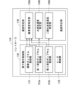
- FIG. FIG. 1 is a block diagram showing functional components implemented in a controller 110.
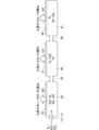
- 1 is a schematic diagram showing basic gas inflow and outflow patterns in three chambers provided in a sensor element 101 of a gas sensor 100.
- FIG. 10A and 10B are diagrams for explaining problems that occur when the gas sensor 100 continuously performs measurements based on the basic operation.
- 10A and 10B are diagrams for explaining problems that occur when the gas sensor 100 continuously performs measurements based on the basic operation.
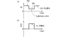
- FIG. 13 is a diagram showing changes over time in target values of electromotive forces V0, V1, and V2 during the generated gas discharge operation.
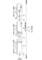
- 10 is a schematic diagram showing how gas flows in and out of three chambers during a generated gas discharge operation.
- FIG. FIG. 11 is a diagram showing yet another example of the generated gas discharge operation.
- FIG. 1 is a diagram showing an example of the configuration of a gas sensor 100 according to the present embodiment.
- the gas sensor 100 is a multi-gas sensor that detects a plurality of types of gas components using a sensor element 101 and measures their concentrations. In the present embodiment, it is assumed that at least water vapor (H 2 O) and carbon dioxide (CO 2 ) are the main gas components to be detected by the gas sensor 100.
- the gas sensor 100 is attached to an exhaust path of an internal combustion engine such as an automobile engine, and is used in a mode in which the exhaust gas flowing through the exhaust path is the measured gas.
- FIG. 1 includes a vertical cross-sectional view along the longitudinal direction of the sensor element 101.
- the sensor element 101 has a long plate-shaped structure (base portion) 14 made of an oxygen ion conductive solid electrolyte, a first diffusion rate-controlling portion 11 formed at one end (left end in the drawing) of the structure 14 and also serving as a gas inlet 10 through which the gas to be measured is introduced, and a buffer space 12, a first chamber 20, a second chamber 40, and a third chamber 61 formed within the structure 14 and sequentially communicating with the gas inlet 10 (first diffusion rate-controlling portion 11).
- the buffer space 12 communicates with the gas inlet 10 (first diffusion rate-controlling portion 11).
- the first chamber 20 communicates with the buffer space 12 via the second diffusion rate-controlling portion 13.
- the second chamber 40 communicates with the first chamber 20 via the third diffusion rate-controlling portion 30.
- the third chamber 61 communicates with the second chamber 40 via the fourth diffusion rate-controlling portion 60.
- the structure 14 is formed by stacking multiple layers of substrates made of, for example, ceramics. Specifically, the structure 14 has a configuration in which six layers, including a first substrate 1, a second substrate 2, a third substrate 3, a first solid electrolyte layer 4, a spacer layer 5, and a second solid electrolyte layer 6, are stacked in this order from the bottom up. Each layer is formed of an oxygen ion conductive solid electrolyte such as zirconia (ZrO 2 ).
- ZrO 2 zirconia
- the first diffusion rate-controlling section 11, which also serves as the gas inlet 10, the buffer space 12, the second diffusion rate-controlling section 13, the first chamber 20, the third diffusion rate-controlling section 30, the second chamber 40, the fourth diffusion rate-controlling section 60, and the third chamber 61 are formed in this order on one end side of the structure 14 between the lower surface 6b of the second solid electrolyte layer 6 and the upper surface 4a of the first solid electrolyte layer 4.
- the portion from the gas inlet 10 to the third chamber 61 is also referred to as the gas flow section.
- the buffer space 12, the first chamber 20, the second chamber 40, and the third chamber 61 are formed so as to penetrate the spacer layer 5 in the thickness direction. At the top of these chambers, the lower surface 6b of the second solid electrolyte layer 6 is exposed, and at the bottom of the drawing, the upper surface 4a of the first solid electrolyte layer 4 is exposed.
- the sides of these chambers are partitioned by the spacer layer 5 or any of the diffusion rate-controlling parts.
- the length (size in the longitudinal direction of the element) of the first chamber 20, the second chamber 40, and the third chamber 61 is, for example, 0.3 mm to 1.0 mm
- the width (size in the lateral direction of the element) is, for example, 0.5 mm to 30 mm
- the height (size in the thickness direction of the element) is, for example, 50 ⁇ m to 200 ⁇ m.
- the sizes of the chambers do not need to be the same and may be different.
- the gas inlet 10 may be formed separately from the first diffusion rate-controlling section 11 so as to penetrate the spacer layer 5 in the thickness direction.
- the first diffusion rate-controlling section 11 is formed adjacent to and inside the gas inlet 10.
- the first diffusion rate-controlling section 11, the second diffusion rate-controlling section 13, the third diffusion rate-controlling section 30, and the fourth diffusion rate-controlling section 60 each have two horizontally long slits. That is, they have openings at the top and bottom as viewed in the drawing that extend long in a direction perpendicular to the drawing.
- the length of the slits (size in the longitudinal direction of the element) is, for example, 0.2 mm to 1.0 mm
- the width of the opening (size in the transverse direction of the element) is, for example, 0.5 mm to 30 mm
- the height of the opening (size in the thickness direction of the element) is, for example, 5 ⁇ m to 30 ⁇ m.
- a reference gas introduction space 43 is provided at the other end (the right end as viewed in the drawing) of the sensor element 101 opposite to the end where the gas introduction port 10 is provided.
- the reference gas introduction space 43 is formed between the upper surface 3a of the third substrate 3 and the lower surface 5b of the spacer layer 5.
- the side of the reference gas introduction space 43 is partitioned by the side surface of the first solid electrolyte layer 4.
- oxygen ( O2 ) or air is introduced as a reference gas.
- the gas inlet 10 (first diffusion rate limiting section 11) is a section that opens to the external space, and the gas to be measured is taken into the sensor element 101 from the external space through the gas inlet 10.
- the first diffusion rate-controlling section 11 is a section that provides a predetermined diffusion resistance to the taken-in measurement gas.
- the buffer space 12 is provided to counteract the concentration fluctuations of the measured gas caused by pressure fluctuations of the measured gas in the external space.
- An example of such pressure fluctuations of the measured gas is the pulsation of the exhaust pressure of automobile exhaust gas.
- the second diffusion rate-controlling section 13 is a section that imparts a predetermined diffusion resistance to the measurement gas that is introduced from the buffer space 12 into the first chamber 20.
- the first chamber 20 is provided as a space for pumping out oxygen from the measurement gas introduced through the second diffusion rate-controlling part 13, and further for reducing (decomposing) H 2 O and CO 2 to generate hydrogen (H 2 ) and carbon monoxide (CO) in association with the pumping, so that the measurement gas does not substantially contain oxygen, H 2 O, and CO 2.
- the pumping out of oxygen is achieved by the operation of the adjustment pump cell 21.
- the adjustment pump cell 21 is an electrochemical pump cell composed of an inner pump electrode (adjustment electrode) 22, an outer pump electrode (outside the cavity pump electrode) 23, and a solid electrolyte present in the portion of the structure 14 sandwiched between the two electrodes.
- a voltage Vp0 is applied between the inner pump electrode 22 and the outer pump electrode 23 by a variable power supply 24 provided outside the sensor element 101, generating an oxygen pump current (oxygen ion current) Ip0.
- This makes it possible to pump oxygen from the first chamber 20 to the external space.
- the direction of the oxygen pump current Ip0 when oxygen is pumped out of the first chamber 20 is set to the positive direction of the oxygen pump current Ip0.
- the inner pump electrode 22 is provided as a ceiling electrode portion 22a and a bottom electrode portion 22b on substantially the entire surface of the lower surface 6b of the second solid electrolyte layer 6 that defines the first chamber 20 and substantially the entire surface of the upper surface 4a of the first solid electrolyte layer 4, respectively.
- the ceiling electrode portion 22a and the bottom electrode portion 22b are connected by a conductive portion (not shown).
- the inner pump electrode 22 is provided as a porous cermet electrode that is rectangular in plan view and contains at least one of platinum and rhodium (Rh) as a metal component.
- the outer pump electrode 23 is provided as a porous cermet electrode having a rectangular shape in plan view, containing platinum or an alloy of platinum and gold (Pt-Au alloy) as the metal component, for example, platinum or a Pt-Au alloy and zirconia.
- the first vacant chamber sensor cell 80 is composed of the inner pump electrode 22, the reference electrode 42, and a solid electrolyte present in the portion of the structure 14 sandwiched between the two electrodes.
- the first vacant chamber sensor cell 80 is an electrochemical sensor cell for determining the oxygen partial pressure in the atmosphere in the first vacant chamber 20.
- the reference electrode 42 is an electrode formed between the first solid electrolyte layer 4 and the third substrate 3, and is provided, for example, as a porous cermet electrode that contains platinum and zirconia and has a rectangular shape in a plan view.
- a reference gas introduction layer 48 made of porous alumina and connected to the reference gas introduction space 43 is provided around the reference electrode 42.
- the reference gas in the reference gas introduction space 43 is introduced to the surface of the reference electrode 42 through the reference gas introduction layer 48. In other words, the reference electrode 42 is always in contact with the reference gas.
- an electromotive force (Nernst electromotive force) V0 is generated between the inner pump electrode 22 and the reference electrode 42.
- the electromotive force V0 has a value that corresponds to the difference between the oxygen concentration (oxygen partial pressure) in the first chamber 20 and the oxygen concentration (oxygen partial pressure) of the reference gas.
- the electromotive force V0 has a value that corresponds to the oxygen concentration (oxygen partial pressure) in the first chamber 20.
- the third diffusion rate-controlling portion 30 is a portion that imparts a predetermined diffusion resistance to the measurement gas that is introduced from the first chamber 20 to the second chamber 40 and that substantially does not contain oxygen, H 2 O, or CO 2 .
- the second chamber 40 is provided as a space for selectively oxidizing all of H2 out of H2 and CO contained in the measurement gas introduced through the third diffusion-controlling part 30 to generate H2O again.
- the generation of H2O by the oxidation of H2 is realized by the operation of the first measuring pump cell 50.
- the first measurement pump cell 50 is an electrochemical pump cell composed of a first measurement electrode 51, an outer pump electrode 23, and a solid electrolyte present in the portion of the structure 14 sandwiched between the two electrodes.
- a voltage Vp1 is applied between the first measurement electrode 51 and the outer pump electrode 23 by a variable power supply 52 provided outside the sensor element 101, generating an oxygen pump current (oxygen ion current) Ip1.
- oxygen pump current oxygen ion current
- the direction of the oxygen pump current Ip1 when oxygen is pumped out of the second chamber 40 is set to the positive direction of the oxygen pump current Ip1.
- the first measurement electrode 51 is provided as a ceiling electrode portion 51a and a bottom electrode portion 51b on substantially the entire surface of the lower surface 6b of the second solid electrolyte layer 6 that defines the second chamber 40 and substantially the entire surface of the upper surface 4a of the first solid electrolyte layer 4.
- the ceiling electrode portion 51a and the bottom electrode portion 51b are connected by a conductive portion (not shown).
- the first measurement electrode 51 is provided as a porous cermet electrode containing a Pt-Au alloy as a metal component, for example, the Pt-Au alloy and zirconia, and having a rectangular shape in plan view.
- the Au concentration in the Pt-Au alloy is preferably 1 wt% or more and 50 wt% or less, and more preferably 10 wt% or more and 30 wt% or less.
- the selective oxidation of H 2 at the first measurement electrode 51 that is, the property that when H 2 and CO coexist in the second chamber 40, only H 2 is selectively oxidized by oxygen pumped in by the first measurement pump cell 50, and CO is not oxidized, is more suitably expressed.
- the second vacant chamber sensor cell 81 is composed of the first measurement electrode 51, the reference electrode 42, and a solid electrolyte present in the portion of the structure 14 sandwiched between the two electrodes.
- the second vacant chamber sensor cell 81 is an electrochemical sensor cell for determining the oxygen partial pressure in the atmosphere in the second vacant chamber 40.
- an electromotive force (Nernst electromotive force) V1 is generated between the first measurement electrode 51 and the reference electrode 42.
- the electromotive force V1 has a value that corresponds to the difference between the oxygen concentration (oxygen partial pressure) in the second chamber 40 and the oxygen concentration (oxygen partial pressure) of the reference gas.
- the electromotive force V1 has a value that corresponds to the oxygen concentration (oxygen partial pressure) in the second chamber 40.
- the fourth diffusion rate-controlling portion 60 is a portion that provides a predetermined diffusion resistance to the measurement gas that is introduced from the second chamber 40 to the third chamber 61 and contains H 2 O and CO but substantially no CO 2 or oxygen.
- the third chamber 61 is provided as a space for oxidizing all of the CO contained in the measurement gas introduced through the fourth diffusion-controlling part 60 to generate CO2 again.
- the generation of CO2 by the oxidation of CO is realized by the operation of the second measuring pump cell 41.
- the second measurement pump cell 41 is an electrochemical pump cell composed of a second measurement electrode 44, an outer pump electrode 23, and a solid electrolyte present in the portion of the structure 14 sandwiched between the two electrodes.
- a voltage Vp2 is applied between the second measurement electrode 44 and the outer pump electrode 23 by a variable power supply 46 provided outside the sensor element 101, generating an oxygen pump current (oxygen ion current) Ip2.
- oxygen pump current oxygen ion current
- the direction of the oxygen pump current Ip2 when oxygen is pumped out of the third chamber 61 is set to the positive direction of the oxygen pump current Ip2.
- the second measurement electrode 44 is provided on substantially the entire upper surface 4a of the first solid electrolyte layer 4 that defines the third chamber 61.
- the second measurement electrode 44 is provided as a porous cermet electrode having a rectangular shape in a plan view, for example, containing Pt and zirconia as the metal component.
- the third vacant chamber sensor cell 82 is composed of the second measurement electrode 44, the reference electrode 42, and a solid electrolyte present in the portion of the structure 14 sandwiched between the two electrodes.
- the third vacant chamber sensor cell 82 is an electrochemical sensor cell for determining the oxygen partial pressure in the atmosphere in the third vacant chamber 61.
- an electromotive force (Nernst electromotive force) V2 is generated between the second measurement electrode 44 and the reference electrode 42.
- the electromotive force V2 has a value that corresponds to the difference between the oxygen concentration (oxygen partial pressure) in the third chamber 61 and the oxygen concentration (oxygen partial pressure) of the reference gas.
- the electromotive force V2 has a value that corresponds to the oxygen concentration (oxygen partial pressure) in the third chamber 61.
- the sensor element 101 further includes an electrochemical sensor cell 83 that is composed of an outer pump electrode 23, a reference electrode 42, and a solid electrolyte that is present in the portion of the structure 14 that is sandwiched between the two electrodes.
- the electromotive force Vref that is generated between the outer pump electrode 23 and the reference electrode 42 in the sensor cell 83 has a value that corresponds to the oxygen partial pressure of the measured gas that is present outside the sensor element 101.
- the sensor element 101 is equipped with a heater section 70 that serves to adjust the temperature by heating and keeping the sensor element 101 warm in order to increase the oxygen ion conductivity of the solid electrolyte that constitutes the structure 14.
- the heater section 70 mainly comprises a heater electrode 71, a heater element 72, a heater lead 72a, a through hole 73, a heater insulating layer 74, and a heater resistance detection lead (not shown in FIG. 1).
- the heater element 72 will also be referred to simply as the heater 72.
- the heater 72 is sandwiched between the second substrate 2 and the third substrate 3 from above and below, and generates heat when power is supplied from the outside through the heater electrode 71, through hole 73, and heater lead 72a provided on the underside 1b of the first substrate 1.
- the heater 72 is embedded throughout the entire range from the buffer space 12 to the third chamber 61, and is capable of heating the sensor element 101 to a predetermined temperature and keeping it warm.
- the heater 72 is arranged so that when heated, the temperature is highest near the first chamber 20 (near the adjustment electrode 22) and decreases the further away from the first chamber 20 in the element longitudinal direction.
- the temperature in the range from one end of the sensor element 101 equipped with the gas inlet 10 to the third chamber 61 when the gas sensor 100 is used (when the sensor element 101 is driven) is referred to as the element drive temperature.
- the heater 72 heats so that the element drive temperature is within the range of 750°C to 950°C.
- Heater insulating layers 74 made of alumina or the like are formed above and below the heater 72 in order to provide electrical insulation between the second substrate 2 and the third substrate 3.
- the heater section 70 also has a pressure release hole 75.
- the pressure release hole 75 is a portion that penetrates the third substrate 3 and is provided so as to communicate with the reference gas introduction space 43, and is provided for the purpose of mitigating the increase in internal pressure that accompanies a rise in temperature within the heater insulating layer 74.
- the gas sensor 100 also includes a controller 110 that controls the operation of the sensor element 101 and is responsible for determining the concentration of the gas component to be detected based on the current flowing through the sensor element 101.
- FIG. 2 is a block diagram showing the functional components realized in the controller 110.
- the controller 110 is composed of one or more electronic circuits having, for example, one or more CPUs (Central Processing Units) and a storage device.
- the electronic circuit is also a software function unit in which specific functional components are realized by, for example, the CPU executing a specific program stored in the storage device.
- it may also be composed of an integrated circuit such as an FPGA (Field-Programmable Gate Array) in which multiple electronic circuits are connected according to their functions.
- FPGA Field-Programmable Gate Array
- the gas sensor 100 When the gas sensor 100 is attached to the exhaust path of an automobile engine and the exhaust gas flowing through the exhaust path is used as the gas to be measured, some or all of the functions of the controller 110 may be realized by the automobile's ECU (electronic control unit).
- ECU electronic control unit
- the controller 110 includes, as functional components realized by the execution of a specific program in the CPU, an element operation control unit 120 that controls the operation of each part of the sensor element 101 described above, and a concentration determination unit 130 that is responsible for the process of determining the concentration of the target gas component contained in the measured gas.
- the element operation control unit 120 mainly comprises an adjustment pump cell control unit 121 that controls the operation of the adjustment pump cell 21, a first measurement pump cell control unit 122a that controls the operation of the first measurement pump cell 50, a second measurement pump cell control unit 122b that controls the operation of the second measurement pump cell 41, and a heater control unit 123 that controls the heating operation by the heater 72.
- the concentration specifying unit 130 mainly includes a water vapor concentration specifying unit 130H and a carbon dioxide concentration specifying unit 130C that respectively specify the concentrations of H 2 O and CO 2 , which are the main detection target gas components in the gas sensor 100 .
- the water vapor concentration specifying unit 130H specifies the concentration of H 2 O contained in the measurement target gas based on the value of the oxygen pump current Ip1 flowing through the first measurement pump cell 50, which is acquired by the first measurement pump cell control unit 122a.
- the carbon dioxide concentration specifying unit 130C specifies the concentration of CO2 contained in the measurement gas based on the value of the oxygen pump current Ip2 flowing through the second measurement pump cell 41, which is acquired by the second measurement pump cell control unit 122b.
- the concentration determination unit 130 further includes an oxygen concentration determination unit 130A that determines the concentration of oxygen contained in the measurement gas.
- the oxygen concentration determination unit 130A determines the concentration of oxygen contained in the measurement gas based on the value of the oxygen pump current Ip0 flowing through the adjustment pump cell 21 acquired by the adjustment pump cell control unit 121, the value of the oxygen pump current Ip1 flowing through the first measurement pump cell 50 acquired by the first measurement pump cell control unit 122a, and the value of the oxygen pump current Ip2 flowing through the second measurement pump cell 41 acquired by the second measurement pump cell control unit 122b. That is, in the gas sensor 100 according to the present embodiment, in addition to H 2 O and CO 2 , which are the main detection target gas components, oxygen is also detected as an incidental detection target gas component.
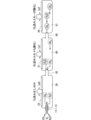
- Figure 3 is a schematic diagram showing the basic flow of gas in and out of the three chambers (internal spaces) in the sensor element 101 of the gas sensor 100.
- the measurement gas is introduced into the first chamber 20 through the gas inlet 10 (first diffusion rate-controlling portion 11), the buffer space 12, and the second diffusion rate-controlling portion 13.
- the adjustment pump cell 21 is operated to pump out oxygen contained in the measurement gas introduced therein and reduce H 2 O and CO 2.
- the adjustment pump cell 21 is operated to pump out oxygen from the measurement gas introduced into the first chamber 20, and the reduction (decomposition) reaction of H 2 O and CO 2 contained in the measurement gas (2H 2 O ⁇ 2H 2 +O 2 , 2CO 2 ⁇ 2CO+O 2 ) proceeds, and substantially all of H 2 O and CO 2 are decomposed into hydrogen (H 2 ), carbon monoxide (CO), and oxygen.
- the pumping of oxygen and the reduction (decomposition) of H2O and CO2 are carried out by the adjustment pump cell control section 121 of the controller 110 setting the target value (control voltage) of the electromotive force V0 in the first vacant room sensor cell 80 to a value within the range of 1000 mV to 1500 mV (preferably 1000 mV), and feedback-controlling the voltage Vp0 applied to the adjustment pump cell 21 by the variable power supply 24 in accordance with the difference between the actual value of the electromotive force V0 and the target value so that the electromotive force V0 is maintained at the target value.
- the oxygen partial pressure in the first chamber 20 is kept at a sufficiently low value that it is considered that substantially no oxygen is present.
- the measurement gas does not substantially contain H 2 O, CO 2 , or oxygen.
- a measurement gas containing H 2 and CO but substantially free of H 2 O, CO 2 and oxygen is introduced into the second chamber 40 .
- oxygen is pumped in by the operation of the first measuring pump cell 50, and only H2 contained in the introduced measurement gas is selectively oxidized.
- the pumping of oxygen is performed by the first measurement pump cell control unit 122a of the controller 110 setting the target value (control voltage) of the electromotive force V1 in the second vacant chamber sensor cell 81 to a value within the range of 250 mV to 450 mV (preferably 350 mV), and feedback-controlling the voltage Vp1 applied to the first measurement pump cell 50 by the variable power supply 52 according to the difference between the actual value of the electromotive force V1 and the target value so that the electromotive force V1 is maintained at the target value.
- the oxidation (combustion) reaction of 2H 2 +O 2 ⁇ 2H 2 O is promoted in the second chamber 40, and an amount of H 2 O that is correlated with the amount of H 2 O introduced from the gas inlet 10 is generated again.
- the correlation of the amount of H 2 O means that the amount of H 2 O introduced from the gas inlet 10 and the amount of H 2 O generated again by oxidizing the H 2 generated by the decomposition of H 2 O are the same or within a certain error range that is allowable from the viewpoint of measurement accuracy.
- the oxygen partial pressure in the second chamber 40 is maintained within a range in which H2 is almost entirely oxidized but CO is not oxidized.
- providing the first measurement electrode 51 as a cermet electrode containing a Pt-Au alloy having an Au concentration of 1 wt % or more and 50 wt % or less as a metal component also contributes to improving the selective oxidation of H 2 .
- the oxygen pump current Ip1 (hereinafter also referred to as the water vapor detection current Ip1) flowing through the first measurement pump cell 50 is approximately proportional to the concentration of H2O generated by the combustion of H2 in the second chamber 40 (the water vapor detection current Ip1 and the concentration of the generated H2O are in a linear relationship).
- the amount of H2O generated by such combustion correlates with the amount of H2O in the measurement gas that is introduced from the gas inlet 10 and then decomposed in the first chamber 20. Therefore, when the water vapor detection current Ip1 is detected in the first measurement pump cell control unit 122a, H2O in the measurement gas is detected. Therefore, the second chamber 40 is also referred to as the first measurement chamber.
- a linear relationship is established between the water vapor detection current Ip1 and the water vapor concentration in the measured gas.
- Data water vapor characteristic data showing this linear relationship is determined in advance using a model gas with a known water vapor concentration, and is stored in the water vapor concentration determination unit 130H.
- the water vapor concentration determination unit 130H acquires the value of the water vapor detection current Ip1 detected in the first measurement pump cell control unit 122a.
- the water vapor concentration determination unit 130H refers to the water vapor characteristic data and identifies the value of the water vapor concentration corresponding to the acquired water vapor detection current Ip1. This identifies the water vapor concentration in the measured gas.
- H2O is not present in the measurement gas introduced through the gas inlet 10, naturally, decomposition of H2O will not occur in the first chamber 20, and therefore no H2 will be introduced into the second chamber 40, and the water vapor detection current Ip1 will be approximately zero.
- the measurement gas contains H2O and CO and is substantially free of CO2 and oxygen.
- the measurement gas is introduced into the third chamber 61.
- the second measurement pump cell 41 is operated to pump in oxygen, and the CO contained in the introduced measurement gas is oxidized.
- the pumping of oxygen is performed by the second measurement pump cell control section 122b of the controller 110 setting the target value (control voltage) of the electromotive force V2 in the third vacant chamber sensor cell 82 to a value within the range of 100 mV to 300 mV (preferably 200 mV), and feedback-controlling the voltage Vp2 applied by the variable power supply 46 to the second measurement pump cell 41 in accordance with the difference between the actual value of the electromotive force V2 and the target value so that the electromotive force V2 is maintained at the target value.
- the oxidation (combustion) reaction 2CO + O2 ⁇ 2CO2 is promoted in the third chamber 61, and an amount of CO2 that is correlated with the amount of CO2 introduced from the gas inlet 10 is again generated.
- the oxygen pump current Ip2 (hereinafter also referred to as the carbon dioxide detection current Ip2) flowing through the second measurement pump cell 41 is approximately proportional to the concentration of CO2 generated by the combustion of CO in the third chamber 61 (the carbon dioxide detection current Ip2 and the concentration of the generated CO2 are in a linear relationship).
- the amount of CO2 generated by such combustion correlates with the amount of CO2 in the measurement gas that is introduced from the gas inlet 10 and then decomposed in the first chamber 20. Therefore, when the carbon dioxide detection current Ip2 is detected in the second measurement pump cell control unit 122b, CO2 in the measurement gas is detected. Therefore, the third chamber 61 is also referred to as the second measurement chamber.
- a linear relationship is established between the carbon dioxide detection current Ip2 and the carbon dioxide concentration in the measured gas.
- Data carbon dioxide characteristic data showing this linear relationship is determined in advance using a model gas with a known carbon dioxide concentration, and is stored in the carbon dioxide concentration determination unit 130C.
- the carbon dioxide concentration determination unit 130C acquires the value of the carbon dioxide detection current Ip2 detected in the second measurement pump cell control unit 122b.
- the carbon dioxide concentration determination unit 130C refers to the carbon dioxide characteristic data and identifies the value of the carbon dioxide concentration corresponding to the acquired carbon dioxide detection current Ip2. This identifies the carbon dioxide concentration in the measured gas.
- the operating mode of the gas sensor 100 as described above with reference to FIG. 3 will also be referred to as the basic operation.
- the gas sensor 100 is also capable of indirectly determining the concentration of oxygen contained in the measurement gas.
- C0, C1, and C2 are values approximately proportional to the oxygen pump currents Ip0, Ip1, and Ip2, respectively, and in the gas sensor 100, the relationships (proportionality constants) between C0 and Ip0, C1 and Ip1, and C2 and Ip2 are specified in advance and stored in the oxygen concentration specifying unit 130A.
- the oxygen concentration specifying unit 130A obtains the detection values of the oxygen pump currents Ip0, Ip1, and Ip2 from the adjustment pump cell control unit 121, the first measurement pump cell control unit 122a, and the second measurement pump cell control unit 122b, respectively, and calculates the concentration of oxygen in the measurement gas based on these detection values, the proportionality constants, and formula (1).
- ⁇ Specifying concentrations taking into consideration continuous use> 4 and 5 are diagrams for explaining problems that may occur when the gas sensor 100 continuously performs measurements based on the above-described basic operation.
- the H 2 O generated in the second chamber 40 is basically introduced into the third chamber 61 or remains in the second chamber 40.
- the CO 2 generated in the third chamber 61 basically remains in the third chamber 61. Therefore, as the measurement is continuously performed, the amounts of H 2 O and CO 2 generated in the second chamber 40 and the third chamber 61 increase.
- H 2 O and CO 2 present in the third chamber 61 or the second chamber 40 may diffuse from the third chamber 61 and the second chamber 40 to the first chamber 20. In other words, a backflow of H 2 O and CO 2 into the first chamber 20 may occur.
- the adjustment pump cell 21 is operated to continuously pump out oxygen and reduce H 2 O and CO 2. Therefore, as shown in Fig. 5, when H 2 O and CO 2 flow back from the third chamber 61 and the second chamber 40, they are (re)reduced to H 2 and CO without being distinguished from the H 2 O and CO 2 contained in the measurement gas introduced from the gas inlet 10 and which are the original measurement targets at that time.
- the H2 oxidized by the first measuring pump cell 50 pumping oxygen into the second chamber 40 contains H2 produced by the re-reduction
- the CO oxidized by the second measuring pump cell 41 pumping oxygen into the third chamber 61 contains CO produced by the re-reduction, so that the water vapor detection current Ip1 flowing through the first measuring pump cell 50 and the carbon dioxide detection current Ip2 flowing through the second measuring pump cell 41 are superimposed with currents derived from the re-reduced H2O and CO2 . That is, the values of the water vapor detection current Ip1 and the carbon dioxide detection current Ip2 no longer correspond to the concentrations of H2O and CO2 inherently contained in the measured gas, resulting in a decrease in measurement accuracy.
- the operation of each pump cell is controlled so as to prevent a decrease in measurement accuracy due to the backflow of H 2 O and CO 2.
- the measurement accuracy is ensured by performing an operation to discharge H 2 O and CO 2 that have flowed back to the first chamber 20 to the outside of the sensor element 101, rather than suppressing the backflow of H 2 O and CO 2 generated in the second chamber 40 and the third chamber 61.
- This operation mode is also referred to as a generated gas discharge operation.
- Figure 6 shows the time change in the target values of electromotive forces V0, V1, and V2 during the generated gas discharge operation.
- Figure 7 is a schematic diagram showing the flow of gas in and out of the three voids (internal spaces) during the generated gas discharge operation.
- the target value of the electromotive force V0 in the first vacant chamber sensor cell 80 is set to a value within the range of 1000 mV to 1500 mV, and the voltage Vp0 applied to the adjustment pump cell 21 is feedback controlled so that the electromotive force V0 is maintained at this target value.
- the target value (set value) of the electromotive force V0 in the first vacant chamber sensor cell 80 is temporarily changed from a steady value of V0a to a value of V0b at an appropriate timing.
- the value V0a is a value in the range of 1000 mV to 1500 mV, similar to the target value of the electromotive force V0 in basic operation.
- the value V0a may be set to the same value as the target value of the electromotive force V0 during basic operation.
- the adjustment pump cell 21 pumps oxygen from the first chamber 20 to the outside so that substantially all of the H 2 O and CO 2 contained in the measured gas are reduced, just as in basic operation.
- value V0b is smaller than value V0a and is within the range of 400 mV to 700 mV (preferably 400 mV).
- the adjustment pump cell 21 performs a pumping operation (second pumping operation) to pump oxygen from the first chamber 20 to the extent that the water vapor and carbon dioxide contained in the measured gas introduced into the first chamber 20 are not reduced, during the pumping operation (first pumping operation) to pump oxygen from the first chamber 20 so that substantially all of the water vapor and carbon dioxide contained in the measured gas are reduced.
- the target values of electromotive force V1 and electromotive force V2 are set in the same way as in the basic operation. Specifically, the target value of electromotive force V1 is set to a value within the range of 250 mV to 450 mV (preferably 350 mV), and the target value of electromotive force V2 is set to a value within the range of 100 mV to 300 mV (preferably 200 mV).
- the operation of the gas sensor 100 while the target value of the electromotive force V0 is set to the value V0a is the same as that of the basic operation, but when the target value of the electromotive force V0 is set to the value V0b, only the pumping out of the oxygen contained in the introduced measurement gas is performed in the first chamber 20, and H 2 O and CO 2 are not reduced. Therefore, as a result of the accumulation of H 2 O and CO 2 generated in the second chamber 40 and the third chamber 61, a concentration gradient as shown in FIG. 4 is generated, and even if H 2 O and CO 2 flow back into the first chamber 20, the backflowing H 2 O and CO 2 are discharged to the outside of the element as they are without being reduced again in the first chamber 20, as shown in FIG. 7.
- the second pumping operation may be performed at any timing, or at a predetermined timing. Alternatively, the second pumping operation may be performed when a predetermined condition is satisfied. For example, the longer the measured values of H 2 O and CO 2 in the gas sensor 100 remain large, the larger the amounts of H 2 O and CO 2 generated in the second chamber 40 and the third chamber 61 become. Therefore, the second pumping operation may be performed based on the integral value of the measured values.
- the time when the target value of the electromotive force V0 is set to the value V0b and the second pumping operation is performed is preferably within the range of 1 ms to 1 s. If the set time is shorter than 1 ms, the diffusion of H 2 O and CO 2 from the second chamber 40 or the third chamber 61 does not proceed sufficiently, so that the concentration gradient is not weakened sufficiently and the measurement accuracy may continue to decrease, which is not preferable. If the set time is longer than 1 s, the time when the H 2 O and CO 2 contained in the newly introduced measurement gas cannot be reduced becomes longer, that is, the time when the concentration measurement cannot be performed becomes longer, which is not preferable, so that the responsiveness decreases.
- the target value of the electromotive force V0 may be periodically changed and the first pumping operation and the second pumping operation may be alternately and periodically performed in the adjustment pump cell 21 to temporarily stop the reduction of H2O and CO2 periodically, and the target values (set values) of the electromotive force V1 in the second vacant room sensor cell 81 and the electromotive force V2 in the third vacant room sensor cell 82 may also be periodically changed in a manner synchronized with the periodic change in the target value of the electromotive force V0, as shown in Fig. 6(b).
- the pumping of oxygen by the first measurement pump cell 50 and the second measurement pump cell 41 may be synchronized with the second pumping operation.
- the target values of electromotive force V1 and electromotive force V2 are set to 0 while the target value of electromotive force V0 is set to value V0a, and are set to values within the same range as in basic operation only while the target value of electromotive force V0 is set to value V0b.
- the first measuring pump cell 50 and the second measuring pump cell 41 operate only while the adjustment pump cell 21 is performing the second pumping operation, and do not operate while the adjustment pump cell 21 is performing the first pumping operation. Note that in FIG. 6(b), both are shown on a single graph for simplicity, but in reality, electromotive force V1 and electromotive force V2 are set to different values.
- the reduction of H2O and CO2 in the first chamber 20 and the selective oxidation of H2 and CO in the second chamber 40 and the third chamber 61 are performed at different times. That is, while H2 and CO are reoxidized in the second chamber 40 and the third chamber 61, only the pumping out of the oxygen contained in the introduced measurement gas is performed in the first chamber 20, and H2O and CO2 are not reduced. In this case, even if the H2O and CO2 generated in the second chamber 40 and the third chamber 61 are retained and a concentration gradient as shown in FIG. 4 occurs, the H2O and CO2 that flow back to the first chamber 20 are discharged to the outside of the element as they are without being re-reduced in the first chamber 20.
- the time during which the target value of the electromotive force V0 is set to the value V0a is also within the range of 1 ms to 1 s.
- FIG. 8 is a diagram showing yet another example of the generated gas discharge operation.
- the periodic change in the target value of the electromotive force V0 is the same as in FIG. 6(a), but as shown in FIG. 8(b), the phase (timing) of the periodic change in the target values of the electromotive forces V1 and V2 is shifted from that shown in FIG. 6(b).
- the start of pumping oxygen into the second chamber 40 and the third chamber 61 is advanced to the middle of the first pumping operation, and the pumping is terminated in the middle of the second pumping operation.
- the degree to which the start time is advanced is set to 50% or less of the time ⁇ t during which the first pumping operation is being performed (the time during which the target value of the electromotive force V0 is set to the value V0a).
- a gas sensor that pumps out oxygen contained in a measurement gas and reduces H 2 O and CO 2 in the first chamber, oxidizes H 2 and CO generated by the reduction in the second and third chambers, respectively, and determines the concentrations of H 2 O and CO 2 contained in the measurement gas based on the magnitude of the oxygen pump current pumped into the second and third chambers during the oxidation, the reduction of H 2 O and CO 2 in the first chamber is temporarily or periodically stopped, and H 2 O and CO 2 generated by the oxidation of H 2 and CO are discharged from the first chamber to the outside of the sensor element using their concentration gradient.
- the gas sensor 100 including the three-chamber sensor element 101 is targeted for discharging the H2O and CO2 produced by oxidizing the H2O and CO2 produced by the reduction of the H2O and CO2 contained in the measurement gas for concentration measurement.
- the process of reducing the H2O and CO2 contained in the measurement gas to produce H2 and CO is performed in only one empty chamber.
- the sensor element may have another structure.
Landscapes
- Chemical & Material Sciences (AREA)
- Health & Medical Sciences (AREA)
- Life Sciences & Earth Sciences (AREA)
- Analytical Chemistry (AREA)
- Physics & Mathematics (AREA)
- Electrochemistry (AREA)
- Chemical Kinetics & Catalysis (AREA)
- Biochemistry (AREA)
- General Health & Medical Sciences (AREA)
- General Physics & Mathematics (AREA)
- Immunology (AREA)
- Pathology (AREA)
- Molecular Biology (AREA)
- Measuring Oxygen Concentration In Cells (AREA)
Abstract
Description
図1は、本実施の形態に係るガスセンサ100の構成の一例を概略的に示す図である。ガスセンサ100は、センサ素子101によって複数種類のガス成分を検知し、その濃度を測定するマルチガスセンサである。本実施の形態においては、少なくとも水蒸気(H2O)および二酸化炭素(CO2)が、ガスセンサ100における主たる検知対象ガス成分であるとする。ガスセンサ100は、例えば、自動車のエンジンなどの内燃機関の排気経路に取り付けられ、係る排気経路を流れる排ガスを被測定ガスとする態様にて使用される。図1は、センサ素子101の長手方向に沿った垂直断面図を含んでいる。
次に、上述のような構成を有するガスセンサ100において実現される、複数のガス種の検知(マルチガス検知)と、検知されたガスの濃度の特定における基本的考え方について説明する。以降においては、被測定ガスが酸素、H2O、およびCO2を含む排ガスであるとする。
C=C0-C1-C2 ・・・・(1)
が、ガス導入口10から導入された被測定ガス中の酸素の濃度に相当する。C0、C1、C2はそれぞれ、酸素ポンプ電流Ip0、Ip1、Ip2に略比例する値であり、ガスセンサ100においては、C0とIp0、C1とIp1、C2とIp2との関係(比例定数)が、あらかじめ特定されて酸素濃度特定部130Aに記憶されている。被測定ガスの測定が開始されると、酸素濃度特定部130Aは、調整ポンプセル制御部121、第1測定ポンプセル制御部122a、および第2測定ポンプセル制御部122bからそれぞれ、酸素ポンプ電流Ip0、Ip1、Ip2の検出値を取得し、これらの検出値と、上記の比例定数と、(1)式とに基づいて、被測定ガス中の酸素の濃度を求めるようになっている。
図4および図5は、ガスセンサ100が上述した基本動作に基づく測定を継続的に行った場合に生じる不具合について説明するための図である。
上述の実施の形態においては、3室構造のセンサ素子101を備えるガスセンサ100における、被測定ガスに含まれるH2OおよびCO2が還元されることにより生じたH2とCOとを、濃度測定のために酸化させることで生成されたH2OおよびCO2の生成ガス排出動作が、対象となっている。しかしながら、被測定ガスに含まれるH2OおよびCO2が還元されてH2とCOとが生成されるまでの過程が、1つの空室のみで行われることは、必須の態様ではない。上述の実施の形態と同様の生成ガス排出動作が可能であるならば、センサ素子が他の構造を有する態様であってもよい。
Claims (12)
- 少なくとも水蒸気と二酸化炭素とを含む被測定ガスに含まれる、複数の検知対象ガス成分の濃度を測定可能なガスセンサであって、
酸素イオン伝導性の固体電解質にて構成された構造体を有するセンサ素子と、
前記ガスセンサの動作を制御するコントローラと、
を備え、
前記センサ素子が、
前記被測定ガスが導入されるガス導入口と、
相異なる拡散律速部を介して前記ガス導入口から順次に連通してなる複数の空室と、
前記センサ素子を加熱するヒータと、
を備え、
前記複数の空室のうちの2つが第1測定用空室と第2測定用空室であり、前記第2測定用空室は前記複数の空室のうち前記ガス導入口から最奥の空室であり、前記第1測定用空室は前記第2測定用空室の1つ手前の空室であり、
前記ガス導入口から導入された前記被測定ガスが前記第1測定用空室に到達するまでの間に、前記被測定ガスに含まれる水蒸気および二酸化炭素が実質的に全て還元されるように前記被測定ガスに含まれる酸素を汲み出す第1の汲み出し動作を実行することが可能な酸素汲み出し手段と、
前記第1測定用空室に面して形成された第1測定電極と、前記複数の空室以外の箇所に設けられてなる空所外ポンプ電極と、前記第1測定電極と前記空所外ポンプ電極との間に存在する前記固体電解質とから構成された第1測定ポンプセルと、
前記第2測定用空室に面して形成された第2測定電極と、前記空所外ポンプ電極と、前記第2測定電極と前記空所外ポンプ電極との間に存在する前記固体電解質とから構成された第2測定ポンプセルと、
をさらに備え、
前記第1測定ポンプセルは、前記第1測定用空室に酸素を汲み入れることによって、前記第1測定用空室へと導入された前記被測定ガスに含まれている、前記第1の汲み出し動作に伴う水蒸気の還元によって生成した水素を、前記第1測定用空室において選択的に酸化することが可能に構成されてなり、
前記第2測定ポンプセルは、前記第2測定用空室に酸素を汲み入れることによって、前記第2測定用空室へと導入された前記被測定ガスに含まれている、前記第1の汲み出し動作に伴う二酸化炭素の還元によって生成した一酸化炭素を、前記第2測定用空室において酸化することが可能に構成されてなり、
前記コントローラは、
前記第1測定ポンプセルによって前記第1測定用空室に酸素を汲み入れる際に前記第1測定電極と前記空所外ポンプ電極との間を流れる電流の大きさに基づいて、前記被測定ガスに含まれる水蒸気の濃度を特定する水蒸気濃度特定手段と、
前記第2測定ポンプセルによって前記第2測定用空室に酸素を汲み入れる際に前記第2測定電極と前記空所外ポンプ電極との間を流れる電流の大きさに基づいて、前記被測定ガスに含まれる二酸化炭素の濃度を特定する二酸化炭素濃度特定手段と、
を備え、
前記酸素汲み出し手段はさらに、前記第1測定用空室に到達するまでの前記被測定ガスに含まれる水蒸気および二酸化炭素が還元されない範囲で前記被測定ガスに含まれる酸素を汲み出す第2の汲み出し動作を、前記第1の汲み出し動作の途中の所定時間、実行可能に構成されてなり、
前記第2の汲み出し動作が開始されて前記酸素汲み出し手段による水蒸気および二酸化炭素の還元が中断されることにより、前記第1測定用空室にて生成した水蒸気と前記第2測定用空室にて生成した二酸化炭素とが前記センサ素子の外部へと排出される、
ことを特徴とする、ガスセンサ。 - 請求項1に記載のガスセンサであって、
前記複数の空室が、第1空室、前記第1測定用空室である第2空室、および前記第2測定用空室である第3空室であり、
前記センサ素子が、
前記第1空室に面して形成された調整電極と、前記空所外ポンプ電極と、前記調整電極と前記空所外ポンプ電極との間に存在する前記固体電解質とから構成された、前記酸素汲み出し手段である調整ポンプセル、
をさらに備え、
前記調整ポンプセルは、前記第1の汲み出し動作として、前記第1空室に導入された前記被測定ガスに含まれる水蒸気および二酸化炭素が実質的に全て還元されるように前記第1空室から酸素を汲み出す動作を実行することが可能に構成されてなるとともに、前記第2の汲み出し動作として、前記第1空室に導入された前記被測定ガスに含まれる水蒸気および二酸化炭素が還元されない範囲で前記第1空室から酸素を汲み出す動作を、前記第1の汲み出し動作の途中の所定時間、実行可能に構成されてなり、
前記調整ポンプセルが前記第2の汲み出し動作を開始して前記第1空室における水蒸気および二酸化炭素の還元が中断されることにより、前記第2空室にて生成した水蒸気と前記第3空室にて生成した二酸化炭素とが前記第1空室を経て前記センサ素子の外部へと排出される、
ことを特徴とする、ガスセンサ。 - 請求項2に記載のガスセンサであって、
前記調整ポンプセルは、前記第1の汲み出し動作と前記第2の汲み出し動作とを交互にかつ周期的に行い、
前記第1測定ポンプセルによる前記第2空室への酸素の汲み入れと前記第2測定ポンプセルによる前記第3空室への酸素の汲み入れとが、前記調整ポンプセルによる前記第1の汲み出し動作と前記第2の汲み出し動作に応じて周期的に行われる、
ことを特徴とする、ガスセンサ。 - 請求項3に記載のガスセンサであって、
前記第1測定ポンプセルによる前記第2空室への酸素の汲み入れと前記第2測定ポンプセルによる前記第3空室への酸素の汲み入れとを、前記調整ポンプセルによる前記第2の汲み出し動作と同期させて行う、
ことを特徴とする、ガスセンサ。 - 請求項3に記載のガスセンサであって、
前記第1測定ポンプセルによる前記第2空室への酸素の汲み入れと前記第2測定ポンプセルによる前記第3空室への酸素の汲み入れとを、前記調整ポンプセルによる前記第1の汲み出し動作の途中から前記第2の汲み出し動作の途中まで行う、
ことを特徴とする、ガスセンサ。 - 請求項2ないし請求項5のいずれかに記載のガスセンサであって、
前記センサ素子が、
基準ガスと接触してなる基準電極と、
前記調整電極と、前記基準電極と、前記調整電極と前記基準電極との間に存在する前記固体電解質とから構成され、前記調整電極と前記基準電極との間に、前記第1空室の酸素濃度に応じた起電力V0が生じる第1空室用センサセルと、
前記第1測定電極と、前記基準電極と、前記第1測定電極と前記基準電極との間に存在する前記固体電解質とから構成され、前記第1測定電極と前記基準電極との間に、前記第2空室の酸素濃度に応じた起電力V1が生じる第2空室用センサセルと、
前記第2測定電極と、前記基準電極と、前記第2測定電極と前記基準電極との間に存在する前記固体電解質とから構成され、前記第2測定電極と前記基準電極との間に、前記第3空室の酸素濃度に応じた起電力V2が生じる第3空室用センサセルと、
をさらに備え、
前記コントローラが、
前記第1空室用センサセルにおける起電力V0が、前記第1の汲み出し動作の際には1000mV~1500mVなる範囲内の所定の目標値に保たれ、前記第2の汲み出し動作の際には400mV~700mVなる範囲内の所定の目標値に保たれるように、前記調整ポンプセルにおいて前記調整電極と前記空所外ポンプ電極との間に印加される電圧を制御する調整ポンプセル制御手段と、
前記第2空室用センサセルにおける起電力V1が、250mV~450mVなる範囲内の所定の目標値に保たれるように、前記第1測定ポンプセルにおいて前記第1測定電極と前記空所外ポンプ電極との間に印加される電圧を制御する第1測定ポンプセル制御手段と、
前記第3空室用センサセルにおける起電力V2が、100mV~300mVなる範囲内の所定の目標値に保たれるように、前記第2測定ポンプセルにおいて前記第2測定電極と前記空所外ポンプ電極との間に印加される電圧を制御する第2測定ポンプセル制御手段と、
を備えることを特徴とする、ガスセンサ。 - 少なくとも水蒸気と二酸化炭素とを含む被測定ガスに含まれる、複数の検知対象ガス成分の濃度を、ガスセンサにより測定する方法であって、
前記ガスセンサが、酸素イオン伝導性の固体電解質にて構成された構造体を有するセンサ素子を備えるものであり、
前記センサ素子が、
前記被測定ガスが導入されるガス導入口と、
相異なる拡散律速部を介して前記ガス導入口から順次に連通してなる複数の空室と、
前記センサ素子を加熱するヒータと、
を備えるものであり、
前記複数の空室のうちの2つが第1測定用空室と第2測定用空室であり、前記第2測定用空室は前記複数の空室のうち前記ガス導入口から最奥の空室であり、前記第1測定用空室は前記第2測定用空室の1つ手前の空室であり、
前記センサ素子は、
前記ガス導入口から導入された前記被測定ガスが前記第1測定用空室に到達するまでの間に、前記被測定ガスに含まれる水蒸気および二酸化炭素が実質的に全て還元されるように前記被測定ガスに含まれる酸素を汲み出す第1の汲み出し動作を実行することが可能な酸素汲み出し手段と、
前記第1測定用空室に面して形成された第1測定電極と、前記複数の空室以外の箇所に設けられてなる空所外ポンプ電極と、前記第1測定電極と前記空所外ポンプ電極との間に存在する前記固体電解質とから構成された第1測定ポンプセルと、
前記第2測定用空室に面して形成された第2測定電極と、前記空所外ポンプ電極と、前記第2測定電極と前記空所外ポンプ電極との間に存在する前記固体電解質とから構成された第2測定ポンプセルと、
をさらに備えており、
a)前記酸素汲み出し手段が、前記第1の汲み出し動作を実行する工程と、
b)前記第1測定ポンプセルが、前記第1測定用空室に酸素を汲み入れることによって、前記第1測定用空室へと導入された前記被測定ガスに含まれている、前記第1の汲み出し動作に伴う水蒸気の還元によって生成した水素を、前記第1測定用空室において選択的に酸化する工程と、
c)前記第2測定ポンプセルが、前記第2測定用空室に酸素を汲み入れることによって、前記第2測定用空室へと導入された前記被測定ガスに含まれている、前記第1の汲み出し動作に伴う二酸化炭素の還元によって生成した一酸化炭素を、前記第2測定用空室において酸化する工程と、
d)前記第1測定ポンプセルによって前記第1測定用空室に酸素を汲み入れる際に前記第1測定電極と前記空所外ポンプ電極との間を流れる電流の大きさに基づいて、前記被測定ガスに含まれる水蒸気の濃度を特定する工程と、
e)前記第2測定ポンプセルによって前記第2測定用空室に酸素を汲み入れる際に前記第2測定電極と前記空所外ポンプ電極との間を流れる電流の大きさに基づいて、前記被測定ガスに含まれる二酸化炭素の濃度を特定する工程と、
を備え、
前記工程a)の途中において、前記酸素汲み出し手段が、前記第1測定用空室に到達するまでの前記被測定ガスに含まれる水蒸気および二酸化炭素が還元されない範囲で前記被測定ガスに含まれる酸素を汲み出す第2の汲み出し動作を所定時間実行することによって、前記酸素汲み出し手段による水蒸気および二酸化炭素の還元を中断することにより、前記第1測定用空室にて生成した水蒸気と前記第2測定用空室にて生成した二酸化炭素とを前記センサ素子の外部へと排出させる、
ことを特徴とする、ガスセンサによる濃度測定方法。 - 請求項7に記載のガスセンサによる濃度測定方法であって、
前記複数の空室が、第1空室、前記第1測定用空室である第2空室、および前記第2測定用空室である第3空室であり、
前記センサ素子が、
前記第1空室に面して形成された調整電極と、前記空所外ポンプ電極と、前記調整電極と前記空所外ポンプ電極との間に存在する前記固体電解質とから構成された、前記酸素汲み出し手段である調整ポンプセル、
をさらに備えるものであり、
前記工程a)においては、前記調整ポンプセルが、前記第1の汲み出し動作として、前記第1空室に導入された前記被測定ガスに含まれる水蒸気および二酸化炭素が実質的に全て還元されるように前記第1空室から酸素を汲み出す動作を実行するとともに、前記第2の汲み出し動作として、前記第1空室に導入された前記被測定ガスに含まれる水蒸気および二酸化炭素が還元されない範囲で前記第1空室から酸素を汲み出す動作を、前記第1の汲み出し動作の途中の所定時間、実行することによって、前記第1空室における水蒸気および二酸化炭素の還元を中断することにより、前記第2空室にて生成した水蒸気と前記第3空室にて生成した二酸化炭素とを前記第1空室を経て前記センサ素子の外部へと排出させる、
ことを特徴とする、ガスセンサによる濃度測定方法。 - 請求項8に記載のガスセンサによる濃度測定方法であって、
前記工程a)においては、前記調整ポンプセルが、前記第1の汲み出し動作と前記第2の汲み出し動作とを交互にかつ周期的に行い、
前記工程b)における前記第1測定ポンプセルによる前記第2空室への酸素の汲み入れと、前記工程c)における前記第2測定ポンプセルによる前記第3空室への酸素の汲み入れとをそれぞれ、前記工程a)における前記調整ポンプセルによる前記第1の汲み出し動作と前記第2の汲み出し動作に応じて周期的に行う、
ことを特徴とする、ガスセンサによる濃度測定方法。 - 請求項9に記載のガスセンサによる濃度測定方法であって、
前記工程b)における前記第1測定ポンプセルによる前記第2空室への酸素の汲み入れと、前記工程c)における前記第2測定ポンプセルによる前記第3空室への酸素の汲み入れとを、前記工程a)における前記調整ポンプセルによる前記第2の汲み出し動作と同期させて行う、
ことを特徴とする、ガスセンサによる濃度測定方法。 - 請求項9に記載のガスセンサによる濃度測定方法であって、
前記工程b)における前記第1測定ポンプセルによる前記第2空室への酸素の汲み入れと、前記工程c)における前記第2測定ポンプセルによる前記第3空室への酸素の汲み入れとを、前記工程a)における前記調整ポンプセルによる前記第1の汲み出し動作の途中から前記第2の汲み出し動作の途中まで行う、
ことを特徴とする、ガスセンサによる濃度測定方法。 - 請求項8ないし請求項11のいずれかに記載のガスセンサによる濃度測定方法であって、
前記センサ素子が、
基準ガスと接触してなる基準電極、
をさらに備えるものであり、
前記工程a)においては、前記調整電極と前記基準電極との間に前記第1空室の酸素濃度に応じて生じる起電力V0が、前記第1の汲み出し動作の際には1000mV~1500mVなる範囲内の所定の目標値に保たれ、前記第2の汲み出し動作の際には400mV~700mVなる範囲内の所定の目標値に保たれるように、前記調整ポンプセルにおいて前記調整電極と前記空所外ポンプ電極との間に印加される電圧を制御し、
前記工程b)においては、前記第1測定電極と前記基準電極との間に前記第2空室の酸素濃度に応じて生じる起電力V1が、250mV~450mVなる範囲内の所定の目標値に保たれるように、前記第1測定ポンプセルにおいて前記第1測定電極と前記空所外ポンプ電極との間に印加される電圧を制御し、
前記工程c)においては、前記第2測定電極と前記基準電極との間に前記第3空室の酸素濃度に応じて生じる起電力V2が、100mV~300mVなる範囲内の所定の目標値に保たれるように、前記第2測定ポンプセルにおいて前記第2測定電極と前記空所外ポンプ電極との間に印加される電圧を制御する、
ことを特徴とする、ガスセンサによる濃度測定方法。
Priority Applications (4)
| Application Number | Priority Date | Filing Date | Title |
|---|---|---|---|
| DE112023003145.2T DE112023003145T5 (de) | 2022-10-06 | 2023-08-23 | Gassensor und Verfahren zur Konzentrationsbestimmung mit einem Gassensor |
| CN202380061639.8A CN119907918A (zh) | 2022-10-06 | 2023-08-23 | 气体传感器及利用气体传感器进行的浓度测定方法 |
| JP2024555654A JPWO2024075418A1 (ja) | 2022-10-06 | 2023-08-23 | |
| US19/098,013 US20250258128A1 (en) | 2022-10-06 | 2025-04-02 | Gas sensor and concentration measurement method using gas sensor |
Applications Claiming Priority (2)
| Application Number | Priority Date | Filing Date | Title |
|---|---|---|---|
| JP2022-161651 | 2022-10-06 | ||
| JP2022161651 | 2022-10-06 |
Related Child Applications (1)
| Application Number | Title | Priority Date | Filing Date |
|---|---|---|---|
| US19/098,013 Continuation US20250258128A1 (en) | 2022-10-06 | 2025-04-02 | Gas sensor and concentration measurement method using gas sensor |
Publications (1)
| Publication Number | Publication Date |
|---|---|
| WO2024075418A1 true WO2024075418A1 (ja) | 2024-04-11 |
Family
ID=90607939
Family Applications (1)
| Application Number | Title | Priority Date | Filing Date |
|---|---|---|---|
| PCT/JP2023/030302 Ceased WO2024075418A1 (ja) | 2022-10-06 | 2023-08-23 | ガスセンサおよびガスセンサによる濃度測定方法 |
Country Status (5)
| Country | Link |
|---|---|
| US (1) | US20250258128A1 (ja) |
| JP (1) | JPWO2024075418A1 (ja) |
| CN (1) | CN119907918A (ja) |
| DE (1) | DE112023003145T5 (ja) |
| WO (1) | WO2024075418A1 (ja) |
Citations (6)
| Publication number | Priority date | Publication date | Assignee | Title |
|---|---|---|---|---|
| JP2004518150A (ja) * | 2001-02-10 | 2004-06-17 | ローベルト ボツシユ ゲゼルシヤフト ミツト ベシユレンクテル ハフツング | ガスセンサー |
| JP2004519694A (ja) * | 2001-05-04 | 2004-07-02 | ローベルト ボツシユ ゲゼルシヤフト ミツト ベシユレンクテル ハフツング | センサ素子の動作方法 |
| JP2015031604A (ja) * | 2013-08-02 | 2015-02-16 | 日本碍子株式会社 | ガスセンサ |
| JP2015534081A (ja) * | 2012-11-12 | 2015-11-26 | ローベルト ボツシユ ゲゼルシヤフト ミツト ベシユレンクテル ハフツングRobert Bosch Gmbh | ポンプセルを含む固体電解質センサ素子を動作させるための方法 |
| JP2016138775A (ja) * | 2015-01-27 | 2016-08-04 | 日本碍子株式会社 | ガスセンサ |
| JP2020067432A (ja) * | 2018-10-26 | 2020-04-30 | 株式会社Soken | 二酸化炭素検出装置 |
-
2023
- 2023-08-23 DE DE112023003145.2T patent/DE112023003145T5/de active Pending
- 2023-08-23 WO PCT/JP2023/030302 patent/WO2024075418A1/ja not_active Ceased
- 2023-08-23 JP JP2024555654A patent/JPWO2024075418A1/ja active Pending
- 2023-08-23 CN CN202380061639.8A patent/CN119907918A/zh active Pending
-
2025
- 2025-04-02 US US19/098,013 patent/US20250258128A1/en active Pending
Patent Citations (6)
| Publication number | Priority date | Publication date | Assignee | Title |
|---|---|---|---|---|
| JP2004518150A (ja) * | 2001-02-10 | 2004-06-17 | ローベルト ボツシユ ゲゼルシヤフト ミツト ベシユレンクテル ハフツング | ガスセンサー |
| JP2004519694A (ja) * | 2001-05-04 | 2004-07-02 | ローベルト ボツシユ ゲゼルシヤフト ミツト ベシユレンクテル ハフツング | センサ素子の動作方法 |
| JP2015534081A (ja) * | 2012-11-12 | 2015-11-26 | ローベルト ボツシユ ゲゼルシヤフト ミツト ベシユレンクテル ハフツングRobert Bosch Gmbh | ポンプセルを含む固体電解質センサ素子を動作させるための方法 |
| JP2015031604A (ja) * | 2013-08-02 | 2015-02-16 | 日本碍子株式会社 | ガスセンサ |
| JP2016138775A (ja) * | 2015-01-27 | 2016-08-04 | 日本碍子株式会社 | ガスセンサ |
| JP2020067432A (ja) * | 2018-10-26 | 2020-04-30 | 株式会社Soken | 二酸化炭素検出装置 |
Also Published As
| Publication number | Publication date |
|---|---|
| US20250258128A1 (en) | 2025-08-14 |
| DE112023003145T5 (de) | 2025-06-18 |
| CN119907918A (zh) | 2025-04-29 |
| JPWO2024075418A1 (ja) | 2024-04-11 |
Similar Documents
| Publication | Publication Date | Title |
|---|---|---|
| JP7590277B2 (ja) | ガスセンサ | |
| JP2023152599A (ja) | ガスセンサおよびガスセンサによる濃度測定方法 | |
| JP2000028576A (ja) | ガスセンサ及び窒素酸化物センサ | |
| JP7372188B2 (ja) | ガスセンサおよびガスセンサの動作制御方法 | |
| JPWO2008007706A1 (ja) | ガスセンサ及び窒素酸化物センサ | |
| EP2803990B1 (en) | Hydrocarbon gas sensor | |
| JP3860590B2 (ja) | ガスセンサ及び窒素酸化物センサ | |
| JP2020008558A (ja) | ガスセンサ | |
| EP2803991B1 (en) | Hydrocarbon gas sensor | |
| US20250258129A1 (en) | Gas sensor and concentration measurement method using gas sensor | |
| JP7513650B2 (ja) | ガスセンサおよびガスセンサによる濃度測定方法 | |
| US20250258128A1 (en) | Gas sensor and concentration measurement method using gas sensor | |
| CN102362174B (zh) | 用于运行传感器元件的方法和传感器元件 | |
| WO2024111230A1 (ja) | ガスセンサおよびガスセンサによる濃度測定方法 | |
| WO2024062818A1 (ja) | ガスセンサおよびガスセンサによる濃度測定方法 | |
| WO2024070326A1 (ja) | ガスセンサおよびガスセンサによる濃度測定方法 | |
| JP7741752B2 (ja) | ガスセンサの制御方法 | |
| US20230314366A1 (en) | Gas sensor and concentration measurement method using gas sensor | |
| US20260110659A1 (en) | Gas sensor | |
| JP7730753B2 (ja) | ガスセンサ及びガスセンサの制御方法 | |
| US20230273148A1 (en) | NOx SENSOR AND NOx SENSOR OPERATION METHOD | |
| JPWO2024111230A5 (ja) | ||
| JP2025111011A (ja) | ガスセンサ | |
| JP2004037473A (ja) | 被測定ガス中のNOx濃度の測定装置 |
Legal Events
| Date | Code | Title | Description |
|---|---|---|---|
| 121 | Ep: the epo has been informed by wipo that ep was designated in this application |
Ref document number: 23874550 Country of ref document: EP Kind code of ref document: A1 |
|
| WWE | Wipo information: entry into national phase |
Ref document number: 2024555654 Country of ref document: JP |
|
| WWE | Wipo information: entry into national phase |
Ref document number: 202380061639.8 Country of ref document: CN |
|
| WWE | Wipo information: entry into national phase |
Ref document number: 112023003145 Country of ref document: DE |
|
| WWP | Wipo information: published in national office |
Ref document number: 202380061639.8 Country of ref document: CN |
|
| WWP | Wipo information: published in national office |
Ref document number: 112023003145 Country of ref document: DE |
|
| 122 | Ep: pct application non-entry in european phase |
Ref document number: 23874550 Country of ref document: EP Kind code of ref document: A1 |