WO2024075397A1 - ガスセンサおよびガスセンサによる濃度測定方法 - Google Patents
ガスセンサおよびガスセンサによる濃度測定方法 Download PDFInfo
- Publication number
- WO2024075397A1 WO2024075397A1 PCT/JP2023/029128 JP2023029128W WO2024075397A1 WO 2024075397 A1 WO2024075397 A1 WO 2024075397A1 JP 2023029128 W JP2023029128 W JP 2023029128W WO 2024075397 A1 WO2024075397 A1 WO 2024075397A1
- Authority
- WO
- WIPO (PCT)
- Prior art keywords
- gas
- measurement
- electrode
- pump
- concentration
- Prior art date
- Legal status (The legal status is an assumption and is not a legal conclusion. Google has not performed a legal analysis and makes no representation as to the accuracy of the status listed.)
- Ceased
Links
Images


Classifications
-
- G—PHYSICS
- G01—MEASURING; TESTING
- G01N—INVESTIGATING OR ANALYSING MATERIALS BY DETERMINING THEIR CHEMICAL OR PHYSICAL PROPERTIES
- G01N27/00—Investigating or analysing materials by the use of electric, electrochemical, or magnetic means
- G01N27/26—Investigating or analysing materials by the use of electric, electrochemical, or magnetic means by investigating electrochemical variables; by using electrolysis or electrophoresis
- G01N27/403—Cells and electrode assemblies
- G01N27/406—Cells and probes with solid electrolytes
- G01N27/407—Cells and probes with solid electrolytes for investigating or analysing gases
-
- G—PHYSICS
- G01—MEASURING; TESTING
- G01N—INVESTIGATING OR ANALYSING MATERIALS BY DETERMINING THEIR CHEMICAL OR PHYSICAL PROPERTIES
- G01N27/00—Investigating or analysing materials by the use of electric, electrochemical, or magnetic means
- G01N27/26—Investigating or analysing materials by the use of electric, electrochemical, or magnetic means by investigating electrochemical variables; by using electrolysis or electrophoresis
- G01N27/416—Systems
- G01N27/417—Systems using cells, i.e. more than one cell and probes with solid electrolytes
- G01N27/419—Measuring voltages or currents with a combination of oxygen pumping cells and oxygen concentration cells
-
- G—PHYSICS
- G01—MEASURING; TESTING
- G01N—INVESTIGATING OR ANALYSING MATERIALS BY DETERMINING THEIR CHEMICAL OR PHYSICAL PROPERTIES
- G01N27/00—Investigating or analysing materials by the use of electric, electrochemical, or magnetic means
- G01N27/60—Investigating or analysing materials by the use of electric, electrochemical, or magnetic means by investigating electrostatic variables, e.g. electrographic flaw testing
- G01N27/605—Investigating or analysing materials by the use of electric, electrochemical, or magnetic means by investigating electrostatic variables, e.g. electrographic flaw testing for determining moisture content, e.g. humidity
-
- G—PHYSICS
- G01—MEASURING; TESTING
- G01N—INVESTIGATING OR ANALYSING MATERIALS BY DETERMINING THEIR CHEMICAL OR PHYSICAL PROPERTIES
- G01N33/00—Investigating or analysing materials by specific methods not covered by groups G01N1/00 - G01N31/00
- G01N33/0004—Gaseous mixtures, e.g. polluted air
- G01N33/0009—General constructional details of gas analysers, e.g. portable test equipment
- G01N33/0011—Sample conditioning
- G01N33/0013—Sample conditioning by a chemical reaction
-
- G—PHYSICS
- G01—MEASURING; TESTING
- G01N—INVESTIGATING OR ANALYSING MATERIALS BY DETERMINING THEIR CHEMICAL OR PHYSICAL PROPERTIES
- G01N33/00—Investigating or analysing materials by specific methods not covered by groups G01N1/00 - G01N31/00
- G01N33/0004—Gaseous mixtures, e.g. polluted air
- G01N33/0009—General constructional details of gas analysers, e.g. portable test equipment
- G01N33/0022—General constructional details of gas analysers, e.g. portable test equipment using a number of analysing channels
-
- G—PHYSICS
- G01—MEASURING; TESTING
- G01N—INVESTIGATING OR ANALYSING MATERIALS BY DETERMINING THEIR CHEMICAL OR PHYSICAL PROPERTIES
- G01N27/00—Investigating or analysing materials by the use of electric, electrochemical, or magnetic means
- G01N27/26—Investigating or analysing materials by the use of electric, electrochemical, or magnetic means by investigating electrochemical variables; by using electrolysis or electrophoresis
- G01N27/403—Cells and electrode assemblies
- G01N27/406—Cells and probes with solid electrolytes
- G01N27/407—Cells and probes with solid electrolytes for investigating or analysing gases
- G01N27/4073—Composition or fabrication of the solid electrolyte
- G01N27/4074—Composition or fabrication of the solid electrolyte for detection of gases other than oxygen
-
- G—PHYSICS
- G01—MEASURING; TESTING
- G01N—INVESTIGATING OR ANALYSING MATERIALS BY DETERMINING THEIR CHEMICAL OR PHYSICAL PROPERTIES
- G01N27/00—Investigating or analysing materials by the use of electric, electrochemical, or magnetic means
- G01N27/26—Investigating or analysing materials by the use of electric, electrochemical, or magnetic means by investigating electrochemical variables; by using electrolysis or electrophoresis
- G01N27/416—Systems
- G01N27/417—Systems using cells, i.e. more than one cell and probes with solid electrolytes
-
- G—PHYSICS
- G01—MEASURING; TESTING
- G01N—INVESTIGATING OR ANALYSING MATERIALS BY DETERMINING THEIR CHEMICAL OR PHYSICAL PROPERTIES
- G01N33/00—Investigating or analysing materials by specific methods not covered by groups G01N1/00 - G01N31/00
- G01N33/0004—Gaseous mixtures, e.g. polluted air
- G01N33/0009—General constructional details of gas analysers, e.g. portable test equipment
- G01N33/0027—General constructional details of gas analysers, e.g. portable test equipment concerning the detector
- G01N33/0036—General constructional details of gas analysers, e.g. portable test equipment concerning the detector specially adapted to detect a particular component
- G01N33/004—CO or CO2
-
- G—PHYSICS
- G01—MEASURING; TESTING
- G01N—INVESTIGATING OR ANALYSING MATERIALS BY DETERMINING THEIR CHEMICAL OR PHYSICAL PROPERTIES
- G01N33/00—Investigating or analysing materials by specific methods not covered by groups G01N1/00 - G01N31/00
- G01N33/0004—Gaseous mixtures, e.g. polluted air
- G01N33/0009—General constructional details of gas analysers, e.g. portable test equipment
- G01N33/0027—General constructional details of gas analysers, e.g. portable test equipment concerning the detector
- G01N33/0036—General constructional details of gas analysers, e.g. portable test equipment concerning the detector specially adapted to detect a particular component
- G01N33/0047—Organic compounds
Definitions
- the present invention relates to a multi-gas sensor that can detect multiple types of target gas components and measure their concentrations.
- Patent Documents 1 to 3 In measurements for managing emissions from automobile exhaust gases, techniques for measuring the concentrations of water vapor (H 2 O) and carbon dioxide (CO 2 ) are already known (see, for example, Patent Documents 1 to 3).
- the gas sensors disclosed in Patent Documents 1 and 2 are capable of measuring water vapor (H 2 O) and carbon dioxide (CO 2 ) components in parallel.
- the gas sensor disclosed in Patent Document 3 is capable of measuring the water vapor (H 2 O) component with high accuracy even when the measured gas contains carbon dioxide (CO 2 ).
- the main pump cell which is a pump cell for the first internal space
- H 2 O and CO 2 also contained in the measurement gas are all reduced to H 2 and CO.
- the measurement gas containing H 2 and CO is introduced into the second and third internal spaces.
- the first measurement pump cell which is a pump cell for the second internal space
- the second measurement pump cell which is a pump cell for the third internal space
- the concentrations of H 2 O and CO 2 in the measurement gas are measured based on the magnitude of the pump current flowing through each of the first and second measurement pump cells when these H 2 and CO are oxidized.
- the measured gas contains a significant amount of hydrocarbon gas components (H/C components), such as when the measured gas is a gas from a rich atmosphere
- H/C components hydrocarbon gas components
- the H/C components are oxidized in the second internal space and the third internal space to generate H2O and CO2 , which then mix with the H2O and CO2 originally contained in the measured gas, and it may not be possible to accurately measure the H2O concentration and CO2 concentration using the above-mentioned method.
- an alloy of Au and another precious metal e.g., Pt, Rh, Ru
- the abundance ratio of Au on the electrode surface is 25 at % or more.
- the first measurement inner pump electrode is provided at a position where the temperature is higher than that of the second measurement inner pump electrode, which is the pump electrode in the cavity that constitutes the second measurement pump cell. Therefore, if such an electrode material is used, the Au in the electrode may evaporate, and the sensitivity may change during long-term use.
- the present invention has been made in consideration of the above problems, and aims to provide a multi-gas sensor that is capable of simultaneously measuring water vapor ( H2O ) and carbon dioxide ( CO2 ) components, suppresses a decrease in measurement accuracy even when the measured gas contains a significant amount of H/C components, and is less susceptible to sensitivity changes even after long-term use, thereby providing longer-term reliability superior to conventional multi-gas sensors.
- H2O water vapor
- CO2 carbon dioxide
- a first aspect of the present invention is a gas sensor capable of measuring the concentrations of a plurality of target gas components contained in a measurement gas containing at least water vapor and carbon dioxide, comprising a sensor element having a structure made of an oxygen ion conductive solid electrolyte, and a controller for controlling the operation of the gas sensor, wherein the sensor element comprises a gas inlet through which the measurement gas is introduced, an internal chamber communicating with the gas inlet via a diffusion rate limiting section, and an adjustment electrode, a first measurement electrode, and a second measurement electrode arranged in order from closest to the gas inlet while facing the internal chamber and spaced apart by a predetermined distance, the adjustment electrode, the first measurement electrode, and the internal chamber.
- the outside-void pump electrode being provided at a position other than the outside-void pump electrode, an adjustment pump cell constituted by the adjustment electrode and the solid electrolyte present between the adjustment electrode and the outside-void pump electrode, a first measurement pump cell constituted by the first measurement electrode, the outside-void pump electrode, and the solid electrolyte present between the first measurement electrode and the outside-void pump electrode, a second measurement pump cell constituted by the second measurement electrode, the outside-void pump electrode, and the solid electrolyte present between the second measurement electrode and the outside-void pump electrode, and a heater for heating the sensor element, and the adjustment pump cell is configured to detect a hydrocarbon gas component when the measurement gas that has reached the adjustment electrode contains the hydrocarbon gas component.
- the first measuring pump cell pumps oxygen out of the measurement gas that has reached the first measurement electrode so that substantially all of the water vapor and carbon dioxide contained in the measurement gas are reduced;
- the second measuring pump cell selectively oxidizes hydrogen produced by the reduction of water vapor contained in the measurement gas that has reached the second measurement electrode by pumping oxygen into the internal space;
- the controller controls a current flowing between the adjustment electrode and the outside-space pump electrode when a hydrocarbon gas component is oxidized by the oxygen pumped in by the adjustment pump cell, the control circuit controlling the current flowing between the adjustment electrode and the outside-space pump electrode when a hydrocarbon gas component is oxidized by the oxygen pumped in by the adjustment pump cell.
- a water vapor concentration determination means for determining the concentration of water vapor contained in the measured gas based on the value of the hydrocarbon equivalent current, the value of the water vapor equivalent current, and the value of the total reduction current, which is the oxygen pump current that flows between the first measurement electrode and the pump electrode outside the cavity when water vapor and carbon dioxide are reduced by the first measurement pump cell pumping out oxygen.
- the second aspect of the present invention is a gas sensor according to the first aspect, characterized in that the internal chambers are a first chamber, a second chamber, and a third chamber, which are connected in sequence to each other in the order of proximity to the gas inlet via different diffusion rate-controlling parts, and the adjustment electrode is provided in the first chamber, the first measurement electrode is provided in the second chamber, and the second measurement electrode is provided in the third chamber.
- a third aspect of the present invention is the gas sensor according to the second aspect, wherein the controller stores Ip1-H 2 O data indicating a relationship between the oxygen pump current flowing through the first measurement pump cell and the concentration of water vapor when the measurement gas contains water vapor and does not contain hydrocarbon gas and carbon dioxide, Ip1-CO 2 data indicating a relationship between the oxygen pump current flowing through the first measurement pump cell and the concentration of water vapor when the measurement gas contains carbon dioxide and does not contain hydrocarbon gas and water vapor, Ip2-H 2 O data indicating a relationship between the oxygen pump current flowing through the second measurement pump cell and the concentration of water vapor when the measurement gas contains water vapor and does not contain hydrocarbon gas and carbon dioxide, and a coefficient indicating a ratio of hydrogen present in the hydrocarbon gas component contained in the measurement gas, the water vapor concentration specifying means calculates a first difference value which is a difference between a product of the water vapor equivalent current, the hydrocarbon equivalent current, and the coefficient, and calculates the Ip2 -H 2 O data indicating
- the carbon dioxide concentration specifying means specifies a contribution of water vapor reduction to the total reduction current based on the water vapor concentration specified by the water vapor concentration specifying means and the Ip1-H 2 O data, specifies an actual reduction current value which is a current value that flows in association with the reduction of water vapor and carbon dioxide originally contained in the measured gas from the total reduction current, calculates a second difference value by subtracting the contribution from the actual reduction current value, and specifies a carbon dioxide concentration corresponding to the second difference value in the Ip1-H 2 O data as the concentration of carbon dioxide contained in the measured gas.
- the fourth aspect of the present invention is a gas sensor according to the second or third aspect, characterized in that the second measurement electrode is a cermet electrode containing a Pt-Au alloy as a metal component, and the Au concentration in the Pt-Au alloy is 1 wt% or more and 50 wt% or less.
- the fifth aspect of the present invention is a gas sensor according to the fourth aspect, characterized in that the adjustment electrode and the first measurement electrode are cermet electrodes containing Pt and no Au.
- the sixth aspect of the present invention is a gas sensor according to any one of the second to fifth aspects, characterized in that the heater heats the sensor element so that the temperature is highest in the vicinity of the adjustment electrode in the internal cavity and decreases with increasing distance from the adjustment electrode in the longitudinal direction of the sensor element.
- a seventh aspect of the present invention is a method for measuring the concentrations of a plurality of target gas components contained in a measurement gas containing at least water vapor and carbon dioxide by using a gas sensor, the gas sensor comprising a sensor element having a long plate-shaped structure made of an oxygen ion conductive solid electrolyte, the sensor element comprising a gas inlet through which the measurement gas is introduced, an internal chamber communicating with the gas inlet via a diffusion rate limiting section, an adjustment electrode, a first measurement electrode, and a second measurement electrode arranged in order from closest to the gas inlet while facing the internal chamber and spaced apart by a predetermined distance, and a cavity arranged at a location other than the adjustment electrode and the internal chamber.
- a regulating pump cell constituted by an outer pump electrode and the solid electrolyte present between the regulating electrode and the outer pump electrode; a first measurement pump cell constituted by the first measurement electrode, the outer pump electrode and the solid electrolyte present between the first measurement electrode and the outer pump electrode; a second measurement pump cell constituted by the second measurement electrode, the outer pump electrode and the solid electrolyte present between the second measurement electrode and the outer pump electrode; and a heater for heating the sensor element, a step of pumping oxygen from an external space into the internal space by a cell; b) a step of pumping oxygen from the measurement gas that has reached the first measurement electrode by the first measurement pump cell so that substantially all of the water vapor and carbon dioxide contained in the measurement gas that has reached the first measurement electrode are reduced by the first measurement pump cell; c) a step of selectively oxidizing hydrogen produced by reduction of water vapor contained in the measurement gas that has reached the second measurement electrode by pumping oxygen into the internal space by the second measurement pump cell; and d) a step of selectively
- the concentration of water vapor contained in the measured gas based on the value of the hydrocarbon-equivalent current, which is a pump current, and the value of the water vapor-equivalent current, which is an oxygen pump current that flows between the second measurement electrode and the pump electrode outside the cavity when hydrogen is oxidized by the oxygen pumped in by the second measurement pump cell; and f) determining the concentration of carbon dioxide contained in the measured gas based on the value of the hydrocarbon-equivalent current, the value of the water vapor-equivalent current, and the value of the total reduction current, which is an oxygen pump current that flows between the first measurement electrode and the pump electrode outside the cavity when water vapor and carbon dioxide are reduced by the first measurement pump cell pumping out oxygen.
- the eighth aspect of the present invention is a method for measuring a concentration using a gas sensor according to the seventh aspect, characterized in that the internal chambers are a first chamber, a second chamber, and a third chamber, which are connected in sequence from the closest chamber to the gas inlet via different diffusion rate-limiting sections, and the adjustment electrode is provided in the first chamber, the first measurement electrode is provided in the second chamber, and the second measurement electrode is provided in the third chamber.
- the internal chambers are a first chamber, a second chamber, and a third chamber, which are connected in sequence from the closest chamber to the gas inlet via different diffusion rate-limiting sections, and the adjustment electrode is provided in the first chamber, the first measurement electrode is provided in the second chamber, and the second measurement electrode is provided in the third chamber.
- a ninth aspect of the present invention is a concentration measuring method using the gas sensor according to the eighth aspect, further comprising a step of: f) prior to the steps a) to e), specifying Ip1-H 2 O data showing the relationship between the oxygen pump current flowing through the first measurement pump cell and the water vapor concentration when water vapor is contained in the measurement gas and carbon dioxide is not contained in the measurement gas, Ip1-CO 2 data showing the relationship between the oxygen pump current flowing through the first measurement pump cell and the water vapor concentration when carbon dioxide is contained in the measurement gas and water vapor is not contained in the measurement gas, Ip2-H 2 O data showing the relationship between the oxygen pump current flowing through the second measurement pump cell and the water vapor concentration when water vapor is contained in the measurement gas and carbon dioxide is not contained in the measurement gas, and a coefficient showing the abundance ratio of hydrogen in the hydrocarbon gas component contained in the measurement gas; and in the step d), calculating a first difference value which is a difference between the product of the water vapor equivalent current, the hydrocarbon equivalent current, and
- the water vapor concentration corresponding to the first difference value in the Ip1-H 2 O data is identified as the water vapor concentration contained in the measured gas, and in the step e), a contribution of the reduction of water vapor in the total reduction current is identified based on the water vapor concentration contained in the measured gas identified in step e) and the Ip1-H 2 O data, an actual reduction current value is identified which is a current value of the total reduction current that flows due to the reduction of water vapor and carbon dioxide originally contained in the measured gas, and the contribution is subtracted from the actual reduction current value to calculate a second difference value, and the carbon dioxide concentration corresponding to the second difference value in the Ip1-CO 2 data is identified as the carbon dioxide concentration contained in the measured gas.
- the tenth aspect of the present invention is a method for measuring concentration using a gas sensor according to the eighth or ninth aspect, characterized in that the second measurement electrode is a cermet electrode containing a Pt-Au alloy as a metal component, and the Au concentration in the Pt-Au alloy is 1 wt% or more and 50 wt% or less.
- the eleventh aspect of the present invention is a method for measuring a concentration using a gas sensor according to the tenth aspect, characterized in that the adjustment electrode and the first measurement electrode are cermet electrodes containing Pt and not containing Au.
- the twelfth aspect of the present invention is a method for measuring a concentration using a gas sensor according to any one of the eighth to eleventh aspects, characterized in that the heater heats the sensor element so that the temperature is highest near the adjustment electrode in the internal chamber and decreases with increasing distance from the adjustment electrode in the longitudinal direction of the sensor element.
- a multi-gas sensor is realized that can measure the concentrations of water vapor and carbon dioxide while eliminating the influence of the hydrocarbon gas components.
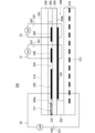
- FIG. 1 is a diagram illustrating an example of a configuration of a gas sensor 100.
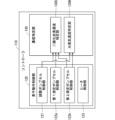
- FIG. FIG. 1 is a block diagram showing functional components implemented in a controller 110.
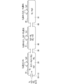
- 2 is a schematic diagram showing how gas flows in and out of three chambers in a sensor element 101 of a gas sensor 100.
- FIG. FIG. 10 is a diagram illustrating the dependence of the oxygen pump current Ip0 on the concentration of the H/C component when the measurement gas contains the H/C component.
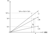
- FIG. 13 is a diagram showing the dependence of the oxygen pump current Ip1 on the concentration of the target gas component.
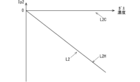
- FIG. 13 is a diagram showing the dependence of the oxygen pump current Ip2 on the concentration of the target gas component.
- FIG. 10 is a diagram illustrating an example of the configuration of a gas sensor 200 according to a modified example.
- FIG. 1 is a diagram showing an example of the configuration of a gas sensor 100 according to the present embodiment.
- the gas sensor 100 is a multi-gas sensor that detects a plurality of types of gas components using a sensor element 101 and measures their concentrations. In the present embodiment, it is assumed that at least water vapor (H 2 O) and carbon dioxide (CO 2 ) are the main gas components to be detected by the gas sensor 100.
- the gas sensor 100 is attached to an exhaust path of an internal combustion engine such as an automobile engine, and is used in a mode in which the exhaust gas flowing through the exhaust path is the measured gas.
- FIG. 1 includes a vertical cross-sectional view along the longitudinal direction of the sensor element 101.
- the sensor element 101 has a long plate-shaped structure (base portion) 14 made of an oxygen ion conductive solid electrolyte, a first diffusion rate-controlling portion 11 formed at one end (left end in the drawing) of the structure 14 and also serving as a gas inlet 10 through which the gas to be measured is introduced, and a buffer space 12, a first chamber 20, a second chamber 40, and a third chamber 61 formed within the structure 14 and sequentially communicating with the gas inlet 10 (first diffusion rate-controlling portion 11).
- the buffer space 12 communicates with the gas inlet 10 (first diffusion rate-controlling portion 11).
- the first chamber 20 communicates with the buffer space 12 via the second diffusion rate-controlling portion 13.
- the second chamber 40 communicates with the first chamber 20 via the third diffusion rate-controlling portion 30.
- the third chamber 61 communicates with the second chamber 40 via the fourth diffusion rate-controlling portion 60.
- the structure 14 is formed by stacking multiple layers of substrates made of, for example, ceramics. Specifically, the structure 14 has a configuration in which six layers, including a first substrate 1, a second substrate 2, a third substrate 3, a first solid electrolyte layer 4, a spacer layer 5, and a second solid electrolyte layer 6, are stacked in this order from the bottom up. Each layer is formed of an oxygen ion conductive solid electrolyte such as zirconia (ZrO 2 ).
- ZrO 2 zirconia
- the first diffusion rate-controlling section 11, which also serves as the gas inlet 10, the buffer space 12, the second diffusion rate-controlling section 13, the first chamber 20, the third diffusion rate-controlling section 30, the second chamber 40, the fourth diffusion rate-controlling section 60, and the third chamber 61 are formed in this order on one end side of the structure 14 between the lower surface 6b of the second solid electrolyte layer 6 and the upper surface 4a of the first solid electrolyte layer 4.
- the portion from the gas inlet 10 to the third chamber 61 is also referred to as the gas flow section.
- the buffer space 12, the first chamber 20, the second chamber 40, and the third chamber 61 are formed so as to penetrate the spacer layer 5 in the thickness direction. At the top of these chambers, the lower surface 6b of the second solid electrolyte layer 6 is exposed, and at the bottom of the drawing, the upper surface 4a of the first solid electrolyte layer 4 is exposed.
- the sides of these chambers are partitioned by the spacer layer 5 or any of the diffusion rate-controlling parts.
- the length (size in the longitudinal direction of the element) of the first chamber 20, the second chamber 40, and the third chamber 61 is, for example, 0.3 mm to 1.0 mm
- the width (size in the lateral direction of the element) is, for example, 0.5 mm to 30 mm
- the height (size in the thickness direction of the element) is, for example, 50 ⁇ m to 200 ⁇ m.
- the sizes of the chambers do not need to be the same and may be different.
- the gas inlet 10 may be formed separately from the first diffusion rate-controlling section 11 so as to penetrate the spacer layer 5 in the thickness direction.
- the first diffusion rate-controlling section 11 is formed adjacent to and inside the gas inlet 10.
- the first diffusion rate-controlling section 11, the second diffusion rate-controlling section 13, the third diffusion rate-controlling section 30, and the fourth diffusion rate-controlling section 60 each have two horizontally long slits. That is, they have openings at the top and bottom as viewed in the drawing that extend long in a direction perpendicular to the drawing.
- the length of the slits (size in the longitudinal direction of the element) is, for example, 0.2 mm to 1.0 mm
- the width of the opening (size in the transverse direction of the element) is, for example, 0.5 mm to 30 mm
- the height of the opening (size in the thickness direction of the element) is, for example, 5 ⁇ m to 30 ⁇ m.
- a reference gas introduction space 43 is provided at the other end (the right end as viewed in the drawing) of the sensor element 101 opposite to the end where the gas introduction port 10 is provided.
- the reference gas introduction space 43 is formed between the upper surface 3a of the third substrate 3 and the lower surface 5b of the spacer layer 5.
- the side of the reference gas introduction space 43 is partitioned by the side surface of the first solid electrolyte layer 4.
- oxygen ( O2 ) or air is introduced as a reference gas.
- the gas inlet 10 (first diffusion rate limiting section 11) is a section that opens to the external space, and the gas to be measured is taken into the sensor element 101 from the external space through the gas inlet 10.
- the first diffusion rate-controlling section 11 is a section that provides a predetermined diffusion resistance to the taken-in measurement gas.
- the buffer space 12 is provided to counteract the concentration fluctuations of the measured gas caused by pressure fluctuations of the measured gas in the external space.
- An example of such pressure fluctuations of the measured gas is the pulsation of the exhaust pressure of automobile exhaust gas.
- the second diffusion rate-controlling section 13 is a section that imparts a predetermined diffusion resistance to the measurement gas that is introduced from the buffer space 12 into the first chamber 20.
- the first chamber 20 is provided as a space for oxidizing the hydrocarbon gas components (H/C components) with oxygen pumped in from the external space when the measured gas introduced through the second diffusion rate-controlling section 13 contains such H/C components.
- the pumping in of such oxygen is achieved by the operation of the adjustment pump cell 21.
- oxygen may be pumped out of the first chamber 20 by the adjustment pump cell 21.
- the adjustment pump cell 21 is an electrochemical pump cell composed of an inner pump electrode (adjustment electrode) 22, an outer pump electrode (outside the cavity pump electrode) 23, and a solid electrolyte present in the portion of the structure 14 sandwiched between the two electrodes.
- a voltage Vp0 is applied between the inner pump electrode 22 and the outer pump electrode 23 by a variable power supply 24 provided outside the sensor element 101, generating an oxygen pump current (oxygen ion current) Ip0.
- This makes it possible to pump oxygen into the first chamber 20 from the external space, or pump oxygen out of the first chamber 20 to the external space.
- the direction of the oxygen pump current Ip0 when oxygen is pumped out of the first chamber 20 is set to the positive direction of the oxygen pump current Ip0.
- the inner pump electrode 22 is provided as a ceiling electrode portion 22a and a bottom electrode portion 22b on substantially the entire surface of the lower surface 6b of the second solid electrolyte layer 6 that defines the first chamber 20 and substantially the entire surface of the upper surface 4a of the first solid electrolyte layer 4, respectively.
- the ceiling electrode portion 22a and the bottom electrode portion 22b are connected by a conductive portion (not shown).
- the inner pump electrode 22 is provided as a porous cermet electrode that is rectangular in plan view and contains at least one of platinum and rhodium (Rh) as a metal component.
- the outer pump electrode 23 is provided as a porous cermet electrode having a rectangular shape in plan view, containing platinum or an alloy of platinum and gold (Pt-Au alloy) as the metal component, for example, platinum or a Pt-Au alloy and zirconia.
- the first vacant chamber sensor cell 80 is composed of the inner pump electrode 22, the reference electrode 42, and a solid electrolyte present in the portion of the structure 14 sandwiched between the two electrodes.
- the first vacant chamber sensor cell 80 is an electrochemical sensor cell for determining the oxygen partial pressure in the atmosphere in the first vacant chamber 20.
- the reference electrode 42 is an electrode formed between the first solid electrolyte layer 4 and the third substrate 3, and is provided, for example, as a porous cermet electrode that contains platinum and zirconia and has a rectangular shape in a plan view.
- a reference gas introduction layer 48 made of porous alumina and connected to the reference gas introduction space 43 is provided around the reference electrode 42.
- the reference gas in the reference gas introduction space 43 is introduced to the surface of the reference electrode 42 through the reference gas introduction layer 48. In other words, the reference electrode 42 is always in contact with the reference gas.
- an electromotive force (Nernst electromotive force) V0 is generated between the inner pump electrode 22 and the reference electrode 42.
- the electromotive force V0 has a value that corresponds to the difference between the oxygen concentration (oxygen partial pressure) in the first chamber 20 and the oxygen concentration (oxygen partial pressure) of the reference gas.
- the electromotive force V0 has a value that corresponds to the oxygen concentration (oxygen partial pressure) in the first chamber 20.
- the third diffusion control section 30 is a section that provides a predetermined diffusion resistance to the measurement gas that is introduced from the first chamber 20 to the second chamber 40 and that does not substantially contain H/C components.
- the second chamber 40 is provided as a space for pumping out oxygen from the measurement gas introduced through the third diffusion rate-controlling part 30, and further for reducing (decomposing) H 2 O and CO 2 contained in the measurement gas as detection target gas components to generate hydrogen (H 2 ) and carbon monoxide (CO), so that the measurement gas does not substantially contain oxygen, H 2 O, and CO 2.
- the pumping out of oxygen and the reduction (decomposition) of H 2 O and CO 2 are realized by the operation of the first measurement pump cell 50.
- the first measurement pump cell 50 is an electrochemical pump cell composed of a first measurement electrode 51, an outer pump electrode 23, and a solid electrolyte present in the portion of the structure 14 sandwiched between the two electrodes.
- a voltage Vp1 is applied between the first measurement electrode 51 and the outer pump electrode 23 by a variable power supply 52 provided outside the sensor element 101, generating an oxygen pump current (oxygen ion current) Ip1.
- oxygen pump current oxygen ion current
- the direction of the oxygen pump current Ip1 when oxygen is pumped out of the second chamber 40 is set to the positive direction of the oxygen pump current Ip1.
- the first measurement electrode 51 is provided as a ceiling electrode portion 51a and a bottom electrode portion 51b on substantially the entire surface of the lower surface 6b of the second solid electrolyte layer 6 that defines the second chamber 40 and substantially the entire surface of the upper surface 4a of the first solid electrolyte layer 4.
- the ceiling electrode portion 51a and the bottom electrode portion 51b are connected by a conductive portion (not shown).
- the first measurement electrode 51 is provided as a porous cermet electrode having a rectangular shape in a plan view and containing Pt as a metal component.
- the second vacant chamber sensor cell 81 is composed of the first measurement electrode 51, the reference electrode 42, and a solid electrolyte present in the portion of the structure 14 sandwiched between the two electrodes.
- the second vacant chamber sensor cell 81 is an electrochemical sensor cell for determining the oxygen partial pressure in the atmosphere in the second vacant chamber 40.
- an electromotive force (Nernst electromotive force) V1 is generated between the first measurement electrode 51 and the reference electrode 42.
- the electromotive force V1 has a value that corresponds to the difference between the oxygen concentration (oxygen partial pressure) in the second chamber 40 and the oxygen concentration (oxygen partial pressure) of the reference gas.
- the electromotive force V1 has a value that corresponds to the oxygen concentration (oxygen partial pressure) in the second chamber 40.
- the fourth diffusion rate-controlling portion 60 is a portion that provides a predetermined diffusion resistance to the measurement gas that is introduced from the second chamber 40 to the third chamber 61 and contains H2 and CO but substantially no H2O , CO2 , or oxygen.
- the third chamber 61 is provided as a space for selectively oxidizing all of H2 out of H2 and CO contained in the measurement gas introduced through the fourth diffusion-controlling part 60 to generate H2O again.
- the generation of H2O by the oxidation of H2 is realized by the operation of the second measurement pump cell 41.
- the second measurement pump cell 41 is an electrochemical pump cell composed of a second measurement electrode 44, an outer pump electrode 23, and a solid electrolyte present in the portion of the structure 14 sandwiched between the two electrodes.
- a voltage Vp2 is applied between the second measurement electrode 44 and the outer pump electrode 23 by a variable power supply 46 provided outside the sensor element 101, generating an oxygen pump current (oxygen ion current) Ip2.
- oxygen pump current oxygen ion current
- the direction of the oxygen pump current Ip2 when oxygen is pumped out of the third chamber 61 is set to the positive direction of the oxygen pump current Ip2.
- the second measurement electrode 44 is provided on substantially the entire upper surface 4a of the first solid electrolyte layer 4 that defines the third chamber 61.
- the second measurement electrode 44 is provided as a porous cermet electrode having a rectangular shape in plan view, which contains a Pt-Au alloy as a metal component, for example, the Pt-Au alloy and zirconia.
- the Au concentration in the Pt-Au alloy is preferably 1 wt% or more and 50 wt% or less, and more preferably 10 wt% or more and 30 wt% or less.
- the selective oxidation of H 2 at the second measurement electrode 44 that is, the property that when H 2 and CO coexist in the third chamber 61, only H 2 is selectively oxidized by oxygen pumped in by the second measurement pump cell 41, and CO is not oxidized, is more suitably expressed.
- the third vacant chamber sensor cell 82 is composed of the second measurement electrode 44, the reference electrode 42, and a solid electrolyte present in the portion of the structure 14 sandwiched between the two electrodes.
- the third vacant chamber sensor cell 82 is an electrochemical sensor cell for determining the oxygen partial pressure in the atmosphere in the third vacant chamber 61.
- an electromotive force (Nernst electromotive force) V2 is generated between the second measurement electrode 44 and the reference electrode 42.
- the electromotive force V2 has a value that corresponds to the difference between the oxygen concentration (oxygen partial pressure) in the third chamber 61 and the oxygen concentration (oxygen partial pressure) of the reference gas.
- the electromotive force V2 has a value that corresponds to the oxygen concentration (oxygen partial pressure) in the third chamber 61.
- the sensor element 101 further includes an electrochemical sensor cell 83 that is composed of an outer pump electrode 23, a reference electrode 42, and a solid electrolyte that is present in the portion of the structure 14 that is sandwiched between the two electrodes.
- the electromotive force Vref that is generated between the outer pump electrode 23 and the reference electrode 42 in the sensor cell 83 has a value that corresponds to the oxygen partial pressure of the measured gas that is present outside the sensor element 101.
- the sensor element 101 is equipped with a heater section 70 that serves to adjust the temperature by heating and keeping the sensor element 101 warm in order to increase the oxygen ion conductivity of the solid electrolyte that constitutes the structure 14.
- the heater section 70 mainly comprises a heater electrode 71, a heater element 72, a heater lead 72a, a through hole 73, a heater insulating layer 74, and a heater resistance detection lead (not shown in FIG. 1).
- the heater element 72 will also be referred to simply as the heater 72.
- the heater 72 is sandwiched between the second substrate 2 and the third substrate 3 from above and below, and generates heat when power is supplied from the outside through the heater electrode 71, through hole 73, and heater lead 72a provided on the underside 1b of the first substrate 1.
- the heater 72 is embedded throughout the entire range from the buffer space 12 to the third chamber 61, and is capable of heating the sensor element 101 to a predetermined temperature and keeping it warm.
- the heater 72 is arranged so that when heated, the temperature is highest near the first chamber 20 (near the adjustment electrode 22) and decreases the further away from the first chamber 20 in the element longitudinal direction.
- the temperature in the range from one end of the sensor element 101 equipped with the gas inlet 10 to the third chamber 61 when the gas sensor 100 is used (when the sensor element 101 is driven) is referred to as the element drive temperature.
- the heater 72 heats so that the element drive temperature is within the range of 750°C to 950°C.
- Heater insulating layers 74 made of alumina or the like are formed above and below the heater 72 in order to provide electrical insulation between the second substrate 2 and the third substrate 3.
- the heater section 70 also has a pressure release hole 75.
- the pressure release hole 75 is a portion that penetrates the third substrate 3 and is provided so as to communicate with the reference gas introduction space 43, and is provided for the purpose of mitigating the increase in internal pressure that accompanies a rise in temperature within the heater insulating layer 74.
- the gas sensor 100 also includes a controller 110 that controls the operation of the sensor element 101 and is responsible for determining the concentration of the gas component to be detected based on the current flowing through the sensor element 101.
- FIG. 2 is a block diagram showing the functional components realized in the controller 110.
- the controller 110 is composed of one or more electronic circuits having, for example, one or more CPUs (Central Processing Units) and a memory device.
- the electronic circuit is also a software function unit in which specific functional components are realized by, for example, the CPU executing a specific program stored in the memory device.
- it may also be composed of an integrated circuit such as an FPGA (Field-Programmable Gate Array) in which multiple electronic circuits are connected according to their functions.
- FPGA Field-Programmable Gate Array
- the gas sensor 100 When the gas sensor 100 is attached to the exhaust path of an automobile engine and the exhaust gas flowing through the exhaust path is used as the gas to be measured, some or all of the functions of the controller 110 may be realized by the automobile's ECU (electronic control unit).
- ECU electronic control unit
- the controller 110 includes, as functional components realized by the execution of a specific program in the CPU, an element operation control unit 120 that controls the operation of each part of the sensor element 101 described above, and a concentration determination unit 130 that is responsible for the process of determining the concentration of the target gas component contained in the measured gas.
- the element operation control unit 120 mainly comprises an adjustment pump cell control unit 121 that controls the operation of the adjustment pump cell 21, a first measurement pump cell control unit 122a that controls the operation of the first measurement pump cell 50, a second measurement pump cell control unit 122b that controls the operation of the second measurement pump cell 41, and a heater control unit 123 that controls the heating operation by the heater 72.
- the concentration specifying unit 130 mainly includes a water vapor concentration specifying unit 130H and a carbon dioxide concentration specifying unit 130C that respectively specify the concentrations of H 2 O and CO 2 , which are the main detection target gas components in the gas sensor 100 .
- the water vapor concentration determination unit 130H determines the concentration of H2O contained in the measured gas based on the value of the oxygen pump current Ip0 flowing through the adjustment pump cell 21 acquired by the adjustment pump cell control unit 121 and the value of the oxygen pump current Ip2 flowing through the second measurement pump cell 41 acquired by the second measurement pump cell control unit 122b.
- the carbon dioxide concentration determination unit 130C determines the concentration of CO2 contained in the measured gas based on the concentration of H2O determined in the water vapor concentration determination unit 130H (the value of the oxygen pump current Ip2 that is the basis for the determination), the value of the oxygen pump current Ip0 flowing through the adjustment pump cell 21 acquired by the adjustment pump cell control unit 121, and the value of the oxygen pump current Ip1 flowing through the first measurement pump cell 50 acquired by the first measurement pump cell control unit 122a.
- Multi-gas detection and concentration identification> a method of detecting a plurality of gas species (multi-gas detection) and identifying the concentration of the detected gases, which are realized by the gas sensor 100 having the above-mentioned configuration, will be described.
- the measurement gas is an exhaust gas that essentially contains oxygen, H2O , and CO2 and may contain H/C components.
- Figure 3 is a schematic diagram showing how gas flows in and out of three chambers (internal spaces) in the sensor element 101 of the gas sensor 100.
- the measurement gas is introduced into the first chamber 20 through the gas inlet 10 (first diffusion rate-controlling section 11), the buffer space 12, and the second diffusion rate-controlling section 13.
- the adjustment pump cell 21 is operated to pump oxygen in from the external space or pump oxygen out to the external space to keep the oxygen concentration (or oxygen partial pressure) constant.
- FIG. 3 only shows the case where oxygen is pumped in.
- the pumping in or pumping out of oxygen is performed by the adjustment pump cell control unit 121 of the controller 110 setting the target value (control voltage) of the electromotive force V0 in the first chamber sensor cell 80 to a value within the range of 400 mV to 700 mV (preferably 400 mV), and feedback-controlling the voltage Vp0 applied by the variable power supply 24 to the adjustment pump cell 21 in accordance with the difference between the actual value of the electromotive force V0 and the target value so that the electromotive force V0 is maintained at the target value.
- the adjustment pump cell control unit 121 controls the pump voltage Vp0 applied by the variable power supply 24 to the adjustment pump cell 21 so as to reduce the displacement, thereby pumping oxygen into the first chamber 20.
- the measurement gas contains H/C components
- oxygen is pumped into the first chamber 20 by the adjustment pump cell 21, and a reaction occurs in which the H/C components are oxidized to H 2 O and CO 2 .
- the target value of the electromotive force V0 may be set so that oxygen is pumped in to the extent that the H/C components are substantially all oxidized.
- the extent to which the H/C components are substantially all oxidized means that the H / C components are allowed to remain to the extent that they do not affect the measurement accuracy of the concentrations of H 2 O and CO 2. In this case, the pumping in of oxygen in a situation where the measured gas does not contain H/C components is suppressed.
- oxygen may be pumped out depending on the target value of the electromotive force V0 that is set (depending on the target value of the oxygen concentration or oxygen partial pressure in the first chamber 20).
- the oxygen partial pressure in the first chamber 20 is maintained at a value according to the target value of the electromotive force V0.
- V0 400 mV
- the oxygen partial pressure is about 10 ⁇ 8 atm.
- the measurement gas that does not substantially contain H/C components is introduced into the second chamber 40.
- oxygen contained in the measurement gas is pumped out and H 2 O and CO 2 are reduced. That is, the first measurement pump cell 50 is operated, oxygen is pumped out from the measurement gas introduced into the second chamber 40, and the reduction (decomposition) reaction (2H 2 O ⁇ 2H 2 +O 2 , 2CO 2 ⁇ 2CO+O 2 ) of H 2 O and CO 2 contained in the measurement gas proceeds, and substantially all of H 2 O and CO 2 are decomposed into hydrogen (H 2 ), carbon monoxide (CO), and oxygen.
- the H 2 O contained in the measurement gas includes both H 2 O already contained in the measurement gas when it is introduced from the outside and H 2 O generated by oxidation of the H/C components.
- the pumping of oxygen and the reduction (decomposition) of H2O and CO2 are carried out by the first measurement pump cell control section 122a of the controller 110 setting the target value (control voltage) of the electromotive force V1 in the second vacant room sensor cell 81 to a value within the range of 1000 mV to 1500 mV (preferably 1000 mV), and feedback-controlling the voltage Vp1 applied by the variable power supply 52 to the first measurement pump cell 50 in accordance with the difference between the actual value of the electromotive force V1 and the target value so that the electromotive force V1 is maintained at the target value.
- the oxygen partial pressure in the second chamber 40 is maintained at a value lower than the oxygen partial pressure in the first chamber 20.
- the oxygen partial pressure is about 10 ⁇ 20 atm.
- the measurement gas contains substantially no H 2 O, CO 2 , or oxygen.
- a measurement gas containing H 2 and CO but substantially free of H 2 O, CO 2 and oxygen is introduced into the third chamber 61 .
- oxygen is pumped in by the operation of the second measuring pump cell 41, and only H2 contained in the introduced measurement gas is selectively oxidized.
- the pumping of oxygen is performed by the second measurement pump cell control section 122b of the controller 110 setting the target value (control voltage) of the electromotive force V2 in the third vacant chamber sensor cell 82 to a value within the range of 250 mV to 450 mV (preferably 350 mV), and feedback-controlling the voltage Vp2 applied by the variable power supply 46 to the second measurement pump cell 41 in accordance with the difference between the actual value of the electromotive force V2 and the target value so that the electromotive force V2 is maintained at the target value.
- the oxidation (combustion) reaction of 2H 2 +O 2 ⁇ 2H 2 O is promoted in the third chamber 61, and an amount of H 2 O that is correlated with the total amount of H 2 O introduced from the gas inlet 10 and H 2 O generated by oxidation of the H/C components in the first chamber 20 is generated again.
- the amount of H 2 O that is correlated means that the total amount of H 2 O introduced from the gas inlet 10 and H 2 O generated by oxidation of the H/C components in the first chamber 20 and the amount of H 2 O generated again by oxidation of the H 2 generated by their decomposition are the same or within a certain error range that is allowable from the viewpoint of measurement accuracy.
- the oxygen partial pressure in the third chamber 61 is maintained within a range in which H2 is almost entirely oxidized but CO is not oxidized.
- providing the second measurement electrode 44 as a cermet electrode containing a Pt-Au alloy having an Au concentration of 1 wt % or more and 50 wt % or less as a metal component also contributes to improving the selective oxidation of H 2 .
- a cermet electrode containing a Pt-Au alloy is provided in the second chamber 40, and oxygen for the selective oxidation of H2 is pumped in by a pump cell including such an electrode, whereas in the present application, a first measurement electrode 51 not including Au as a metal component is provided in the second chamber 40, and a second measurement electrode 44 having a Pt-Au alloy as a metal component and responsible for the selective oxidation of H2 is provided facing a third chamber 61 whose temperature during operation of the gas sensor 100 is lower than that of the second chamber 40.
- the shape (width, thickness) and arrangement (denseness) of the heater 72 may be modified to further suppress the temperature rise of the second measurement electrode 44.
- the concentrations of H2O and CO2 in the measured gas are determined based on the oxygen pump current Ip0 that flows through the adjustment pump cell 21 when oxygen is pumped in to oxidize the H / C components, the oxygen pump current Ip1 that flows through the first measurement pump cell 50 when oxygen is pumped out including the reduction of H2O and CO2 , and the oxygen pump current Ip2 that flows through the second measurement pump cell 41 when oxygen is pumped in for the oxidation of H2 .
- Figure 4 is a diagram that shows the dependence of the oxygen pump current Ip0 on the concentration of H/C components when the measured gas contains H/C components.
- the value of the oxygen pump current Ip0 can be considered to change according to the concentration of the H/C components, which changes from moment to moment.
- the graph L0 passes through the origin, but more specifically, the intersection point of the graph L0 with the vertical axis changes depending on the target value of the electromotive force V0 in the first vacant room sensor cell 80.
- Fig. 5 is a diagram illustrating the gas concentration dependency of the oxygen pump current Ip1 in a measurement gas that does not contain H/C components. Specifically, Fig. 5 shows a schematic diagram of the dependency of the oxygen pump current Ip1 on the concentration of the target gas component when only one of H2O and CO2 is contained alone as the main target gas component, and when H2O and CO2 are contained in equal concentrations.
- FIG 5 shows a graph L1H in the case where H 2 O is contained solely as the target gas component, a graph L1C in the case where CO 2 is contained solely as the target gas component, and a graph L1 in the case where equal concentrations of H 2 O and CO 2 are contained as the target gas components. Note that these graphs can actually be obtained by operating the gas sensor 100 in an atmosphere of a model gas in which the concentrations of the target gas components are known and the remainder is oxygen and nitrogen.
- the graphs L1H, L1C, and L1 are all monotonically increasing straight lines. Moreover, the value Ip1h +c of the oxygen pump current Ip1 when the measurement gas contains H2O and CO2 equally as detection target gas components at a certain gas concentration a is the sum of the oxygen pump current values Ip1h and Ip1c when the measurement gas contains H2O and CO2 alone at the gas concentration a.
- the value of the oxygen pump current Ip1 when the ratio of H2O to CO2 is changed is the sum of the oxygen pump current Ip1 when H2O or CO2 is contained alone at a concentration according to each ratio.
- the oxygen that is pumped out of the second chamber 40 by the first measuring pump cell 50 to generate the oxygen pump current Ip1 can be of four types: (a) oxygen originally contained in the measured gas, (b) oxygen produced by reduction of H2O and CO2 originally contained in the measured gas, (c) oxygen pumped into the first chamber 20 by the adjustment pump cell 21, and (d) oxygen produced when the H2O and CO2 produced by the oxidation of the H/C components contained in the measured gas due to such pumping are reduced.
- the oxygen pump current Ip1 corresponds to the amounts of these oxygens (a) to (d).
- the oxygens (c) and (d) are oxygen that have been pumped into the first chamber 20 by the adjustment pump cell 21 in the first place.
- the sum of the contributions of the oxygens (c) and (d) to the oxygen pump current Ip1 can be considered to be equal to the absolute value
- (a) and (b) correspond to Ip1r in equation (1).
- Ip1r Ip1t -
- the oxygen pump current Ip1 when the measured gas contains H/C components can be treated in the same way as the measured gas containing only oxygen (a) and ( b ) that is related by equation (1) and does not contain H/C components, with respect to the actual reduction current value Ip1r obtained by subtracting the absolute value
- the actual reduction current value Ip1r obtained by subtracting the absolute value of the oxygen pump current Ip0 flowing through the adjustment pump cell 21 from the value of the oxygen pump current Ip1 flowing through the first measurement pump cell 50, which is obtained from equation (2), can be applied to equation (1) in the same way as in the case of a measurement gas that does not contain H/C.
- Ip1r Ip1t (3) That is, when oxygen is being pumped out of the first chamber 20, the actual reduction current value Ip1r is nothing but the value of the oxygen pump current Ip1 itself. Even in this case, formula (1) and the above-mentioned linear relationship can be applied.
- Fig. 6 is a diagram illustrating the gas concentration dependency of the oxygen pump current Ip2 in a measurement gas that does not contain H / C components. Specifically, Fig. 6 shows a schematic diagram of the dependency of the oxygen pump current Ip2 on the concentration of the target gas component when only one of H2O and CO2 is contained alone as the main target gas component, and when H2O and CO2 are contained in equal concentrations.
- FIG. 6 shows a graph L2H in the case where H 2 O is contained solely as the target gas component, a graph L2C in the case where CO 2 is contained solely as the target gas component, and a graph L2 in the case where equal concentrations of H 2 O and CO 2 are contained as the target gas components. Note that these graphs can actually be obtained by operating the gas sensor 100 in an atmosphere of a model gas in which the concentrations of the target gas components are known and the remainder is oxygen and nitrogen.
- the graph L2H of the oxygen pump current Ip2 monotonically decreases (the absolute value monotonically increases). Note that the oxygen pump current Ip2 has a negative value because, while the direction of pumping oxygen in the second measurement pump cell 41 is the positive direction of the oxygen pump current as described above, the oxygen pump current Ip2 flows in a direction of pumping oxygen in order to reoxidize the H2 generated by reduction in the second chamber 40.
- the graph L2C of the oxygen pump current Ip2 is constant at 0 regardless of the gas concentration. This corresponds to the fact that the CO generated by reduction in the second chamber 40 is not reoxidized by the operation of the second measurement pump cell 41.
- the graph L2 of the oxygen pump current Ip2 when equal concentrations of H 2 O and CO 2 are contained as detection target gas components coincides with the graph L2H of the oxygen pump current Ip2 when only H 2 O is contained.
- the value of the oxygen pump current Ip2 when the ratio of H2O to CO2 is changed is approximately the same as graph L2 of the oxygen pump current Ip2 when the mixture contains only H2O or CO2 at a concentration according to the respective ratio.
- the H2 and CO flowing into the third chamber 61 also contain H2 and CO produced by the reduction in the second chamber 40 of H2O and CO2 produced by the oxidation of the H/C components in the first chamber 20. Therefore, oxygen for oxidizing H2 derived from the H/C components also contributes to the oxygen pump current Ip2 in this case.
- the value Ip2t of the actual pump current Ip2 is a value obtained by superposing the values Ip2r and Ip2HC . Note that, since the oxygen pump current Ip2 has a positive direction in which oxygen is pumped out, the values Ip2t , Ip2r , and Ip2HC are all negative.
- the value Ip2HC derived from the H/C component is the value Ip0 of the oxygen pump current Ip0 multiplied by a predetermined coefficient ⁇ (0 ⁇ 1) indicating the ratio of hydrogen present in the H/C component. This is because, while H2O and CO2 produced by the oxidation of the H/C component are both reduced in the second chamber 40, only H2 is reoxidized in the third chamber 61 out of the H2 and CO produced by the reduction.
- the coefficient ⁇ is a value according to the type of hydrocarbons that make up the H/C components contained in the measured gas (more specifically, the atomic ratio of H atoms to C atoms that make up the hydrocarbons), and can be experimentally determined in advance by mass spectrometry or the like. Multiple coefficients ⁇ that correspond to the type and composition of the H/C components may be specified and used selectively.
- Equation (5) consists only of the actual measured value of the pump current and the known coefficient ⁇ , if a linear relationship between the oxygen pump current Ip2 and the gas concentration, such as that shown in graph L2H, is specified in advance using a model gas, then when specifying the concentrations of H2O and CO2 in a measurement gas containing H/ C components, this linear relationship can be applied to the value Ip2r obtained by substituting the pump current value obtained by measurement using gas sensor 100 into the right side of equation (5).
- the above-described properties of the oxygen pump current Ip0, the oxygen pump current Ip1, and the oxygen pump current Ip2 are utilized to measure the concentrations of H2O and CO2 in the measurement gas.
- the oxygen pump current Ip0, the oxygen pump current Ip1, and the oxygen pump current Ip2 during actual measurement by the gas sensor 100 are also referred to as the H/C oxidation current Ip0, the total reduction current Ip1, and the water vapor equivalent current Ip2, respectively.
- characteristic data showing the relationship between the oxygen pump current Ip1 and the concentration of each gas when the measurement gas contains only H2O and CO2 but not the other and does not contain H/C components, as in graphs L1H and L1C shown in Fig. 5
- characteristic data hereinafter referred to as Ip2- H2O data
- Ip1- H2O data and Ip1- CO2 data are values indicating the contribution of H2O and the contribution of CO2 to the total reduction current Ip1, respectively.
- the oxygen pump current Ip1 is a value corresponding to the diffusion resistance given to the measurement gas from the gas inlet 10 of the sensor element 101 to the second chamber 40
- the oxygen pump current Ip2 is a value corresponding to the diffusion resistance given to the measurement gas from the gas inlet 10 of the sensor element 101 to the third chamber 61. Therefore, strictly speaking, the Ip1-H 2 O data, the Ip1-CO 2 data, and the Ip2-H 2 O data are different for each individual sensor element 101 constituting each gas sensor 100. Therefore, it is preferable that these characteristic data are specified for each gas sensor 100. However, for gas sensors 100 manufactured under the same conditions and in the same lot, if it is confirmed that the error is within the allowable range, the characteristic data obtained for a certain gas sensor 100 may be applied to other gas sensors 100 in the same lot.
- the gas to be measured is introduced into the sensor element 101, which has been heated to the element driving temperature, and the adjustment pump cell 21, the first measurement pump cell 50, and the second measurement pump cell 41 operate in the manner described above.
- the water vapor concentration specifying unit 130H obtains the H/C oxidation current Ip0 from the adjustment pump cell control unit 121, and obtains the water vapor equivalent current Ip2 from the second measurement pump cell control unit 122b.
- the water vapor concentration specifying unit 130H calculates the value Ip2r based on formula (5) when the H/C oxidation current Ip0 is negative, and based on formula (6) when the H/C oxidation current Ip0 is positive.
- the water vapor concentration specifying unit 130H determines the H 2 O concentration corresponding to the obtained value based on the Ip2-H 2 O data.
- the carbon dioxide concentration determination unit 130C subsequently obtains the H/C oxidation current Ip0 from the adjustment pump cell control unit 121 and obtains the value Ip1t of the total reduction current Ip1 from the first measurement pump cell control unit 122a. If the H/C oxidation current Ip0 is negative, the unit 130C calculates the actual reduction current value Ip1r, which is the pump current value obtained by excluding the contribution of the H/C component from the total reduction current Ip1, based on equation (2) if the H/C oxidation current Ip0 is negative, and based on equation (3) if the H/C oxidation current Ip0 is positive.
- the contribution of H2O at the concentration specified by the water vapor concentration specifying unit 130H out of the calculated actual reduction current value Ip1r is specified, i.e., the current value Ip1h due to the reduction of H2O originally contained in the measured gas out of the total reduction current Ip1 is specified.
- the obtained value is subtracted from the actual reduction current value Ip1r to specify the CO2 contribution Ip1c in the total reduction current Ip1.
- the CO2 concentration corresponding to the CO2 contribution Ip1c is specified.
- the H 2 O concentration and the CO 2 concentration in the measurement gas are measured in the manner described above.
- the concentrations of H2O and CO2 can be measured while eliminating the influence of the H/C components.
- the voltage applied to the adjustment pump cell which pumps oxygen in and out between the first chamber and the outside is kept low compared to the gas sensors of the prior art which pump oxygen out from the first chamber, so that the occurrence of cracks and blackening in the sensor element is suitably suppressed.
- the only electrode in the chamber that uses a Pt-Au alloy as the metal component is the second measurement electrode provided in the third chamber.
- No electrodes using a Pt-Au alloy are provided in the first and second chambers, which are hotter than the third chamber, so evaporation of Au from the electrodes is suppressed compared to conventional technology.
- this embodiment realizes a multi-gas sensor with better long-term reliability than conventional sensors.
- the sensor element 101 is provided with a gas flow section including a first chamber 20, a second chamber 40, and a third chamber 61 that communicate with each other through a diffusion rate limiting section.
- the measurement gas is sequentially introduced into each chamber under a predetermined diffusion resistance.
- oxygen is pumped in or out by the adjustment pump cell 21, and if the measurement gas contains H/C components, the H/C components are oxidized by the pumped-in oxygen.
- oxygen is pumped out by the first measuring pump cell 50, thereby reducing H 2 O and CO 2.
- the H 2 produced by the reduction of H 2 O is selectively oxidized by the second measuring pump cell 41.
- the concentrations of H 2 O and CO 2 in the measurement gas are measured based on the magnitude of the current flowing through each pump cell.
- Such a measurement mode in the gas sensor 100 is realized by the first diffusion rate-controlling part 11 and the second diffusion rate-controlling part 13 suppressing the inflow of the measurement gas from the outside of the element into the first chamber 20, the third diffusion rate-controlling part 30 suppressing the inflow of the measurement gas containing remaining oxygen from the first chamber 20 to the second chamber 40, and the fourth diffusion rate-controlling part 60 suppressing the inflow of the measurement gas containing remaining H 2 O and CO 2 from the second chamber 40 to the third chamber 61.
- the measurement gas reaching the inner pump electrode 22 of the adjustment pump cell 21, the first measurement electrode 51 of the first measurement pump cell 50, and the second measurement electrode 44 of the second measurement pump cell 41 is appropriately controlled by the respective diffusion rate-controlling parts, and gases not targeted by the operation of the respective pump cells are prevented from reaching the respective electrodes, thereby enabling the gas sensor 100 to detect multiple gases.
- Fig. 7 is a diagram showing an example of the configuration of a gas sensor 200 according to a modified example based on the above points.
- the gas sensor 200 is a multi-gas sensor that detects a plurality of types of gas components using a sensor element 201 and measures their concentrations.
- the gas sensor 200 is controlled by a controller 110 to perform multi-gas detection with at least water vapor ( H2O ) and carbon dioxide ( CO2 ) as the main gas components to be detected, as described below.
- Fig. 7 includes a vertical cross-sectional view along the longitudinal direction of the sensor element 201.
- the sensor element 201 is a long plate-shaped structure in which a sensor section 214 and a heater section 270 are stacked.
- the sensor section 214 is constructed by stacking multiple substrate layers made of ceramics. Specifically, the sensor section 214 has a configuration in which four layers made of a first substrate 203, a second substrate 204, a third substrate 205, and a fourth substrate 206 are stacked in order from the bottom up. Of these, at least the second substrate 204 is made of an oxygen ion conductive solid electrolyte such as zirconia.
- the first substrate 203, the third substrate 205, and the fourth substrate 206 may be made of a solid electrolyte or may be made of an insulating material such as alumina.
- the first substrate 203 is adjacent to the heater section 270.
- a gas inlet 210 through which the gas to be measured is introduced is provided at one end of the sensor section 214 (the left end as viewed in the drawing). More specifically, a diffusion-controlling section 211 made of a porous body with a porosity of about 10% to 50% is embedded at one end of the third substrate 205, and the exposed portion at one end of the diffusion-controlling section 211 serves as the gas inlet 210.
- the length (size in the element's longitudinal direction) of the diffusion-controlling section 211 is, for example, 0.5 mm to 1.0 mm
- the width (size in the element's lateral direction) is, for example, 1.5 mm to 3 mm
- the height (size in the element's thickness direction) is, for example, 10 ⁇ m to 20 ⁇ m.
- the sensor section 214 is provided with a single internal chamber 220 adjacent to the diffusion rate-controlling section 211.
- the internal chamber 220 is formed so as to penetrate the third substrate 205 in the thickness direction.
- the length of the internal chamber 220 (the size of the element in the longitudinal direction) is, for example, 6.0 mm to 12.0 mm
- the width (the size of the element in the lateral direction) is, for example, 1.5 mm to 2.5 mm
- the height (the size of the element in the thickness direction) is, for example, 50 ⁇ m to 200 ⁇ m.
- the diffusion rate-controlling section 211 and the internal chamber 220 form a gas flow section that communicates with the gas inlet 210.
- an adjustment electrode 230, a first measurement electrode 240, and a second measurement electrode 250 are provided at a predetermined distance and facing the internal chamber 220. These are provided as porous cermet electrodes similar to the inner pump electrode (adjustment electrode) 22, the first measurement electrode 51, and the second measurement electrode 44 of the sensor element 101, respectively.
- the sensor portion 214 is provided with a reference gas introduction space 260 that opens at the other end of the sensor element 201.
- the reference gas introduction space 260 is formed so as to penetrate the first substrate 203 in the thickness direction.
- oxygen ( O2 ) or air is introduced as a reference gas.
- a reference electrode 261 is provided on the exposed surface 204b of the second substrate 204 facing the reference gas introduction space 260.
- the reference electrode 261 is provided over the entire arrangement range of the adjustment electrode 230, the first measurement electrode 240, and the second measurement electrode 250 provided on the exposed surface 204a, which is the opposite surface to the exposed surface 204b.
- the reference electrode 261 is provided, for example, as a porous cermet electrode that contains platinum and zirconia and has a rectangular shape in a plan view.
- the heater section 270 like the heater section 70 of the sensor element 101, is configured to heat the sensor element 101 to a predetermined temperature and further to keep it warm by supplying power to a heater element 272 (also simply referred to as heater 272) from outside the element.
- the heater section 270 can have a configuration similar to that of the heater section 70 of the sensor element 101.
- the heater section 270 may have a configuration in which the heater element 272 is embedded in an insulator.
- the heater 272 is arranged so that when heated, the temperature is highest near the adjustment electrode 230, and decreases the further away from the adjustment electrode 230 in the element longitudinal direction.
- the sensor element 201 includes an adjustment pump cell C0, a first measurement pump cell C1, and a second measurement pump cell C2.
- the adjustment pump cell C0 is an electrochemical pump cell composed of an adjustment electrode 230, a reference electrode 261, and a second substrate 204 sandwiched between the two electrodes.
- an oxygen pump current (oxygen ion current) Ip0 is generated by applying a voltage Vp0 between the adjustment electrode 230 and the reference electrode 261 by a variable power supply 231 provided outside the sensor element 201.
- the operation of the adjustment pump cell C0 is controlled by the adjustment pump cell control unit 121 of the controller 110.
- the first measurement pump cell C1 is an electrochemical pump cell composed of a first measurement electrode 240, a reference electrode 261, and a second substrate 204 sandwiched between the two electrodes.
- an oxygen pump current (oxygen ion current) Ip1 is generated by applying a voltage Vp1 between the first measurement electrode 240 and the reference electrode 261 by a variable power supply 241 provided outside the sensor element 201.
- the operation of the first measurement pump cell C1 is controlled by the first measurement pump cell control unit 122a of the controller 110.
- the second measurement pump cell C2 is an electrochemical pump cell composed of a second measurement electrode 250, a reference electrode 261, and a second substrate 204 sandwiched between the two electrodes.
- an oxygen pump current (oxygen ion current) Ip2 is generated by applying a voltage Vp2 between the second measurement electrode 250 and the reference electrode 261 by a variable power supply 251 provided outside the sensor element 201.
- the operation of the second measurement pump cell C2 is controlled by the second measurement pump cell control unit 122b of the controller 110.
- the adjustment electrode 230, the first measurement electrode 240, and the second measurement electrode 250 are provided in one internal chamber 220.
- the diffusion resistance given to the measurement gas introduced into the internal chamber 220 is made suitable, in other words, the flow rate of the measurement gas is controlled to be suitable, so that the gas sensor 200 including the sensor element 201 can also perform multi-gas detection under the control of the controller 110, similar to the gas sensor 100, with the measurement gas containing H/C components being excluded from the influence of the H/C components, and with at least water vapor (H 2 O) and carbon dioxide (CO 2 ) being the main detection target gas components.
- the measurement gas introduced from the gas inlet 210 to the internal chamber 220 through the diffusion rate control section 211 sequentially reaches the adjustment electrode 230, the first measurement electrode 240, and the second measurement electrode 250.
- the adjustment pump cell C0 pumps in or pumps out oxygen between the first chamber 20 and the outside so that the oxygen concentration in the first chamber 20 is kept constant. As a result, if the measurement gas contains H/C components, they are oxidized to generate H 2 O and CO 2.
- the first measurement pump cell C1 pumps out oxygen so that H 2 O and CO 2 contained in the measurement gas that has reached the first measurement electrode 240 are reduced.
- the second measurement pump cell C2 pumps in oxygen so that H 2 that has reached the second measurement electrode 250 and has been generated by the reduction of H 2 O by the first measurement pump cell C1 is selectively oxidized.
- the measurement gas flows at a flow rate at which the measurement gas containing remaining H/C components does not pass through the first measurement electrode 240 to reach the first measurement electrode 240, and the measurement gas containing remaining H 2 O and CO 2 does not pass through the first measurement electrode 240 to reach the second measurement electrode 250, so that the current flowing through each pump cell is equivalent to the current flowing through each pump cell of the gas sensor 100. Therefore, in the gas sensor 200, like the gas sensor 100, the concentrations of H 2 O and CO 2 in the measurement gas can be determined with good accuracy by the water vapor concentration specifying unit 130H, the carbon dioxide concentration specifying unit 130C, and the oxygen concentration specifying unit 130A.
Landscapes
- Chemical & Material Sciences (AREA)
- Health & Medical Sciences (AREA)
- Life Sciences & Earth Sciences (AREA)
- Physics & Mathematics (AREA)
- Immunology (AREA)
- Engineering & Computer Science (AREA)
- Pathology (AREA)
- General Physics & Mathematics (AREA)
- General Health & Medical Sciences (AREA)
- Analytical Chemistry (AREA)
- Biochemistry (AREA)
- Chemical Kinetics & Catalysis (AREA)
- Medicinal Chemistry (AREA)
- Combustion & Propulsion (AREA)
- Food Science & Technology (AREA)
- Electrochemistry (AREA)
- Molecular Biology (AREA)
- Measuring Oxygen Concentration In Cells (AREA)
Abstract
Description
図1は、本実施の形態に係るガスセンサ100の構成の一例を概略的に示す図である。ガスセンサ100は、センサ素子101によって複数種類のガス成分を検知し、その濃度を測定するマルチガスセンサである。本実施の形態においては、少なくとも水蒸気(H2O)および二酸化炭素(CO2)が、ガスセンサ100における主たる検知対象ガス成分であるとする。ガスセンサ100は、例えば、自動車のエンジンなどの内燃機関の排気経路に取り付けられ、係る排気経路を流れる排ガスを被測定ガスとする態様にて使用される。図1は、センサ素子101の長手方向に沿った垂直断面図を含んでいる。
次に、上述のような構成を有するガスセンサ100において実現される、複数のガス種の検知(マルチガス検知)と、検知されたガスの濃度の特定の仕方について説明する。以降においては、被測定ガスが酸素、H2O、およびCO2を必須的に含んでおり、かつH/C成分を含み得る排ガスであるとする。
Ip1r=Ip1h+Ip1c ・・・(1)
なる関係が成立する。
Ip1r=Ip1t-|Ip0| ・・・(2)
なる関係式が成立する。係る値Ip1rを実還元電流値と称する。
Ip1r=Ip1t ・・・(3)
となる。すなわち、第1空室20から酸素が汲み出されている場合、実還元電流値Ip1rは酸素ポンプ電流Ip1の値そのものに他ならない。係る場合にも、(1)式および上述の線型関係を適用することができる。
Ip2t=Ip2r+Ip2HC ・・・(4)
なる関係式が成立する。すなわち、実際のポンプ電流Ip2の値Ip2tは、値Ip2rと値Ip2HCとが重畳した値である。なお、酸素ポンプ電流Ip2は酸素を汲み出す向きを正の向きとしているので、値Ip2t、Ip2r、Ip2HCはいずれも負となる。
Ip2r=Ip2t-αIp0 ・・・(5)
と変形される。
Ip2r=Ip2t ・・・(6)
となる。係る場合にも、上述の線型関係を適用することができる。
上述の実施の形態に係るガスセンサ100においては、センサ素子101に、拡散律速部にて連通する第1空室20、第2空室40、および第3空室61を備えたガス流通部が備わっている。そして、係るガス流通部においてそれぞれの空室に所定の拡散抵抗の下で順次に導入される被測定ガスに対し、第1空室20では調整ポンプセル21による酸素の汲み入れまたは汲み出しが行われ、被測定ガスがH/C成分を含む場合には汲み入れられた酸素によってこれが酸化され、第2空室40では第1測定ポンプセル50にて酸素が汲み出されることによりH2OおよびCO2の還元が行われ、第3空室61ではH2Oの還元により生じたH2の第2測定ポンプセル41による選択的な酸化が行われる。その結果、それぞれのポンプセルを流れる電流の大きさに基づいて、被測定ガス中のH2OおよびCO2の濃度が測定されるようになっている。
Claims (12)
- 少なくとも水蒸気と二酸化炭素とを含む被測定ガスに含まれる、複数の検知対象ガス成分の濃度を測定可能なガスセンサであって、
酸素イオン伝導性の固体電解質にて構成された構造体を有するセンサ素子と、
前記ガスセンサの動作を制御するコントローラと、
を備え、
前記センサ素子が、
前記被測定ガスが導入されるガス導入口と、
拡散律速部を介して前記ガス導入口と連通してなる、内部空室と、
それぞれが前記内部空室に面するように、かつ、所定の間隔にて離隔させつつ前記ガス導入口から近い順に設けられた、調整電極、第1測定電極、および第2測定電極と、
前記調整電極と、前記内部空室以外の箇所に設けられてなる空所外ポンプ電極と、前記調整電極と前記空所外ポンプ電極との間に存在する前記固体電解質とから構成された調整ポンプセルと、
前記第1測定電極と、前記空所外ポンプ電極と、前記第1測定電極と前記空所外ポンプ電極との間に存在する前記固体電解質とから構成された第1測定ポンプセルと、
前記第2測定電極と、前記空所外ポンプ電極と、前記第2測定電極と前記空所外ポンプ電極との間に存在する前記固体電解質とから構成された第2測定ポンプセルと、
前記センサ素子を加熱するヒータと、
を備え、
前記調整ポンプセルは、前記調整電極に到達した前記被測定ガスに炭化水素ガス成分が含まれる場合に当該炭化水素ガス成分が酸化されるように、外部空間から前記内部空室へ酸素を汲み入れ、
前記第1測定ポンプセルは、前記被測定ガスに含まれる水蒸気および二酸化炭素が実質的に全て還元されるように、前記第1測定電極に到達した前記被測定ガスから酸素を汲み出し、
前記第2測定ポンプセルは、前記内部空室に酸素を汲み入れることによって、前記第2測定電極に到達した前記被測定ガスに含まれている、水蒸気の還元によって生成した水素を、選択的に酸化させ、
前記コントローラは、
前記調整ポンプセルが汲み入れた酸素によって炭化水素ガス成分が酸化される際に前記調整電極と前記空所外ポンプ電極との間を流れる酸素ポンプ電流である炭化水素相当電流の値と、前記第2測定ポンプセルが汲み入れた酸素によって水素が酸化される際に前記第2測定電極と前記空所外ポンプ電極との間を流れる酸素ポンプ電流である水蒸気相当電流の値とに基づいて、前記被測定ガスに含まれる水蒸気の濃度を特定する水蒸気濃度特定手段と、
前記炭化水素相当電流の値と、前記水蒸気相当電流の値と、前記第1測定ポンプセルが酸素を汲み出すことによって水蒸気および二酸化炭素が還元される際に前記第1測定電極と前記空所外ポンプ電極との間を流れる酸素ポンプ電流である全還元電流の値とに基づいて、前記被測定ガスに含まれる二酸化炭素の濃度を特定する二酸化炭素濃度特定手段と、
を備える、ことを特徴とするガスセンサ。 - 請求項1に記載のガスセンサであって、
前記内部空室が、相異なる拡散律速部を介して前記ガス導入口から近い順に順次に連通してなる、第1空室、第2空室、および第3空室であり、
前記調整電極が前記第1空室に備わり、
前記第1測定電極が前記第2空室に備わり、
前記第2測定電極が前記第3空室に備わる、
ことを特徴とするガスセンサ。 - 請求項2に記載のガスセンサであって、
前記コントローラが、
あらかじめ特定された、水蒸気が前記被測定ガスに含まれ炭化水素ガスおよび二酸化炭素が前記被測定ガスに含まれない場合の前記第1測定ポンプセルを流れる酸素ポンプ電流と水蒸気の濃度との関係を示すIp1-H2Oデータと、
あらかじめ特定された、二酸化炭素が前記被測定ガスに含まれ炭化水素ガスおよび水蒸気が前記被測定ガスに含まれない場合の前記第1測定ポンプセルを流れる酸素ポンプ電流と水蒸気の濃度との関係を示すIp1-CO2データと、
あらかじめ特定された、水蒸気が前記被測定ガスに含まれ炭化水素ガスおよび二酸化炭素が前記被測定ガスに含まれない場合についての前記第2測定ポンプセルを流れる酸素ポンプ電流と水蒸気の濃度との関係を示すIp2-H2Oデータと、
あらかじめ特定された、前記被測定ガスに含まれる前記炭化水素ガス成分における水素の存在比率を示す係数と、
を格納しており、
前記水蒸気濃度特定手段は、前記水蒸気相当電流と前記炭化水素相当電流と前記係数との積の差分である第1の差分値を算出し、前記Ip2-H2Oデータにおいて前記第1の差分値に対応する水蒸気の濃度を、前記被測定ガスに含まれる水蒸気の濃度として特定し、
前記二酸化炭素濃度特定手段は、前記水蒸気濃度特定手段によって特定された前記被測定ガスに含まれる水蒸気の濃度と、前記Ip1-H2Oデータとに基づいて、前記全還元電流における水蒸気の還元による寄与分を特定し、前記全還元電流のうち前記被測定ガスにもともと含まれていた水蒸気および二酸化炭素の還元に伴い流れる電流の値である実還元電流値を特定したうえで、前記実還元電流値から前記寄与分を差し引いて第2の差分値を算出し、前記Ip1-CO2データにおいて前記第2の差分値に対応する二酸化炭素濃度を、前記被測定ガスに含まれる二酸化炭素の濃度として特定する、
ことを特徴とするガスセンサ。 - 請求項2または請求項3に記載のガスセンサであって、
前記第2測定電極が、Pt-Au合金を金属成分として含むサーメット電極であり、前記Pt-Au合金におけるAu濃度が1wt%以上50wt%以下である、
ことを特徴とするガスセンサ。 - 請求項4に記載のガスセンサであって、
前記調整電極および前記第1測定電極が、Ptを含みAuを含まないサーメット電極である、
ことを特徴とするガスセンサ。 - 請求項2または請求項3に記載のガスセンサであって、
前記ヒータは、前記内部空室の前記調整電極の近傍が最も高温となり、前記センサ素子の長手方向において前記調整電極から離れるほど温度が下がるように前記センサ素子を加熱する、
ことを特徴とするガスセンサ。 - 少なくとも水蒸気と二酸化炭素とを含む被測定ガスに含まれる、複数の検知対象ガス成分の濃度をガスセンサにより測定する方法であって、
前記ガスセンサが、酸素イオン伝導性の固体電解質にて構成された長尺板状の構造体を有するセンサ素子を備えるものであり、
前記センサ素子が、
前記被測定ガスが導入されるガス導入口と、
拡散律速部を介して前記ガス導入口と連通してなる、内部空室と、
それぞれが前記内部空室に面するように、かつ、所定の間隔にて離隔させつつ前記ガス導入口から近い順に設けられた、調整電極、第1測定電極、および第2測定電極と、
前記調整電極と、前記内部空室以外の箇所に設けられてなる空所外ポンプ電極と、前記調整電極と前記空所外ポンプ電極との間に存在する前記固体電解質とから構成された調整ポンプセルと、
前記第1測定電極と、前記空所外ポンプ電極と、前記第1測定電極と前記空所外ポンプ電極との間に存在する前記固体電解質とから構成された第1測定ポンプセルと、
前記第2測定電極と、前記空所外ポンプ電極と、前記第2測定電極と前記空所外ポンプ電極との間に存在する前記固体電解質とから構成された第2測定ポンプセルと、
前記センサ素子を加熱するヒータと、
を備えるものであり、
a)前記調整電極に到達した前記被測定ガスに炭化水素ガス成分が含まれる場合に当該炭化水素ガス成分が酸化されるように、前記調整ポンプセルによって外部空間から前記内部空室へ酸素を汲み入れる工程と、
b)前記第1測定ポンプセルによって、前記第1測定電極に到達した前記被測定ガスに含まれる水蒸気および二酸化炭素が実質的に全て還元されるように、前記第1測定電極に到達した前記被測定ガスから酸素を汲み出す工程と、
c)前記第2測定ポンプセルによって、前記内部空室に酸素を汲み入れることにより、前記第2測定電極に到達した前記被測定ガスに含まれている、水蒸気の還元によって生成した水素を、選択的に酸化させる工程と、
d)前記調整ポンプセルが汲み入れた酸素によって炭化水素ガス成分が酸化される際に前記調整電極と前記空所外ポンプ電極との間を流れる酸素ポンプ電流である炭化水素相当電流の値と、前記第2測定ポンプセルが汲み入れた酸素によって水素が酸化される際に前記第2測定電極と前記空所外ポンプ電極との間を流れる酸素ポンプ電流である水蒸気相当電流の値とに基づいて、前記被測定ガスに含まれる水蒸気の濃度を特定する工程と、
e)前記炭化水素相当電流の値と、前記水蒸気相当電流の値と、前記第1測定ポンプセルが酸素を汲み出すことによって水蒸気および二酸化炭素が還元される際に前記第1測定電極と前記空所外ポンプ電極との間を流れる酸素ポンプ電流である全還元電流の値とに基づいて、前記被測定ガスに含まれる二酸化炭素の濃度を特定する工程と、
を備える、ことを特徴とするガスセンサによる濃度測定方法。 - 請求項7に記載のガスセンサによる濃度測定方法であって、
前記内部空室が、相異なる拡散律速部を介して前記ガス導入口から近い順に順次に連通してなる、第1空室、第2空室、および第3空室であり、
前記調整電極が前記第1空室に備わり、
前記第1測定電極が前記第2空室に備わり、
前記第2測定電極が前記第3空室に備わる、
ことを特徴とするガスセンサによる濃度測定方法。 - 請求項8に記載のガスセンサによる濃度測定方法であって、
f)前記工程a)ないし工程e)に先立ってあらかじめ、
水蒸気が前記被測定ガスに含まれ二酸化炭素が前記被測定ガスに含まれない場合の前記第1測定ポンプセルを流れる酸素ポンプ電流と水蒸気の濃度との関係を示すIp1-H2Oデータと、
二酸化炭素が前記被測定ガスに含まれ水蒸気が前記被測定ガスに含まれない場合の前記第1測定ポンプセルを流れる酸素ポンプ電流と水蒸気の濃度との関係を示すIp1-CO2データと、
水蒸気が前記被測定ガスに含まれ二酸化炭素が前記被測定ガスに含まれない場合についての前記第2測定ポンプセルを流れる酸素ポンプ電流と水蒸気の濃度との関係を示すIp2-H2Oデータと、
前記被測定ガスに含まれる前記炭化水素ガス成分における水素の存在比率を示す係数と、
を特定する工程、
をさらに備え、
前記工程d)においては、前記水蒸気相当電流と前記炭化水素相当電流と前記係数との積の差分である第1の差分値を算出したうえで、前記Ip2-H2Oデータにおいて前記第1の差分値に対応する水蒸気の濃度を、前記被測定ガスに含まれる水蒸気の濃度として特定し、
前記工程e)においては、前記工程e)において特定された前記被測定ガスに含まれる水蒸気の濃度と、前記Ip1-H2Oデータとに基づいて、前記全還元電流における水蒸気の還元による寄与分を特定し、前記全還元電流のうち前記被測定ガスにもともと含まれていた水蒸気および二酸化炭素の還元に伴い流れる電流の値である実還元電流値を特定したうえで、前記実還元電流値から前記寄与分を差し引いて第2の差分値を算出し、前記Ip1-CO2データにおいて前記第2の差分値に対応する二酸化炭素濃度を、前記被測定ガスに含まれる二酸化炭素の濃度として特定する、
ことを特徴とするガスセンサによる濃度測定方法。 - 請求項8または請求項9に記載のガスセンサによる濃度測定方法であって、
前記第2測定電極を、Pt-Au合金を金属成分として含むサーメット電極とし、前記Pt-Au合金におけるAu濃度を1wt%以上50wt%以下とする、
ことを特徴とするガスセンサによる濃度測定方法。 - 請求項10に記載のガスセンサによる濃度測定方法であって、
前記調整電極および前記第1測定電極を、Ptを含みAu含まないサーメット電極とする、
ことを特徴とするガスセンサによる濃度測定方法。 - 請求項8または請求項9に記載のガスセンサによる濃度測定方法であって、
前記ヒータは、前記内部空室の前記調整電極の近傍が最も高温となり、前記センサ素子の長手方向において前記調整電極から離れるほど温度が下がるように前記センサ素子を加熱する、
ことを特徴とするガスセンサによる濃度測定方法。
Priority Applications (4)
| Application Number | Priority Date | Filing Date | Title |
|---|---|---|---|
| DE112023003156.8T DE112023003156T5 (de) | 2022-10-06 | 2023-08-09 | Gassensor und Verfahren zur Konzentrationsmessung mit einem Gassensor |
| JP2024555641A JPWO2024075397A1 (ja) | 2022-10-06 | 2023-08-09 | |
| CN202380061637.9A CN119907917A (zh) | 2022-10-06 | 2023-08-09 | 气体传感器及利用气体传感器进行的浓度测定方法 |
| US19/098,027 US20250258129A1 (en) | 2022-10-06 | 2025-04-02 | Gas sensor and concentration measurement method using gas sensor |
Applications Claiming Priority (2)
| Application Number | Priority Date | Filing Date | Title |
|---|---|---|---|
| JP2022-161631 | 2022-10-06 | ||
| JP2022161631 | 2022-10-06 |
Related Child Applications (1)
| Application Number | Title | Priority Date | Filing Date |
|---|---|---|---|
| US19/098,027 Continuation US20250258129A1 (en) | 2022-10-06 | 2025-04-02 | Gas sensor and concentration measurement method using gas sensor |
Publications (1)
| Publication Number | Publication Date |
|---|---|
| WO2024075397A1 true WO2024075397A1 (ja) | 2024-04-11 |
Family
ID=90607976
Family Applications (1)
| Application Number | Title | Priority Date | Filing Date |
|---|---|---|---|
| PCT/JP2023/029128 Ceased WO2024075397A1 (ja) | 2022-10-06 | 2023-08-09 | ガスセンサおよびガスセンサによる濃度測定方法 |
Country Status (5)
| Country | Link |
|---|---|
| US (1) | US20250258129A1 (ja) |
| JP (1) | JPWO2024075397A1 (ja) |
| CN (1) | CN119907917A (ja) |
| DE (1) | DE112023003156T5 (ja) |
| WO (1) | WO2024075397A1 (ja) |
Cited By (1)
| Publication number | Priority date | Publication date | Assignee | Title |
|---|---|---|---|---|
| WO2026034019A1 (ja) * | 2024-08-08 | 2026-02-12 | 日本碍子株式会社 | ガスセンサ利用システム及びガスセンサ利用方法 |
Citations (7)
| Publication number | Priority date | Publication date | Assignee | Title |
|---|---|---|---|---|
| JPH08271476A (ja) * | 1994-04-21 | 1996-10-18 | Ngk Insulators Ltd | 被測定ガス中の所定ガス成分の測定方法及び測定装置 |
| JP2001159620A (ja) * | 1999-09-22 | 2001-06-12 | Ngk Insulators Ltd | ガス分析計およびその校正方法 |
| JP2004518150A (ja) * | 2001-02-10 | 2004-06-17 | ローベルト ボツシユ ゲゼルシヤフト ミツト ベシユレンクテル ハフツング | ガスセンサー |
| JP2015031604A (ja) * | 2013-08-02 | 2015-02-16 | 日本碍子株式会社 | ガスセンサ |
| JP2016138775A (ja) * | 2015-01-27 | 2016-08-04 | 日本碍子株式会社 | ガスセンサ |
| JP2020067432A (ja) * | 2018-10-26 | 2020-04-30 | 株式会社Soken | 二酸化炭素検出装置 |
| JP2021128108A (ja) * | 2020-02-17 | 2021-09-02 | 株式会社デンソー | ガスセンサ素子 |
-
2023
- 2023-08-09 WO PCT/JP2023/029128 patent/WO2024075397A1/ja not_active Ceased
- 2023-08-09 JP JP2024555641A patent/JPWO2024075397A1/ja active Pending
- 2023-08-09 CN CN202380061637.9A patent/CN119907917A/zh active Pending
- 2023-08-09 DE DE112023003156.8T patent/DE112023003156T5/de active Pending
-
2025
- 2025-04-02 US US19/098,027 patent/US20250258129A1/en active Pending
Patent Citations (7)
| Publication number | Priority date | Publication date | Assignee | Title |
|---|---|---|---|---|
| JPH08271476A (ja) * | 1994-04-21 | 1996-10-18 | Ngk Insulators Ltd | 被測定ガス中の所定ガス成分の測定方法及び測定装置 |
| JP2001159620A (ja) * | 1999-09-22 | 2001-06-12 | Ngk Insulators Ltd | ガス分析計およびその校正方法 |
| JP2004518150A (ja) * | 2001-02-10 | 2004-06-17 | ローベルト ボツシユ ゲゼルシヤフト ミツト ベシユレンクテル ハフツング | ガスセンサー |
| JP2015031604A (ja) * | 2013-08-02 | 2015-02-16 | 日本碍子株式会社 | ガスセンサ |
| JP2016138775A (ja) * | 2015-01-27 | 2016-08-04 | 日本碍子株式会社 | ガスセンサ |
| JP2020067432A (ja) * | 2018-10-26 | 2020-04-30 | 株式会社Soken | 二酸化炭素検出装置 |
| JP2021128108A (ja) * | 2020-02-17 | 2021-09-02 | 株式会社デンソー | ガスセンサ素子 |
Cited By (1)
| Publication number | Priority date | Publication date | Assignee | Title |
|---|---|---|---|---|
| WO2026034019A1 (ja) * | 2024-08-08 | 2026-02-12 | 日本碍子株式会社 | ガスセンサ利用システム及びガスセンサ利用方法 |
Also Published As
| Publication number | Publication date |
|---|---|
| US20250258129A1 (en) | 2025-08-14 |
| DE112023003156T5 (de) | 2025-06-18 |
| CN119907917A (zh) | 2025-04-29 |
| JPWO2024075397A1 (ja) | 2024-04-11 |
Similar Documents
| Publication | Publication Date | Title |
|---|---|---|
| JP6469464B2 (ja) | ガスセンサ | |
| JP5918177B2 (ja) | ガスセンサ | |
| JPH1090222A (ja) | ガスセンサ | |
| US11899002B2 (en) | Gas sensor and method for controlling operation of gas sensor | |
| JP7502910B2 (ja) | ガスセンサおよびガスセンサの動作制御方法 | |
| JP4864556B2 (ja) | 広帯域λセンサによるλ値の決定方法 | |
| EP2803990B1 (en) | Hydrocarbon gas sensor | |
| JP2023152599A (ja) | ガスセンサおよびガスセンサによる濃度測定方法 | |
| JP2004354400A (ja) | ガスセンサ及び窒素酸化物センサ | |
| US20250258129A1 (en) | Gas sensor and concentration measurement method using gas sensor | |
| EP2803991B1 (en) | Hydrocarbon gas sensor | |
| CN118234932A (zh) | 运行用于内燃机的废气传感器的方法及废气传感器 | |
| JP7518868B2 (ja) | Co2質量推定システム、排ガスの組成比推定方法、およびco2質量推定方法 | |
| JP7513650B2 (ja) | ガスセンサおよびガスセンサによる濃度測定方法 | |
| WO2024070326A1 (ja) | ガスセンサおよびガスセンサによる濃度測定方法 | |
| US20250216359A1 (en) | Gas sensor, and concentration measurement method using gas sensor | |
| WO2024111230A1 (ja) | ガスセンサおよびガスセンサによる濃度測定方法 | |
| WO2024075418A1 (ja) | ガスセンサおよびガスセンサによる濃度測定方法 | |
| US20260110659A1 (en) | Gas sensor | |
| JP7695873B2 (ja) | ガスセンサ及びガスセンサの制御方法 | |
| US20230314366A1 (en) | Gas sensor and concentration measurement method using gas sensor | |
| US20240133840A1 (en) | Gas sensor | |
| JP2004053607A (ja) | 酸化窒素の濃度を測定する電気化学式の測定センサ | |
| WO2025191992A1 (ja) | ガスセンサ | |
| JP2026017717A (ja) | ガスセンサ |
Legal Events
| Date | Code | Title | Description |
|---|---|---|---|
| 121 | Ep: the epo has been informed by wipo that ep was designated in this application |
Ref document number: 23874530 Country of ref document: EP Kind code of ref document: A1 |
|
| WWE | Wipo information: entry into national phase |
Ref document number: 2024555641 Country of ref document: JP |
|
| WWE | Wipo information: entry into national phase |
Ref document number: 202380061637.9 Country of ref document: CN |
|
| WWE | Wipo information: entry into national phase |
Ref document number: 112023003156 Country of ref document: DE |
|
| WWP | Wipo information: published in national office |
Ref document number: 202380061637.9 Country of ref document: CN |
|
| WWP | Wipo information: published in national office |
Ref document number: 112023003156 Country of ref document: DE |
|
| 122 | Ep: pct application non-entry in european phase |
Ref document number: 23874530 Country of ref document: EP Kind code of ref document: A1 |