WO2024075327A1 - 玉軸受 - Google Patents
玉軸受 Download PDFInfo
- Publication number
- WO2024075327A1 WO2024075327A1 PCT/JP2023/016099 JP2023016099W WO2024075327A1 WO 2024075327 A1 WO2024075327 A1 WO 2024075327A1 JP 2023016099 W JP2023016099 W JP 2023016099W WO 2024075327 A1 WO2024075327 A1 WO 2024075327A1
- Authority
- WO
- WIPO (PCT)
- Prior art keywords
- axis
- ball bearing
- inner ring
- flange portion
- Prior art date
- Legal status (The legal status is an assumption and is not a legal conclusion. Google has not performed a legal analysis and makes no representation as to the accuracy of the status listed.)
- Ceased
Links
Images










Classifications
-
- F—MECHANICAL ENGINEERING; LIGHTING; HEATING; WEAPONS; BLASTING
- F16—ENGINEERING ELEMENTS AND UNITS; GENERAL MEASURES FOR PRODUCING AND MAINTAINING EFFECTIVE FUNCTIONING OF MACHINES OR INSTALLATIONS; THERMAL INSULATION IN GENERAL
- F16C—SHAFTS; FLEXIBLE SHAFTS; ELEMENTS OR CRANKSHAFT MECHANISMS; ROTARY BODIES OTHER THAN GEARING ELEMENTS; BEARINGS
- F16C33/00—Parts of bearings; Special methods for making bearings or parts thereof
- F16C33/30—Parts of ball or roller bearings
- F16C33/38—Ball cages
- F16C33/41—Ball cages comb-shaped
- F16C33/418—Details of individual pockets, e.g. shape or ball retaining means
-
- F—MECHANICAL ENGINEERING; LIGHTING; HEATING; WEAPONS; BLASTING
- F16—ENGINEERING ELEMENTS AND UNITS; GENERAL MEASURES FOR PRODUCING AND MAINTAINING EFFECTIVE FUNCTIONING OF MACHINES OR INSTALLATIONS; THERMAL INSULATION IN GENERAL
- F16C—SHAFTS; FLEXIBLE SHAFTS; ELEMENTS OR CRANKSHAFT MECHANISMS; ROTARY BODIES OTHER THAN GEARING ELEMENTS; BEARINGS
- F16C19/00—Bearings with rolling contact, for exclusively rotary movement
- F16C19/02—Bearings with rolling contact, for exclusively rotary movement with bearing balls essentially of the same size in one or more circular rows
- F16C19/04—Bearings with rolling contact, for exclusively rotary movement with bearing balls essentially of the same size in one or more circular rows for radial load mainly
- F16C19/06—Bearings with rolling contact, for exclusively rotary movement with bearing balls essentially of the same size in one or more circular rows for radial load mainly with a single row or balls
-
- F—MECHANICAL ENGINEERING; LIGHTING; HEATING; WEAPONS; BLASTING
- F16—ENGINEERING ELEMENTS AND UNITS; GENERAL MEASURES FOR PRODUCING AND MAINTAINING EFFECTIVE FUNCTIONING OF MACHINES OR INSTALLATIONS; THERMAL INSULATION IN GENERAL
- F16C—SHAFTS; FLEXIBLE SHAFTS; ELEMENTS OR CRANKSHAFT MECHANISMS; ROTARY BODIES OTHER THAN GEARING ELEMENTS; BEARINGS
- F16C19/00—Bearings with rolling contact, for exclusively rotary movement
- F16C19/50—Other types of ball or roller bearings
-
- F—MECHANICAL ENGINEERING; LIGHTING; HEATING; WEAPONS; BLASTING
- F16—ENGINEERING ELEMENTS AND UNITS; GENERAL MEASURES FOR PRODUCING AND MAINTAINING EFFECTIVE FUNCTIONING OF MACHINES OR INSTALLATIONS; THERMAL INSULATION IN GENERAL
- F16C—SHAFTS; FLEXIBLE SHAFTS; ELEMENTS OR CRANKSHAFT MECHANISMS; ROTARY BODIES OTHER THAN GEARING ELEMENTS; BEARINGS
- F16C33/00—Parts of bearings; Special methods for making bearings or parts thereof
- F16C33/30—Parts of ball or roller bearings
- F16C33/38—Ball cages
- F16C33/3887—Details of individual pockets, e.g. shape or ball retaining means
-
- F—MECHANICAL ENGINEERING; LIGHTING; HEATING; WEAPONS; BLASTING
- F16—ENGINEERING ELEMENTS AND UNITS; GENERAL MEASURES FOR PRODUCING AND MAINTAINING EFFECTIVE FUNCTIONING OF MACHINES OR INSTALLATIONS; THERMAL INSULATION IN GENERAL
- F16C—SHAFTS; FLEXIBLE SHAFTS; ELEMENTS OR CRANKSHAFT MECHANISMS; ROTARY BODIES OTHER THAN GEARING ELEMENTS; BEARINGS
- F16C33/00—Parts of bearings; Special methods for making bearings or parts thereof
- F16C33/30—Parts of ball or roller bearings
- F16C33/38—Ball cages
- F16C33/41—Ball cages comb-shaped
-
- F—MECHANICAL ENGINEERING; LIGHTING; HEATING; WEAPONS; BLASTING
- F16—ENGINEERING ELEMENTS AND UNITS; GENERAL MEASURES FOR PRODUCING AND MAINTAINING EFFECTIVE FUNCTIONING OF MACHINES OR INSTALLATIONS; THERMAL INSULATION IN GENERAL
- F16C—SHAFTS; FLEXIBLE SHAFTS; ELEMENTS OR CRANKSHAFT MECHANISMS; ROTARY BODIES OTHER THAN GEARING ELEMENTS; BEARINGS
- F16C33/00—Parts of bearings; Special methods for making bearings or parts thereof
- F16C33/30—Parts of ball or roller bearings
- F16C33/38—Ball cages
- F16C33/41—Ball cages comb-shaped
- F16C33/412—Massive or moulded comb cages, e.g. snap ball cages
- F16C33/414—Massive or moulded comb cages, e.g. snap ball cages formed as one-piece cages, i.e. monoblock comb cages
- F16C33/416—Massive or moulded comb cages, e.g. snap ball cages formed as one-piece cages, i.e. monoblock comb cages made from plastic, e.g. injection moulded comb cages
-
- F—MECHANICAL ENGINEERING; LIGHTING; HEATING; WEAPONS; BLASTING
- F16—ENGINEERING ELEMENTS AND UNITS; GENERAL MEASURES FOR PRODUCING AND MAINTAINING EFFECTIVE FUNCTIONING OF MACHINES OR INSTALLATIONS; THERMAL INSULATION IN GENERAL
- F16H—GEARING
- F16H1/00—Toothed gearings for conveying rotary motion
- F16H1/28—Toothed gearings for conveying rotary motion with gears having orbital motion
- F16H1/32—Toothed gearings for conveying rotary motion with gears having orbital motion in which the central axis of the gearing lies inside the periphery of an orbital gear
-
- F—MECHANICAL ENGINEERING; LIGHTING; HEATING; WEAPONS; BLASTING
- F16—ENGINEERING ELEMENTS AND UNITS; GENERAL MEASURES FOR PRODUCING AND MAINTAINING EFFECTIVE FUNCTIONING OF MACHINES OR INSTALLATIONS; THERMAL INSULATION IN GENERAL
- F16H—GEARING
- F16H49/00—Other gearings
- F16H49/001—Wave gearings, e.g. harmonic drive transmissions
-
- F—MECHANICAL ENGINEERING; LIGHTING; HEATING; WEAPONS; BLASTING
- F16—ENGINEERING ELEMENTS AND UNITS; GENERAL MEASURES FOR PRODUCING AND MAINTAINING EFFECTIVE FUNCTIONING OF MACHINES OR INSTALLATIONS; THERMAL INSULATION IN GENERAL
- F16C—SHAFTS; FLEXIBLE SHAFTS; ELEMENTS OR CRANKSHAFT MECHANISMS; ROTARY BODIES OTHER THAN GEARING ELEMENTS; BEARINGS
- F16C2361/00—Apparatus or articles in engineering in general
- F16C2361/61—Toothed gear systems, e.g. support of pinion shafts
Definitions
- the present invention relates to ball bearings.
- a wave gear device that can achieve a high reduction ratio is known as a reducer.
- Some wave gear devices have a wave generator with an elliptical outer surface.
- the wave generator has an elliptical cam and a ball bearing mounted on the outer surface of the elliptical cam.
- the inner and outer rings of the ball bearing are deformable, and as the elliptical cam rotates, the outer surfaces of the inner and outer rings deform radially in response to the elliptical shape of the outer surface of the elliptical cam, creating a wave motion.
- This wave motion causes the rolling space between the inner and outer rings to move radially when viewed from a fixed position in the circumferential direction.
- the rolling space is located at the outermost position in the radial direction
- the rolling space is located at the innermost position in the radial direction.
- the cage of the ball bearing is an annular member having rigidity. For this reason, when the cage is supported (guided) by spherical rolling elements, the cage is deformed. This deformation may cause the cage to break.
- the cage is not supported by the rolling elements, and the rolling elements are accommodated with a relatively large gap from the cage.
- the cage of such ball bearings is movable relative to the rolling elements, so vibrations occur (see, for example, Patent Document 1).
- the present invention was made in consideration of the above-mentioned problems, and its purpose is to provide a ball bearing in a strain wave gear device that can prevent the cage from vibrating while preventing deformation of the cage.
- the ball bearing of the present invention is a ball bearing comprising a deformable inner ring, a deformable outer ring placed on the outside of the inner ring, a plurality of spherical rolling elements provided between the inner ring and the outer ring, and a cage in which a plurality of pockets in which the plurality of rolling elements are respectively accommodated are provided at intervals in the circumferential direction, and each of the plurality of pockets has a pocket surface which is a surface extending around an axis extending in the radial direction, and a flange portion which is a portion which protrudes from the pocket surface toward the axis, and the pocket surface is adapted to accommodate the rolling elements via a gap, and the flange portion is adapted to contact the rolling elements located at least at the position of the minor axis of the inner ring from the radially inner side, or to contact the rolling elements located at least at the position of the major axis of the inner ring from the radially outer side
- the ball bearing of the present invention can prevent deformation of the cage in a strain wave gear device while also preventing vibration of the cage.
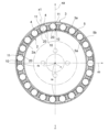
- FIG. 1 is a partial cross-sectional view of a ball bearing according to a first embodiment of the present invention.
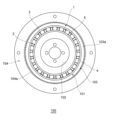
- FIG. 2 is a diagram showing an example of a wave gear device provided with the ball bearing shown in FIG. 1 .
- FIG. 2 is a partial perspective view of a cage in the ball bearing shown in FIG. 1 .
- FIG. 4 is an enlarged view of a pocket of the cage shown in FIG. 3 .
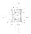
- 5 is a cross-sectional view of the retainer taken along line AA in FIG. 4, which extends radially relative to the pocket axis.
- 2 is an enlarged view showing the vicinity of a rolling element located at the position of the minor axis of an inner ring of the ball bearing shown in FIG.
- FIG. 1 ; 2 is an enlarged view showing the vicinity of a rolling element located at the position of a minor axis of an inner ring in the ball bearing shown in FIG. 1 .
- FIG. 2 is an enlarged view showing the vicinity of a rolling element located at the position of the major axis of an inner ring in the ball bearing shown in FIG. 1 .
- FIG. 5A to 5C are diagrams showing modified examples of the flange portion of the ball bearing according to the first embodiment of the present invention.
- 10A to 10C are diagrams showing other modified examples of the flange portion of the ball bearing according to the first embodiment of the present invention.
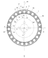
- FIG. 4 is a partial cross-sectional view of a ball bearing according to a second embodiment of the present invention.
- FIG. 12 is an enlarged view showing a pocket of the cage in the ball bearing shown in FIG. 11 .
- 13 is a cross-sectional view of the retainer taken along line DD in FIG. 12 extending radially in the pocket.
- 12 is an enlarged view showing the vicinity of a rolling element located at the major axis position of an inner ring in the ball bearing shown in FIG. 11 .
- FIG. 12 is an enlarged view showing the vicinity of a rolling element located at the major axis position of an inner ring in the ball bearing shown in FIG. 11 .
- FIG. 12 is an enlarged view showing the vicinity of a rolling element located at the position of the minor axis of an inner ring in the ball bearing shown in FIG. 11 .
- FIG. 13A and 13B are diagrams showing modified examples of the flange portion of the ball bearing according to the second embodiment of the present invention.
- 13A and 13B are diagrams showing another modified example of the flange portion of the ball bearing according to the second embodiment of the present invention.
- FIG. 13 is an enlarged view showing the vicinity of the rolling elements and pockets located at the minor axis position of a ball bearing in a strain wave gear device according to a third embodiment of the present invention.
- 20 is a cross-sectional view of the cage and rolling elements taken along line G-G extending radially relative to the pocket axis shown in FIG. 19.
- FIG. 13 is an enlarged view showing the vicinity of the rolling elements and pockets located at the minor axis position of a ball bearing in a wave gear device according to a fourth embodiment of the present invention.
- 22 is a cross-sectional view of the cage and rolling elements taken along line HH extending radially relative to the pocket axis shown in FIG. 21.
- the ball bearing 1 is a partial cross-sectional view of a ball bearing 1 according to a first embodiment of the present invention.
- the ball bearing 1 is shown attached to an elliptical cam 102 of a wave gear device 100, which will be described later.
- the ball bearing 1 is a ball bearing comprising a deformable inner ring 2, a deformable outer ring 3 installed on the outside of the inner ring 2, a plurality of spherical rolling elements 4 provided between the inner ring 2 and the outer ring 3, and a cage 5 in which a plurality of pockets 10, each of which accommodates a plurality of rolling elements 4, are provided at intervals in the circumferential direction.
- Each of the plurality of pockets 10 has a pocket surface 11, which is a surface that extends around a pocket axis x1 extending radially, and a flange portion 20, which is a portion that protrudes from the pocket surface 11 toward the pocket axis x1.
- the pocket surface 11 is adapted to accommodate the rolling elements 4 through a gap
- the flange portion 20 is adapted to contact at least the rolling elements 4 located at the minor radius rb of the inner ring 2 from the radially inner side, or to contact at least the rolling elements 4 located at the major radius ra of the inner ring 2 from the radially outer side.
- the ball bearing 1 will be described in detail below. Note that FIG.
- FIG. 2 shows a wave gear device 100 as an example of a wave gear device provided with a ball bearing 1.
- the ball bearing 1 constitutes a part of a wave generator 101 of the wave gear device 100.
- an elliptical cam 102 is fitted to the inner ring 2 of the ball bearing 1.
- the wave generator 101 is fitted to a cup-shaped flexspline 103, and the flexspline 103 is fitted to a circular spline 104.
- the cam 102 rotates, and the inner ring 2 of the ball bearing 1 rotates together with the cam 102.
- each part on the outer periphery of the outer ring 3 deforms in the radial direction via the rolling elements 4, and at least the part of the outer ring 3 located on the major axis comes into contact with the flexspline 103, and the outer periphery of the flexspline 103 performs wave motion.
- the teeth 103a located in the long axis direction of this wave-moving flexspline 103 mesh with the teeth 104a of the circular spline 104, and due to the difference between the number of teeth of the teeth 103a of the flexspline 103 and the number of teeth of the teeth 104a of the circular spline 104, the circular spline 104 rotates relative to the flexspline 103, and the flexspline 103 or the circular spline 104 rotates at a reduced speed relative to the rotation of the cam 102.
- the inner ring 2 of the ball bearing 1 has a shape similar to that of the inner ring of a conventionally known ball bearing used in a wave gear device, and is a cylindrical or approximately cylindrical flexible or elastic member with the axis x as the central axis or approximately the central axis.
- an elliptical cam 102 is fitted to the inner ring 2, the inner ring 2 is deformed into an elliptical or approximately elliptical cylinder with the axis x as the central axis or approximately the central axis, as shown in FIG. 1.
- the outer peripheral surface 2a which is the surface facing the radial outside of the inner ring 2, is an elliptical or approximately elliptical cylinder surface with the axis x as the central axis or approximately the central axis, and the cross section of the outer peripheral surface 2a perpendicular to the axis x draws an ellipse or approximately ellipse with a major axis ra and a minor axis rb, with the major axis being the major axis xa and the minor axis being the minor axis xb, as shown in FIG. 1.
- the axis x is the axis of the ball bearing 1.
- the outer ring 3 has a similar shape to the outer ring of a conventionally known ball bearing used in a strain wave gear device, and is a cylindrical flexible or elastic member around the axis x as shown in FIG. 1. As shown in FIG. 1, the outer ring 3 has a shape similar to the inner ring 2 in the ball bearing 1. However, the inner ring 2 and the outer ring 3 each have a raceway groove (not shown), and the inner ring 2 and the outer ring 3 are not similar in terms of the raceway groove.
- the retainer 5 is a rigid member having an annular or approximately annular shape with the axis x as its central axis or approximately central axis.
- the retainer 5 is made of, for example, resin.
- the retainer 5 is not limited to being made of resin, and may be made of other materials.
- the retainer 5 has a plurality of pockets 10, and each pocket 10 accommodates a rolling element 4.
- the ball bearing 1 has an odd number of rolling elements 4, and in the illustrated example, the ball bearing 1 has 23 rolling elements 4.
- Each pocket 10 extends along a pocket axis x1 extending along a radial direction perpendicular to the axis x, and penetrates the retainer 5 between the inner peripheral surface 5a and the outer peripheral surface 5b of the retainer 5.
- the inner peripheral surface 5a is the surface facing the radially inward direction of the retainer 5
- the outer peripheral surface 5b is the surface facing the radially outward direction of the retainer 5.
- the diameter of the inner peripheral surface 5a of the retainer 5 is larger than the major axis of the outer peripheral surface 2a of the inner ring 2, and the diameter of the outer peripheral surface 5b of the retainer 5 is smaller than the minor axis of the inner peripheral surface 3a of the outer ring 3 in the ball bearing 1.
- FIG. 3 is a partial perspective view of the retainer 5
- FIG. 4 is an enlarged view of a pocket 10 of the retainer 4
- FIG. 5 is a cross-sectional view of the retainer 5 taken along line A-A extending radially relative to the pocket axis x1 in FIG. 4.
- FIG. 4 shows the pocket 10 as viewed from the outer peripheral surface 5b toward the inner peripheral surface 5a in the direction of the pocket axis x1.
- the retainer 5 has a plurality of claw portions 5c extending along the axis x.
- the claw portions 5c are formed at intervals in the circumferential direction around the axis x, and each pocket 10 is formed between the claw portions 5c adjacent to each other in the circumferential direction.
- each pocket 10 is open on one side in the direction of the axis x.
- an opening 5f that opens the pocket 10 is formed by the surface (opening surface 5e) of the tip 5d facing in the circumferential direction.
- the opening surface 5e continues to the pocket surface 11 and the flange portion 20 on the other side in the axis x direction.
- the pocket axis x1 of each pocket 10 extends, for example, parallel or approximately parallel to the radial direction, and the multiple pockets 10 are arranged, for example, at equal or approximately equal angular intervals around the axis x.
- the pocket surface 11 of each pocket 10 is capable of accommodating the rolling elements 4 with gaps in the radial direction (hereinafter also referred to as the pocket radial direction) perpendicular to the pocket axis x1, and the diameter r1 (see FIG. 4) of the pocket surface 11 is greater than the radius of the rolling elements 4.
- the pocket surface 11 is, for example, a part of a conical surface, a cylindrical surface, or an approximately cylindrical surface with the pocket axis x1 as the central axis or approximately the central axis.
- the pocket surface 11 may be a part of a conical surface, a cylindrical surface, or an approximately cylindrical surface extending along a line close to the pocket axis x1 passing through the axis x or a point in its vicinity.
- the pocket surface 11 can accommodate the rolling elements 4 with gaps over the entire range in the direction of the pocket axis x1.
- the diameter r1a is the diameter r1 of the pocket surface 11 at the end on the flange portion 20 side
- the diameter r1b is the diameter r1 of the pocket surface 11 at the end on the outer peripheral surface 5b side.
- the connection parts 10a and 10b which are the parts where the pocket surface 11 and the pair of open surfaces 5e are connected, respectively, prevent the rolling elements 4 accommodated in the pocket 10 from coming out of the pocket 10 in the direction of the axis x.
- the gap between the connection parts 10a and 10b is smaller than the diameter of the rolling elements 4.
- each pocket 10 is a portion that protrudes inward in the pocket radial direction from the pocket surface 11 and extends around the pocket axis x1, and in this embodiment, has a shape that contacts at least the rolling element 4 located at the minor radius rb of the inner ring 2 from the inside in the radial direction.
- the rolling element 4 located at the minor radius rb of the inner ring 2 is the rolling element 4 that contacts the minor radius rb of the outer circumferential surface 2a of the inner ring 2 in the ball bearing 1, and is the rolling element 4 whose center is located on the minor axis xb of the inner ring 2.
- the flange portion 20 is shaped to prevent the pocket 10 from moving relative to the rolling element 4 when it contacts, for example, the rolling element 4 located at the minor radius rb of the inner ring 2 from the inside in the radial direction, and thereby the cage 5 is supported by the rolling element 4.
- the fact that the pocket 10 cannot move relative to the rolling body 4 means that the position of the rolling body 4 in the pocket 10 does not change, and the rotation of the rolling body 4 is not included in the relative movement of the pocket 10 with respect to the rolling body 4.
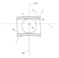
- the diameter (radius r2) of the flange portion 20 in a cross section (cross section B) perpendicular to the pocket axis x1 is the same or approximately the same value as the diameter (radius r3) of the rolling element 4 in a cross section (cross section C) perpendicular to the minor axis xb at a predetermined radial position p1 on the minor axis xb of the rolling element 4 located at the minor radius rb of the inner ring 2 (see FIG.
- FIG. 6 is an enlarged view of the vicinity of the rolling element 4 located at the minor radius rb of the inner ring 2 of the ball bearing 1.
- the cage 5 is omitted in FIG. 6.
- cross sections B and C are the same cross section of the ball bearing 1.
- the flange portion 20 is provided adjacent to the pocket surface 11 on the inner side in the radial direction of the ball bearing 1 with respect to the pocket surface 11, and is provided only at the inner end of the pocket 10 in the direction of the pocket axis x1.
- the flange portion 20 has an inclined surface 21 that is a surface extending around the pocket axis x1 and expands in diameter toward the side in the direction of the pocket axis x1 that contacts the rolling element 4 (the radial outside of the ball bearing 1).
- the flange portion 20 protrudes continuously along the pocket surface 11 around the pocket axis x1.
- FIG. 5 the flange portion 20 is provided adjacent to the pocket surface 11 on the inner side in the radial direction of the ball bearing 1 with respect to the pocket surface 11, and is provided only at the inner end of the pocket 10 in the direction of the pocket axis x1.
- the flange portion 20 has an inclined surface 21 that is a surface extending around the pocket axis x1 and expands in diameter toward the
- the flange portion 20 extends between the respective open surfaces 5e of the pair of claw portions 5c along a circular or approximately circular ring extending around the pocket axis x1, and extends longer than a semicircle. Also, as shown in FIG. 5, the shape of the cross section perpendicular to the extension direction of the flange portion 20 is uniform or approximately uniform.
- the projection range of the inclined surface 21 on the pocket axis x1 in the pocket radial direction is the range s1
- the diameter in cross section B at the radial position p1 within the range s1 is the diameter r2.
- the diameter r3 in cross section C at the radial position p1 on the minor axis xb of the rolling element 4 located at the minor radius rb of the inner ring 2 is the same or approximately the same value as the diameter r2 in the inclined surface 21 of the flange portion 20. Therefore, as shown in FIG.
- the diameter r3 of the peripheral surface of the rolling element 4 located at the minor radius rb of the inner ring 2 is contacted from the inside in the radial direction of the ball bearing 1 by the portion of the diameter r2 of the inclined surface 21 of the flange portion 20.
- the position p1 is, for example, located inside the center of the width of the pocket 10 in the direction of the pocket axis x1. As shown in FIGS. 5 and 6, the diameter in the ball bearing 1 at the radial position p1 is rp1.
- the inclined surface 21 of the flange portion 20 is a tapered surface that describes a straight line or an approximately straight line in a cross section including the pocket axis x1, as shown in FIG. 5, for example.
- the inclined surface 21 is not limited to such a tapered surface, and may be a surface of another shape as long as it is a surface that contacts at least the rolling element 4 located at the minor radius rb of the inner ring 2 from the inside in the radial direction of the ball bearing 1 at the position of radius r2 of the radial position p1, as described above.
- the inclined surface 21 may be a surface that describes a convex arc or arc toward the pocket axis x1 side in a cross section including the pocket axis x1, a surface that describes a concave arc or arc toward the opposite side to the pocket axis x1 side, or a surface that describes another curve.
- the inclined surface 21 may also be a surface that describes a line that is a combination of a curve and a straight line in a cross section including the pocket axis x1.
- each pocket 10 may have a recess 12 on the inside in the direction of the pocket axis x1 of the flange portion 20.
- the recess 12 extends between the inner end (inner end 21a) of the inclined surface 21 of the flange portion 20 in the direction of the pocket axis x1 and the inner peripheral surface 5a of the retainer 5, and is, for example, a part of a conical surface, a cylindrical surface, or a substantially cylindrical surface with the pocket axis x1 as the central axis or substantially central axis.
- the form of the recess 12 is not limited to this form.
- the recess 12 may be, for example, a part of a conical surface, a cylindrical surface, or a substantially cylindrical surface extending along a line close to the pocket axis x1 passing through the axis x or a point in its vicinity.
- Figure 7 is an enlarged view of the vicinity of the rolling element 4 located at the minor radius rb of the inner ring 2 in the ball bearing 1
- Figure 8 is an enlarged view of the vicinity of the rolling element 4 located at the major radius ra of the inner ring 2 in the ball bearing 1.
- each rolling element 4 describes an elliptical orbit centered on the axis x.
- Each rolling element 4 is closest to the axis x in the radial direction at the position of the minor radius rb of the inner ring 2.
- each rolling element 4 moves away from the axis x as it approaches the position of the major radius ra, and each rolling element 4 is farthest from the axis x in the radial direction at the position of the major radius ra of the inner ring 2.
- the radial position of each rolling element 4 moves closer to the axis x as it approaches the position of the minor radius rb.
- the rolling elements 4 repeat this radial movement while moving around the outer peripheral surface 2a of the inner ring 2.
- the cage 5 is a member having a rigidity in an annular shape, and each pocket 10 of the cage 5 describes a circular orbit centered on the axis x.
- the radial position of each pocket 10 of the cage 5 from the axis x remains constant or almost constant as the cage 5 rotates. Therefore, each rolling element 4 revolving on the outer peripheral surface 2a of the inner ring 2 moves relative to the pocket 10 in the direction of the pocket axis x1 within the pocket 10 in which it is housed.
- each rolling element 4 moves relative to the pocket 10 in the direction of the pocket axis x1 toward the innermost side in relation to the pocket 10, and at the position of the major radius ra of the inner ring 2, it moves relative to the pocket 10 in the direction of the pocket axis x1 toward the outermost side in relation to the pocket 10.
- the rolling element 4 which is located at the minor radius rb of the inner ring 2 and has moved inward most in relation to the pocket 10 in the direction of the pocket axis x1, comes into contact with the inclined surface 21 of the flange portion 20 of the pocket 10. Specifically, a portion of the inclined surface 21 of radius r2 on cross section B (C) at position p1 radially spaced by radius rp1 from the axis x comes into contact with a portion of the rolling element 4 of radius r3 on cross section C (B) at position p1 radially spaced by radius rp1 from the axis x. Due to this contact between the flange portion 20 and the rolling element 4, the cage 5 is supported by the rolling element 4 and cannot move relative to the rolling element 4 in the pocket radial direction or radially outward of the ball bearing 1.
- the cage 5 is not restricted in its movement in the direction of the minor axis xb to the other side (left side in FIG. 1) by the rolling element 4 that it contacts at a position on the minor axis xb on one side (right side in FIG. 1), but is substantially restricted in its relative movement to the other side (left side in FIG. 1) in the direction of the minor axis xb by at least one of the two rolling elements 4 located in the vicinity of the position of the minor axis xb on the other side (left side in FIG. 1).
- the movement of the cage 5 in the ball bearing 1 is restricted by contact between one rolling element 4 located at the position of the minor radius rb of the inner ring 2 and one or two rolling elements 4 located in the vicinity of the position of the minor radius rb of the inner ring 2, and the flange portions 20 of one pocket 10 located on the minor axis xb of the inner ring 2 and one or two pockets 10 located in the vicinity of the minor axis xb of the inner ring 2.
- each rolling element 4 moves outwardly relative to the pocket 10 in which it is housed in the direction of the pocket axis x1 at the position of the long radius ra of the inner ring 2.
- the rolling element 4 located at the position of the long radius ra of the inner ring 2 moves to a position furthest from the inclined surface 21 of the flange portion 20 of the pocket 10.
- the retainer 5 is supported only by the rolling elements 4 located in the vicinity of the minor radius rb of the inner ring 2. Therefore, when the ball bearing 1 is rotated and in use, the generation of forces that deform the retainer 5 can be suppressed. Also, in the ball bearing 1, as shown in FIG. 7, the flange portion 20 and the rolling elements 4 come into contact at the portion of radius r2 of the inclined surface 21 and the portion of radius r3 of the rolling elements 4 in cross section B (C) at position p1 of the same radius rp1. Therefore, no force that deforms the retainer 5 is generated by contact between the flange portion 20 and the rolling elements 4. Therefore, in the ball bearing 1, the retainer 5 is not deformed when in use.
- the position of the flange portion 20 that contacts the rolling element 4 located at the minor radius rb of the inner ring 2 is the position of the radius of the inclined surface 21 in the cross section at a position radially outside the position p1 of the radius rp1
- a force that deforms the retainer 5 toward the axis x at the position of the minor axis xb is generated in the retainer 5.
- the retainer 5 bends at the position of the major axis xa, its curvature increases, and the circumferential spacing of the pockets 10 on the major axis xa narrows.
- the circumferential width at the position of the inclined surface 21 of the flange portion 20 located radially inward narrows.
- the rolling element 4 located at the major radius ra of the inner ring 2 moves outward most relative to the pocket 10 in which it is accommodated in the direction of the pocket axis x1, and moves to a position furthest from the inclined surface 21 of the flange portion 20 of the pocket 10.
- the pocket 10 on the long axis xa can be prevented or suppressed from being pressed against the rolling element 5, further deformation of the retainer 5 can be prevented or suppressed, and damage to the retainer 5 can be prevented or suppressed.
- the retainer 5 when the ball bearing 1 is in use, the retainer 5 does not come into contact with the inner ring 2 or the outer ring 3, which prevents an increase in the torque resistance of the ball bearing 1. In this respect, deformation of the retainer 5 in use is avoided or suppressed, and damage to the retainer 5 is avoided or suppressed.
- the flange portion 20 of the pocket 10 of the ball bearing 1 can restrict the movement of the retainer 5 in the ball bearing 1, and can prevent or reduce vibration of the retainer 5 in the ball bearing 1.
- the pocket 10 of the ball bearing 1 can suppress deformation of the retainer 5.
- the two rolling elements 4 located near the position of the minor radius rb of the other inner ring 2 on the orbit of the rolling element 4 act in a manner similar to the rolling element 4 located at the position of the minor radius rb of the inner ring 2.
- at least one of the two rolling elements 4 located near the position of the minor radius rb of the other inner ring 2 on the orbit of the rolling element 4 may act in a manner similar to the rolling element 4 located at the position of the minor radius rb of the inner ring 2.
- the rolling element 4 located at the position of the minor radius rb of one inner ring 2 on the orbit of the rolling element 4 and at least one of the two rolling elements 4 located near the position of the minor radius rb of the other inner ring 2 on the orbit of the rolling element 4 may be in contact with the flange portion 20 of the pocket 10.
- the ball bearing 1 according to the first embodiment of the present invention can prevent deformation of the retainer 5 while preventing vibration of the retainer 5 in the strain wave gear device 100.
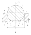
- FIG. 9 is a diagram showing a modified example of the flange portion 20 of the ball bearing 1, and is an enlarged view of the vicinity of the rolling element 4 located at the minor radius rb of the inner ring 2 of the ball bearing 1.
- the flange portion 20 of the ball bearing 1 may have a step surface 22 instead of the inclined surface 21 described above.
- the step surface 22 has an annular surface 22a that is an annular surface around the pocket axis x1 that extends from the inner end of the pocket surface 11 in the pocket axis x1 direction to the pocket radially inward, and a cylindrical surface 22b that extends along the pocket axis x1 that extends from the inner end of the annular surface 22a in the pocket radial direction to the inner peripheral surface 5a in the pocket axis x1 direction.
- the annular surface 22a is a surface extending along a plane perpendicular to the pocket axis x1, and is a surface parallel or approximately parallel to the plane perpendicular to the pocket axis x1, as shown in FIG. 9, for example, and is a part of a torus or approximately torus surface with the pocket axis x1 as the central axis or approximately central axis.
- the cylindrical surface 22b is a part of a cylindrical surface extending along the pocket axis x1, and is, for example, a part of a conical surface, a cylindrical surface, or an approximately cylindrical surface with the pocket axis x1 as the central axis or approximately central axis.
- the cylindrical surface 22b may be, for example, a part of a conical surface, a cylindrical surface, or an approximately cylindrical surface extending along a line close to the pocket axis x1 passing through the axis x or a point in its vicinity.
- the annular surface 22a and the cylindrical surface 22b extend continuously between the connection portion 10a and the connection portion 10b (see FIG. 4).
- connection portion 22c which is the portion where the annular surface 22a and the cylindrical surface 22b are connected, is located on the cross section B at the position p1 of the above-mentioned radius rp1, and extends on a ring centered on the pocket axis x1.
- the radius of the connection portion 22c in the pocket radial direction is radius r2. Therefore, the step surface 22 of the flange portion 20 contacts at least the rolling elements 4 located at the position of the minor radius rb of the inner ring 2 at the connection portion 22c, similar to the inclined surface 21 of the flange portion 20 described above, and the cage 5 is supported. Therefore, the step surface 22 of the flange portion 20 in this modified example also acts in the same way as the inclined surface 21 of the flange portion 20 described above.
- FIG. 10 is a diagram showing another modified example of the flange portion 20 of the ball bearing 1, showing the pocket 10 viewed from the outer peripheral surface 5b side toward the inner peripheral surface 5a side in the direction of the pocket axis x1.
- the flange portion 20 may protrude intermittently along the pocket surface 11 around the pocket axis x1.
- the flange portion 20 may be formed by providing a plurality of flange pieces 20a at intervals around the pocket axis x1.
- the shape of the cross section including the pocket axis x1 of each flange piece 20a is the same as the shape of the cross section including the pocket axis x1 of the flange portion 20 described above (see FIGS. 5 and 9).
- the inclined surface 21 or the step surface 22 of each flange piece 20a overlaps with the inclined surface 21 or the step surface 22 at the corresponding position of the flange portion 20 described above (see FIG. 4).
- the number of flange pieces 20a is not limited to the number shown in the figure.
- the ball bearing 6 according to the second embodiment of the present invention has a retainer 7 that is different from the retainer 5 of the ball bearing 1 according to the first embodiment of the present invention described above.
- the retainer 7 of the ball bearing 6 differs from the retainer 5 described above in that it has a pocket 13 that is different from the pocket 10 of the ball bearing 1.
- components that have the same configuration or similar function as the ball bearing 1 described above will be assigned the same reference numerals as those in the ball bearing 1 and will not be described, and only components that differ from the ball bearing 1 will be described.
- FIG. 11 is a partial cross-sectional view of a ball bearing 6 according to a second embodiment of the present invention.
- the ball bearing 6 is shown as viewed from the front, with the inner ring 2, outer ring 3, and cage 7 cut away.
- FIG. 12 is an enlarged view of the pocket 13 of the cage 7, and
- FIG. 13 is a cross-sectional view taken along line D-D extending in the radial direction of the pocket in FIG. 12.
- the ball bearing 6 is shown in the form in which it is attached to the elliptical cam 102 of the strain wave gear device 100, as in FIG. 1.
- FIG. 12 shows the pocket 13 when viewed from the inner circumferential surface 5a side toward the outer circumferential surface 5b side in the direction of the pocket axis x1.
- each pocket 13 of the cage 7 of the ball bearing 6 has a flange portion 23 for supporting the cage 7 like the flange portion 20 of the pocket 10 described above.
- the flange portion 23 is designed to contact at least the rolling element 4 located at the position of the major radius ra of the inner ring 2 from the outside in the radial direction.
- the rolling element 4 located at the position of the major radius ra of the inner ring 2 is the rolling element 4 that contacts the outer peripheral surface 2a of the inner ring 2 at the position of the major radius ra in the ball bearing 6, and is the rolling element 4 whose center is located on the major axis xa of the inner ring 2.
- each pocket 13 in the retainer 7 of the ball bearing 6 are formed between adjacent claw portions 5c in the circumferential direction, similar to the multiple pockets 10 in the retainer 5 described above.
- Each pocket 13 extends along a pocket axis x1 and penetrates the retainer 7 between the inner peripheral surface 5a and the outer peripheral surface 5b of the retainer 7.
- the pocket axis x1 of each pocket 13 extends, for example, parallel or approximately parallel to the radial direction, and the multiple pockets 13 are provided, for example, at equal or approximately equal angular intervals around the axis x.
- each pocket 13 has a pocket surface 14 similar to the pocket surface 11 of the above-mentioned pocket 10.
- the diameter r1 of the pocket surface 14 (see Figure 12) is larger than the radius of the rolling element 4.
- the pocket surface 14 is, for example, a part of a conical surface, a cylindrical surface, or a substantially cylindrical surface with the pocket axis x1 as the central axis or substantially central axis.
- the pocket surface 14 may be a part of a conical surface, a cylindrical surface, or a substantially cylindrical surface extending along a line close to the pocket axis x1 passing through the axis x or a point nearby it.
- diameter r1a is diameter r1 of pocket surface 14 at the end on the flange portion 23 side
- diameter r1c is diameter r1 of pocket surface 14 at the end on the inner peripheral surface 5a side.
- flange portion 23 of each pocket 13 is a portion that protrudes inward in the pocket radial direction from pocket surface 14 and extends around pocket axis x1.
- flange portion 23 is shaped to prevent pocket 13 from moving relative to rolling element 4 when it comes into contact with rolling element 4 located at the major radius ra of inner ring 2 from the outside in the radial direction, and thus retainer 7 is supported by rolling element 4.
- the diameter (radius r4) of the flange portion 23 in a cross section (cross section E) perpendicular to the pocket axis x1 is the same or approximately the same value as the diameter (radius r5) of the rolling element 4 in a cross section (cross section F) perpendicular to the major axis xa at a predetermined radial position p2 on the major axis xa of the rolling element 4 located at the major axis ra of the inner ring 2 (see FIG.
- FIG. 14 is an enlarged view of the vicinity of the rolling element 4 located at the major axis ra of the inner ring 2 of the ball bearing 6.
- the cage 7 is omitted in FIG. 14.
- cross sections E and F are the same cross section of the ball bearing 6.
- the flange portion 23 is provided adjacent to the pocket surface 14 on the outer side in the radial direction of the ball bearing 6 with respect to the pocket surface 14, and is provided only at the outer end of the pocket 13 in the direction of the pocket axis x1.
- the flange portion 23 has an inclined surface 24 that is a surface extending around the pocket axis x1 and expands in diameter toward the side in the direction of the pocket axis x1 that contacts the rolling element 4 (the radial inner side of the ball bearing 6).
- the flange portion 23 also protrudes continuously along the pocket surface 14 around the pocket axis x1.
- the flange portion 23 extends between the respective open surfaces 5e of the pair of claw portions 5c along a circular or approximately circular ring extending around the pocket axis x1, and extends longer than a semicircle. Also, as shown in FIG. 13, the shape of the cross section perpendicular to the extension direction of the flange portion 23 is uniform or approximately uniform.
- the projection range of the inclined surface 24 on the pocket axis x1 in the pocket radial direction is the range s2
- the diameter in the cross section E at the radial position p2 within the range s2 is the diameter r4.
- the diameter r5 in the cross section F at the radial position p2 on the major axis xa of the rolling element 4 located at the position of the major radius ra of the inner ring 2 is the same or approximately the same value as the diameter r4 in the inclined surface 24 of the flange portion 23. Therefore, as shown in FIG.
- the diameter r4 part of the inclined surface 24 of the flange portion 23 contacts the part of the diameter r5 of the circumferential surface of the rolling element 4 located at the position of the major radius ra of the inner ring 2 from the outside in the radial direction of the ball bearing 6.
- the position p2 is, for example, outside the center of the width of the pocket 13 in the direction of the pocket axis x1. Note that, as shown in FIGS. 13 and 14, the diameter in the ball bearing 6 at the radial position p3 is rp2.
- the inclined surface 24 of the flange portion 23 is a tapered surface that describes a straight line or an approximately straight line in a cross section including the pocket axis x1, as shown in FIG. 13, for example.
- the inclined surface 24 is not limited to such a tapered surface, and may be a surface of another shape as long as it is a surface that contacts at least the rolling element 4 located at the position of the major radius ra of the inner ring 2 from the outside in the radial direction of the ball bearing 6 at the position of radius r4 of the radial position p2 as described above.
- the inclined surface 24 may be a surface that describes a convex arc or arc toward the pocket axis x1 side in a cross section including the pocket axis x1, a surface that describes a concave arc or arc on the opposite side to the pocket axis x1 side, or a surface that describes another curve.
- the inclined surface 24 may also be a surface that describes a line that is a combination of a curve and a straight line in a cross section including the pocket axis x1.
- each pocket 13 may have a clearance 15 on the outside in the direction of the pocket axis x1 of the flange portion 23.
- the clearance 15 extends between the outer end (outer end 24a) of the inclined surface 24 of the flange portion 23 in the direction of the pocket axis x1 and the outer peripheral surface 5b of the retainer 7, and is, for example, a part of a conical surface, a cylindrical surface, or a substantially cylindrical surface with the pocket axis x1 as the central axis or substantially central axis.
- the form of the clearance 15 is not limited to this form.
- the clearance 15 may be, for example, a part of a conical surface, a circle, or a substantially cylindrical surface extending along a line close to the pocket axis x1 passing through the axis x or a point nearby it.
- Figure 15 is an enlarged view of the vicinity of the rolling element 4 located at the major radius ra of the inner ring 2 in the ball bearing 6
- Figure 16 is an enlarged view of the vicinity of the rolling element 4 located at the minor radius rb of the inner ring 2 in the ball bearing 6.
- each rolling element 4 moving around the outer circumferential surface 2a of the inner ring 2 moves relative to the pocket 13 in the direction of the pocket axis x1 within the pocket 13 in which it is housed.
- Each rolling element 4 moves inwardly most relative to the pocket 13 in the direction of the pocket axis x1 at the position of the minor radius rb of the inner ring 2, and moves inwardly most relative to the pocket 13 in the direction of the pocket axis x1 at the position of the major radius ra of the inner ring 2.
- the rolling element 4 which is located at the major radius ra of the inner ring 2 and has moved outward most relative to the pocket 13 in the direction of the pocket axis x1, comes into contact with the inclined surface 24 of the flange portion 23 of the pocket 13. Specifically, a portion of the inclined surface 24 of radius r4 on the cross section E (F) at position p2 radially spaced by radius rp2 from the axis x comes into contact with a portion of the rolling element 4 of radius r5 on the cross section F (E) at position p2 radially spaced by radius rp2 from the axis x. Due to this contact between the flange portion 23 and the rolling element 4, the cage 7 is supported by the rolling element 4 and cannot move relative to the rolling element 4 in the pocket radial direction or radially inward of the ball bearing 6.
- the cage 7 is not restricted in its relative movement to one side (upper side in FIG. 11 ) in the direction of the major axis xa by the rolling element 4 that it comes into contact with at one position on the major axis xa (upper side in FIG. 11 ), but is substantially restricted in its relative movement to one side (upper side in FIG. 11 ) in the direction of the major axis xa by at least one of the two rolling elements 4 located in the vicinity of the position of the major axis xa on the other side (lower side in FIG. 11 ).
- the cage 7 is restricted in its movement in the ball bearing 6 by contact with one rolling element 4 located at the position of the major radius ra of the inner ring 2 and one or two rolling elements 4 located in the vicinity of the position of the major radius ra of the inner ring 2, and with one pocket 13 located on the major axis xa of the inner ring 2 and the flange portions 23 of one or two rolling elements 4 located in the vicinity of the major axis xa of the inner ring 2.
- each rolling element 4 moves inwardly relative to the pocket 13 in which it is housed in the direction of the pocket axis x1 at the position of the minor radius rb of the inner ring 2.
- the rolling element 4 located at the position of the minor radius rb of the inner ring 2 moves to a position furthest from the inclined surface 24 of the flange portion 23 of the pocket 13.
- the retainer 7 is supported only by the rolling elements 4 located in the vicinity of the major radius ra of the inner ring 2. This makes it possible to suppress the generation of forces that deform the retainer 7 when the ball bearing 6 is in use. Also, in the ball bearing 6, as shown in FIG. 14, the flange portion 23 and the rolling elements 4 come into contact at the portion of radius r4 of the inclined surface 24 and the portion of radius r5 of the rolling elements 4 in cross section E (F) at position p2 of the same radius rp2. This means that no force that deforms the retainer 7 is generated by contact between the flange portion 23 and the rolling elements 4. Therefore, in the ball bearing 6, the retainer 7 is not deformed when in use.
- the position of the flange portion 23 that contacts the rolling elements 4 located at the major radius ra of the inner ring 2 is at the position of the radius of the inclined surface 24 in the cross section at a position radially inward from the position p2 of the radius rp2, a force that deforms the retainer 7 toward the axis x at the position of the major axis xa is generated in the retainer 7.
- the retainer 7 bends at the position of the minor axis xb, its curvature increases, and the circumferential spacing of the pockets 13 on the minor axis xb narrows.
- the circumferential width of the portion of the pocket surface 14 located radially inward narrows.
- the rolling elements 4 located at the minor radius rb of the inner ring 2 move relative to the pocket 13 in which they are accommodated, in the direction of the pocket axis x1, toward the innermost position. Therefore, even if the retainer 7 is deformed due to contact between the rolling elements 4 on the long axis xa and the flange portion 23 as described above, the diameter of the cylindrical portion 14 of the pocket 13 may be adjusted to prevent or suppress the pocket 13 on the short axis xb from being pressed against the rolling elements 7. This adjustment can prevent or suppress further deformation of the retainer 7, and can prevent or suppress damage to the retainer 7.
- the retainer 7 when the ball bearing 6 is in use, the retainer 7 does not come into contact with the inner ring 2 or the outer ring 3, which prevents an increase in the torque resistance of the ball bearing 6. In this respect, deformation of the retainer 7 in use is avoided or suppressed, and damage to the retainer 7 is avoided or suppressed.
- the flange portion 23 of the pocket 13 of the ball bearing 6 can restrict the movement of the retainer 7 in the ball bearing 6, and can prevent or reduce vibration of the retainer 7 in the ball bearing 6.
- the pocket 13 of the ball bearing 6 can suppress deformation of the retainer 7.
- the two rolling elements 4 located near the position of the major radius ra of the other inner ring 2 on the orbit of the rolling element 4 act in a manner similar to the rolling element 4 located at the position of the major radius ra of the inner ring 2.
- at least one of the two rolling elements 4 located near the position of the major radius ra of the other inner ring 2 on the orbit of the rolling element 4 may act in a manner similar to the rolling element 4 located at the position of the major radius ra of the inner ring 2.
- the rolling element 4 located at the position of the major radius ra of one inner ring 2 on the orbit of the rolling element 4 and at least one of the two rolling elements 4 located near the position of the major radius ra of the other inner ring 2 on the orbit of the rolling element 4 may come into contact with the flange portion 23 of the pocket 13.
- the ball bearing 6 according to the second embodiment of the present invention can prevent the retainer 7 from vibrating while preventing deformation of the retainer 7 in the strain wave gear device 100.
- FIG. 17 is a diagram showing a modified example of the flange portion 23 of the ball bearing 6, and is an enlarged view of the vicinity of the rolling element 4 located at the position of the major axis ra of the inner ring 2 of the ball bearing 6.
- the flange portion 23 of the ball bearing 6 may have a step surface 25 instead of the inclined surface 24 described above.
- the step surface 25 has an annular surface 25a that is an annular surface around the pocket axis x1 that extends from the outer end of the pocket surface 14 in the pocket axis x1 direction to the inner side in the pocket radial direction, and a cylindrical surface 25b that extends along the pocket axis x1 that extends from the inner end of the annular surface 25a in the pocket radial direction to the outer circumferential surface 5b in the pocket axis x1 direction.
- the annular surface 25a is a surface extending along a plane perpendicular to the pocket axis x1, and is a surface parallel or approximately parallel to the plane perpendicular to the pocket axis x1, as shown in FIG. 17, for example, and is a part of a torus or approximately torus surface with the pocket axis x1 as the central axis or approximately central axis.
- the cylindrical surface 25b is a part of a cylindrical surface extending along the pocket axis x1, and is, for example, a part of a conical surface, a cylindrical surface, or an approximately cylindrical surface with the pocket axis x1 as the central axis or approximately central axis.
- the cylindrical surface 25b may be, for example, a part of a conical surface, a cylindrical surface, or an approximately cylindrical surface extending along a line close to the pocket axis x1 passing through the axis x or a point in its vicinity.
- the annular surface 25a and the cylindrical surface 25b extend continuously between the connection portion 10a and the connection portion 10b (see FIG. 12).
- connection portion 25c which is the portion where the annular surface 25a and the cylindrical surface 25b are connected, is located on the cross section E at the position p2 of the above-mentioned radius rp2, and extends on a ring centered on the pocket axis x1.
- the radius of the connection portion 25c in the pocket radial direction is radius r4. Therefore, the step surface 25 of the flange portion 23 contacts at least the rolling elements 4 located at the position of the major radius ra of the inner ring 2 at the connection portion 25c, similar to the inclined surface 24 of the flange portion 23 described above, and the cage 7 is supported. Therefore, the step surface 25 of the flange portion 23 in this modified example also acts in the same way as the inclined surface 24 of the flange portion 23 described above.
- FIG. 18 is a diagram showing another modified example of the flange portion 23 of the ball bearing 6, showing the pocket 13 viewed from the inner peripheral surface 5a side toward the outer peripheral surface 5b side in the direction of the pocket axis x1.
- the flange portion 23 may protrude intermittently along the pocket surface 14 around the pocket axis x1.
- the flange portion 23 may be formed by providing a plurality of flange pieces 23a at intervals around the pocket axis x1.
- the shape of the cross section including the pocket axis x1 of each flange piece 23a is the same as the shape of the cross section including the pocket axis x1 of the flange portion 23 described above (see FIGS. 13 and 17).
- the inclined surface 24 or the step surface 25 of each flange piece 23a overlaps with the inclined surface 24 or the step surface 25 at the corresponding position of the flange portion 23 described above (see FIG. 12).
- the number of flange pieces 23a is not limited to the number shown in the figure.
- the ball bearing 1A according to the third embodiment of the present invention has a retainer 5A that is different from the retainer 5 of the ball bearing 1 according to the first embodiment of the present invention described above.
- the retainer 5A of the ball bearing 1A differs from the retainer 5 described above in that it has a pocket 16 that is different from the pocket 10 of the ball bearing 1.
- components that have the same configuration or similar function as the above-mentioned ball bearing 1 are given the same reference numerals as those in the ball bearing 1 and their description is omitted, and components that differ from the ball bearing 1 will be described.
- the pocket 16 of the retainer 5A has a flange portion 26 that contacts at least the rolling elements 4 located at the position of the minor radius rb of the inner ring 2 from the radially inner side, like the flange portion 20 of the pocket 10 described above.
- the flange portion 26 is configured to prevent the rolling elements 4 from moving relative to the pocket 16, thereby supporting the retainer 5A on the rolling elements 4.
- the flange portion 26, together with the pocket surface 11 of the pocket 16 is configured to prevent the pocket 16 from moving relative to the rolling elements 4, thereby supporting the retainer 5A on the rolling elements 4.
- Figure 19 is an enlarged view of the rolling element 4 and pocket 16 located at the minor radius rb of ball bearing 1A in strain wave gear device 100
- Figure 20 is a cross-sectional view taken along line G-G extending radially relative to pocket axis x1 in Figure 19.
- Figure 19 shows the rolling element 4 and pocket 16 as viewed from the outer peripheral surface 5b toward the inner peripheral surface 5a in the direction of pocket axis x1.
- the flange portion 26 like the flange portion 20 in the first embodiment of the present invention, protrudes radially inward from the pocket surface 11, is adjacent to the inside of the cylindrical portion 11 in the direction of the pocket axis x1, and is provided only at the inner end of the pocket 16 in the direction of the pocket axis x1. Also, like the flange portion 20 described above, the flange portion 26 extends continuously along the pocket surface 11 around the pocket axis x1. However, as shown in FIG. 19, the flange portion 26 does not extend to the connection portion 10a and the connection portion 10b. Also, like the flange portion 20, the flange portion 26 has an inclined surface 27.
- the inclined surface 27 has a shape that contacts at least the rolling element 4 located at the position of the minor radius rb of the inner ring 2 from the radial inside, but unlike the inclined surface 21, it has a shape that the rolling element 4 contacts the pocket surface 11 when it comes into contact with the rolling element 4.
- the inclined surface 27 may be configured to contact the entire surface of the rolling element 4 located at least at the position of the minor radius rb of the inner ring 2, or may be configured to contact only a portion of the rolling element 4.
- the pocket surface 11 is configured to contact only a portion of the rolling element 4 located at least at the position of the minor radius rb of the inner ring 2.
- the rolling element 4 located near the position of the minor radius rb is substantially rendered immovable relative to the pocket 16, and the retainer 5A is supported by the rolling element 4 and is rendered immovable relative to the rolling element 4 in the pocket radial direction and radially outward of the ball bearing 1A.
- the movement of the retainer 5A in the ball bearing 1A is restricted by contact between at least one of the rolling elements 4 located at the minor radius rb of the inner ring 2 and the two rolling elements 4 located near the minor radius rb of the inner ring 2, and the flange portion 26 and pocket surface 11 of one pocket 16 located on the minor axis xb of the inner ring 2 and one or two pockets 10 located near the minor axis xb of the inner ring 2.
- the movement of the retainer 5A in the ball bearing 1A is restricted by contact between the two or three rolling elements 4 that move sequentially to the position of the minor radius rb of the inner ring 2 and near the minor axis rb of the inner ring 2, and the flange portion 26 and pocket surface 11 of each of the two or three pockets 16 that move sequentially to the minor axis xb of the inner ring 2 and near the minor axis xb of the inner ring 2.
- the flange portion 26 and pocket surface 11 of ball bearing 1A act in the same way as the flange portion 20 of ball bearing 1, and ball bearing 1A provides the same effects as ball bearing 1.
- the flange portion 26 and pocket surface 11 of pocket 16 can restrict the movement of retainer 5A in ball bearing 1A, and can prevent or reduce vibration of retainer 5A in ball bearing 1A.
- pocket 16 of ball bearing 1A can suppress deformation of retainer 5A.
- the two rolling elements 4 located near the position of the minor radius rb of the other inner ring 2 on the orbit of the rolling element 4 act in a manner similar to the rolling element 4 located at the position of the minor radius rb of the inner ring 2.
- at least one of the two rolling elements 4 located near the position of the minor radius rb of the other inner ring 2 on the orbit of the rolling element 4 may act in a manner similar to the rolling element 4 located at the position of the minor radius rb of the inner ring 2.
- the rolling element 4 located at the position of the minor radius rb of one inner ring 2 on the orbit of the rolling element 4 and at least one of the two rolling elements 4 located near the position of the minor radius rb of the other inner ring 2 on the orbit of the rolling element 4 may be in contact with the flange portion 26 of the pocket 16 and the pocket surface 11.
- the ball bearing 1A according to the third embodiment of the present invention can prevent deformation of the retainer 5A while preventing vibration of the retainer 5A in the strain wave gear device 100.
- the flange portion 26 can be modified in the same manner as the flange portion 20 of the ball bearing 1 according to the first embodiment of the present invention. That is, the flange portion 26 may have a step surface similar to the step surface 22, rather than an inclined surface 27, as shown in FIG. 9. The flange portion 26 may also protrude intermittently along the pocket surface 11 around the pocket axis x1, as shown in FIG. 10.
- the ball bearing 6A according to the fourth embodiment of the present invention has a retainer 7A that is different from the retainer 7 of the ball bearing 6 according to the second embodiment of the present invention described above.
- the retainer 7A of the ball bearing 6A differs from the retainer 7 described above in that it has a pocket 17 that is different from the pocket 13 of the ball bearing 6.
- components that have the same configuration or similar function as the ball bearing 6 described above will be assigned the same reference numerals as those in the ball bearing 6 and will not be described, and components that differ from the ball bearing 6 will be described.
- the pocket 17 of the retainer 7A has a flange portion 28 that contacts from the radial outside with at least the rolling elements 4 located at the position of the major radius ra of the inner ring 2, like the flange portion 23 of the pocket 13 described above.
- the flange portion 28 is configured to prevent the rolling elements 4 from moving relative to the pocket 17, thereby supporting the retainer 7A on the rolling elements 4.
- the flange portion 28 when in contact with at least the rolling elements 4 located at the position of the major radius ra of the inner ring 2, the flange portion 28, together with the pocket surface 14 of the pocket 17, prevents the pocket 17 from moving relative to the rolling elements 4, thereby supporting the retainer 7A on the rolling elements 4.
- Figure 21 is an enlarged view of the rolling element 4 and pocket 17 located at the major axis ra of the ball bearing 6A in the strain wave gear device 100
- Figure 22 is a cross-sectional view taken along line H-H extending radially relative to the pocket axis x1 in Figure 21. Note that Figure 21 shows the rolling element 4 and pocket 17 as viewed from the inner circumferential surface 5a toward the outer circumferential surface 5b in the direction of the pocket axis x1.
- the flange portion 28 like the flange portion 23 in the second embodiment of the present invention described above, protrudes from the pocket surface 14 in the radial direction of the pocket inward, is adjacent to the outer side of the cylindrical portion 14 in the direction of the pocket axis x1, and is provided only at the outer end of the pocket 17 in the direction of the pocket axis x. Also, like the flange portion 23 described above, the flange portion 28 extends continuously along the pocket surface 14 around the pocket axis x1. However, as shown in FIG. 21, the flange portion 28 does not extend to the connection portion 10a and the connection portion 10b. Also, like the flange portion 23, the flange portion 27 has an inclined surface 29.
- the inclined surface 29 has a shape that contacts at least the rolling element 4 located at the position of the major radius ra of the inner ring 2 from the radial outside, but unlike the inclined surface 24, it has a shape that the rolling element 4 contacts the pocket surface 14 when it comes into contact with the rolling element 4.
- the inclined surface 29 may be configured to contact the entire surface of the rolling element 4 located at least at the position of the major radius ra of the inner ring 2, or may be configured to contact only a portion of the rolling element 4.
- the pocket surface 14 is configured to contact only a portion of the rolling element 4 located at least at the position of the major radius ra of the inner ring 2.
- the rolling element 4 located near the position of the major radius ra is substantially rendered immovable relative to the pocket 17, and the retainer 7A is supported by the rolling element 4 and is rendered immovable relative to the rolling element 4 in the pocket radial direction and radially inward of the ball bearing 6A.
- the movement of the retainer 7A in the ball bearing 6A is restricted by contact between at least one of the rolling elements 4 located at the major axis ra of the inner ring 2 and the two rolling elements 4 located near the major axis ra of the inner ring 2, and the flange portion 28 and pocket surface 14 of one pocket 17 located on the major axis xa of the inner ring 2 and one or two pockets 17 located near the major axis xa of the inner ring 2.
- the movement of the retainer 7A in the ball bearing 6A is restricted by contact between the two or three rolling elements 4 that move sequentially to the major axis ra of the inner ring 2 and near the major axis ra of the inner ring 2, and the flange portion 28 and pocket surface 14 of each of the two or three pockets 17 that move sequentially on the major axis xa of the inner ring 2 and near the major axis xa of the inner ring 2.
- the flange portion 28 and pocket surface 14 of the ball bearing 6A act in the same way as the flange portion 26 of the ball bearing 6, and the ball bearing 6A provides the same effects as the ball bearing 6.
- the flange portion 28 and pocket surface 14 of the pocket 17 can restrict the movement of the retainer 7A in the ball bearing 6A, and can prevent or reduce vibration of the retainer 7A in the ball bearing 6A.
- the pocket 17 of the ball bearing 6A can suppress deformation of the retainer 7A.
- the two rolling elements 4 located near the position of the major radius ra of the other inner ring 2 on the orbit of the rolling element 4 act in a manner similar to the rolling element 4 located at the position of the major radius ra of the inner ring 2.
- at least one of the two rolling elements 4 located near the position of the major radius ra of the other inner ring 2 on the orbit of the rolling element 4 may act in a manner similar to the rolling element 4 located at the position of the major radius ra of the inner ring 2.
- the rolling element 4 located at the position of the major radius ra of one inner ring 2 on the orbit of the rolling element 4 and at least one of the two rolling elements 4 located near the position of the major radius ra of the other inner ring 2 on the orbit of the rolling element 4 may be in contact with the flange portion 28 of the pocket 17 and the pocket surface 14.
- the ball bearing 6A according to the fourth embodiment of the present invention can prevent the retainer 7A from vibrating while preventing deformation of the retainer 7A in the strain wave gear device 100.
- the flange portion 27 can be modified in the same manner as the flange portion 23 of the ball bearing 6 according to the second embodiment of the present invention.
- the flange portion 28 may have a step surface similar to the step surface 25, rather than an inclined surface 29, as shown in FIG. 17.
- the flange portion 28 may also protrude intermittently along the pocket surface 14 around the pocket axis x1, as shown in FIG. 18.
- the present invention is not limited to the ball bearings 1, 1A, 6, and 6A according to the above-mentioned embodiments of the present invention, but includes all aspects included in the concept and scope of the claims of the present invention.
- each configuration may be appropriately and selectively combined so as to achieve at least some of the above-mentioned problems and effects.
- the shape, material, arrangement, size, etc. of each configuration in the above-mentioned embodiments may be appropriately changed depending on the specific usage mode of the present invention.
Landscapes
- Engineering & Computer Science (AREA)
- General Engineering & Computer Science (AREA)
- Mechanical Engineering (AREA)
- Rolling Contact Bearings (AREA)
Priority Applications (5)
| Application Number | Priority Date | Filing Date | Title |
|---|---|---|---|
| CN202380059533.4A CN119698525A (zh) | 2022-10-06 | 2023-04-24 | 滚珠轴承 |
| US19/104,259 US20260055791A1 (en) | 2022-10-06 | 2023-04-24 | Ball bearing |
| EP23874463.5A EP4600517A1 (en) | 2022-10-06 | 2023-04-24 | Ball bearing |
| KR1020257003480A KR20250079124A (ko) | 2022-10-06 | 2023-04-24 | 볼 베어링 |
| JP2024555621A JPWO2024075327A1 (https=) | 2022-10-06 | 2023-04-24 |
Applications Claiming Priority (2)
| Application Number | Priority Date | Filing Date | Title |
|---|---|---|---|
| JP2022161933 | 2022-10-06 | ||
| JP2022-161933 | 2022-10-06 |
Publications (1)
| Publication Number | Publication Date |
|---|---|
| WO2024075327A1 true WO2024075327A1 (ja) | 2024-04-11 |
Family
ID=90608205
Family Applications (1)
| Application Number | Title | Priority Date | Filing Date |
|---|---|---|---|
| PCT/JP2023/016099 Ceased WO2024075327A1 (ja) | 2022-10-06 | 2023-04-24 | 玉軸受 |
Country Status (7)
| Country | Link |
|---|---|
| US (1) | US20260055791A1 (https=) |
| EP (1) | EP4600517A1 (https=) |
| JP (1) | JPWO2024075327A1 (https=) |
| KR (1) | KR20250079124A (https=) |
| CN (1) | CN119698525A (https=) |
| TW (1) | TW202415871A (https=) |
| WO (1) | WO2024075327A1 (https=) |
Citations (3)
| Publication number | Priority date | Publication date | Assignee | Title |
|---|---|---|---|---|
| JPS6272945A (ja) * | 1985-09-26 | 1987-04-03 | Toshiba Corp | 楕円軌道ころがり軸受 |
| JPH06103060B2 (ja) | 1985-09-26 | 1994-12-14 | 株式会社東芝 | 楕円軌道ころがり軸受 |
| JP2017194135A (ja) * | 2016-04-22 | 2017-10-26 | 上銀科技股▲フン▼有限公司 | 保持器を備えた軸受 |
Family Cites Families (7)
| Publication number | Priority date | Publication date | Assignee | Title |
|---|---|---|---|---|
| DE102007034091A1 (de) * | 2007-07-21 | 2009-01-22 | Schaeffler Kg | Wellgenerator für ein Wellgetriebe |
| DE102011004074A1 (de) * | 2011-02-14 | 2012-08-16 | Schaeffler Technologies Gmbh & Co. Kg | Wellgetriebe mit steifigkeitsoptimiertem Wellgenerator |
| JP6432337B2 (ja) * | 2014-12-24 | 2018-12-05 | 株式会社ジェイテクト | 波動減速機用の玉軸受 |
| CN108253020B (zh) * | 2016-12-28 | 2021-08-24 | 上银科技股份有限公司 | 具有间隔子的挠性轴承 |
| JP6604411B2 (ja) * | 2018-09-20 | 2019-11-13 | 株式会社ジェイテクト | 波動減速機用の玉軸受 |
| JP2021134882A (ja) * | 2020-02-28 | 2021-09-13 | セイコーエプソン株式会社 | ベアリング、歯車装置およびロボット |
| JP2025072945A (ja) * | 2023-10-25 | 2025-05-12 | 株式会社ファンケル | 皮膚洗浄料 |
-
2023
- 2023-04-24 KR KR1020257003480A patent/KR20250079124A/ko active Pending
- 2023-04-24 CN CN202380059533.4A patent/CN119698525A/zh active Pending
- 2023-04-24 US US19/104,259 patent/US20260055791A1/en active Pending
- 2023-04-24 JP JP2024555621A patent/JPWO2024075327A1/ja active Pending
- 2023-04-24 EP EP23874463.5A patent/EP4600517A1/en active Pending
- 2023-04-24 WO PCT/JP2023/016099 patent/WO2024075327A1/ja not_active Ceased
- 2023-08-15 TW TW112130684A patent/TW202415871A/zh unknown
Patent Citations (3)
| Publication number | Priority date | Publication date | Assignee | Title |
|---|---|---|---|---|
| JPS6272945A (ja) * | 1985-09-26 | 1987-04-03 | Toshiba Corp | 楕円軌道ころがり軸受 |
| JPH06103060B2 (ja) | 1985-09-26 | 1994-12-14 | 株式会社東芝 | 楕円軌道ころがり軸受 |
| JP2017194135A (ja) * | 2016-04-22 | 2017-10-26 | 上銀科技股▲フン▼有限公司 | 保持器を備えた軸受 |
Also Published As
| Publication number | Publication date |
|---|---|
| JPWO2024075327A1 (https=) | 2024-04-11 |
| TW202415871A (zh) | 2024-04-16 |
| KR20250079124A (ko) | 2025-06-04 |
| EP4600517A1 (en) | 2025-08-13 |
| US20260055791A1 (en) | 2026-02-26 |
| CN119698525A (zh) | 2025-03-25 |
Similar Documents
| Publication | Publication Date | Title |
|---|---|---|
| JP5337008B2 (ja) | 撓み噛合い式歯車装置、及びその外歯歯車の製造方法 | |
| JP6432337B2 (ja) | 波動減速機用の玉軸受 | |
| JP5950649B2 (ja) | 波動歯車装置 | |
| WO2014203295A1 (ja) | 軸受ホルダー、軸受機構および波動歯車装置 | |
| JP6604411B2 (ja) | 波動減速機用の玉軸受 | |
| US9829071B2 (en) | Wobble removal shaft coupling and hypocycloid reduction gear device using same | |
| KR101992998B1 (ko) | 하모닉 드라이브 | |
| JP7175084B2 (ja) | 撓み噛合い式歯車装置 | |
| JP6432338B2 (ja) | 波動減速機用の玉軸受 | |
| JP6471737B2 (ja) | 捩り振動低減装置 | |
| CN105697640B (zh) | 扭转振动降低装置 | |
| JP2006322581A (ja) | 割り保持器およびこれを備えた分割型軸受 | |
| JP2019027519A (ja) | 波動歯車装置 | |
| WO2024075327A1 (ja) | 玉軸受 | |
| JP2022030120A (ja) | シール部材、及び、回転機器 | |
| JP7253089B2 (ja) | 撓み噛合い式歯車装置 | |
| JP7660418B2 (ja) | 軸受のインナレース、回転機器、及び、減速機 | |
| JP7033995B2 (ja) | 歯車装置 | |
| JP2016121712A (ja) | 波動減速機、波動減速機用の玉軸受、及び波動減速機用の玉軸受の組み立て方法 | |
| JP7832442B2 (ja) | 波動減速機用軸受 | |
| JP2021099126A (ja) | 可撓性軸受および減速機 | |
| TWI842431B (zh) | 波動齒輪裝置的波動產生器及波動齒輪裝置 | |
| JP7787660B2 (ja) | 波動歯車装置およびロボット | |
| US11585422B2 (en) | Bending meshing type gear device | |
| JP7814085B2 (ja) | ワンウェイクラッチ |
Legal Events
| Date | Code | Title | Description |
|---|---|---|---|
| 121 | Ep: the epo has been informed by wipo that ep was designated in this application |
Ref document number: 23874463 Country of ref document: EP Kind code of ref document: A1 |
|
| WWE | Wipo information: entry into national phase |
Ref document number: 2024555621 Country of ref document: JP |
|
| WWE | Wipo information: entry into national phase |
Ref document number: 202380059533.4 Country of ref document: CN |
|
| WWP | Wipo information: published in national office |
Ref document number: 202380059533.4 Country of ref document: CN |
|
| WWE | Wipo information: entry into national phase |
Ref document number: 2023874463 Country of ref document: EP |
|
| NENP | Non-entry into the national phase |
Ref country code: DE |
|
| ENP | Entry into the national phase |
Ref document number: 2023874463 Country of ref document: EP Effective date: 20250506 |
|
| WWP | Wipo information: published in national office |
Ref document number: 1020257003480 Country of ref document: KR |
|
| WWP | Wipo information: published in national office |
Ref document number: 2023874463 Country of ref document: EP |