WO2024070997A1 - ワイヤハーネス結束処理装置 - Google Patents
ワイヤハーネス結束処理装置 Download PDFInfo
- Publication number
- WO2024070997A1 WO2024070997A1 PCT/JP2023/034629 JP2023034629W WO2024070997A1 WO 2024070997 A1 WO2024070997 A1 WO 2024070997A1 JP 2023034629 W JP2023034629 W JP 2023034629W WO 2024070997 A1 WO2024070997 A1 WO 2024070997A1
- Authority
- WO
- WIPO (PCT)
- Prior art keywords
- wire
- annular
- annular portion
- bundling
- wire harness
- Prior art date
- Legal status (The legal status is an assumption and is not a legal conclusion. Google has not performed a legal analysis and makes no representation as to the accuracy of the status listed.)
- Ceased
Links
Images


Classifications
-
- H—ELECTRICITY
- H01—ELECTRIC ELEMENTS
- H01B—CABLES; CONDUCTORS; INSULATORS; SELECTION OF MATERIALS FOR THEIR CONDUCTIVE, INSULATING OR DIELECTRIC PROPERTIES
- H01B13/00—Apparatus or processes specially adapted for manufacturing conductors or cables
- H01B13/012—Apparatus or processes specially adapted for manufacturing conductors or cables for manufacturing wire harnesses
- H01B13/01263—Tying, wrapping, binding, lacing, strapping or sheathing harnesses
- H01B13/01272—Harness tying apparatus
-
- B—PERFORMING OPERATIONS; TRANSPORTING
- B21—MECHANICAL METAL-WORKING WITHOUT ESSENTIALLY REMOVING MATERIAL; PUNCHING METAL
- B21F—WORKING OR PROCESSING OF METAL WIRE
- B21F7/00—Twisting wire; Twisting wire together
-
- H—ELECTRICITY
- H02—GENERATION; CONVERSION OR DISTRIBUTION OF ELECTRIC POWER
- H02G—INSTALLATION OF ELECTRIC CABLES OR LINES, OR OF COMBINED OPTICAL AND ELECTRIC CABLES OR LINES
- H02G1/00—Methods or apparatus specially adapted for installing, maintaining, repairing or dismantling electric cables or lines
- H02G1/06—Methods or apparatus specially adapted for installing, maintaining, repairing or dismantling electric cables or lines for laying cables, e.g. laying apparatus on vehicle
-
- H—ELECTRICITY
- H02—GENERATION; CONVERSION OR DISTRIBUTION OF ELECTRIC POWER
- H02G—INSTALLATION OF ELECTRIC CABLES OR LINES, OR OF COMBINED OPTICAL AND ELECTRIC CABLES OR LINES
- H02G3/00—Installations of electric cables or lines or protective tubing therefor in or on buildings, equivalent structures or vehicles
- H02G3/30—Installations of cables or lines on walls, floors or ceilings
- H02G3/32—Installations of cables or lines on walls, floors or ceilings using mounting clamps
Definitions
- the present invention relates to a wire harness bundling processing device that forms a wire harness by bundling objects, including multiple electric wires, with a bundling body made of flexible wire.
- wire harnesses that bundle together multiple electric wires and optical fibers (electrical wires) for power supply and signal communication.
- the process of manufacturing wire harnesses includes bundling multiple electric wires with a binder such as adhesive tape.
- wire harness manufacturing equipment has been proposed that automates the task of bundling electric wires with ties.
- the wire harness manufacturing device disclosed in Patent Document 1 wraps tape around a bundle of multiple electric wires arranged on a harness wiring device, with the tape winding device moving freely in three dimensions to wrap tape around the electric wires.
- the wire harness manufacturing device of Patent Document 1 can automate the task of bundling electric wires with adhesive tape.
- the wire harness manufacturing device of Patent Document 1 is configured to wrap the adhesive tape around one location at a time, and cut the adhesive tape after wrapping around one location. For this reason, the wire harness manufacturing device of Patent Document 1 cannot continuously wrap the adhesive tape around electric wires, and there is a problem in that it takes time to bundle multiple electric wires with a binder.
- wire harness manufacturing equipment uses a bundling material other than adhesive tape to speed up the task of bundling multiple electric wires.
- the wire harness manufacturing equipment disclosed in Patent Document 2 uses a wire such as thread or string as a bundling material.
- the bundle of electric wires moves in the longitudinal direction, and an idle reel that supplies the wires rotates around the electric wires, causing the wires to be wound in a spiral shape around the bundle of electric wires.
- the wire harness manufacturing device of Patent Document 2 winds a continuous wire such as a thread or string in a spiral shape around the electric wires to bind them together, which speeds up the process of bundling the electric wires with a bundling body.
- JP 2008-192456 A Japanese Utility Model Application Publication No. 6-5031
- the wire wound in a spiral shape around the electric wires is not fixed to the electric wires like adhesive tape, and there is no fixing part such as a knot to maintain the spiral shape.
- the position of the wire may shift relative to the electric wires, causing the spiral shape to be lost, which may reduce the binding force for binding the electric wires.
- the object of the present invention is to provide a wire harness bundling processing device that can automate and speed up the task of bundling electric wires with a bundling body by continuously bundling multiple electric wires with the bundling body, and form a wire harness that can suppress a decrease in the bundling force for bundling the electric wires.
- the wire harness bundling processing device of the present invention is a wire harness bundling processing device that forms a wire harness by bundling a bundled object including a plurality of electric wires with a bundling body made of a flexible wire, a wire supplying section for supplying the wire in the vicinity of the object to be bundled; a ring forming unit that forms a ring portion by bending a part of the wire rod supplied from the wire rod supply unit, The annular forming section continuously forms a plurality of annular portions on the wire supplied from the wire supply section, arranges the plurality of annular portions along the longitudinal direction of the bundled body, and connects adjacent annular portions along the longitudinal direction of the bundled body to form the bundled body.
- the wire harness bundling processing device of the present invention can automate and speed up the task of bundling electric wires with a bundling body by continuously bundling multiple electric wires with a bundling body, and can also prevent a decrease in the bundling force of the electric wires.
- FIG. 1A is a diagram showing a portion of a wire harness 100 according to a first embodiment of the present invention.
- FIG. 1B is a diagram showing a portion of the wire harness 100 according to the first embodiment of the present invention.
- FIG. 1C is a diagram showing a portion of the wire harness 100 according to the first embodiment of the present invention.
- FIG. 1D is a diagram showing a portion of the wire harness 100 according to the first embodiment of the present invention.
- FIG. 2 is a perspective view showing an overall configuration of the wire harness bundling processing apparatus according to the first embodiment of the present invention.
- FIG. 3 is an enlarged perspective view of the binding device main body.
- FIG. 4 is a perspective view of the binding device body as seen from a different direction than that shown in FIG. FIG.
- FIG. 5 is a view of the binding device body as viewed from the Y-axis direction.
- FIG. 6A is a diagram illustrating the operation of the wire hooking unit.
- FIG. 6B is a diagram illustrating the operation of the wire hooking unit.
- FIG. 7 is a diagram for explaining the operation of the binding device main body in the Z-axis direction.
- FIG. 8 is a diagram for explaining the operation of the binding device main body in the X-axis direction and the Y-axis direction.
- FIG. 9A is a diagram illustrating the first connecting step.
- FIG. 9B is a diagram illustrating the first connecting step.
- FIG. 9C is a diagram illustrating the first connecting step.
- FIG. 9D is a diagram illustrating the first connecting step.
- FIG. 10 is a flow chart showing the bundling process in the wire harness bundling method.
- a wire harness includes: A wire harness in which a bundled object including a plurality of electric wires is bundled by a bundling body made of a flexible wire,
- the binding body has a plurality of continuous loops,
- the plurality of annular portions are arranged along the longitudinal direction of the object to be bound, and adjacent annular portions are connected to each other to bind the object to be bound (first configuration).
- the binding body has a plurality of continuously formed annular portions, the plurality of annular portions are arranged along the longitudinal direction of the bound object, and adjacent annular portions are connected to each other to bind the bound object. Since the objects to be bound are successively bound by the binding body made of flexible wire, the task of binding electric wires with the binding body can be automated and accelerated. In addition, since the adjacent ring-shaped portions are connected to each other to bind the objects to be bound, the binding body is less likely to shift position relative to the objects to be bound, and a decrease in the binding force for binding the electric wires can be suppressed.
- the plurality of annular portions include a first annular portion formed by bending a part of the wire rod and a second annular portion formed by bending another part of the wire rod, and the first annular portion and the second annular portion are repeatedly formed, The first annular portion and the second annular portion that are adjacent to each other may be connected to each other (second configuration).
- the first annular portions and the second annular portions are repeatedly formed, and the adjacent first annular portions and the adjacent second annular portions are connected to each other. Since the first annular portion and the second annular portion are formed repeatedly and connected, the position of the binding body is less likely to shift relative to the object to be bound, and a decrease in the binding force for binding the electric wires can be suppressed.
- the second annular portion is inserted into the first annular portion, thereby connecting the first annular portion and the second annular portion;
- the second annular portion and the first annular portion may be connected to each other by inserting the first annular portion into the second annular portion (third configuration).
- the first annular portion and the second annular portion that are continuously formed are alternately inserted, whereby the first annular portion and the second annular portion are connected to each other. Since the first annular portion and the second annular portion are connected by being inserted alternately, the position of the binding body is less likely to shift relative to the object to be bound, and a decrease in the binding force for binding the electric wires can be suppressed.
- a first bundling portion is formed by the wire between the first annular portion and the second annular portion, the wire being connected to the first annular portion by inserting the second annular portion through the first annular portion;
- a second bundling portion is formed by the wire between the second annular portion and the first annular portion, the wire being connected to the second annular portion by inserting the first annular portion into the second annular portion;
- the object to be bound may be bound by the first binding part and the second binding part (fourth configuration).
- the object is bound by the first binding portion and the second binding portion between the first annular portion and the second annular portion which are formed continuously.
- the wire harness bundling processing device includes: A wire harness bundling processing device that forms a wire harness by bundling a bundled object including a plurality of electric wires with a bundling body made of a flexible wire, a wire supplying section for supplying the wire in the vicinity of the object to be bundled; a ring forming unit that forms a ring portion by bending a part of the wire rod supplied from the wire rod supply unit, The annular forming section continuously forms a plurality of annular portions on the wire supplied from the wire supply section, arranges the plurality of annular portions along the longitudinal direction of the bundled body, and connects adjacent annular portions along the longitudinal direction of the bundled body to form the bundled body (fifth configuration).
- the annular forming section continuously forms a plurality of annular portions on the wire supplied from the wire supply section, and arranges the plurality of annular portions along the longitudinal direction of the objects to be bound, thereby forming a bound body.
- the binding body made of flexible wire
- the work of binding electric wires with the binding body can be automated and speeded up.
- the binding body is less likely to shift position relative to the objects to be bound, and a decrease in the binding force for binding the electric wires can be suppressed.
- the annular formation portion is A part of the wire is bent to form a first annular portion, another part of the wire is bent to form a second annular portion, and the first annular portion and the second annular portion are repeatedly formed;
- the plurality of annular portions may be connected to each other by connecting adjacent first annular portions and adjacent second annular portions (sixth configuration).
- first annular portions and second annular portions are connected to each other, thereby connecting the plurality of annular portions to each other. Since the first annular portion and the second annular portion are repeatedly formed and then connected, the work of bundling electric wires with the bundling body can be performed at high speed.
- the annular formation portion is The first annular portion and the second annular portion are connected to each other by inserting the second annular portion into the first annular portion; The second annular portion and the first annular portion may be coupled to each other by inserting the first annular portion through the second annular portion (seventh configuration).
- the first annular portion and the second annular portion that are continuously formed are alternately inserted, whereby the first annular portion and the second annular portion are connected to each other. Since the first annular portions and the second annular portions are repeatedly formed and connected by alternately inserting them through each other, the work of bundling electric wires with the bundling body can be speeded up.
- the annular portion forming body is The second annular portion is formed by inserting a part of the wire through the first annular portion formed on the wire and drawing the wire out of the first annular portion;
- the first annular portion connected to the second annular portion may be formed by pulling a portion of the wire through the second annular portion formed on the wire (eighth configuration).
- the annular portion forming body forms a next annular portion by pulling out a part of the wire so as to pass it through the first annular portion or the second annular portion formed on the wire, and at the same time connects the next annular portion to the first annular portion or the second annular portion. Therefore, a plurality of annular portions can be connected to each other without complicating the operation of the annular portion forming body.
- a direction intersecting the longitudinal direction of the object to be bound is defined as a first direction
- a direction intersecting the longitudinal direction of the object to be bound and the first direction is defined as a second direction
- the annular forming section and the wire supply section are The device is configured to move a predetermined distance in the longitudinal direction of the object to be bound each time the device reciprocates once in the first direction
- the second annular portion is connected to the first annular portion on one side of the bundled object in the first direction
- the first annular portion is connected to the second annular portion on the other side of the bundled object in the first direction
- the annular forming portion reciprocates in the first direction by passing one side of the bundled object in the second direction
- the wire supplying portion may reciprocate in the first direction by passing through the other side of the object in the second direction (ninth configuration).
- the annular forming section and the wire supply section move together relative to the object to be bound, positioning a plurality of annular sections to surround the object to be bound, and connecting adjacent annular sections to bind the object to be bound. Therefore, the objects to be bound can be bound without complicating the operations of the annular forming section and the wire supplying section.
- the annular forming section and the wire supply section are The moving distance in the longitudinal direction of the object to be bound that is moved every time the device makes one reciprocating movement in the first direction may be made variable (tenth configuration).
- the distance the bundled object is moved in the longitudinal direction by the annular forming section and the wire supply section can be changed to change the pitch at which the bundled object is bundled by the first annular section and the second annular section, thereby allowing the bundled object to be bundled appropriately.
- a wire harness bundling method includes: A wire harness bundling method for forming a wire harness by bundling a bundled object including a plurality of electric wires with a bundling body made of a flexible wire, comprising: The method includes a connecting step of connecting a plurality of annular portions to each other along the longitudinal direction of the bundled object (eleventh configuration).
- the object to be bound is bound continuously by the binding body made of flexible wire through the connecting process in which multiple rings are connected to each other along the longitudinal direction of the object to be bound, so that the task of binding electric wires with the binding body can be automated and accelerated.
- the +Z axis direction of the wire harness bundling processing device 200 is defined as the vertical upward direction, and the -Z axis direction is defined as the vertical downward direction.
- one direction perpendicular to the +Z axis direction is defined as the +X axis direction
- one direction perpendicular to the +Z axis direction and the +X axis direction is defined as the +Y axis direction.
- the opposite directions to the +X axis direction and the +Y axis direction, respectively, are defined as the -X axis direction and the -Y axis direction.
- the +Z axis direction of the wire harness bundling processing device 200 is defined as the vertical direction for the sake of convenience of description, and the X, Y, and Z axis directions of the wire harness bundling processing device 200 may be oriented in any direction when used, and are not limited to the directions described in the embodiment.
- Wire harness] 1A to 1D are diagrams showing a part of a wire harness 100 according to a first embodiment of the present invention.
- a bundled object W including a plurality of electric wires is bundled by a bundled body 10 made of a flexible wire rod S.
- FIGS. 1A to 1D show the circumferential surface of wire harness 100 as viewed from different directions at 90 degrees each.
- FIG. 1A shows the top surface of wire harness 100
- FIG. 1B shows the side surface of wire harness 100
- FIG. 1C shows the bottom surface of wire harness 100
- FIG. 1D shows the side surface of wire harness 100 opposite to FIG. 1B.
- the longitudinal direction of wire harness 100 is taken as the Y-axis direction and the Z-axis direction is shown.
- the electric wires include electric wires for power supply and signal communication, optical fibers, etc., and different types of wires may be mixed together. There are no limitations on the types of wires contained in the bundled object W. In Figures 1A to 1D, the bundled object W containing multiple electric wires is shown as a simple cylindrical shape.
- the wire S may be any material that is flexible enough to bend and has the strength (tensile strength) to bind the object to be bound W. Examples include, but are not limited to, thread-like, string-like, ribbon-like, and metal wire. There are also no limitations on the material, and the material may be, for example, natural fibers such as cotton and hemp, chemical fibers such as nylon, or metals such as copper, aluminum, and stainless steel. It may also be a blended fiber, spun yarn, filament, or multiple strands twisted or woven together.
- the binding body 10 has a plurality of annular portions 20.
- the annular portions 20 include a first annular portion 21 and a second annular portion 22.
- the first annular portion 21 is disposed so as to extend from the lower right to the upper left in Figure 1A, and is an annular portion 20 having a curved portion at the upper left of the annular portion.
- the second annular portion 22 is disposed so as to extend from the upper right to the lower left in Figure 1A, and is an annular portion 20 having a curved portion at the lower left.
- the first annular portion 21 and the second annular portion 22 are each formed by repeatedly and continuously bending a portion of the wire material S. As shown in Figures 1A and 1B, the multiple annular portions 20 (first annular portion 21, second annular portion 22) are arranged on the circumferential surface of the object to be bound W along the longitudinal direction of the object to be bound W. In the following description, the first annular portion 21 and the second annular portion 22 may be described as annular portion 20 without distinction.
- first annular portion 21 and the second annular portion 22 are formed from flexible wire S
- the shapes of the first annular portion 21 and the second annular portion 22 vary depending on the material of the wire S and the tension applied to the wire S, and are not limited to the shapes shown in Figures 1A to 1D.
- the size (length) of the first annular portion 21 and the second annular portion 22 may be the same or different.
- the ratio of the size (length) of the first annular portion 21 and the second annular portion 22 to the thickness (diameter) of the bound body W is also not limited.
- Adjacent annular portions 20 are connected to each other. Specifically, an adjacent second annular portion 22 is inserted into a first annular portion 21, and another adjacent first annular portion 21 is inserted into the second annular portion 22, and so on, so that the adjacent annular portions 20 (first annular portion 21, second annular portion 22) are continuously connected to each other.
- first annular portion 21 and the second annular portion 22 are "connected" to each other means that one of the first annular portion 21 and the second annular portion 22 is inserted into the other, and tension is applied to the wire S in this state, so that the shape and positional relationship of the first annular portion 21 and the second annular portion 22 inserted into each other is kept approximately constant.
- a first bundling portion 31 is formed between the connected first annular portion 21 and second annular portion 22 by wire rod S.
- a second bundling portion 32 is formed between the connected second annular portion 22 and first annular portion 21 by wire rod S.
- the first bundling portion 31 is a portion of the wire S extending from the first annular portion 21 (211) to the second annular portion 22 (221) at the portion where the second annular portion 22 (221) is inserted into the first annular portion 21 (211).
- the second bundling portion 32 is a portion of the wire S extending from the second annular portion 22 (221) to the first annular portion 21 (212) at the portion where the first annular portion 21 (212) is inserted into the second annular portion 22 (221).
- Adjacent annular portions 20 are connected to each other to form a first binding portion 31 and a second binding portion 32 that surround the peripheral surface of the bound object W.
- the first binding portion 31 and the second binding portion 32 tighten the bound object W due to the tension applied to the wire S, and the bound object W is bound by the binding body 10.
- FIG. 2 is a perspective view showing the overall configuration of the wire harness bundling processing device 200 according to the first embodiment of the present invention.
- Fig. 3 is an enlarged perspective view of the bundling device main body 50.
- Fig. 4 is a perspective view of the bundling device main body 50 as viewed from a different direction from that of Fig. 3.
- the wire harness bundling device 200 is a device that performs a bundling process in which a bundled object W, which includes multiple electric wires, is bundled with a bundling body 10 made of flexible wire S, to form a wire harness 100 having a bundling body 10 in which multiple annular portions 20 (first annular portion 21, second annular portion 22) are interconnected, as shown in Figures 1A to 1D.
- the wire harness bundling processing device 200 performs a bundling process that interconnects a plurality of annular portions 20 (first annular portion 21, second annular portion 22) by repeatedly forming the first annular portion 21 and the second annular portion 22 and repeatedly and continuously performing a connecting process that connects adjacent first annular portions and second annular portions.
- the connecting process has two steps, a first connecting process and a second connecting process.
- the first connecting process is a process of forming a second annular portion 22 connected to the first annular portion 21 by inserting a part of the wire S into the first annular portion 21 formed by bending a part of the wire S and drawing out another part of the wire S.
- the second connecting process is a process of forming a first annular portion 21 connected to the second annular portion 22 by inserting a part of the wire S into the second annular portion 22 formed on a part of the wire S and drawing out the second annular portion 22.
- the wire harness bundling processing device 200 performs a bundling process that mutually connects a plurality of annular portions 20 (first annular portion 21, second annular portion 22) by alternately and continuously performing the first connecting process and the second connecting process.
- the wire harness bundling processing device 200 performs a bundling process in which the object to be bound W, which is placed in the Y-axis direction, is bound by the bundling body 10. Therefore, the "longitudinal direction of the object to be bound” in this invention corresponds to the Y-axis direction. Also, the "first direction, which is a direction intersecting the longitudinal direction of the object to be bound” in this invention corresponds to the X-axis direction in this embodiment.
- the wire harness bundling processing device 200 includes a bundling device main body 50 and a guide device 60.
- the bundling device main body 50 moves in the X-axis and Y-axis directions with respect to the object to be bound W placed in the Y-axis direction, forming a bundling body 10 with wire S to perform bundling processing of bundling the object to be bound W.
- the guide device 60 moves the bundling device main body 50 in the X-axis and Y-axis directions.
- the operation of the wire harness bundling processing device 200, including the bundling device main body 50 and the guide device 60, is controlled by a control unit (not shown).
- the guide device 60 has a support portion 61 , an X-axis guide portion 62 , a Y-axis guide portion 63 , and a moving portion 64 .
- the support parts 61 are parts that support the X-axis guide parts 62 and the Y-axis guide parts 63, and four of them are arranged at intervals in the X-axis and Y-axis directions.
- the support parts 61 are fixed to a device base or the like (not shown).
- the X-axis guide unit 62 controls the position of the moving unit 64 in the X-axis direction, thereby controlling the position of the binding device main body 50 fixed to the moving unit 64 in the X-axis direction.
- the X-axis guide unit 62 has an X-axis fixed guide 621, an X-axis moving unit 622, an X-axis moving guide 623, and an X-axis drive unit 624.
- Two X-axis fixed guides 621 are arranged with a gap between them in the Y-axis direction, and are supported by the support parts 61 so that they are parallel to the X-axis direction.
- Two X-axis moving parts 622 are arranged, and each is supported so that it can move relative to the X-axis fixed guides 621.
- the X-axis moving guide 623 is arranged to connect the two X-axis moving parts 622, and can move in the X-axis direction together with the X-axis moving parts 622 while maintaining parallelism in the Y-axis direction.
- a moving part 64 is supported by the X-axis moving guide 623 so that it can move in the Y-axis direction.
- the X-axis drive unit 624 moves the X-axis moving unit 622 in the X-axis direction.
- the X-axis drive unit 624 has a belt, a pulley, a stepping motor, etc.
- the belt is fixed to the X-axis moving unit 622, and the position of the X-axis moving unit 622 in the X-axis direction is controlled by accurately moving the belt in predetermined increments using the stepping motor. This makes it possible to control the positions in the X-axis direction of the moving unit 64 supported by the X-axis movement guide 623, and the binding device main body 50 fixed to the moving unit 64.
- the Y-axis guide unit 63 controls the position of the moving unit 64 in the Y-axis direction, thereby controlling the position of the binding device main body 50 fixed to the moving unit 64 in the Y-axis direction.
- the Y-axis guide unit 63 has a configuration substantially similar to that of the X-axis guide unit 62.
- the Y-axis guide unit 63 has a Y-axis fixed guide 631, a Y-axis moving unit 632, a Y-axis moving guide 633, and a Y-axis drive unit 634.
- Two Y-axis fixed guides 631 are arranged with a gap in the X-axis direction, and each is supported by the support section 61 so that they are parallel to the Y-axis direction.
- Two Y-axis moving sections 632 are arranged, and each is supported so that it can move relative to the Y-axis fixed guide 631.
- the Y-axis moving guide 633 is arranged to connect the two Y-axis moving sections 632, and can move in the Y-axis direction together with the Y-axis moving section 632 while remaining parallel to the X-axis direction.
- a moving section 64 is supported by the Y-axis moving guide 633 so that it can move in the X-axis direction.
- the Y-axis drive unit 634 moves the Y-axis moving unit 632 in the Y-axis direction.
- the Y-axis drive unit 634 has a belt, a pulley, a stepping motor, etc.
- the belt is fixed to the Y-axis moving unit 632, and the position of the Y-axis moving unit 632 in the Y-axis direction is controlled by accurately moving the belt in predetermined increments using the stepping motor. This makes it possible to control the positions in the Y-axis direction of the moving unit 64 supported by the Y-axis movement guide 633, and the binding device main body 50 fixed to the moving unit 64.
- the position of the binding device main body 50 fixed to the moving part 64 in the X-axis direction and the Y-axis direction can be controlled.
- the binding device main body 50 has a wire supplying section 70 and an annular forming section 80.
- the wire supplying section 70 supplies the wire S to the annular forming section 80 in the vicinity of the object to be bound W (see FIG. 5).
- the annular forming section 80 forms a plurality of annular sections 20 (first annular section 21, second annular section 22) using the wire S supplied from the wire supplying section 70.
- the wire supply unit 70 and the ring forming unit 80 move in the X-axis and Y-axis directions by the guide device 60 with respect to the object to be bound W placed in the Y-axis direction, forming a binding body 10 with the wire S and performing a binding process to bundle the object to be bound W (see Figure 8).
- the binding device main body 50 is provided with a wire supply drive unit 51, a first annular formation drive unit 52, and a second annular formation drive unit 53.
- the wire supply drive unit 51 drives the wire supply unit 70.
- the first annular formation drive unit 52 and the second annular formation drive unit 53 drive the annular formation unit 80.
- the annular forming section 80 is configured to be movable in the Z-axis direction, and the first annular forming drive section 52 drives the annular forming section 80 in the Z-axis direction.
- the first annular forming drive section 52 has a toggle mechanism, a stepping motor, and the like.
- One link of the toggle mechanism is fixed to the stepping motor, and the other link of the toggle mechanism is fixed to the annular forming section 80.
- the position of the annular forming section 80 in the Z-axis direction is controlled by rotating the link of the toggle mechanism by a predetermined amount using the stepping motor.
- the operating unit 81 (see FIG. 5) that constitutes the annular forming unit 80 is configured to be rotatable around the Z axis, and the second annular forming drive unit 53 rotates the operating unit 81 around the Z axis.
- the second annular forming drive unit 53 has a stepping motor. The stepping motor rotates the operating unit 81 by a predetermined amount, thereby controlling the orientation of the operating unit 81.
- FIG. 5 is a view of the binding device main body 50 as viewed from the Y-axis direction.
- the wire supply unit 70 supplies the wire S to the annular forming unit 80 in the vicinity of the object to be bound W.
- the wire supply unit 70 has a storage unit (not shown), a tension adjustment unit (not shown), and a wire hooking unit 71 (see Figs. 6A and 6B).
- the storage unit is, for example, a reel on which the wire S is wound, and stores and supplies the wire S.
- the storage unit is disposed, for example, below the binding device main body 50.
- the tension adjustment unit is a mechanism that applies an appropriate tension to the wire S.
- the tension adjustment unit is disposed between the storage unit and the wire hanging unit 71.
- the tension adjustment unit can be, for example, a mechanism that utilizes gravity using a weight or a mechanism that utilizes the elastic force of an elastic body such as a spring.
- the wire hook 71 hooks the wire S around the operating part 81 of the annular forming part 80.
- the wire hook 71 has a hook body 72 and an arm 73 (see Figures 6A and 6B).
- the hook body 72 is a roughly disk-shaped member.
- An insertion hole 74 and a supply hole 75 are formed in the hook body 72.
- the tip (locking part 812) of the operating part 81 of the annular forming part 80 can be inserted into the insertion hole 74 (see Figure 7(b)).
- the wire S supplied from the storage part is inserted into the supply hole 75.
- the arm 73 is arranged to protrude laterally from the hanging body 72.
- a roller 76 is provided on the inside of the arm 73.
- the wire S inserted into the supply hole 75 is supplied toward the object to be bound W via the roller 76.
- the wire feed drive unit 51 is connected to the hanging unit main body 72 (see FIG. 3).
- the wire feed drive unit 51 is configured to rotate the wire hanging unit 71 around the Z axis (see FIG. 6A and FIG. 6B). The operation of the wire hanging unit 71 will be described in detail later.
- the annular forming unit 80 forms a plurality of annular portions 20 (first annular portion 21, second annular portion 22) from the wire S supplied from the wire supply unit 70.
- the annular forming unit 80 has an operating portion 81 and a pressing portion 82.
- the operating unit 81 is a member that temporarily holds or grips the wire S to operate the wire S. Specifically, the operating unit 81 operates to form a ring-shaped portion 20 by bending a portion of the wire S. The operating unit 81 also operates to insert the next ring-shaped portion 20 into the ring-shaped portion 20 formed in the wire S while forming it (see Figures 9A to 9D). In this embodiment, a hook-shaped member having a locking portion 812 at the tip of a shaft portion 811 is used as the operating unit 81, but the shape and mechanism of the operating unit 81 are not limited.
- the holding portion 82 is a member that operates the wire S together with the operating portion 81.
- the holding portion 82 is a cylindrical member, and has an insertion portion 821 formed in the center, through which the operating portion 81 is inserted.
- the operating portion 81 is movable in the Z-axis direction relative to the holding portion 82.
- the operating portion 81 and the holding portion 82 can also move in the Z-axis direction at the same time.
- the operating portion 81 is rotatable around the Z-axis relative to the holding portion 82.
- FIGS. 6A and 6B are diagrams for explaining the operation of the wire hook 71.
- Fig. 6A shows an example of the posture of the wire hook 71, in which the arm 73 is stopped facing the upper left direction in the figure.
- the locking portion 812 of the operation portion 81 is inserted into the insertion hole 74 (see Fig. 7B).
- the end side of the wire S supplied from the supply hole 75 extends downward in the figure, and is not hooked on the operation portion 81 inserted into the insertion hole 74.
- Figure 6B shows the position of the hanging part main body 72 after it has rotated to the right from the position of Figure 6A.
- the hanging part main body 72 rotates to a position where the arm 73 is facing downward to the right as shown, and then stops.
- the wire S supplied from the supply hole 75 is hung in a curved state around the operating part 81 (see Figure 9A (b)).
- Figure 9A (b) shows the state of Figure 6B.
- the curved part of the wire S is locked with the locking part 812 of the operating part 81.
- By locking the wire S with the locking part 812 of the operating part 81 it becomes possible to operate the wire S with the operating part 81, such as by pulling up the wire S ( Figure 9A (c)).
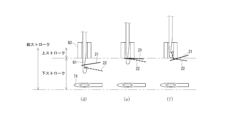
- FIGS. 7A to 7D are diagrams for explaining the operation of the binding device main body 50 in the Z-axis direction.
- the wire supplying section 70 (wire hanging section 71) is fixed to the binding device main body 50, and its position in the Z-axis direction does not change (see Figs. 4 and 5).
- the annular forming section 80 (operation section 81, pressing section 82) is configured to be movable in the Z-axis direction.
- the locking portion 812 of the operating portion 81 is disengaged from the insertion hole 74 of the wire hook portion 71 and is located in the +Z axis direction (upward) with respect to the insertion hole 74.
- the locking portion 812 of the operating portion 81 is also disengaged from the insertion portion 821 of the pressing portion 82 and is located below the insertion portion 821.
- the operating part 81 is lowered in the -Z-axis direction with respect to FIG. 7(a), and the locking part 812 of the operating part 81 is inserted into the insertion hole 74 of the wire hook part 71.
- the position of the pressing part 82 in the Z-axis direction has not changed with respect to FIG. 7(a).
- the operating part 81 is raised in the +Z-axis direction compared to FIG. 7(a)(b), and the locking part 812 of the operating part 81 is inserted into the insertion part 821 of the holding part 82.
- the position of the holding part 82 in the Z-axis direction has not changed compared to FIG. 7(a)(b).
- both the operating part 81 and the holding part 82 rise in the +Z-axis direction compared to FIG. 7(c).
- the locking part 812 of the operating part 81 rises together with the holding part 82 while remaining inserted into the insertion part 821 of the holding part 82.
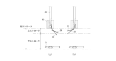
- [Movement of the binding device body in the X-axis and Y-axis directions] 8 is a diagram for explaining the operation of the binding device main body 50 in the X-axis direction and the Y-axis direction.
- the wire supplying section 70 (wire hooking section 71) and the annular forming section 80 (operation section 81, pressing section 82) constituting the binding device main body 50 move in the X-axis direction and the Y-axis direction with respect to the object W set in the wire harness binding processing device 200 while maintaining their relative positions in the X-axis direction and the Y-axis direction.
- the movement of the binding device main body 50 in the X-axis direction and the Y-axis direction is performed by the position control of the guide device 60 as described above.
- the binding device main body 50 moves, for example, in the order of positions P1, P2, ... P7, P8. Specifically, the binding device main body 50 moves in the X-axis direction so that the wire supply section 70 and the annular forming section 80 are alternately positioned on the +X side and -X side of the bound body W, while simultaneously moving a predetermined distance in the +Y-axis direction.
- the wire supply unit 70 and the annular forming unit 80 move to the +X side and -X side relative to the object to be bound W
- the wire supply unit 70 passes on the -Z side (below the object to be bound W) relative to the object to be bound W.
- the annular forming unit 80 passes on the +Z side (above the object to be bound W) relative to the object to be bound W.
- the binding device main body 50 moves a fixed distance in the +Y direction each time it reciprocates in the X direction, but the distance it moves in the +Y direction may be varied as necessary.
- the wire harness bundling processing device 200 repeatedly forms the first annular portion 21 and the second annular portion 22, and performs a bundling process in which a plurality of annular portions 20 (first annular portion 21, second annular portion 22) are connected to each other by repeatedly and continuously performing a connecting process (first connecting process and second connecting process) in which adjacent first annular portions and second annular portions are connected.
- the first connection step is performed when the binding device main body 50 (wire supply unit 70 and annular forming unit 80) is located on the +X side of the object to be bound W and when it moves from the +X side to the -X side.
- the second connection step is performed when the binding device main body 50 (wire supply unit 70 and annular forming unit 80) is located on the -X side of the object to be bound W and when it moves from the -X side to the +X side.
- the first connection step is performed when the binding device main body 50 (wire supply unit 70 and annular forming unit 80) is located, for example, at P1 and on path M1 moving from P1 to P2. Similarly, the first connection step is performed between P3 and path M3, between P5 and path M5, and between P7 and path M7.
- the first connection step is a step of connecting the second annular portion 22 to the first annular portion 21.
- the first annular portion 21 is formed by bending a portion of the wire material S, and another portion of the wire material S is inserted through the first annular portion 21, thereby forming the second annular portion 22 connected to the first annular portion 21.
- the second connection process is also performed when the binding device main body 50 (wire supply unit 70 and annular forming unit 80) is located at P2 and when it is located on path M2 moving from P2 to P3. Similarly, the second connection process is performed between P4 and path M4, between P6 and path M6, and between P8 and path M8.
- the second connection step is a step of connecting the first annular portion 21 to the second annular portion 22. Specifically, this step is a step of forming the first annular portion 21 connected to the second annular portion 22 by inserting and pulling out a portion of the wire material S through the second annular portion 22 formed on a portion of the wire material S.
- Figures 9A(a) to 9D(j) are diagrams for explaining the first connecting step.
- Figures 9A(a) to 9D(j) each show a schematic diagram of the wire hooking unit 71 of the wire supply unit 70, the operating unit 81 and the pressing unit 82 of the annular forming unit 80, and the first annular portion 21 and the second annular portion 22 formed by the wire S, as viewed from the +Y-axis direction.
- the first connection process shown in Figures 9A(a) to 9D(j) will be described as being performed when the binding device main body 50 (wire supply section 70 and annular forming section 80) is located at P1 in Figure 8 and when it is located on path M1 moving from P1 to P2.
- first and second connecting steps are in a swapped relationship between the first annular portion 21 and the second annular portion 22. Therefore, in the second connecting step, the first and second annular portions 21 and 22 in Figures 9A(a) to 9D(j) are in a swapped relationship.
- FIG. 9A(a) shows a state in which the operating unit 81 is lowered in the -Z axis direction at position P1 in FIG. 8, and the locking portion 812 of the operating unit 81 is inserted into the insertion hole 74 of the wire hook 71.
- the wire S is curved by being wound around the shaft 811 of the operating unit 81.
- the curved portion of the wire S wound around the shaft 811 forms the first annular portion 21.
- the portion of the wire S that is curved by being wound around the shaft 811 in FIG. 9A(a) is the portion that was curved by being locked to the locking portion 812 of the operating unit 81 in a previous process (not shown).
- the shaft 811 of the operating unit 81 is inserted into the curved portion of the wire S (a state in which the wire S is wound around).
- the wire hook 71 rotates, causing the wire S to be wound around the operating part 81 (see FIG. 6B).
- the curved portion of the wire hook 71 that is wound around the operating part 81 forms the second annular part 22.
- FIG. 9A(c) shows the state in which the operating part 81 is rotated about 90 degrees around the Z axis with respect to FIG. 9A(b) while being pulled up in the +Z direction from the insertion hole 74.
- the part that forms the second annular part 22 is in a state of being locked to the locking part 812 of the operating part 81.
- the part that forms the first annular part 21, which is hung around the shaft part 811 of the operating part 81, is also pulled up together with the operating part 81 due to friction.
- FIG. 9B(d) shows the state in which the operating part 81 has been further pulled up in the +Z-axis direction and rotated about 180 degrees around the Z-axis with respect to FIG. 9A(b).
- the part that forms the second annular part 22 is engaged with the locking part 812 of the operating part 81.
- the part that forms the first annular part 21, which is hung around the shaft part 811 of the operating part 81, is also pulled up together with the operating part 81.
- both the operating part 81 and the holding part 82 are raised in the +Z-axis direction.
- the locking part 812 of the operating part 81 is raised together with the holding part 82 while remaining inserted into the insertion part 821 of the holding part 82 (see Figure 7 (d)).
- This action causes the second annular part 22 to be pulled out largely relative to the first annular part 21.
- the wire supply part 70 and the annular forming part 80 move from P1 to P2 in Figure 8 relative to the object to be bound W, the operating part 81 and the holding part 82 are prevented from interfering with the object to be bound W.
- Figure 9C (h) shows the state in which both the operating part 81 and the holding part 82 have moved from P1 to P2 in Figure 8.
- the locking part 812 of the operating part 81 rises together with the holding part 82 while remaining inserted into the insertion part 821 of the holding part 82 (see Figure 7 (d)).
- This action causes the second annular part 22 to be pulled out largely relative to the first annular part 21.
- the operating part 81 and the holding part 82 rise in the +Z axis direction so as not to interfere with the object to be bound W.
- both the operating part 81 and the pressing part 82 are lowered in the -Z axis direction at position P2 in FIG. 8.
- the operating part 81 is lowered in the -Z axis direction relative to the pressing part 82. As the operating part 81 is lowered, the second annular part 22 that was engaged with the engaging part 812 moves and is now wrapped around the shaft part 811.
- the connecting process switches from the first connecting process to the second connecting process at position P2 in FIG. 8.
- the first connecting process as shown in FIG. 9A(a) to FIG. 9D(j) and the second connecting process in which the first annular portion 21 and the second annular portion 22 are swapped in FIG. 9A(a) to FIG. 9D(j) are repeatedly and continuously performed while moving in the X-axis direction and the Y-axis direction relative to the bound body W as shown in FIG. 8, thereby performing a binding process that mutually connects multiple annular portions 20 (first annular portion 21, second annular portion 22).
- [Wire harness bundling method] 10 is a flowchart showing a bundling process in the wire harness bundling method according to the present embodiment.
- the first annular portion 21 and the second annular portion 22 are repeatedly formed, and a connecting step of connecting adjacent first annular portions and second annular portions is repeatedly and continuously performed.
- the connecting process includes a first connecting process and a second connecting process.
- the first connecting process is a process of forming a second annular portion 22 connected to the first annular portion 21 by pulling out a part of the wire S so as to insert another part of the wire S into the first annular portion 21 formed by bending a part of the wire S.
- the second connecting process is a process of forming the first annular portion 21 connected to the second annular portion 22 by pulling out a part of the wire S so as to insert the second annular portion 22 into the second annular portion 22 formed on a part of the wire S.
- the first connecting step (SA1) and the second connecting step (SA2) are performed consecutively.
- the bundling process ends.
- the bundling process does not reach the set length (No in SA3), the bundling process continues (SA1).
- the binding body 10 has a plurality of annular portions 20 (first annular portion 21, second annular portion 22) formed in succession, and the plurality of annular portions 20 are arranged along the longitudinal direction of the bound body W, and adjacent annular portions 20 are connected to each other to bind the bound body W.
- the objects to be bound W are bound continuously by the binding body 10, which is made of flexible wire S, so the task of binding electrical wires with the binding body 10 can be automated and accelerated.
- the binding body 10 is less likely to shift position relative to the object to be bound W, and a decrease in the binding force for binding the electric wires can be suppressed.
- adjacent first annular portions 21 and second annular portions 22 are connected to each other, thereby connecting multiple annular portions 20 to each other.
- the first annular portion 21 and the second annular portion 22 are repeatedly formed and then connected, which speeds up the process of bundling the electric wires with the bundling body 10.
- the present invention is applicable to a wire harness bundling processing device that forms a wire harness in which bundled objects including multiple electric wires are bundled by a bundling object.
Landscapes
- Engineering & Computer Science (AREA)
- Manufacturing & Machinery (AREA)
- Mechanical Engineering (AREA)
- Basic Packing Technique (AREA)
- Insulated Conductors (AREA)
- Details Of Indoor Wiring (AREA)
- Installation Of Indoor Wiring (AREA)
- Supports For Pipes And Cables (AREA)
- Clamps And Clips (AREA)
Priority Applications (3)
| Application Number | Priority Date | Filing Date | Title |
|---|---|---|---|
| JP2024549347A JP7774917B2 (ja) | 2022-09-27 | 2023-09-25 | ワイヤハーネス結束処理装置 |
| EP23872222.7A EP4597526A1 (en) | 2022-09-27 | 2023-09-25 | Wire harness bundling device |
| US18/855,227 US20260094740A1 (en) | 2022-09-27 | 2023-09-25 | Wire harness bundling device |
Applications Claiming Priority (2)
| Application Number | Priority Date | Filing Date | Title |
|---|---|---|---|
| JP2022153739 | 2022-09-27 | ||
| JP2022-153739 | 2022-09-27 |
Publications (1)
| Publication Number | Publication Date |
|---|---|
| WO2024070997A1 true WO2024070997A1 (ja) | 2024-04-04 |
Family
ID=90477788
Family Applications (2)
| Application Number | Title | Priority Date | Filing Date |
|---|---|---|---|
| PCT/JP2023/034629 Ceased WO2024070997A1 (ja) | 2022-09-27 | 2023-09-25 | ワイヤハーネス結束処理装置 |
| PCT/JP2023/034659 Ceased WO2024071015A1 (ja) | 2022-09-27 | 2023-09-25 | ワイヤハーネスおよびワイヤハーネス結束処理方法 |
Family Applications After (1)
| Application Number | Title | Priority Date | Filing Date |
|---|---|---|---|
| PCT/JP2023/034659 Ceased WO2024071015A1 (ja) | 2022-09-27 | 2023-09-25 | ワイヤハーネスおよびワイヤハーネス結束処理方法 |
Country Status (6)
| Country | Link |
|---|---|
| US (1) | US20260094740A1 (https=) |
| EP (2) | EP4597526A1 (https=) |
| JP (2) | JP7774917B2 (https=) |
| CN (1) | CN119948579A (https=) |
| MX (1) | MX2025003447A (https=) |
| WO (2) | WO2024070997A1 (https=) |
Citations (4)
| Publication number | Priority date | Publication date | Assignee | Title |
|---|---|---|---|---|
| JPH02114317U (https=) * | 1989-02-28 | 1990-09-13 | ||
| JPH065031A (ja) | 1992-06-18 | 1994-01-14 | Canon Inc | 光ディスクドライブ装置 |
| US6233796B1 (en) * | 1996-09-14 | 2001-05-22 | Federal-Mogul Systems Protection Group S.A.S. | Wiring harness bundling |
| JP2008192456A (ja) | 2007-02-05 | 2008-08-21 | Yazaki Corp | ワイヤハーネスの製造装置及び製造方法 |
Family Cites Families (3)
| Publication number | Priority date | Publication date | Assignee | Title |
|---|---|---|---|---|
| SU388066A1 (ru) * | 1970-05-18 | 1976-07-25 | Устройство дл обв зки гибкой нитью жгутов | |
| DE2533640A1 (de) * | 1975-07-28 | 1977-02-03 | Boris Sergeevitsch Egorov | Verfahren zum binden einer gruppe paralleler elektrischer leitungen, einrichtung zur durchfuehrung dieses verfahrens und nach diesem verfahren gebundene elektrische sammelleitung |
| JPH065031U (ja) | 1992-06-22 | 1994-01-21 | 有限会社機電工業 | 制御用ケーブル |
-
2023
- 2023-09-25 JP JP2024549347A patent/JP7774917B2/ja active Active
- 2023-09-25 WO PCT/JP2023/034629 patent/WO2024070997A1/ja not_active Ceased
- 2023-09-25 EP EP23872222.7A patent/EP4597526A1/en active Pending
- 2023-09-25 CN CN202380066525.2A patent/CN119948579A/zh active Pending
- 2023-09-25 JP JP2024549358A patent/JP7812102B2/ja active Active
- 2023-09-25 WO PCT/JP2023/034659 patent/WO2024071015A1/ja not_active Ceased
- 2023-09-25 EP EP23872238.3A patent/EP4576124A4/en active Pending
- 2023-09-25 US US18/855,227 patent/US20260094740A1/en active Pending
-
2025
- 2025-03-24 MX MX2025003447A patent/MX2025003447A/es unknown
Patent Citations (4)
| Publication number | Priority date | Publication date | Assignee | Title |
|---|---|---|---|---|
| JPH02114317U (https=) * | 1989-02-28 | 1990-09-13 | ||
| JPH065031A (ja) | 1992-06-18 | 1994-01-14 | Canon Inc | 光ディスクドライブ装置 |
| US6233796B1 (en) * | 1996-09-14 | 2001-05-22 | Federal-Mogul Systems Protection Group S.A.S. | Wiring harness bundling |
| JP2008192456A (ja) | 2007-02-05 | 2008-08-21 | Yazaki Corp | ワイヤハーネスの製造装置及び製造方法 |
Also Published As
| Publication number | Publication date |
|---|---|
| CN119948579A (zh) | 2025-05-06 |
| MX2025003447A (es) | 2025-05-02 |
| EP4576124A1 (en) | 2025-06-25 |
| JP7774917B2 (ja) | 2025-11-25 |
| US20260094740A1 (en) | 2026-04-02 |
| EP4597526A1 (en) | 2025-08-06 |
| EP4576124A4 (en) | 2025-12-10 |
| JPWO2024070997A1 (https=) | 2024-04-04 |
| WO2024071015A1 (ja) | 2024-04-04 |
| JPWO2024071015A1 (https=) | 2024-04-04 |
| JP7812102B2 (ja) | 2026-02-09 |
Similar Documents
| Publication | Publication Date | Title |
|---|---|---|
| CN103459292B (zh) | 用于电梯系统的涂覆的绳或带 | |
| EP0441604A1 (en) | Braiding machine | |
| US20130181084A1 (en) | Wire bundling device and wire bundling method | |
| JP7774917B2 (ja) | ワイヤハーネス結束処理装置 | |
| CN111232280B (zh) | 一种绞纱自动分股、绑线、打结装置 | |
| CN104428229B (zh) | 细长元件从一个卷轴向另一卷轴的传递 | |
| CN1871116A (zh) | 长丝卷绕工艺中维持长丝位置的方法和装置 | |
| US12173450B2 (en) | Braiding, winding or spiralling machine and method for operating same | |
| EP0199461A2 (en) | Manufacture of elongate members such as strand and rope | |
| EP0872852A2 (en) | Universal cable take-off system | |
| JP3550372B2 (ja) | 巻線製造システムおよび巻線製造方法 | |
| EP1655740A1 (en) | Stranded wire, coil using this wire, noise filter device having this coil, and production method for stranded wire | |
| CN1117468A (zh) | 绕线机的线张力自动调节方法 | |
| KR101763101B1 (ko) | 와이어 권선결속 자동화 시스템 | |
| JP2879667B2 (ja) | ケーブル先導案内装置 | |
| JP3328592B2 (ja) | 巻線製造装置、巻線製造システムおよび巻線製造方法 | |
| KR101907796B1 (ko) | 소프트 액츄에이터 제조장치 및 이를 이용한 소프트 액츄에이터 제조방법 | |
| TW202600260A (zh) | 捆束裝置以及捆束系統 | |
| TW202600417A (zh) | 捆束裝置以及捆束系統 | |
| JP4666555B2 (ja) | 鋼線の複数本束巻き取り方法 | |
| CN117926486A (zh) | 一种复合纤维织带制备工艺及其制备装置 | |
| JP7624048B1 (ja) | 延線金車取付器具及び延線金車取付方法 | |
| JPH10243514A (ja) | ケーブル先導案内装置 | |
| TW202606936A (zh) | 捆束裝置以及捆束系統 | |
| CN121139645A (zh) | 一种基于单根纤维丝环绕合股成柔性软链条制备工艺 |
Legal Events
| Date | Code | Title | Description |
|---|---|---|---|
| 121 | Ep: the epo has been informed by wipo that ep was designated in this application |
Ref document number: 23872222 Country of ref document: EP Kind code of ref document: A1 |
|
| ENP | Entry into the national phase |
Ref document number: 2024549347 Country of ref document: JP Kind code of ref document: A |
|
| WWE | Wipo information: entry into national phase |
Ref document number: 2023872222 Country of ref document: EP |
|
| NENP | Non-entry into the national phase |
Ref country code: DE |
|
| ENP | Entry into the national phase |
Ref document number: 2023872222 Country of ref document: EP Effective date: 20250428 |
|
| WWP | Wipo information: published in national office |
Ref document number: 2023872222 Country of ref document: EP |